Eye Examination with the Slit Lamp. - Carl Zeiss, Inc.
Eye Examination with the Slit Lamp. - Carl Zeiss, Inc.
Eye Examination with the Slit Lamp. - Carl Zeiss, Inc.

You also want an ePaper? Increase the reach of your titles
YUMPU automatically turns print PDFs into web optimized ePapers that Google loves.
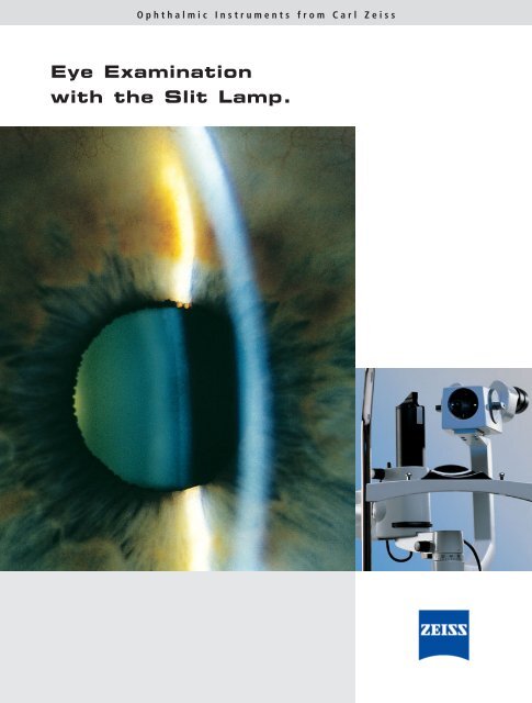
Ophthalmic Instruments from <strong>Carl</strong> <strong>Zeiss</strong><br />
<strong>Eye</strong> <strong>Examination</strong><br />
<strong>with</strong> <strong>the</strong> <strong>Slit</strong> <strong>Lamp</strong>.
In memory<br />
of Prof. Allvar Gullstrand<br />
Nobel Prize Winner in Physiology and Medicine<br />
05.06.1862 – 28.07.1930
<strong>Eye</strong> <strong>Examination</strong><br />
<strong>with</strong> <strong>the</strong> <strong>Slit</strong> <strong>Lamp</strong>.<br />
Contents<br />
1. Overview of applications .................................................................................................................... 2<br />
2. Design principles .................................................................................................................................. 3<br />
2.1 <strong>Slit</strong> illumination system .......................................................................................................................... 3<br />
2.2 <strong>Slit</strong> lamp microscope .............................................................................................................................. 5<br />
2.3 Mechanical system .................................................................................................................................. 8<br />
2.4 Electrical system...................................................................................................................................... 9<br />
2.5 Range of <strong>Carl</strong> <strong>Zeiss</strong> slit lamps ................................................................................................................ 9<br />
3. <strong>Examination</strong> methods – types of illumination....................................................................................14<br />
3.1 Observation by optical section ................................................................................................................14<br />
3.2 Direct diffuse illumination ......................................................................................................................16<br />
3.3 Indirect illumination ................................................................................................................................17<br />
3.4 Retro-illumination ..................................................................................................................................17<br />
3.5 Scattering sclero-corneal illumination ....................................................................................................19<br />
3.6 Fundus observation and gonioscopy <strong>with</strong> <strong>the</strong> slit lamp ............................................................................19<br />
3.7 Fluorescence observation and slit lamp microscopy in contact lens fitting ................................................24<br />
3.8 Assessment of lachrymal film ..................................................................................................................26<br />
3.9 O<strong>the</strong>r examination methods ....................................................................................................................27<br />
4. Documentation of findings ..................................................................................................................28<br />
4.1 Video documentation ..............................................................................................................................28<br />
4.2 Digital image recording and editing ........................................................................................................29<br />
5. Accessories............................................................................................................................................30<br />
5.1 Measurement of intraocular pressure ......................................................................................................30<br />
5.2 Length and angle measurement ..............................................................................................................32<br />
5.3 Miscellaneous ........................................................................................................................................32<br />
6. History of <strong>the</strong> slit lamp<br />
and development of <strong>the</strong> photography of <strong>the</strong> optical section ....................................................................33<br />
7. Bibliography<br />
1
2<br />
1. Overview of applications.<br />
Fig. 1<br />
Application of<br />
SL 120 <strong>Slit</strong> <strong>Lamp</strong><br />
Today <strong>the</strong> slit lamp is <strong>the</strong> ophthalmologist's most<br />
frequently used and most universally applicable<br />
examination instrument. The most important field of<br />
application is <strong>the</strong> examination of <strong>the</strong> anterior segment<br />
of <strong>the</strong> eye including <strong>the</strong> crystalline lens and <strong>the</strong><br />
anterior vitreous body.<br />
Supplementary optics such as contact lenses and<br />
additional lenses permit observation of <strong>the</strong> posterior<br />
segments and <strong>the</strong> iridocorneal angle that are not<br />
visible in <strong>the</strong> direct optical path.<br />
A number of accessories have been developed for<br />
slit lamps extending <strong>the</strong>ir range of application from<br />
pure observation to measurement, such as for<br />
measuring <strong>the</strong> intraocular pressure.<br />
The documentation of findings on electronic media<br />
is increasingly gaining importance as it provides a<br />
convenient medium for keeping track of a disease’s<br />
progress. It also facilitates <strong>the</strong> communication between<br />
physician and patient or between physicians.<br />
The use of <strong>the</strong> slit lamp in contact lens fitting is an<br />
important recent application worth mentioning. The<br />
modern instrument has increasingly gained applications<br />
beyond <strong>the</strong> traditional ophthalmologist´s<br />
practice.
2. Design principles.<br />
2.1 <strong>Slit</strong> illumination system<br />
The illumination system is intended to produce a slit<br />
image that is as bright as possible, at a defined distance<br />
from <strong>the</strong> instrument <strong>with</strong> its length, width, and<br />
position being variable. Today this is achieved using<br />
optical imaging <strong>with</strong> <strong>the</strong> so-called Köhler illumination<br />
(Fig. 2). The light source L is imaged in <strong>the</strong> objective O<br />
by <strong>the</strong> collector system K. The objective in turn<br />
produces an image at S in <strong>the</strong> mechanical slit located<br />
next to <strong>the</strong> collector system. The image of <strong>the</strong> light<br />
source at O is <strong>the</strong> exit pupil of <strong>the</strong> system. Köhler<br />
illumination provides a very homogeneous slit image<br />
even <strong>with</strong> a structured light source. This is an<br />
advantage over illumination systems imaging <strong>the</strong> light<br />
source in <strong>the</strong> slit and projecting <strong>the</strong> latter into <strong>the</strong> eye<br />
toge<strong>the</strong>r <strong>with</strong> <strong>the</strong> image of <strong>the</strong> light source. This<br />
method was used in 1911 in <strong>the</strong> first Gullstrand slit<br />
lamp and is <strong>the</strong>refore only of historical importance.<br />
The brightness of <strong>the</strong> slit image is characterised by<br />
<strong>the</strong> illuminance of <strong>the</strong> slit image which depends on <strong>the</strong><br />
luminance of <strong>the</strong> light source, <strong>the</strong> transmission of<br />
imaging optics, <strong>the</strong> size of <strong>the</strong> exit pupil, and <strong>the</strong><br />
distance between exit pupil and slit.<br />
The standard slit lamp is comprised of three elements:<br />
1.<strong>Slit</strong> illumination system<br />
Giving <strong>the</strong> instrument its name<br />
2.Stereomicroscope<br />
Similar to that used on o<strong>the</strong>r ophthalmic<br />
instruments, e.g. surgical microscopes<br />
3.Mechanical system<br />
Connecting <strong>the</strong> microscope to <strong>the</strong> illumination<br />
system and allowing for positioning of <strong>the</strong><br />
instrument<br />
Fig. 2<br />
Principle of Köhler illumination<br />
3
4<br />
Fig. 3<br />
Optical path<br />
in <strong>the</strong> stereomicroscope<br />
of a slit lamp<br />
2.<br />
The optical transmission is increased by antireflection<br />
coatings on all glass surfaces. The light loss<br />
caused by reflections is subsequently reduced to 1.5%<br />
or even down to 0.5% in <strong>the</strong> case of high-grade<br />
antireflection coatings. The total gain in brightness of<br />
<strong>the</strong> slit illumination compared to an uncoated system<br />
is about 20%, thus demonstrating <strong>the</strong> advantages<br />
offered by modern specially coated optics.<br />
The light source used on a slit lamp is ei<strong>the</strong>r a lowvoltage<br />
incandescent lamp or a halogen lamp. The<br />
latter being preferred because of its high luminance<br />
and colour temperature.<br />
According to physical laws <strong>the</strong> light scattering<br />
ability and fluorescence of transparent media is<br />
enhanced by such high luminance and colour<br />
temperature, allowing diagnostically important<br />
changes in colour to yellow to be much more easily<br />
recognised. Modern slit lamps (see Figs. 7 - 10)<br />
<strong>the</strong>refore employ halogen light sources.<br />
Design principles<br />
For certain examinations it is not so much an<br />
intense slit illumination that is required but a largefield<br />
diffuse illumination. For this reason some<br />
instruments provide an insertable ground glass screen<br />
at <strong>the</strong> plane of <strong>the</strong> exit pupil and of <strong>the</strong> filament<br />
image. The optical path is thus interrupted <strong>with</strong> <strong>the</strong><br />
ground glass screen acting as a secondary source.<br />
O<strong>the</strong>r examination methods require <strong>the</strong> spectral<br />
composition of <strong>the</strong> light to be changed (e.g. for fluorescence<br />
observation in contact lens fitting). For this<br />
purpose various filters are provided in <strong>the</strong> illumination<br />
system which can be easily swung into <strong>the</strong> beam path.<br />
The range of filters include exciter filters for<br />
fluorescence, green filters for contrast enhancement,<br />
and sometimes grey filters for reducing <strong>the</strong> illumination<br />
intensity while maintaining colour temperature.
Design principles<br />
2.2 <strong>Slit</strong> lamp microscope<br />
The user expects <strong>the</strong> slit lamp microscope to provide<br />
optimum stereoscopic observation <strong>with</strong> selectable<br />
magnification. The size of <strong>the</strong> field of view and <strong>the</strong><br />
depth of field are expected to be as large as possible,<br />
and <strong>the</strong>re should be enough space in front of <strong>the</strong><br />
microscope for manipulation on <strong>the</strong> eye.<br />
Fig. 3 shows <strong>the</strong> optical path of a stereomicroscope<br />
designed on <strong>the</strong> principle of <strong>the</strong> telescopic lens.<br />
With telescopic lens systems, larger working<br />
distances can be achieved when compared to simple<br />
magnifying systems. These systems consist of a<br />
telescope and an object-side magnifying lens. The<br />
object is located in <strong>the</strong> object-side focal point of <strong>the</strong><br />
magnifying lens that magnifies <strong>the</strong> object image<br />
projecting it virtually to infinity. This image is <strong>the</strong>n<br />
viewed <strong>with</strong> <strong>the</strong> respective magnification through <strong>the</strong><br />
telescope.<br />
Explanation of Fig. 3:<br />
Between objective O (focal length f1 ) and tube<br />
lenses T (f2 ) <strong>the</strong>re is a separate, parallel optical path<br />
for each eye. Hence, <strong>the</strong> object is located in <strong>the</strong> focal<br />
plane of O. Between O and T a telescopic system W<br />
each may be fitted (magnification factor g) to vary <strong>the</strong><br />
total magnification.<br />
Stereoscopic vision requires a defined convergence<br />
angle between <strong>the</strong> two visual axes. This convergence<br />
angle is obtained by a prismatic power in <strong>the</strong> objective<br />
transmitted off axis by both beams. The intermediate<br />
images produced by tube lenses T through rotatable<br />
prisms are viewed <strong>with</strong> eyepieces K (f3 ).<br />
The total angular magnification G of <strong>the</strong> system<br />
is calculated by <strong>the</strong> following formula:<br />
G<br />
f2 = _____ x g<br />
250 mm<br />
x __________<br />
f1 f3 (mm)<br />
2.<br />
Fig. 4<br />
Optical diagram<br />
of telescopic system<br />
5
6<br />
Fig. 5<br />
Galilean system<br />
2.<br />
The stereomicroscopes of our slit lamps use <strong>the</strong><br />
following instrument principle:<br />
Telescopic system<br />
Galilean system <strong>with</strong> telecentric optical path (Fig. 4)<br />
On this system, both optical paths have a common<br />
or main objective. This objective projects <strong>the</strong> object<br />
image to infinity which is viewed by a stereo tube that<br />
is basically a pair of telescopes. In practice <strong>the</strong> slit<br />
lamp requires magnifications of between 5x and 50x,<br />
<strong>the</strong> most commonly used being 10x, 16x, and 25x. The<br />
microscope magnification can be varied by changing<br />
<strong>the</strong> eyepieces, but a simpler and more elegant solution<br />
is however, a magnification changer using variable<br />
optical elements. When <strong>the</strong> magnification is changed,<br />
<strong>the</strong> position of <strong>the</strong> object plane must of course not<br />
change. A tried and tested means of changing <strong>the</strong><br />
magnification is a Galilean telescope. Here, in a<br />
rotatable drum whose axis is perpendicular to <strong>the</strong><br />
optical axes, two small Galilean telescopes are<br />
arranged that are inclined to each o<strong>the</strong>r and can be<br />
looked through in ei<strong>the</strong>r direction. Thus, <strong>the</strong>y provide<br />
four different magnifications. A fifth magnification<br />
results from <strong>the</strong> free aperture available on <strong>the</strong> drum.<br />
Design principles<br />
The magnification changers of <strong>the</strong> SL 115 Classic,<br />
SL 120 and SL 130 <strong>Slit</strong> <strong>Lamp</strong>s are based on this<br />
principle.<br />
The binocular tube of <strong>the</strong> slit lamp holds <strong>the</strong><br />
eyepieces at <strong>the</strong> same time ensuring a defined<br />
distance between <strong>the</strong>m and <strong>the</strong> main objective<br />
(= mechanical tube length).<br />
In recent years, slit lamps that employ a stereomicroscope<br />
combined <strong>with</strong> a telescopic system have<br />
been successful. These stereomicroscopes have a<br />
straight binocular tube (parallel tube) that enables<br />
fatigue-free viewing through <strong>the</strong> slit lamp when used<br />
over longer periods.<br />
For examinations where <strong>the</strong> ophthalmologist<br />
observes <strong>the</strong> patient's eye alternately through <strong>the</strong> slit<br />
lamp and <strong>with</strong> <strong>the</strong> unaided eye (accommodated!), a<br />
convergent light path is recommended (convergent<br />
tube). It is known that <strong>the</strong>re is a relationship between<br />
<strong>the</strong> focal distance of <strong>the</strong> observers adjusted eye to <strong>the</strong><br />
viewed object, i.e. <strong>the</strong> accommodation, and <strong>the</strong><br />
convergence of <strong>the</strong>ir eyes to that object.<br />
The standard SL 120 and SL 130 <strong>Slit</strong> <strong>Lamp</strong>s are<br />
supplied <strong>with</strong> a convergent tube of f = 140 mm.<br />
Parallel tubes being available as accessories.<br />
Besides <strong>the</strong> magnification, <strong>the</strong> user is usually<br />
interested in <strong>the</strong> following optical criteria:<br />
- Resolution<br />
- Brightness<br />
- Depth of field<br />
- Stereo angle or stereo base<br />
- Back focal distance
Design principles<br />
The resolution of a microscope (<strong>the</strong> smallest<br />
distance between two points that can be separated) is<br />
determined by its numerical aperture. With a given<br />
aperture it is ineffectual to increase <strong>the</strong> microscope<br />
magnification beyond a certain point, <strong>the</strong> so-called<br />
useful magnification, over this <strong>the</strong> image will just be<br />
larger <strong>with</strong>out an increase in resolution. On <strong>the</strong> o<strong>the</strong>r<br />
hand it is not advisable to increase <strong>the</strong> aperture<br />
beyond <strong>the</strong> value specified by a given magnification<br />
ei<strong>the</strong>r, as in this case <strong>the</strong> resolution is limited by <strong>the</strong><br />
acuity and pupil size of <strong>the</strong> observer, also <strong>the</strong><br />
performance of <strong>the</strong> optics would not be fully utilised.<br />
The exit pupils of a good slit lamp microscope range<br />
from 0.8 to 2.7 mm depending on magnification.<br />
The depth of field of <strong>the</strong> microscope is of great<br />
importance in <strong>the</strong> use of <strong>the</strong> slit lamp. It has three<br />
components:<br />
- Depth of focus<br />
- Depth of accommodation<br />
- Depth of resolution<br />
Within <strong>the</strong> eye <strong>the</strong>re exists a smallest resolvable<br />
angle (or minimum angular separation) at which an<br />
image point and its circles of least confusion are seen<br />
equally sharp. This is <strong>the</strong> depth of focus. The depth<br />
of accommodation, however, results from <strong>the</strong> change<br />
in refractive power of <strong>the</strong> eyepiece/eye system,<br />
whereby <strong>the</strong> point of best visual acuity is shifted<br />
relative to <strong>the</strong> eyepiece plane. The depth of<br />
resolution is due to <strong>the</strong> diffraction of light at <strong>the</strong><br />
microscope aperture. As a result of diffraction, object<br />
differentiation <strong>with</strong>in <strong>the</strong> depth range is impossible,<br />
<strong>the</strong> depth of resolution is <strong>the</strong>refore similar to <strong>the</strong><br />
depth of field.<br />
As <strong>with</strong> illumination, <strong>the</strong> demand for maximum<br />
brightness conflicts <strong>with</strong> that of maximum depth<br />
of field. Thus, a "brighter" slit lamp may have <strong>the</strong><br />
serious drawback of a lower depth of field if its brightness<br />
is not based on lamp brightness alone. The<br />
aperture of a good slit lamp microscope is near to 0.05<br />
for medium magnifications. The aperture of <strong>the</strong> new<br />
slit lamps ranges from 0.05 to 0.08.<br />
Stereoscopic vision is <strong>the</strong> basis of slit lamp microscopy.<br />
The wish to make <strong>the</strong> convergence angle as<br />
large as possible is counteracted by <strong>the</strong> demand for<br />
observation through limited apertures such as <strong>the</strong><br />
pupil and contact lens mirrors (cf. 3.6 "Fundus<br />
observation and gonioscopy"). For this reason good<br />
slit lamp microscopes work <strong>with</strong> a convergence angle<br />
of between 10° and 15°. The SL 120 and SL 130<br />
<strong>Slit</strong> <strong>Lamp</strong>s have a convergence angle of 12.5°, <strong>the</strong><br />
SL 115 Classic <strong>Slit</strong> <strong>Lamp</strong> employs a convergence angle<br />
of 10°.<br />
The backfocal distance is ano<strong>the</strong>r parameter of<br />
<strong>the</strong> slit lamp microscope that is of special interest. The<br />
back focal distance is <strong>the</strong> distance of <strong>the</strong> subject from<br />
<strong>the</strong> front lens surface of <strong>the</strong> microscope. The back focal<br />
distance must have a certain minimum length to give<br />
<strong>the</strong> operator sufficient space for manipulation. If it is<br />
too long, manipulations on <strong>the</strong> eye are difficult,<br />
because of <strong>the</strong> resulting extended and uncomfortable<br />
position of <strong>the</strong> arms. Moreover, <strong>with</strong> a given objective<br />
aperture, <strong>the</strong> numerical aperture is reduced and thus<br />
<strong>the</strong> brightness. The back focal distance of a slit lamp<br />
should range between 90 mm and 120 mm. On <strong>the</strong><br />
SL 120 and SL 130 <strong>Slit</strong> <strong>Lamp</strong>s, it is approx. 106 mm; on<br />
<strong>the</strong> SL 115 Classic <strong>Slit</strong> <strong>Lamp</strong> it is approx. 118 mm.<br />
2.<br />
7
8<br />
Fig. 6<br />
Optical path of<br />
SL 120 <strong>Slit</strong> <strong>Lamp</strong><br />
2.<br />
2.3 Mechanical system<br />
The mechanical system of <strong>the</strong> modern slit lamp has<br />
developed over 80 years and combines <strong>the</strong> requirements<br />
of operating comfort and universal application.<br />
Fig. 6 shows <strong>the</strong> functional connections of <strong>the</strong><br />
illumination system to <strong>the</strong> stereomicroscope by means<br />
of <strong>the</strong> mechanical support. The illumination system<br />
and <strong>the</strong> microscope can both be swung about a<br />
common vertical axis independent of each o<strong>the</strong>r. The<br />
visual axis is a virtual extension of <strong>the</strong> mechanical<br />
instrument axis, <strong>the</strong> rotational point being located<br />
below <strong>the</strong> patient's eye. The slit is normally focused to<br />
Design principles<br />
<strong>the</strong> axial plane and can be seen sharply defined at <strong>the</strong><br />
microscope focal point. During an examination, this<br />
axis of rotation is moved to <strong>the</strong> position of <strong>the</strong> object<br />
to be observed. This is achieved <strong>with</strong> <strong>the</strong> aid of a<br />
mechanical instrument base containing a cross-slide<br />
system and carrying <strong>the</strong> mechanical support axis of <strong>the</strong><br />
illumination system and <strong>the</strong> microscope. The<br />
instrument base is moved horizontally <strong>with</strong> a single<br />
control element - <strong>the</strong> joystick control. Additionally <strong>the</strong><br />
instrument base contains a vertical control mechanism<br />
allowing <strong>the</strong> slit and <strong>the</strong> viewing axis to be adjusted<br />
vertically. This vertical control is typically integrated<br />
into <strong>the</strong> joystick and operated by rotating it. Thus, <strong>the</strong><br />
operator can adjust <strong>the</strong> instrument to <strong>the</strong> object in all<br />
three space coordinates (3D joystick control lever).<br />
Modern slit lamps not only permit <strong>the</strong> illumination<br />
system to be swung through in front of <strong>the</strong> microscope,<br />
<strong>the</strong>y also have a middle position <strong>with</strong> a click<br />
stop which locates <strong>the</strong> illuminating prism between <strong>the</strong><br />
two microscope beams. This prism being extremely<br />
narrow, allows stereoscopic observation through <strong>the</strong><br />
microscope around <strong>the</strong> prism.<br />
There are a number of o<strong>the</strong>r important functions<br />
provided by <strong>the</strong> mechanical system:<br />
a) The slit image which is normally in a vertical position<br />
can be rotated continuously through ± 90° to<br />
<strong>the</strong> horizontal position.<br />
b)In <strong>the</strong> horizontal position <strong>the</strong> direction of <strong>the</strong> slit<br />
illumination can be changed so that <strong>the</strong>re is a<br />
defined angle between <strong>the</strong> microscope axis and <strong>the</strong><br />
axis of <strong>the</strong> slit illumination. On some instruments,<br />
this is effected by a tilting prism (15° from below).<br />
O<strong>the</strong>r instruments, such as <strong>the</strong> SL 120, and SL 130<br />
slit lamps, have a vertically adjustable prism head<br />
(tiltable between 0 and 20°). This is useful for<br />
examinations <strong>with</strong> mirror contact lenses.<br />
c) For retro-illumination <strong>the</strong> prism head can be rotated<br />
from <strong>the</strong> central click stop to <strong>the</strong> right and left. This<br />
allows <strong>the</strong> slit image to travel laterally.
Design principles<br />
As mentioned above, almost all slit lamp types have<br />
a common mechanical axis of rotation. The various<br />
makes only differ in <strong>the</strong> arrangement of <strong>the</strong><br />
illuminating beam to ei<strong>the</strong>r below <strong>the</strong> microscope<br />
body or above it, or by <strong>the</strong> configuration of <strong>the</strong><br />
illumination beam being folded once or twice by<br />
prisms or mirrors.<br />
Two o<strong>the</strong>r special types of slit lamp:<br />
- The hand slit lamp is a handy portable unit providing<br />
for slit lamp examinations on sitting or<br />
recumbent patients in or out of <strong>the</strong> ophthalmologic<br />
practice (Fig. 10, page 11).<br />
- The bedside or surgical slit lamp is a combination of<br />
an operating microscope <strong>with</strong> a swivelling slit illumination<br />
system designed for <strong>the</strong> examination and<br />
treatment of recumbent patients. For this reason<br />
<strong>the</strong>re is no real axis of rotation of <strong>the</strong> illumination<br />
system but ra<strong>the</strong>r a curved mechanical guide <strong>with</strong> a<br />
virtual axis.<br />
2.4 Electrical system<br />
The only electrical unit a slit lamp requires normally<br />
is a low-voltage supply (mains power pack) for<br />
powering <strong>the</strong> low-voltage filament lamp or <strong>the</strong> more<br />
modern and brighter halogen lamp.<br />
It is also an advantage to have a rheostat which<br />
varies <strong>the</strong> lamp voltage <strong>with</strong>in a certain range to<br />
enable <strong>the</strong> brightness to be adjusted to <strong>the</strong> specific<br />
requirements.<br />
2.5 Range of <strong>Carl</strong> <strong>Zeiss</strong><br />
slit lamps<br />
The slit lamps from <strong>Carl</strong> <strong>Zeiss</strong> feature outstanding<br />
performance. The optical transmission of <strong>the</strong> observation<br />
system is extremely high. This results in a<br />
minimal light loss in observation and documentation,<br />
which in turn reduces light levels for <strong>the</strong> patient.<br />
Due to <strong>the</strong> high resolution, even <strong>the</strong> finest structures<br />
become visible <strong>with</strong> a high contrast. The stereo angle<br />
of 12.5° provides for <strong>the</strong> improved three-dimensional<br />
differentiation of details to assist in obtaining a<br />
reliable diagnosis.<br />
<strong>Eye</strong>pieces <strong>with</strong> an exit pupil lying far beyond <strong>the</strong><br />
optical surfaces (super high-eyepoint eyepieces) also<br />
allow spectacle wearers to operate <strong>the</strong> slit lamp<br />
<strong>with</strong>out restriction. Practice-oriented operating comfort<br />
is ensured by <strong>the</strong> single-hand joystick control for fast<br />
and precise positioning of <strong>the</strong> instrument in all three<br />
coordinates as well as conveniently positioned<br />
controls allowing for sensitive adjustment of <strong>the</strong> slit<br />
image. These <strong>Carl</strong> <strong>Zeiss</strong> slit lamps have been developed<br />
down to <strong>the</strong> last detail to provide an instrument<br />
designed to aid a sound diagnosis.<br />
2.<br />
9
10<br />
2.<br />
Fig. 7<br />
SL 115 Classic <strong>Slit</strong> <strong>Lamp</strong><br />
The SL 115 Classic <strong>Slit</strong> <strong>Lamp</strong><br />
is <strong>the</strong> practice-oriented routine instrument for<br />
examination and measurement of <strong>the</strong> eye. The<br />
integrated yellow filter and <strong>the</strong> slit length of 14 mm<br />
provide optimum conditions for contact lens fitting.<br />
The revolving objective changer allows overall<br />
magnifications of 8x, 12x and 20x. The handy plugand-play<br />
concept – <strong>the</strong> slit lamp is supplied completely<br />
mounted – minimizes set-up work. The SL 115 Classic<br />
<strong>Slit</strong> <strong>Lamp</strong> may, of course, be retrofitted <strong>with</strong> a compact<br />
Fig. 8<br />
SL 120 <strong>Slit</strong> <strong>Lamp</strong><br />
video camera.<br />
The SL 120 <strong>Slit</strong> <strong>Lamp</strong><br />
Design principles<br />
is <strong>the</strong> powerful universal instrument <strong>with</strong> 5-step<br />
magnification changer. In combination <strong>with</strong> 10x<br />
eyepieces, <strong>the</strong> magnification is adjustable from 5x to<br />
32x. As standard <strong>the</strong> instrument has a convergent tube<br />
of f = 140 mm, a parallel tube of f = 140 mm being<br />
available as an option. The slit width is continuously<br />
adjustable from 0 to 14 mm. The slit length may be<br />
varied continuously from 1 – 6 mm and in steps of 0.5,<br />
3.5, 8 and 14 mm.
Design principles<br />
Fig. 9<br />
SL 130 <strong>Slit</strong> <strong>Lamp</strong><br />
The SL 130 <strong>Slit</strong> <strong>Lamp</strong><br />
is a universal diagnostic instrument <strong>with</strong> versatile<br />
accessories for measurement and documentation.<br />
The slit lamp differs from <strong>the</strong> previously described<br />
models in <strong>the</strong> different position of slit controls. <strong>Slit</strong><br />
adjustment is possible from ei<strong>the</strong>r <strong>the</strong> right or left and<br />
permits viewing <strong>with</strong> <strong>the</strong> slit illuminator in <strong>the</strong> middle<br />
position. This enables efficient and sensitive operation<br />
particularly when using this slit lamp for laser treatment.<br />
The applications of this slit lamp extend from <strong>the</strong><br />
anterior segment through <strong>the</strong> vitreous body to <strong>the</strong><br />
fundus.<br />
Fig. 10<br />
HSO 10 Hand <strong>Slit</strong> <strong>Lamp</strong><br />
The HSO 10 Hand <strong>Slit</strong> <strong>Lamp</strong><br />
being a portable instrument completes <strong>the</strong> slit lamp<br />
range. It is <strong>the</strong> ideal combination of a binocular slit<br />
lamp <strong>with</strong> an indirect ophthalmoscope, for <strong>the</strong> examination<br />
of <strong>the</strong> anterior and posterior eye segment of<br />
sitting or recumbent patients. Its special feature is <strong>the</strong><br />
bilateral lockable arc guide providing true, convenient<br />
single hand operation of <strong>the</strong> instrument. A rechargeable<br />
battery fur<strong>the</strong>r increases <strong>the</strong> mobility of this slit<br />
lamp.<br />
2.<br />
11
12<br />
2.<br />
Instrument specifications<br />
<strong>Zeiss</strong> slit lamps in detail<br />
SL 115 Classic <strong>Slit</strong> <strong>Lamp</strong><br />
Design principles<br />
Magnifications 8x, 12x, 20x<br />
Field of view 25 mm – 10 mm<br />
<strong>Eye</strong>piece magnification 10x high-eyepoint eyepieces, ± 8D compensation of ametropia<br />
Width of slit image 0 – 14 mm, continuously adjustable<br />
Length of slit image 0.5, 3.5, 8, 14 mm, in steps<br />
1 – 14 mm, continuously adjustable<br />
Angle of slit image ± 90°, continuously adjustable<br />
Decentration of slit image Variable, <strong>with</strong> click stop at 0°<br />
Swivel range of slit prism 180°, scale for angular difference, click stop at 0°<br />
Angle of incidence 0°, horizontal<br />
Filters Blue, green (red-free) and swing-in diffusing screen;<br />
barrier filter (yellow), swing-in type; UV protection filter, heat-absorbing filter<br />
Free working distance<br />
exit prism to patient eye<br />
73 mm<br />
Travel of instrument base Vertical: 30 mm, X-axis: 110 mm, Y-axis: 90 mm<br />
Vertical travel of headrest 58 mm<br />
Light source 6V 10W halogen lamp<br />
<strong>Lamp</strong> brightness Continuously adjustable<br />
Power requirements 100V to 240V ±10%, self-sensing, 50-60 Hz<br />
Weight Basic unit: 9.75 kg; headrest: 1.25 kg<br />
SL 120 <strong>Slit</strong> <strong>Lamp</strong><br />
Magnifications 5x, 8x, 12x, 20x, 32x<br />
(6x, 10x, 16x, 25x, 40x <strong>with</strong> optional 12.5x eyepiece)<br />
Field of view 40 mm – 6 mm<br />
<strong>Eye</strong>piece magnification 10x super high-eyepoint eyepieces, ± 8D compensation of ametropia<br />
Width of slit image 0 – 14 mm, continuously adjustable<br />
Length of slit image 0.5, 3.5, 8, 14 mm, in steps<br />
1 – 6 mm, continuously adjustable<br />
Angle of slit image ± 90°, continuously adjustable, Tabo angle scale<br />
Decentration of slit image ± 4° horizontal, click stop at 0°<br />
Swivel range of slit prism 180°, scale for angular difference<br />
Angle of incidence 0° – 20°, <strong>with</strong> tiltable prism head (optional)<br />
Filters Blue, green (red-free) and swing-in diffusing screen;<br />
heat-absorbing filter<br />
Free working distance<br />
exit prism to patient eye<br />
60 mm<br />
Travel of instrument base Vertical: 30 mm, X-axis: 110 mm, Y-axis: 90 mm<br />
Vertical travel of headrest 60 mm<br />
Light source 6V 20W halogen lamp<br />
<strong>Lamp</strong> brightness Continuously adjustable<br />
Power requirements 100V to 240V ±10%, self-sensing, 50-60 Hz<br />
Weight Basic unit: 9.25 kg; headrest: 1.25 kg
Design principles<br />
SL 130 <strong>Slit</strong> <strong>Lamp</strong><br />
Magnifications 5x, 8x, 12x, 20x, 32x<br />
(6x, 10x, 16x, 25x, 40x <strong>with</strong> optional 12.5x eyepiece)<br />
Field of view 40 mm – 6 mm<br />
<strong>Eye</strong>piece magnification 10x super high-eyepoint eyepieces, ± 8D compensation of ametropia<br />
Width of slit image 0 – 14 mm, continuously adjustable<br />
Length of slit image 0.3, 2.5, 3.5, 7, 10, 14 mm, triple slit<br />
Angle of slit image ± 90°, continuously adjustable<br />
Decentration of slit image ± 4° horizontal, click stop at 0°<br />
Swivel range of slit prism 180°, scale for angular difference<br />
Angle of incidence 0° – 20°, tiltable<br />
Filters Blue, green (red-free), grey (neutral) and swing-in diffusing screen;<br />
heat-absorbing filter<br />
Free working distance<br />
exit prism to patient eye<br />
66 mm<br />
Travel of instrument base Vertical: 30 mm, X-axis: 110 mm, Y-axis: 90 mm<br />
Vertical travel of headrest 60 mm<br />
Light source 6V 20W halogen lamp<br />
<strong>Lamp</strong> brightness Continuously adjustable<br />
Power requirements 100V to 240V ±10%, self-sensing, 50-60 Hz<br />
Weight Basic unit: 9.85 kg; headrest: 1.25 kg<br />
HSO 10 Hand <strong>Slit</strong> <strong>Lamp</strong><br />
Microscope Straight binocular tube f = 80 mm<br />
<strong>with</strong> 50 – 75 mm pupillary distance scale<br />
High-eyepoint eyepiece<br />
(firmly mounted)<br />
f = 13 mm <strong>with</strong> +8 to –4D compensation of ametropia<br />
Objective f = 125 mm<br />
<strong>Slit</strong> width Steps of 0.15 and 0.75 mm<br />
<strong>Slit</strong> length 2 – 12 mm, continuously adjustable<br />
Angle of incidence 0 – 30° to right or left, <strong>with</strong> clamp<br />
Total weight 850 g (<strong>with</strong>out battery)<br />
Case Carrying case<br />
Power requirements<br />
for battery charger<br />
110V, 220V; 50 – 60 Hz<br />
2.<br />
13
14<br />
3. <strong>Examination</strong> methods –<br />
types of illumination.<br />
Fig. 11<br />
Direct focal illumination<br />
Biomicroscopy of <strong>the</strong> living eye is a routine ophthalmologic<br />
examination. The slit lamp enables <strong>the</strong> user to<br />
inspect individual eye segments in quick succession to<br />
obtain a general impression of <strong>the</strong> eye and make a<br />
diagnosis.<br />
In a slit lamp, <strong>the</strong> most important type of illumination<br />
is <strong>the</strong> optical section. All o<strong>the</strong>r techniques are<br />
variations.<br />
For survey examination of <strong>the</strong> anterior segment <strong>the</strong><br />
slit is adjusted to full aperture. This results in a circular,<br />
very bright and evenly illuminated field that is<br />
slightly smaller than <strong>the</strong> microscope's field of view. By<br />
placing a ground glass into <strong>the</strong> optical path <strong>the</strong> entire<br />
field of view is illuminated.<br />
It is well known that <strong>the</strong> structure of transparent<br />
objects such as <strong>the</strong> cornea, anterior chamber, eye lens,<br />
and vitreous body can only be seen poorly in<br />
transmitted or reflected light, as <strong>the</strong> relative amplitude<br />
modulation of light is too weak and <strong>the</strong> phase<br />
modulation is not perceived by <strong>the</strong> eye. However, such<br />
objects can generally be observed well in scattered or<br />
fluorescent light.<br />
The basic methods of examination can be classified<br />
by <strong>the</strong> following illumination techniques.<br />
3.1 Observation<br />
by optical section<br />
Observation <strong>with</strong> an optical section or direct focal<br />
illumination (Fig. 11) is <strong>the</strong> most frequently applied<br />
method of examination <strong>with</strong> <strong>the</strong> slit lamp. With this<br />
method, <strong>the</strong> axes of illuminating and viewing path<br />
intersect in <strong>the</strong> area of <strong>the</strong> anterior eye media to be<br />
examined, for example, <strong>the</strong> individual corneal layers.<br />
The angle between illuminating and viewing path<br />
should be as large as possible (up to 90°), whereas <strong>the</strong><br />
slit length should be kept small to minimise dazzling<br />
<strong>the</strong> patient. With a narrow slit (about 0.1 mm to 0.2 mm)<br />
and a sufficiently small angular aperture, <strong>the</strong> illu-
<strong>Examination</strong> methods – types of illumination<br />
minating beam takes <strong>the</strong> form of two knife blades<br />
placed edge to edge. Scattered light appears only in<br />
this "optical section". The intensity of scattered light<br />
depends on <strong>the</strong> object structures and increases <strong>with</strong><br />
increasing slit brightness and <strong>the</strong> higher proportion of<br />
short-wave light obtained by an increased colour temperature<br />
of <strong>the</strong> light source.<br />
For good quality observations <strong>with</strong> a slit lamp it is<br />
very important that <strong>the</strong> light source delivers sufficient<br />
short-wave light containing a high as possible blue<br />
element, <strong>the</strong> colour temperature of <strong>the</strong> lamp <strong>the</strong>refore<br />
should also be high, a requirement normally satisfied<br />
by modern halogen lamps.<br />
In conjunction <strong>with</strong> <strong>the</strong> stereomicroscope an optical<br />
section permits very precise depth information providing<br />
precise data of <strong>the</strong> shape of interfaces of<br />
transparent media. With a narrow slit and clear media,<br />
<strong>the</strong> images of slit and object appear sharply focused at<br />
<strong>the</strong> same time. <strong>Slit</strong> width and magnification may be<br />
varied depending on <strong>the</strong> object to be examined. With<br />
this method, brilliant optical section images can be<br />
obtained from <strong>the</strong> cornea through to <strong>the</strong> rear face of<br />
<strong>the</strong> crystalline lens.<br />
With a narrow slit, <strong>the</strong> depth and position of different<br />
objects (e.g. <strong>the</strong> penetration depth of foreign<br />
bodies, shape of <strong>the</strong> lens etc.) can be resolved more<br />
easily. With a wide slit <strong>the</strong>ir extension and shape are<br />
visible more clearly (e.g. depth extension of injuries). It<br />
is <strong>the</strong>refore useful to vary <strong>the</strong> slit width during <strong>the</strong><br />
examination.<br />
At <strong>the</strong> cornea an optical section gives a luminous<br />
prismatic tissue section. The corneal epi<strong>the</strong>lium is<br />
visible in a very thin precisely focused optical section<br />
as a thin blue streak right in front of <strong>the</strong> parenchyma.<br />
<strong>Examination</strong>s of <strong>the</strong> anterior chamber are performed<br />
<strong>with</strong> wider slit. At low magnification <strong>the</strong> Tyndall light<br />
(Tyndall phenomenon in aqueous humour) is visible in<br />
front of <strong>the</strong> dark pupil. Cells in <strong>the</strong> aqueous humour,<br />
however, are visible only at higher magnifications.<br />
During observation it is important that <strong>the</strong> background<br />
always remains as dark as possible.<br />
The crystalline lens is particularly suited for viewing<br />
via an optical section. where <strong>the</strong> discontinuity zones<br />
can be made visible <strong>with</strong> a narrow slit. For examination<br />
of <strong>the</strong> anterior segments of <strong>the</strong> vitreous body it is<br />
advisable to use <strong>the</strong> smallest possible slit length to<br />
avoid dazzling of both patient and examiner. In <strong>the</strong>se<br />
examinations, slit brightness should be high.<br />
The slit lamp is specially configured for observation<br />
<strong>with</strong> an optical section. As both microscope and illumination<br />
system are mechanically coupled, <strong>the</strong> slit<br />
image is always located in <strong>the</strong> focal plane and <strong>the</strong><br />
centre of <strong>the</strong> field of view of <strong>the</strong> microscope independent<br />
of focusing and selected magnification.<br />
Experience has shown that this relationship, if true in<br />
air, also applies <strong>with</strong> sufficient accuracy to <strong>the</strong><br />
refracting ocular media, provided <strong>the</strong> operator has<br />
adjusted <strong>the</strong> eyepieces correctly to match his own<br />
refraction.<br />
The optical section is rotatable about <strong>the</strong> slit axis.<br />
The slit itself can be aligned vertically or horizontally.<br />
Horizontal positioning of <strong>the</strong> slit however, is an exceptional<br />
case in optical section examinations, mainly<br />
because stereoscopic vision is restricted if <strong>the</strong> slit is<br />
aligned horizontally. The reason for this is that <strong>the</strong> slit<br />
is no longer perpendicular to <strong>the</strong> plane in which <strong>the</strong><br />
viewing axes of <strong>the</strong> microscope and <strong>the</strong> lateral disparities<br />
of <strong>the</strong> observer lie.<br />
3.<br />
15
16<br />
3.<br />
Fig 12<br />
Direct diffuse illumination<br />
Main applications<br />
- Illumination methods for features that stood out in<br />
diffuse illumination but could not be observed in<br />
detail; particularly suitable for <strong>the</strong> assessment of<br />
cataracts, scars, nerves, vessels, etc.<br />
- Observation by optical section is also of great<br />
importance for <strong>the</strong> determination of <strong>the</strong> stabilisation<br />
axis of toric contact lenses (in connection <strong>with</strong><br />
a micrometer eyepiece or an appropriately inclined<br />
slit).<br />
- Optical sections through <strong>the</strong> crystalline lens are also<br />
particularly good. Capsule, cortex, lens star and<br />
cataracts can be observed <strong>with</strong>out difficulty.<br />
Recommended settings<br />
Illumination<br />
- Narrow slit<br />
- Angle of slit illumination system 0° - 45°<br />
(for reflected light bright field illumination)<br />
- Angle of slit illumination system 45° - 90°<br />
(for reflected light dark field illumination)<br />
For direct focal illumination <strong>with</strong> wide slit<br />
<strong>Slit</strong> width: > 0.5 mm<br />
Magnification: approx. 20x - 32x,<br />
if necessary, higher<br />
Observation of details, e.g. stromal striae.<br />
<strong>Examination</strong> methods – types of illumination<br />
For direct focal illumination <strong>with</strong> narrow slit:<br />
<strong>Slit</strong> width: 0.1 - 0.3 mm<br />
Magnification: maximum<br />
This is <strong>the</strong> ideal illumination for minute details providing<br />
sufficient contrast and little glare. With this<br />
method however, <strong>the</strong> reduction of <strong>the</strong> depth of field<br />
caused by kerato-ectasia is all too noticeable. In <strong>the</strong><br />
centre of <strong>the</strong> image however this effect is not so<br />
marked. The narrow slit should also be used for corneal<br />
profile observations<br />
3.2 Direct diffuse illumination<br />
If media, especially that of <strong>the</strong> cornea, are opaque,<br />
optical section images are often impossible depending<br />
on severity. In <strong>the</strong>se cases, direct diffuse illumination<br />
(Fig. 12) may be used to advantage. For this, <strong>the</strong> slit is<br />
opened very wide and a diffuse, attenuated survey<br />
illumination is produced by inserting a ground glass<br />
screen or diffuser in <strong>the</strong> illuminating path.<br />
Main applications<br />
This illumination method is applied for:<br />
- general surveys of anterior eye segments<br />
- general observation of <strong>the</strong> surfaces<br />
of crystalline lens and cornea<br />
- assessment of <strong>the</strong> lachrymal reflex<br />
- assessment of soft contact lenses<br />
Recommended settings<br />
Illumination<br />
- <strong>Slit</strong> fully opened (annular diaphragm)<br />
- Inserted diffuser<br />
- Microscope positioned at 0°<br />
- Angle of slit illumination system approx. 30° - 50°<br />
Magnification<br />
M = 5x - 12x (for surveys ra<strong>the</strong>r less)<br />
M = > 30x (assessment of lachrymal film)
<strong>Examination</strong> methods – types of illumination<br />
3.3 Indirect illumination<br />
With this method, light enters <strong>the</strong> eye through a<br />
narrow to medium slit (2 to 4 mm) to one side of <strong>the</strong><br />
area to be examined. The axes of illuminating and viewing<br />
path do not intersect at <strong>the</strong> point of image focus,<br />
to achieve this, <strong>the</strong> illuminating prism is decentred by<br />
rotating it about its vertical axis off <strong>the</strong> normal<br />
position (click stop). In this way, reflected, indirect<br />
light illuminates <strong>the</strong> area of <strong>the</strong> anterior chamber or<br />
cornea to be examined (Fig. 13). The observed corneal<br />
area <strong>the</strong>n lies between <strong>the</strong> incident light section<br />
through <strong>the</strong> cornea and <strong>the</strong> irradiated area of <strong>the</strong> iris.<br />
Observation is thus against a comparatively dark<br />
background.<br />
Main applications<br />
- <strong>Examination</strong> of objects in <strong>the</strong> direct vicinity of corneal<br />
areas of reduced transparency (e.g. infiltrates,<br />
corneal scars,<br />
defects).<br />
deposits, epi<strong>the</strong>lial or stromal<br />
Illumination<br />
- Narrow to medium slit width<br />
- Decentred slit<br />
Magnification<br />
Approx. M = 12x (depending on object size)<br />
3.4 Retro-illumination<br />
In certain cases, illumination by optical section does<br />
not yield sufficient information or is impossible. This is<br />
<strong>the</strong> case, for example, when larger, extensive zones or<br />
spaces of <strong>the</strong> ocular media are opaque. Then <strong>the</strong><br />
scattered light that is not very bright normally, is<br />
absorbed. A similar situation arises when areas behind<br />
<strong>the</strong> crystalline lens are to be observed. In this case <strong>the</strong><br />
observation beam must pass a number of interfaces<br />
that may reflect and attenuate <strong>the</strong> light.<br />
In such cases, retro-illumination (Fig. 14) often<br />
proves to be useful. In his type of illumination, similar<br />
to conventional bright-field microscopy, observations<br />
are made <strong>with</strong> transmitted light where <strong>the</strong> object<br />
structures are recognised by differences in absorption.<br />
Transmitted light requires a light source on <strong>the</strong> o<strong>the</strong>r<br />
side of <strong>the</strong> object. With retro-illumination, <strong>the</strong> light is<br />
produced secondarily by irradiation. There are two<br />
types of retro-illumination. Direct retro-illumination<br />
caused by direct reflection at surfaces such as <strong>the</strong> iris,<br />
crystalline lens or <strong>the</strong> fundus, and indirect retroillumination<br />
caused by diffuse reflection in <strong>the</strong><br />
medium, i.e. at all scattering media and surfaces in <strong>the</strong><br />
anterior and posterior segments.<br />
For setting retro-illumination, almost all types of slit<br />
lamp have a facility for decentring <strong>the</strong> slit horizontally.<br />
This facility permits lateral adjustment of <strong>the</strong> slit<br />
(which in focal illumination is arranged in <strong>the</strong> centre of<br />
<strong>the</strong> field) to <strong>the</strong> left or right of <strong>the</strong> field of view. The<br />
illumination beam is directed past <strong>the</strong> object onto <strong>the</strong><br />
fundus.<br />
Retro-illumination from <strong>the</strong> iris can be used to make<br />
visible corneal bedewing and opacity as well as foreign<br />
bodies in <strong>the</strong> cornea. As retro-illumination from<br />
<strong>the</strong> iris is strong, <strong>the</strong> slit is kept narrow. Structures in<br />
<strong>the</strong> crystalline lens obtain <strong>the</strong>ir retro-illumination<br />
ei<strong>the</strong>r through reflection at <strong>the</strong> back surface of <strong>the</strong><br />
lens or from <strong>the</strong> fundus. To utilise <strong>the</strong> fundus light, <strong>the</strong><br />
angle between observation and illumination should be<br />
3.<br />
Fig. 13<br />
Indirect illumination<br />
17
18<br />
3.<br />
Fig. 14<br />
Indirect retro-illumination<br />
kept small and <strong>the</strong> passage of <strong>the</strong> light beam kept far<br />
as possible from <strong>the</strong> object to be observed so that <strong>the</strong><br />
scattered light from adjacent areas does not disturb<br />
observation (Fig. 29). In this way pigmentation,<br />
vacuoles and water chinks in <strong>the</strong> crystalline lens are<br />
clearly visible. Indirect illumination is also important<br />
for <strong>the</strong> examination of iris structures.<br />
If <strong>the</strong> scattered light of <strong>the</strong> crystalline lens is to be<br />
used to make defects in <strong>the</strong> pigment leaf of <strong>the</strong> iris<br />
visible, <strong>the</strong> illumination beam of a wide open slit must<br />
be shone through <strong>the</strong> pupil at a wide angle relative to<br />
<strong>the</strong> observation direction <strong>with</strong>out touching <strong>the</strong> iris.<br />
Adjustment of direct retro-illumination:<br />
Iris reflection (examination in yellow field)<br />
Initially, direct focal illumination is set up, <strong>the</strong> slit<br />
illuminating system is <strong>the</strong>n swung aside temporally<br />
until <strong>the</strong> light reflected by <strong>the</strong> iris lightens <strong>the</strong> object<br />
to be examined from behind through <strong>the</strong> cornea. If <strong>the</strong><br />
microscope remains in <strong>the</strong> initial position of direct<br />
focal illumination (approx. 90° relative to <strong>the</strong> patient's<br />
eye), <strong>the</strong>n this "yellow field illumination" corresponds<br />
to transmitted light dark field illumination in normal<br />
microscopy. If <strong>the</strong> viewing background is formed by<br />
<strong>the</strong> pupil, microcysts and vacuoles are seen particularly<br />
well via this type of illumination.<br />
<strong>Examination</strong> methods – types of illumination<br />
If <strong>the</strong> angle between illumination and observation is<br />
increased, by moving <strong>the</strong> microscope nasally, <strong>the</strong><br />
resulting illumination corresponds to an examination<br />
in transmitted light bright field <strong>with</strong> <strong>the</strong> microscope.<br />
- <strong>Slit</strong> width: 1 - 2 mm<br />
- Magnification: medium to maximum<br />
Observation of<br />
vascularisations, micro cysts, vacuoles, oedemas,<br />
particles in lachrymal film, flow rate of lachrymal film,<br />
Descemet's membranes.<br />
Lens reflection (examination in white field)<br />
The greyish-white reflected light from <strong>the</strong> front<br />
surface of <strong>the</strong> crystalline lens lends <strong>the</strong> name to this<br />
type of illumination.<br />
Observation of<br />
superficial corneal defects, scars, particles in <strong>the</strong><br />
lachrymal film.<br />
Retinal reflection (examination in red field)<br />
Illumination system and observation axis are set<br />
to 0°. Similar to skiascopy (or ophthalmoscopy), a reddish<br />
corneal reflection appears that is not as bright.<br />
This reflection reminds one of <strong>the</strong> so-called "red eye<br />
effect" in normal flash photography. With this type of<br />
"red field illumination" it is essential that <strong>the</strong> pupil is<br />
dilated as o<strong>the</strong>rwise <strong>the</strong> resulting relatively small field<br />
of view through a normal size pupil makes observation<br />
almost impossible. The colour of <strong>the</strong> reflection<br />
may also "migrate" to yellow if <strong>the</strong> light is reflected<br />
by <strong>the</strong> papilla.<br />
Observation of<br />
superficial corneal defects, scars, particles in lachrymal<br />
film, dystrophy, cataract in neutral corneal area.
<strong>Examination</strong> methods – types of illumination<br />
3.5 Scattering sclero-corneal<br />
illumination<br />
With this type of illumination, a wide light beam is<br />
directed onto <strong>the</strong> limbal region of <strong>the</strong> cornea at an<br />
extremely low angle of incidence and <strong>with</strong> a laterally<br />
decentred illuminating prism. Adjustment must allow<br />
<strong>the</strong> light beam to transmit through <strong>the</strong> corneal<br />
parenchymal layers according to <strong>the</strong> principle of total<br />
reflection allowing <strong>the</strong> interface <strong>with</strong> <strong>the</strong> cornea to be<br />
brightly illuminated (Fig. 15). The magnification should<br />
be selected so that <strong>the</strong> entire cornea can be seen at<br />
a glance. The slit illumination system is temporarily<br />
directed to <strong>the</strong> scleral region directly adjacent to <strong>the</strong><br />
limbus.<br />
In its normal physiological state, <strong>the</strong> cornea is fully<br />
transparent and appears completely clear. If <strong>the</strong><br />
eccentricity of <strong>the</strong> light is properly adjusted a bright<br />
shining ring is visible around <strong>the</strong> entire limbus.<br />
With irregularities in <strong>the</strong> structure caused by inclusions,<br />
scars, opacities, foreign bodies, etc., light<br />
scatter occurs allowing any disturbances, including<br />
weak oedemas, small scars and very fine opacities to<br />
be located by illumination or shadowing.<br />
- <strong>Slit</strong> width: > 0.5mm<br />
- Magnification: medium<br />
- Illumination: maximum<br />
3.6 Fundus observation and<br />
gonioscopy <strong>with</strong> <strong>the</strong> slit lamp<br />
Fundus observation is known by ophthalmoscopy<br />
and <strong>the</strong> use of fundus cameras. With <strong>the</strong> slit lamp,<br />
however, direct observation of <strong>the</strong> fundus is impossible<br />
due to <strong>the</strong> refractive power of <strong>the</strong> ocular media. In<br />
o<strong>the</strong>r words: <strong>the</strong> far point of <strong>the</strong> eye (punctum<br />
remotum) is so distant in front of (myopia) or behind<br />
(hyperopia) that <strong>the</strong> microscope cannot be focussed.<br />
The use of auxiliary optics - generally as a lens - makes<br />
it possible however to bring <strong>the</strong> far point <strong>with</strong>in <strong>the</strong><br />
focusing range of <strong>the</strong> microscope. For this various<br />
auxiliary lenses are in use that range in optical<br />
properties and practical application. These lenses are<br />
classified in two groups:<br />
- Concave and<br />
- Convex optics.<br />
Concave optics<br />
Concave lenses provide an upright, virtual<br />
intermediate image of <strong>the</strong> fundus. Due to this property,<br />
<strong>the</strong> normal working distance of <strong>the</strong> slit lamp to <strong>the</strong><br />
patient is only changed slightly. As <strong>the</strong> pupil acts like a<br />
diaphragm, <strong>the</strong> stereoscopic field of view is limited<br />
<strong>with</strong> concave lenses.<br />
There are two types of concave lenses widely in use<br />
today:<br />
- Fundus contact lens and<br />
- Goldmann 3-mirror or<br />
4-mirror contact lens = gonioscope.<br />
Concave lenses are divided into negative contact<br />
lenses and high-power positive lenses.<br />
The Goldmann fundus contact lens is classified as a<br />
negative contact lens. It has a refractive power of - 64 D<br />
thus compensating approximately for <strong>the</strong> refractive<br />
power of <strong>the</strong> cornea and permitting <strong>the</strong> examination of<br />
<strong>the</strong> posterior pole of <strong>the</strong> eye to about 30° from <strong>the</strong> axis.<br />
3.<br />
Fig. 15<br />
Scattering sclero-corneal<br />
illumination<br />
19
20<br />
Abb. 5<br />
Prinzip-Strahlengang<br />
Teleskop-System<br />
Fig. 16<br />
Scheme of<br />
3-mirror contact lens<br />
3.<br />
The lateral magnification for <strong>the</strong> normal eye is<br />
0.91, <strong>the</strong> axial magnification 0.62. An advantage of<br />
<strong>the</strong> Goldmann fundus lens is that lateral and axial<br />
magnification is virtually independent of <strong>the</strong> patient's<br />
refractive power. This is of particular importance when<br />
examining <strong>the</strong> vitreous body. This lens also has a wider<br />
monocular and binocular field of view than, for<br />
instance, <strong>the</strong> Hruby lens.<br />
However, contact lenses cannot be used on very<br />
sensitive patients and particularly patients just after<br />
surgery.<br />
For fundus observation of a myopic patient <strong>with</strong> one<br />
of <strong>the</strong> concave lenses, <strong>the</strong> microscope must be moved<br />
towards <strong>the</strong> patient. With myopia of -20 D, <strong>the</strong> displacement<br />
is 18 mm, but only 7 mm for <strong>the</strong> Goldmann<br />
fundus lens.<br />
<strong>Examination</strong> methods – types of illumination<br />
Fig. 17<br />
0 = Observation of central areas of retina<br />
1 = Observation of off-centre areas of retina<br />
2 = Observation of external periphery of retina<br />
3 = Observation of iridocorneal angle<br />
With a fundus contact lens, only <strong>the</strong> central region<br />
of <strong>the</strong> fundus can be observed. Therefore, concave<br />
lenses are also available <strong>with</strong> built-in mirrors for<br />
observation of <strong>the</strong> different peripheral fundus regions<br />
and sections of <strong>the</strong> vitreous body or observation of <strong>the</strong><br />
iridocorneal angle (gonioscopy).<br />
These lenses are available <strong>with</strong> three mirrors (threemirror<br />
contact lens, Figs. 16 and 17) and also <strong>with</strong> four<br />
(four-mirror contact lens). (Single and double mirror<br />
contact lenses being not so popular.) The axial regions<br />
of <strong>the</strong> vitreous body and fundus can be observed by<br />
looking through <strong>the</strong> central area of <strong>the</strong>se lenses (<strong>with</strong>out<br />
a mirror), however, a simple fundus contact lens<br />
should be preferred in this instance for two reasons.<br />
First, it provides better image quality because of its<br />
reduced glass thickness, and secondly, <strong>the</strong> lens is<br />
easier to handle than <strong>the</strong> somewhat larger three-mirror<br />
contact lens. The angles of <strong>the</strong> reflecting surfaces of<br />
<strong>the</strong> Goldmann three-mirror contact lens are 59°, 67°<br />
and 73°.
<strong>Examination</strong> methods – types of illumination<br />
The four-mirror contact lens is a small pyramid,<br />
mainly of glass <strong>with</strong> <strong>the</strong> vertex removed, in its place is<br />
a ground-in recess <strong>with</strong> a radius of about 8 mm which<br />
corresponds to <strong>the</strong> curvature of an average cornea. The<br />
angle of <strong>the</strong> reflecting surfaces is approximately 62°.<br />
With <strong>the</strong>se lenses, objects are seen as mirror images.<br />
Small peripheral holes in <strong>the</strong> retina that one may fail<br />
to see <strong>with</strong> an ophthalmoscope are easily discerned<br />
<strong>with</strong> a three-mirror contact lens.<br />
Convex optics<br />
Convex lenses produce a reverse, real intermediate<br />
image of <strong>the</strong> fundus. For this reason, a longer distance<br />
is necessary between <strong>the</strong> slit lamp and patient's eye.<br />
Most modern instruments however allow for this.<br />
Convex lenses have very large monoscopic or stereoscopic<br />
fields of view. This is because <strong>the</strong> convex lens<br />
images <strong>the</strong> entrance pupil of <strong>the</strong> microscope at<br />
reduced size in <strong>the</strong> patient's pupil which <strong>the</strong>refore<br />
does not act as a field stop.<br />
Two types of convex lenses are available:<br />
- Contact lens (e.g. contact lens after Schlegel;<br />
Panfundoscope) or<br />
- Aspheric plus lens (e.g. auxiliary lens after Bayadi;<br />
90 D Volk lens, aspheric ophthalmoscopic lens<br />
AOL 90 D).<br />
The latter are used in indirect ophthalmoscopy<br />
where <strong>the</strong> lens is held by hand about 9 mm in front of<br />
<strong>the</strong> patient's eye. Both slit projector and microscope<br />
should be set to a middle position, <strong>the</strong> slit fully<br />
opened, and a medium magnification (about 12x) set<br />
on <strong>the</strong> microscope. The distance between ophthalmoscopic<br />
lens and illuminating prism should be about<br />
80 mm. The lens is illuminated in direct focal illumination.<br />
It produces a reversed, real image of <strong>the</strong><br />
fundus that is reduced in size. Without dilation of <strong>the</strong><br />
pupil <strong>the</strong> retinal image is visible through <strong>the</strong> left-hand<br />
or right-hand eyepiece. Initially, this image will be<br />
obscured by reflections from <strong>the</strong> cornea. These<br />
reflections, however, are eliminated more easily than<br />
<strong>with</strong> <strong>the</strong> Hruby lens by moving <strong>the</strong> joystick of <strong>the</strong> slit<br />
lamp laterally. Focusing is as <strong>with</strong> normal slit image<br />
observation. The small fundus image can be fur<strong>the</strong>r<br />
magnified considerably using <strong>the</strong> magnification<br />
changer of <strong>the</strong> microscope. With a dilated pupil<br />
of > 5 mm, <strong>the</strong> fundus of <strong>the</strong> eye can be viewed<br />
stereoscopically. The field angle is 60° at medium<br />
magnification and 40° at a magnification of 20x. With<br />
this method even for <strong>the</strong> inexperienced operator it is<br />
relatively easy to see <strong>the</strong> fundus, its visibility is better<br />
than <strong>with</strong> indirect ophthalmoscopy.<br />
Convex lenses are particularly well suited for <strong>the</strong><br />
examination of strongly myopic eyes if positioned<br />
correctly, lateral and axial magnifications becoming<br />
independent of <strong>the</strong> refractive power of <strong>the</strong> patient's<br />
eye. Simple convex lenses, however, exhibit abnormal<br />
field curvatures making <strong>the</strong>m unsuitable for examination<br />
of <strong>the</strong> vitreous body.<br />
Illumination<br />
So far <strong>the</strong> conditions and methods of fundus observation<br />
<strong>with</strong> <strong>the</strong> slit lamp have been discussed, but<br />
<strong>with</strong>out illumination, observation is impossible. Special<br />
requirements have to be met for illumination of <strong>the</strong><br />
fundus through auxiliary lenses. For all types of auxiliary<br />
lens, <strong>the</strong> size of <strong>the</strong> pupil limits <strong>the</strong> maximum adjustable<br />
angle between observation and illumination though to<br />
a varying degree. This means it will not be possible in<br />
every case to bring both observation path and <strong>the</strong><br />
illuminating beam toge<strong>the</strong>r in <strong>the</strong> patient's pupil.<br />
The assessment of peripheral fundus areas that must<br />
be viewed under <strong>the</strong> widest possible angle involves<br />
particular difficulties. This is because <strong>the</strong> entrance<br />
pupil of <strong>the</strong> eye takes a vertically oval form because of<br />
<strong>the</strong> oblique viewing direction thus making it<br />
impossible to place both observation and <strong>the</strong><br />
illuminating paths side by side <strong>with</strong>in <strong>the</strong> pupil.<br />
This can be remedied by positioning <strong>the</strong> illuminating<br />
beam between <strong>the</strong> observation beams. This configuration<br />
does not allow observation by optical section,<br />
but this is not important in fundus examination.<br />
3.<br />
21
22<br />
3.<br />
Ano<strong>the</strong>r practical solution is to examine <strong>the</strong> peripheral<br />
fundus areas <strong>with</strong> horizontal slit illumination. To<br />
achieve focal illumination, it is necessary to rotate <strong>the</strong><br />
slit to <strong>the</strong> horizontal plane and <strong>the</strong>n swivel it vertically.<br />
This feature is not provided by all slit lamps on <strong>the</strong><br />
market.<br />
With concave auxiliary lenses, homocentricity of<br />
observation and illumination beams on <strong>the</strong> fundus can<br />
no longer be achieved as strong spherical aberration<br />
displaces <strong>the</strong> slit laterally and vertically. Lateral<br />
displacement is generally not disturbing as it can be<br />
compensated for by lateral decentration of <strong>the</strong> slit.<br />
Vertical displacement, however, results in an unsharp<br />
slit image. It can be brought into focus again by<br />
readjustment of both eyepieces.<br />
For concave lenses, <strong>the</strong> maximum illumination angle<br />
(for a given pupil diameter) is wider <strong>the</strong> higher <strong>the</strong><br />
refractive power of <strong>the</strong> auxiliary lens and <strong>the</strong> shorter<br />
its distance from <strong>the</strong> eye. The maximum adjustable<br />
illumination angle becomes smaller <strong>with</strong> increasing<br />
myopia. Convex lenses permit comparatively larger<br />
illumination angles <strong>with</strong> smaller pupils and higher<br />
myopia than concave lenses. Convex lenses <strong>with</strong> <strong>the</strong>ir<br />
real intermediate image plane, <strong>the</strong> homocentricity on<br />
<strong>the</strong> fundus between observation and illumination<br />
beams is better than <strong>with</strong> concave lenses.<br />
With all methods of examining <strong>the</strong> peripheral areas<br />
of <strong>the</strong> vitreous body and <strong>the</strong> fundus <strong>the</strong> regions above<br />
and below are more easily examined than <strong>the</strong> lateral<br />
regions. This is a result of perspective distortion of <strong>the</strong><br />
pupil. When observed from above or below, <strong>the</strong> pupil<br />
appears as a horizontal oval through which <strong>the</strong> two<br />
observation paths of <strong>the</strong> binocular microscope and <strong>the</strong><br />
illumination path can easily pass but when viewing<br />
through <strong>the</strong> pupil from <strong>the</strong> side, it appears as a vertical<br />
oval, and <strong>the</strong> three beams cannot pass through<br />
toge<strong>the</strong>r, for this reason <strong>the</strong> side regions are seen only<br />
monocularly. The same refers to gonioscopy (Fig. 18).<br />
<strong>Examination</strong> methods – types of illumination<br />
Gonioscopy<br />
The iridocorneal angle of <strong>the</strong> anterior chamber is not<br />
visible <strong>with</strong>out additional optical aids as a result of<br />
total reflection at <strong>the</strong> corneal surface. If, however, <strong>the</strong><br />
eye were immersed in water or <strong>the</strong> anterior chamber<br />
filled <strong>with</strong> air, <strong>the</strong> iridocorneal angle would become<br />
visible. The same effect is achieved <strong>with</strong> contact lenses<br />
of which different types have been seen in <strong>the</strong> past.<br />
Most of <strong>the</strong>m, however, did not find a general<br />
acceptance. Today only <strong>the</strong> mirror contact lenses as<br />
introduced by GOLDMANN are of major importance in<br />
slit lamp examinations. Fig. 16 shows <strong>the</strong> beam paths<br />
in a mirror contact lens.<br />
Meanwhile this examination method has become<br />
a standard. Its importance having grown since <strong>the</strong><br />
introduction of laser trabeculoplasty for glaucoma<br />
treatment (laser mirrored contact lens).<br />
The mirror contact lens is ei<strong>the</strong>r held by hand or<br />
<strong>with</strong> a special holder. With this lens <strong>the</strong> region of <strong>the</strong><br />
retina or <strong>the</strong> iridocorneal angle that is opposite <strong>the</strong><br />
mirror used, becomes visible as a mirror image. By<br />
rotating <strong>the</strong> lens about its axis <strong>the</strong> complete iridocorneal<br />
angle can be seen. To view <strong>the</strong> angle more from<br />
<strong>the</strong> iris plane or along <strong>the</strong> inner corneal surface, <strong>the</strong><br />
lens must ei<strong>the</strong>r be slightly tilted relative to <strong>the</strong><br />
corneal axis or <strong>the</strong> patient must slightly change <strong>the</strong><br />
direction of vision. Illumination is by means of <strong>the</strong> slit<br />
illuminator. For good reflex-free illumination it is<br />
useful to rotate <strong>the</strong> slit so that it is perpendicular to<br />
<strong>the</strong> iridocorneal angle. It may be necessary to set an<br />
appropriate angle between <strong>the</strong> illumination and<br />
observation beams. With a horizontal slit this is not<br />
possible on all instruments. The examination of <strong>the</strong><br />
iridocorneal angle requires good stereoscopic<br />
observation through <strong>the</strong> microscope. In optical section,<br />
<strong>the</strong> iridocorneal angle can best be seen at <strong>the</strong> 12 and<br />
6 o'clock position.
<strong>Examination</strong> methods – types of illumination<br />
B<br />
B<br />
M 1 M 2<br />
M 1 M 2<br />
Notes on handling <strong>the</strong> contact lens<br />
P (4°)<br />
Before fitting a contact lens, <strong>the</strong> eye to be examined<br />
must be anaes<strong>the</strong>tised in an appropriate manner.<br />
In addition <strong>the</strong> pupil must be fully dilated for<br />
examination of <strong>the</strong> ocular fundus.<br />
As <strong>the</strong> concave contact surface of a contact lens<br />
normally has a radius of curvature that is higher than<br />
that of <strong>the</strong> cornea, <strong>the</strong> intermediate space should be<br />
filled <strong>with</strong> 2 drops of physiological saline or methyl<br />
cellulose.<br />
It is easier to put <strong>the</strong> contact lens onto <strong>the</strong> eye, if<br />
<strong>the</strong> patient looks upwards and <strong>the</strong> eyelid is lifted<br />
slightly. Any air bubbles will disappear if <strong>the</strong> contact<br />
lens is slightly twisted and tilted.<br />
If, after <strong>the</strong> examination, <strong>the</strong> lens should adhere,<br />
<strong>the</strong>n one should slightly impress <strong>the</strong> globe at <strong>the</strong><br />
margin of <strong>the</strong> sclera (<strong>with</strong> a glass rod or similar<br />
implement).<br />
P<br />
B<br />
M 1 M 2<br />
B<br />
P (45°)<br />
P<br />
M 2<br />
M 1<br />
M 1<br />
M 1<br />
After use, <strong>the</strong> contact lens must be cleaned <strong>with</strong><br />
water and a cotton swab to prevent any residues, e.g.<br />
methyl cellulose, from drying out and adhering.<br />
For disinfection, disinfectants such as CLORINA<br />
(manufactured by Lysoform, Dr. Rosemann GmbH,<br />
Berlin) may be used (5% solution, for 10 minutes). The<br />
lens must <strong>the</strong>n be rinsed <strong>with</strong> distilled water and dried<br />
<strong>with</strong> a sterile swab.<br />
Contact lenses must on no account be boiled or<br />
heated excessively in any way. Similarly, alcohol should<br />
not be used for cleaning or disinfection.<br />
B<br />
M 2<br />
3.<br />
P (45°)<br />
B<br />
P<br />
M 2<br />
Fig. 18<br />
Stereoscopic observation<br />
<strong>with</strong> <strong>the</strong> slit lamp<br />
23
24<br />
3.<br />
3.7 Fluorescence observation<br />
and slit lamp microscopy in<br />
contact lens fitting<br />
Sodium fluorescein has been used as a dye in<br />
medicine for more than 100 years for physico-chemical<br />
and biological investigations. In 1881, EHRLICHER<br />
introduced it to ophthalmology. Since about 1938, it<br />
has also been applied to contact lens fitting. The<br />
method is based on <strong>the</strong> fact that <strong>the</strong> fluorescence light<br />
can be spectrally separated from an exciting light.<br />
Structures absorbing <strong>the</strong> fluorescein dye are<br />
contrasted much better against <strong>the</strong> non-fluorescing<br />
environment. Fluorescein, for example, stains damaged<br />
cells and fills intercellular spaces.<br />
Especially in contact lens fitting this method is used<br />
to check <strong>the</strong> fit of hard contact lenses as well as <strong>the</strong><br />
inspection of <strong>the</strong> cornea after contact lenses have<br />
been worn. This method not only permits <strong>the</strong> fit of<br />
contact lenses and <strong>the</strong> lachrymal flow to be assessed,<br />
but also allows superficial injuries of <strong>the</strong> corneal<br />
epi<strong>the</strong>lium to be detected. Even minute corneal defects<br />
that may remain undiscovered by normal slit<br />
examination can be revealed in this way.<br />
Correct fluorescence observation requires a suitable<br />
excitation light source and a properly dosed<br />
concentration of fluorescein in <strong>the</strong> lachrymal film,<br />
fluorescein is inserted into <strong>the</strong> conjunctival sac ei<strong>the</strong>r<br />
by drops or <strong>with</strong> a fluorescein strip.<br />
The yellow-green fluorescence light is not<br />
monochromatic, <strong>the</strong> emission maximum is at<br />
l= 530 to 535 nm. Hence, for excitation a radiation<br />
of l < 530 nm is necessary. The efficiency of fluorescence<br />
is highest <strong>with</strong> blue light excitation in <strong>the</strong><br />
wavelength range l = 450 to 500 nm. The halogen<br />
lamp of <strong>the</strong> slit lamp serves as excitation source. A<br />
cobalt blue filter is swung into <strong>the</strong> optical path of <strong>the</strong><br />
slit lamp serving as an exciter filter. Stray light that<br />
would reduce contrast must be blocked for observation<br />
and photographic documentation by using a barrier<br />
<strong>Examination</strong> methods – types of illumination<br />
filter. For this, a yellow filter <strong>with</strong> l = > 530 nm is<br />
used. This filter blocks <strong>the</strong> blue exciting light and<br />
transmits only <strong>the</strong> yellow-green fluorescence and<br />
longer wavelengths.<br />
Concentration of sodium fluorescein<br />
The optimum fluorescence effect is achieved <strong>with</strong> a<br />
sodium fluorescein concentration of 0.2 to 0.4% in <strong>the</strong><br />
lachrymal fluid.<br />
This concentration is obtained by dripping 1 drop of<br />
2% sodium fluorescein into <strong>the</strong> conjunctival sac of a<br />
patient <strong>with</strong> normal lachrymal secretion. The reaction<br />
time is about 1 to 2 minutes. In <strong>the</strong> case of hyposecretion,<br />
however, this concentration will be too high.<br />
As a result <strong>the</strong>re will be no fluorescence, but only a<br />
brownish coloration of <strong>the</strong> lachrymal film. This can be<br />
remedied by ei<strong>the</strong>r using 1% sodium fluorescein or by<br />
adding a drop of physiological saline.<br />
In <strong>the</strong> case of hypersecretion, <strong>the</strong> above mentioned<br />
concentration of sodium fluorescein will be too low.<br />
Thus, a higher dose should be applied.<br />
In essence <strong>the</strong> use of fluorescence observation <strong>with</strong><br />
<strong>the</strong> slit lamp in contact lens fitting has <strong>the</strong> following<br />
applications:<br />
- Inspection of <strong>the</strong> outer anterior segment of <strong>the</strong> eye<br />
before inserting a contact lens<br />
- Inspection of <strong>the</strong> fit of <strong>the</strong> contact lens on <strong>the</strong> eye<br />
<strong>with</strong> and <strong>with</strong>out sodium fluorescein<br />
- Inspection of <strong>the</strong> anterior eye segment and particularly<br />
of <strong>the</strong> cornea on removal of <strong>the</strong> contact lens<br />
after it has been worn over a long period<br />
- Thorough inspection of <strong>the</strong> contact lens.
<strong>Examination</strong> methods – types of illumination<br />
These inspections can be performed as follows:<br />
Inspection of <strong>the</strong> anterior eye segments<br />
This inspection is carried out using diffuse or direct<br />
focal illumination <strong>with</strong> a wide, fully opened slit. The<br />
cornea is examined for scars, vascularisation, neovascularisation,<br />
infiltrates, abnormal changes of <strong>the</strong><br />
tissue of <strong>the</strong> corneal back surface, ring-shaped lipoid<br />
inclusions at <strong>the</strong> corneal limbus, and inclusions <strong>with</strong><br />
keratoconus. Sclera and lids are examined for irregularities,<br />
<strong>the</strong> conjunctiva for congestion and possible<br />
anomalies. It is also possible to assess <strong>the</strong> lachrymal<br />
fluid.<br />
Inspection of contact lens fit<br />
Conditions: diffuse illumination and a magnification<br />
of approximately 12x. The following parameters may<br />
be assessed: fit of <strong>the</strong> lens and centration, lens<br />
movement (direction and speed), presence of air<br />
bubbles or foreign bodies under <strong>the</strong> lens and <strong>the</strong> state<br />
of <strong>the</strong> lachrymal fluid.<br />
With hard contact lenses, <strong>the</strong> size of <strong>the</strong> contact lens<br />
relative to <strong>the</strong> palpebral fissure, <strong>the</strong> hydrophobic state<br />
of <strong>the</strong> contact lens and <strong>the</strong> distribution of <strong>the</strong><br />
lachrymal fluid under <strong>the</strong> contact lens (fluorescein<br />
image) can be assessed. Also lenses may be checked<br />
for any grease or dirt deposits. With soft contact<br />
lenses, <strong>the</strong> size of contact lens movement in <strong>the</strong> region<br />
of <strong>the</strong> limbus, <strong>the</strong> size of <strong>the</strong> contact lens relative to<br />
<strong>the</strong> cornea and <strong>the</strong> state of <strong>the</strong> edge of <strong>the</strong> contact<br />
lens (wrinkled or wavy, tightly fitted, pressure exerted<br />
on conjunctiva) are assessed. Fur<strong>the</strong>rmore, blood<br />
vessels can be examined to determine if <strong>the</strong> contact<br />
lens dislocates or squeezes <strong>the</strong>m which may cause<br />
irritation of <strong>the</strong> conjunctiva.<br />
Inspection of <strong>the</strong> cornea<br />
The examination is performed <strong>with</strong> direct focal illumination<br />
(by optical section), direct or scattering<br />
sclero-corneal illumination. The cornea is checked for<br />
dots, abrasions, and erosions as well as possible<br />
deformation (air bubble pits, oedemas). Fur<strong>the</strong>rmore it<br />
can be examined for changes in <strong>the</strong> deeper corneal<br />
layers, in <strong>the</strong> conjunctiva (pressure sores, allergic<br />
reactions, problems <strong>with</strong> caring agents) and of <strong>the</strong><br />
eye-lids.<br />
Inspection of contact lens<br />
Contact lenses are inspected <strong>with</strong> diffuse and direct<br />
focal illumination. The lens should be supported<br />
during <strong>the</strong> inspection. The surfaces of <strong>the</strong> contact<br />
lenses are checked for scratches, burr and polishing<br />
marks. The edges of <strong>the</strong> contact lenses are examined<br />
for cracks, chips, defects and possible deposits.<br />
Interpretation of fluorescence patterns under<br />
contact lenses <strong>with</strong> a spherical back surface<br />
Flat fitting<br />
The fluorescence image of a flatly fitted contact lens<br />
on a spherical cornea shows a round, dark contact<br />
zone in <strong>the</strong> centre surrounded by a wide fluorescing<br />
ring that becomes brighter towards <strong>the</strong> periphery. The<br />
fluorescence intensity increases continuously towards<br />
<strong>the</strong> edge (intense yellow-green). A flatly fitted<br />
spherical contact lens on a toric cornea forms a central<br />
dark contact zone in <strong>the</strong> shape of an ellipse, <strong>the</strong> long<br />
axis of which corresponds to <strong>the</strong> flatter corneal<br />
meridian. With increasing toricity <strong>the</strong> ellipse becomes<br />
flatter and longer. With a steeper meridian, <strong>the</strong> contact<br />
lens juts out from <strong>the</strong> cornea and shows a zone of<br />
increasing fluorescence.<br />
Parallel fitting<br />
A contact lens fitted parallel to a spherical cornea<br />
shows a central, evenly round, dark contact zone surrounded<br />
by a fluorescing ring that becomes brighter<br />
towards <strong>the</strong> periphery. The dark zone covers about<br />
3.<br />
25
26<br />
3.<br />
70 to 72%, <strong>the</strong> yellow-green ring about 28 to 30% of<br />
<strong>the</strong> area. The marginal area must jut out gently and<br />
continuously from <strong>the</strong> cornea <strong>with</strong> smooth transitions.<br />
If this is not so, <strong>the</strong> contact lens surface has a defect<br />
and should be removed immediately from <strong>the</strong> cornea.<br />
The fluorescence image of a parallel fitted contact<br />
lens on a toric cornea shows a central, dark contact<br />
zone <strong>with</strong> peripheral indentations in <strong>the</strong> steeper<br />
meridian. With increasing toricity of <strong>the</strong> cornea, a dark<br />
bone-shaped or butterfly-shaped contact zone is<br />
created. The contact lens rests on <strong>the</strong> flatter meridian,<br />
in <strong>the</strong> steeper meridian it juts out from <strong>the</strong> cornea. The<br />
marginal zone must project gently.<br />
Steep fitting<br />
The fluorescence image of a steeply fitted contact<br />
lens on a spherical cornea shows a central fluorescing<br />
"lake", surrounded by a paracentral, narrow and dark<br />
fluorescence ring. This dark ring is adjoined by a fluorescing<br />
ring (at <strong>the</strong> marginal zone of contact lens)<br />
having a brightness that increases continuously<br />
towards <strong>the</strong> edge.<br />
All transitions must be smooth.<br />
The fluorescence image of a steeply fitted contact<br />
lens on a toric cornea shows paracentral, dark, sickle<br />
or kidney shaped contact zones towards <strong>the</strong> steeper<br />
meridian. They are surrounded by a lachrymal lake that<br />
becomes increasingly oval <strong>with</strong> increasing toricity. At<br />
<strong>the</strong> periphery it merges <strong>with</strong> <strong>the</strong> fluorescing ring of <strong>the</strong><br />
marginal zone of <strong>the</strong> contact lens which becomes<br />
brighter towards <strong>the</strong> edge.<br />
After every observation <strong>with</strong> sodium fluorescein <strong>the</strong><br />
eye should be rinsed thoroughly <strong>with</strong> physiological<br />
saline to avoid infection.<br />
<strong>Examination</strong> methods – types of illumination<br />
3.8 Assessment of lachrymal film<br />
The assessment of <strong>the</strong> lachrymal film and <strong>the</strong><br />
inspection of <strong>the</strong> lachrymal apparatus should be<br />
performed at <strong>the</strong> very beginning of <strong>the</strong> examination,<br />
particularly before contact lens fitting, as <strong>the</strong> quantity<br />
and composition of <strong>the</strong> lachrymal fluid may change in<br />
<strong>the</strong> course of examinations and measurements as well<br />
as during <strong>the</strong> lens fitting process.<br />
The daily lachrymal secretion amounts to about<br />
0.5 ml to 1.0 ml. During sleep, however, no lachrymal<br />
fluid is produced. If <strong>the</strong> daily secretion rate is less<br />
(hyposecretion), <strong>the</strong>re is <strong>the</strong> danger of hypoxia of <strong>the</strong><br />
cornea as <strong>the</strong> aqueous phase as oxygen carrier is too<br />
weak. With soft contact lenses, additionally dehydration<br />
occurs. In <strong>the</strong> case of hypersecretion of lachrymal<br />
fluid, <strong>the</strong>re are generally no problems in contact lens<br />
application.<br />
Before <strong>the</strong> first application of contact lenses, <strong>the</strong><br />
ophthalmologist must check whe<strong>the</strong>r <strong>the</strong> quantity of<br />
<strong>the</strong> lachrymal fluid of <strong>the</strong> eyes allows <strong>the</strong> wearing of<br />
contact lenses and <strong>the</strong> composition of <strong>the</strong> lachrymal<br />
secretion lies <strong>with</strong>in <strong>the</strong> normal range. Every contact<br />
lens needs a certain lachrymal film so that it can float<br />
<strong>with</strong> minimal friction. Soft contact lenses additionally<br />
require a certain tear humidity to remain elastic.<br />
Depending on lens type, material and wearing mode a<br />
daily quantity of up to 1 ml lachrymal fluid is necessary.<br />
This quantity corresponds to <strong>the</strong> daily production<br />
of a healthy person. A lack of tears may make wearing<br />
contact lenses a risk.<br />
The quality and quantity of <strong>the</strong> lachrymal film can<br />
be examined simply and reliably <strong>with</strong> <strong>the</strong> slit lamp. The<br />
break-up time and thus <strong>the</strong> stability of <strong>the</strong> lachrymal<br />
film is an important criterion for symptom-free<br />
wearing of contact lenses. To determine this break-up<br />
time, <strong>the</strong> lachrymal fluid of <strong>the</strong> patient is stained <strong>with</strong><br />
sodium fluorescein drops <strong>with</strong>out application of a local<br />
anaes<strong>the</strong>tic. A cobalt blue filter is brought into <strong>the</strong><br />
optical path of <strong>the</strong> slit lamp. While <strong>the</strong> corneal surface
<strong>Examination</strong> methods – types of illumination<br />
is continuously observed through a yellow filter, <strong>the</strong><br />
time between lid blinking and <strong>the</strong> appearance of <strong>the</strong><br />
first dry spots (breaking up of <strong>the</strong> lachrymal film) is<br />
measured. This interval is described as break-up time<br />
(BUT). During this examination, one must ensure that<br />
<strong>the</strong> patient is not dazzled (retinal irritation - reflex<br />
secretion) as this would falsify <strong>the</strong> examination result.<br />
If <strong>the</strong> break-up time is between 0 and 10 seconds, <strong>the</strong><br />
patient suffers from an acute lack of mucin. If this time<br />
is between 10 and 25 seconds, mucin production is<br />
disturbed and <strong>the</strong> lachrymal film is labile. With a<br />
break-up time of more than 25 seconds <strong>the</strong> lachrymal<br />
film is regarded as stable.<br />
This examination can be performed more conveniently,<br />
if a video system (such as <strong>the</strong> Model 020 Video<br />
Compact Camera) is used on <strong>the</strong> slit lamp. In this way,<br />
details of <strong>the</strong> observation process can be<br />
differentiated and assessed more easily by slow<br />
motion or single frame sequences on <strong>the</strong> monitor<br />
screen. When <strong>the</strong> examination is recorded on a video<br />
recorder <strong>with</strong> an integrated electronic counter <strong>the</strong> BUT<br />
can be determined easily and precisely. This recording<br />
method is an instant user-friendly, low-cost solution<br />
preferable to normal photography which provides only<br />
"still pictures" <strong>with</strong> no continuous visualisation and<br />
requires time for film processing.<br />
3.9 O<strong>the</strong>r examination methods<br />
Apart from <strong>the</strong> examination methods covered so far,<br />
slit lamps may also be used for o<strong>the</strong>r examinations<br />
and treatments. To enhance <strong>the</strong> contrast of objects<br />
<strong>with</strong> a high portion of red (e.g. fundus), green filters<br />
(red-free filters) are required.<br />
Observations in polarised light have also been<br />
performed but so far <strong>the</strong>se examinations have not<br />
resulted in generally useful applications. For this<br />
reason polarising filters are not incorporated in slit<br />
lamps as standard.<br />
Of particular interest and special importance is <strong>the</strong><br />
use of <strong>the</strong> slit lamp not only for observation but, <strong>with</strong><br />
suitable accessories, as a measuring instrument.<br />
As <strong>the</strong> slit lamp is such a widely used instrument,<br />
<strong>the</strong> cost of a measuring instrument can be reduced<br />
considerably by making use of <strong>the</strong> mechanical and<br />
optical elements of <strong>the</strong> slit lamp. The most popular<br />
example is <strong>the</strong> applanation tonometer used to<br />
measure <strong>the</strong> intraocular pressure. Fur<strong>the</strong>r examples<br />
are attachments for measuring <strong>the</strong> thickness of <strong>the</strong><br />
cornea, <strong>the</strong> depth of <strong>the</strong> anterior chamber as well as<br />
length and angle measurements on <strong>the</strong> cornea. These<br />
instruments will be covered in detail in section 5.<br />
The slit lamp, however, is not only used as<br />
examination instrument. The corneal microscope, can<br />
assist in, for example, minor operations on <strong>the</strong> cornea,<br />
such as <strong>the</strong> removal of foreign bodies. With <strong>the</strong> slit<br />
illuminator <strong>the</strong> affected area can be appropriately lit.<br />
Thanks to <strong>the</strong> large working distance between<br />
microscope and eye, procedures are simplified.<br />
3.<br />
27
28<br />
Fig. 19<br />
Model 020<br />
Video Compact Camera<br />
Fig. 20<br />
VISUPAC Software<br />
4. Documentation of findings.<br />
Fig. 21<br />
TV-attachment<br />
<strong>with</strong> 3CCD camera<br />
4.1 Video documentation<br />
In recent years, video documentation has gained<br />
general acceptance for slit lamp examinations<br />
because a "still" photograph is much less meaningful<br />
than a dynamic film record. Only <strong>with</strong> this technique<br />
can <strong>the</strong> progress of slit lamp examination be represented<br />
realistically as <strong>the</strong> examiner sees it or he is<br />
used to seeing it: as a complex picture.<br />
Fur<strong>the</strong>r advantages over photographic records<br />
include lower light levels for <strong>the</strong> patient as well as <strong>the</strong><br />
fast availability of results. As film development is not<br />
necessary, costs are also reduced. Often it is useful to<br />
explain to <strong>the</strong> patient, findings or <strong>the</strong> condition and fit<br />
of a contact lens during an examination. This saves<br />
time-consuming <strong>the</strong>oretical explanations later. This<br />
modern technique is well suited for documentation,<br />
information and educational purposes.<br />
For <strong>the</strong> SL 115 Classic, SL 120/130 various options of<br />
video documentation are available.<br />
For SL120/130 <strong>Slit</strong> <strong>Lamp</strong>s:<br />
- Commercial 1/2" TV cameras mounted via a<br />
50/50 beam splitter <strong>with</strong> a sliding prism, TV adapter<br />
f=75 mm and TV coupling (standard C thread/<br />
C mount). Cf. Fig. 21. For special requirements a<br />
3CCD camera can also be fitted easily.<br />
- The Model 020 Video Compact Camera constitutes<br />
a decisive milestone in <strong>the</strong> development towards an<br />
integrated video documentation system. It mounts<br />
directly between <strong>the</strong> microscope body and binocular<br />
tube <strong>with</strong>out <strong>the</strong> need for an intermediate piece or<br />
TV adapter. This miniature camera has an outstanding<br />
resolution. Due to its low weight, it does not impair<br />
<strong>the</strong> mobility and ease of handling of <strong>the</strong> slit<br />
lamp.<br />
- Retrofitting of <strong>the</strong> SL 115 Classic <strong>with</strong> a 1/2” miniature<br />
camera mounted via a video compact adapter.
Documentation of findings<br />
In addition to slit illumination, fill-in illumination<br />
should be used to achieve better illumination of <strong>the</strong><br />
whole eye.<br />
To fully utilise <strong>the</strong> available image quality a<br />
TV system that transmits and records <strong>the</strong> colour and<br />
synchronising signals separately is used, such as S-VHS<br />
or HI 8 (Y/C). A complete video system for slit lamps<br />
consisting of Model 020 Video Compact Camera,<br />
monitor, video recorder and video printer is shown in<br />
Fig. 22.<br />
The VISUPAC digital image recording and editing<br />
system for slit lamps rounds off <strong>the</strong> range of<br />
documentation options.<br />
4.2 Digital image recording<br />
and editing<br />
VISUPAC<br />
The VISUPAC digital image recording and editing<br />
system for slit lamps (Fig. 20) allows convenient storage,<br />
editing and management of images obtained <strong>with</strong><br />
<strong>the</strong> slit lamp. The integration of a professional SQL<br />
database ensures fast access to all data at high system<br />
stability. Besides, <strong>the</strong> functionally designed graphic<br />
user interface adds to fast operation.<br />
Software features include extensive image editing<br />
functions such as sharpening, blurring, zoom, inverting,<br />
contrast and brightness adjustment, slide show,<br />
etc., thus providing optimum postprocessing of<br />
images.<br />
Graphic and text elements are easily created and<br />
inserted. These elements are part of a layer overlaid<br />
to <strong>the</strong> image. They may at any time be revealed or<br />
hidden, edited and deleted.<br />
Ano<strong>the</strong>r function allows transfer of a contour,<br />
such as a circle or rectangle, from one image to o<strong>the</strong>r<br />
images for comparison of a region of interest. Reference<br />
marks ensure geometrically correct transfer of<br />
<strong>the</strong> contour in terms of position, size and orientation.<br />
For data import and export, of course, <strong>the</strong> DICOM<br />
standard (Digital Imaging and COmmunications in<br />
Medicine) can be used. This allows patient information<br />
to be included and transferred along <strong>with</strong> <strong>the</strong><br />
image file.<br />
4.<br />
Fig. 22<br />
SL 120 <strong>Slit</strong> <strong>Lamp</strong> <strong>with</strong><br />
video recording equipment<br />
and video printer<br />
29
30<br />
Fig. 23<br />
AT 020<br />
Applanation Tonometer<br />
5. Accessories.<br />
The uses of a slit lamp can be extended by<br />
a wide range of accessories for measurement,<br />
examination and documentation.<br />
The most widely used accessories are:<br />
Applanation tonometers<br />
for measurement of intraocular pressure<br />
Micrometer eyepieces<br />
for length and angle measurements on <strong>the</strong> eye,<br />
particularly for contact lens fitting<br />
Contact lenses<br />
for examination of <strong>the</strong> iridocorneal angle, central<br />
and peripheral fundus<br />
TV cameras, co-observation tubes<br />
for <strong>the</strong> documentation of findings and for<br />
educational and training purposes<br />
Digital image archiving<br />
for <strong>the</strong> documentation of findings,<br />
image processing and storage<br />
5.1 Measurement of intraocular<br />
pressure<br />
The most widely used accessory for <strong>the</strong> slit lamp is<br />
<strong>the</strong> Goldmann applanation tonometer. It is used for<br />
measuring <strong>the</strong> intraocular pressure. Today, compared<br />
<strong>with</strong> o<strong>the</strong>r techniques, this method is characterised by<br />
high accuracy, reliability and simplicity. The design and<br />
measuring principle of this instrument is well known<br />
as many papers have been published on it.<br />
In practical use it is important that <strong>the</strong> tonometer is<br />
correctly mounted on <strong>the</strong> slit lamp. For routine measurements,<br />
it must be possible to move <strong>the</strong> applanation<br />
tonometer into a working position quickly and<br />
easily. On <strong>the</strong> o<strong>the</strong>r hand, it should not hinder normal<br />
work <strong>with</strong> <strong>the</strong> slit lamp. These requirements are met by<br />
<strong>the</strong> applanation tonometer models AT 020 (Fig. 23)<br />
and AT 030 (Fig. 24) that have been specially designed<br />
for <strong>the</strong> slit lamps SL 120/130. With an appropriate<br />
tonometer holder however, <strong>the</strong> AT 020 Applanation<br />
Tonometer may also be used on earlier slit lamp<br />
models and <strong>the</strong> SL 115 Classic <strong>Slit</strong> <strong>Lamp</strong>.<br />
Tonometer measurement<br />
Before <strong>the</strong> measurement of <strong>the</strong> intraocular pressure<br />
<strong>the</strong> illumination of <strong>the</strong> slit lamp must be adjusted:<br />
maximum illuminated field, open slit, a blue filter, and<br />
<strong>the</strong> slit projector swung out laterally to about 50°, 8x<br />
or 12x microscope magnification.<br />
The patient's eyes must be anaes<strong>the</strong>tised as usual,<br />
and to avoid blinking, both eyes should be anaes<strong>the</strong>tised.<br />
If necessary, <strong>the</strong> fixation light should be used to<br />
fix <strong>the</strong> gaze. Next, a drop of sodium fluorescein solution<br />
is to be dripped into <strong>the</strong> conjunctival sac of both<br />
eyes, if necessary, by means of a strip of blotting<br />
paper.<br />
The patient should look about 6° to <strong>the</strong> right.<br />
During measurement, <strong>the</strong> patient's eyes must be wide<br />
open. The examiner can assist in this by opening <strong>the</strong>
Accessories<br />
Fig. 24<br />
AT 030 Applanation Tonometer<br />
patient's eyelids <strong>with</strong> thumb and forefinger.<br />
Care should be taken however not to exert inadvertent<br />
pressure on <strong>the</strong> globe by <strong>the</strong> fingers which<br />
should rest only on <strong>the</strong> bony eye socket.<br />
The measuring body of <strong>the</strong> applanation tonometer<br />
contains an image doubling prism. With this prism, <strong>the</strong><br />
lachrymal film ring between measuring body and<br />
cornea is divided into two green fluorescing<br />
semicircles.<br />
Both semicircles must be <strong>the</strong> same size.<br />
The corresponding vertical adjustment is performed<br />
<strong>with</strong> <strong>the</strong> slit lamp.<br />
The width of <strong>the</strong> rings should be about 0.2 - 0.3 mm<br />
and should oscillate <strong>with</strong> <strong>the</strong> pulse beat.<br />
For measurement, <strong>the</strong> measuring cell is brought into<br />
contact <strong>with</strong> <strong>the</strong> cornea. The pressure on <strong>the</strong> cornea<br />
is increased, starting from scale division 1 on <strong>the</strong> measuring<br />
drum, until <strong>the</strong> inner edges of <strong>the</strong> rings just<br />
contact each o<strong>the</strong>r (Fig. 25). The corresponding value is<br />
<strong>the</strong>n read from <strong>the</strong> measuring drum and converted to<br />
kPa using a conversion table.<br />
It is advisable to take a trial measurement first on<br />
both eyes. Then three measurements are taken<br />
successively on each eye to cover short-term variations<br />
of <strong>the</strong> intraocular pressure. Finally, <strong>the</strong> mean value<br />
should be calculated.<br />
If <strong>the</strong> measurement takes too long, <strong>the</strong> corneal epi<strong>the</strong>lium<br />
will dry out to a greater or lesser extent and in<br />
this case, measurements will be invalid. Therefore, <strong>the</strong><br />
measuring time should be short and measurements<br />
should be taken on each eye alternately. Any<br />
symptoms caused by drying out will disappear quickly<br />
<strong>with</strong>out fur<strong>the</strong>r treatment.<br />
5.<br />
Fig. 25<br />
Measuring patterns of<br />
applanation tonometer<br />
31
32<br />
5.<br />
90° 60°<br />
Fig. 26<br />
Micrometer eyepiece<br />
(eyepiece field of view)<br />
Fig. 27<br />
<strong>Slit</strong> lamp<br />
<strong>with</strong> co-observation tube<br />
30°<br />
0°<br />
150°<br />
120°<br />
5.2 Length and<br />
angle measurement<br />
Not only for <strong>the</strong> ophthalmologist, but also for <strong>the</strong><br />
contact lens fitter it is of great advantage that he<br />
can take length and angle measurements on <strong>the</strong><br />
SL 115 Classic/ 120/130 <strong>Slit</strong> <strong>Lamp</strong>s <strong>with</strong> <strong>the</strong> appropriate<br />
accessories. It is possible, for example, to<br />
measure <strong>the</strong> diameter of cornea and pupil or <strong>the</strong><br />
height of <strong>the</strong> palpebral fissure, and to determine <strong>the</strong><br />
axis of a toric contact lens. These measurements are<br />
taken <strong>with</strong> a special eyepiece (Fig. 26) that fits into <strong>the</strong><br />
binocular tube of <strong>the</strong> slit lamp in place of <strong>the</strong> standard<br />
eyepiece. To take measurements a medium magnification<br />
of 12x should be selected.<br />
1 Reticle<br />
2 Linear scale, 0.2 mm interval<br />
3 Tabo angle scale, 2° interval<br />
4 Front window<br />
5 Reading ball<br />
6 <strong>Eye</strong>piece socket<br />
The image scale in <strong>the</strong> eyepiece plane is <strong>the</strong>n 1x.<br />
With o<strong>the</strong>r magnifications, an appropriate scale factor<br />
must be applied. The eyepiece contains a reticle <strong>with</strong> a<br />
linear diameter scale of 15 mm graduated in 0.2 mm<br />
intervals. The angular scale of 360° for <strong>the</strong><br />
measurement of <strong>the</strong> inclination angle is graduated in<br />
2° intervals. The artificial horizon required for <strong>the</strong><br />
angle measurement is provided by a gravity ball.<br />
For <strong>the</strong> measurement of <strong>the</strong> inclination angle <strong>the</strong><br />
image scale does not matter, it is only important that<br />
<strong>the</strong> object field is sufficiently large for setting <strong>the</strong><br />
magnification on <strong>the</strong> slit lamp.<br />
Additionally 10x micrometer eyepieces are<br />
available. The reticle in this eyepiece has a 10 mm<br />
linear scale graduated in 0.1 mm intervals. For routine<br />
check-ups it is also possible to take survey length<br />
measurements by placing an appropriately sized slit on<br />
<strong>the</strong> object to be measured and <strong>the</strong> slit length read<br />
from a scale (SL 115 Classic/120/130).<br />
5.3 Miscellaneous<br />
Accessories<br />
Beside <strong>the</strong> wide range of accessories for <strong>the</strong> slit<br />
lamp discussed above, <strong>the</strong> co-observation tube should<br />
be mentioned as it is particularly useful for educational<br />
and training purposes (Fig. 27).
6. History of <strong>the</strong> slit lamp<br />
and development of <strong>the</strong> photography of <strong>the</strong> optical section<br />
As important as <strong>the</strong> slit lamp is for today's<br />
ophthalmologic practice, as interesting, is <strong>the</strong> history<br />
of its development allowing its special technical<br />
features to be understood by those who are familiar<br />
<strong>with</strong> <strong>the</strong> function and operation of <strong>the</strong> modern slit<br />
lamp.<br />
In judging <strong>the</strong> historical development of <strong>the</strong> slit<br />
lamp one must consider that <strong>the</strong> introduction of <strong>the</strong><br />
instrument always had to be accompanied by <strong>the</strong><br />
introduction of new examination techniques. These,<br />
however, were influenced not so much by <strong>the</strong> work of<br />
<strong>the</strong> engineers but ra<strong>the</strong>r by <strong>the</strong> efforts and foresight of<br />
<strong>the</strong> ophthalmologists involved. In o<strong>the</strong>r words, it was<br />
not so much <strong>the</strong> quality and performance of a slit lamp<br />
that was important for its general acceptance, but<br />
ra<strong>the</strong>r <strong>the</strong> practicability of <strong>the</strong> relevant examination<br />
methods.<br />
Accordingly <strong>the</strong>re were two conflicting trends in <strong>the</strong><br />
development of <strong>the</strong> slit lamp. One trend originated<br />
from clinical research and aimed at an increase in<br />
functions and <strong>the</strong> introduction and application of<br />
increasingly complex and advanced technology. The<br />
o<strong>the</strong>r one originated from ophthalmologic practice and<br />
aimed at technical perfection and a restriction to<br />
useful methods of application.<br />
Diseases of <strong>the</strong> eye are best diagnosed by visual<br />
inspection than by palpation. For visual inspection of<br />
<strong>the</strong> outer eye, magnifying aids had been used in <strong>the</strong><br />
past. However, it was not as easy to observe <strong>the</strong> inner<br />
eye, particularly <strong>the</strong> fundal retina and choroid.<br />
The first to succeed in this was Hermann von<br />
HELMHOLTZ (1850) <strong>with</strong> <strong>the</strong> invention of <strong>the</strong><br />
ophthalmoscope. This is regarded as <strong>the</strong> birth of<br />
modern ophthalmology. Up to this fundamental<br />
invention, it had been a long road for medicine and<br />
especially for ophthalmology.<br />
Fig. 28<br />
<strong>Carl</strong> <strong>Zeiss</strong><br />
Fig. 29<br />
Ernst Abbé<br />
Fig. 30<br />
Allvar Gullstrand<br />
33
34<br />
Fig. 31<br />
Large Gullstrand<br />
Opthalmoscope (1911)<br />
6.<br />
In ophthalmology, <strong>the</strong> term "slit lamp" is almost <strong>the</strong><br />
only one used today. It would be more correct,<br />
however, to call it a "slit lamp instrument". Today's<br />
instruments are a combination of two separate developments,<br />
that of <strong>the</strong> corneal microscope and that of<br />
<strong>the</strong> slit lamp. The corneal microscope is <strong>the</strong> older<br />
instrument.<br />
Magnifying visual aids – even binocular ones – were<br />
known, of course, before <strong>the</strong> eighties of <strong>the</strong> previous<br />
century, such as <strong>the</strong> sphere loupe (approx. 50 D) by<br />
HARTNACK.<br />
Periscopic "plug lenses" (Steinheil-Coni; about<br />
1866) were <strong>the</strong> predecessors of telescopic spectacles.<br />
They could, however, also be used as a loupe after<br />
HARTNACK. Around <strong>the</strong> turn of <strong>the</strong> century, <strong>the</strong>se<br />
devices were followed by assorted types of binocular<br />
loupe. Before 1872, LIEBREICH used a monocular<br />
microscope as cornea microscope. The first<br />
History of <strong>the</strong> slit lamp<br />
independent development in this field however was<br />
<strong>the</strong> "corneal loupe" <strong>the</strong> Rostock mechanic WESTIEN<br />
made for W.v. ZEHENDER in 1886. It enjoyed great<br />
popularity and underwent several technical changes.<br />
Its optics classified <strong>the</strong> instrument as telescopic<br />
spectacles <strong>with</strong> a power of 10x. In ZEISS, at this time a<br />
GREENOUGH type reflected light microscope was<br />
made. In 1899, <strong>the</strong> Jena physicist CZAPSKI developed a<br />
new stand <strong>with</strong> an illumination system for horizontal<br />
use. Soon it was fitted <strong>with</strong> an arc guide permitting <strong>the</strong><br />
instrument to be swivelled and a wooden cross-slide<br />
stage <strong>with</strong> face frame. By changing eyepieces and<br />
objectives, magnifications between 13x and 35x could<br />
be selected.<br />
The major difference compared <strong>with</strong> <strong>the</strong> instrument<br />
of v. ZEHENDER was <strong>the</strong> image reversing prism system<br />
according to <strong>the</strong> French engineer PORRO. Because of<br />
this, it was possible to use <strong>the</strong> astronomical KEPLER<br />
telescope system that allows higher magnifications.<br />
On corneal microscopes, <strong>the</strong> magnification is<br />
intentionally limited to 40x to avoid <strong>the</strong> problems of<br />
patient movement. Today's cornea microscopes are<br />
mostly a combination of a KEPLER telescope <strong>with</strong> a<br />
GALILEAN magnification changer.<br />
The first concept of a slit lamp dates back to 1911<br />
and <strong>the</strong> great ophthalmologist Alvar GULLSTRAND and<br />
<strong>the</strong> "large reflection-free ophthalmoscope". In <strong>the</strong><br />
same year, GULLSTRAND was awarded <strong>the</strong> Nobel prize.<br />
The instrument was manufactured by ZEISS. It consisted<br />
of a special illuminator that was connected by a<br />
small stand base through a vertically adjustable<br />
column. The base was freely movable on a glass plate.<br />
The illuminator employed a Nernst glower which was<br />
converted into a slit through a simple optical system.<br />
This slit was imaged into <strong>the</strong> eye by an aspheric ophthalmoscopic<br />
lens. A binocular telescopic lens was<br />
used for observation. The ophthalmoscope lens and<br />
telescopic lens were both held in one hand. Image<br />
contrast arose from differences in light scattering from<br />
different media. This instrument, however, did not<br />
receive fur<strong>the</strong>r attention. The term "slit lamp" did not
History of <strong>the</strong> slit lamp<br />
appear again in <strong>the</strong> literature until 1914.<br />
There is no description of slit lamp findings by<br />
GULLSTRAND himself. The first relevant description<br />
was found in 1914 in <strong>the</strong> "Klinische Monatsblätter"<br />
written by ERGGELET.<br />
In <strong>the</strong> period after 1912, also <strong>the</strong> first retina camera<br />
was developed after NORDENSON. The first photographs<br />
are known to have been published by<br />
NORDENSON in 1915. In 1925, <strong>the</strong> first retina camera<br />
containing an arc lamp as a high-intensity light source<br />
was produced at ZEISS by closely following <strong>the</strong> principles<br />
of <strong>the</strong> "large reflection-free ophthalmoscope" of<br />
GULLSTRAND.<br />
Up until 1919, various improvements to <strong>the</strong><br />
GULLSTRAND slit lamp were made by HENKER, VOGT<br />
et al. First, a mechanical connection was made<br />
between lamp and ophthalmoscopic lens. This<br />
illumination unit was mounted to <strong>the</strong> table column<br />
<strong>with</strong> a double articulated arm. The binocular<br />
microscope was supported on a small stand and could<br />
be moved freely across <strong>the</strong> tabletop. Later, a crossslide<br />
stage was used for this purpose. VOGT introduced<br />
KOEHLER illumination, and <strong>the</strong> reddish shining Nernst<br />
glower was replaced <strong>with</strong> <strong>the</strong> brighter and whiter<br />
incandescent lamp (nitra lamp).<br />
In 1914, Henker devised an experimental setup<br />
whose principle was rejected at first but regained<br />
importance in a modified form many years later. With<br />
this system <strong>the</strong> double articulated arm of <strong>the</strong><br />
microscope illumination system was not fixed to <strong>the</strong><br />
table spindle but to <strong>the</strong> microscope column. This was<br />
<strong>the</strong> first combined connection of microscope and<br />
illumination system for co-ordinate motion.<br />
Special mention should also be made of VOGT's<br />
experiments between 1918 and 1920 <strong>with</strong> a<br />
GULLSTRAND slit lamp produced by ZEISS. On this<br />
instrument, <strong>the</strong> nitra lamp was replaced <strong>with</strong> a carbon<br />
arc lamp <strong>with</strong> a liquid filter. At this time <strong>the</strong> great<br />
importance of colour temperature and <strong>the</strong> luminance<br />
of <strong>the</strong> light source for slit lamp examinations was<br />
recognised and <strong>the</strong> basis created for examinations in<br />
red-free light.<br />
It seems that KOEPPE was <strong>the</strong> first to really recognise<br />
<strong>the</strong> value of <strong>the</strong> invention of GULLSTRAND. He<br />
was <strong>the</strong> author of <strong>the</strong> most important publications in<br />
GRAEFE's archive between 1916 and 1919. His<br />
research work culminated in <strong>the</strong> book "Mikroskopie<br />
des lebenden Auges" (1920; 2nd vol. 1922).<br />
In 1920, KOEPPE also tried to use <strong>the</strong> slit lamp for<br />
examination of <strong>the</strong> posterior segments of <strong>the</strong> eye by<br />
introducing contact lens examination of <strong>the</strong> fundus<br />
and compared <strong>the</strong> technique <strong>with</strong> <strong>the</strong> more advanced<br />
methods of ophthalmoscopy. In co-operation <strong>with</strong><br />
HENKER, he also complemented <strong>the</strong> GULLSTRAND slit<br />
lamp <strong>with</strong> a binocular corneal microscope to form a<br />
slit lamp instrument.<br />
About 1926, <strong>the</strong> slit lamp instrument was redesigned<br />
again. The vertical arrangement of <strong>the</strong> slit<br />
projector (slit lamp) made it an easy to handle<br />
instrument. With this instrument ZEISS made a<br />
comparatively small, compact instrument – <strong>the</strong> slit<br />
lamp after COMBERG (1933). For <strong>the</strong> first time, <strong>the</strong><br />
axis through <strong>the</strong> patient's eye was fixed as <strong>the</strong><br />
common swivelling axis for both slit lamp and<br />
6.<br />
Fig. 32<br />
<strong>Slit</strong> lamp after Gullstrand<br />
<strong>with</strong> corneal microscope<br />
after Koeppe (1911)<br />
35
36<br />
Fig. 33<br />
Bausch & Lomb<br />
slit lamp after<br />
Koeppe (1926)<br />
6.<br />
microscope – a fundamental principle that was<br />
adopted for every slit lamp instrument developed later.<br />
The instrument, however, did not yet have a coordinate<br />
cross-slide stage for instrument adjustment<br />
but only a laterally adjustable chin rest for <strong>the</strong> patient.<br />
The importance of focal illumination had not yet been<br />
fully recognised.<br />
On this instrument, <strong>the</strong> advantages of <strong>the</strong><br />
GULLSTRAND slit lamp were restricted by <strong>the</strong> fixed<br />
connection between microscope and illumination<br />
system.<br />
In 1926, BAUSCH&LOMB built a slit lamp based on<br />
KOEPPE's investigations <strong>with</strong> some advanced features,<br />
but this instrument never<strong>the</strong>less did not gain<br />
acceptance by <strong>the</strong> market. It had a common swivel axis<br />
for <strong>the</strong> microscope and <strong>the</strong> illumination system below<br />
<strong>the</strong> patient's eye and a common horizontal adjusting<br />
facility <strong>with</strong> cross slide for both <strong>the</strong>se subassemblies.<br />
The vertical adjustment of illumination system<br />
History of <strong>the</strong> slit lamp<br />
and microscope had to be performed <strong>with</strong> <strong>the</strong> table<br />
spindle <strong>with</strong> <strong>the</strong> headrest remaining fixed. Here,<br />
although ra<strong>the</strong>r awkwardly, <strong>the</strong> coupling of <strong>the</strong><br />
microscope and illumination system was achieved for<br />
<strong>the</strong> first time <strong>with</strong> regard to adjustment of <strong>the</strong><br />
instrument in all three co-ordinates.<br />
In 1927, ZEISS introduced <strong>the</strong> iris stereo camera<br />
developed by HARTINGER. This camera constituted a<br />
considerable step forward compared to <strong>the</strong> commonly<br />
used home-made instruments.<br />
The documentation of findings at that time was still<br />
confined to drawings. It must be said, however, that<br />
<strong>the</strong> atlases and textbooks were dominated by masterly<br />
drawings by ophthalmologists or specially trained<br />
scientific artists (e.g. <strong>the</strong> slit lamp atlas by<br />
MEESMANN, 1927). Without <strong>the</strong> illustrations of <strong>the</strong><br />
painter BREGENZER which are equally instructive even<br />
today, <strong>the</strong> standard work of VOGT "Lehrbuch und<br />
Atlas der Spaltlampenmikroskopie" (1931) would have<br />
been only a dry representation of precisely<br />
observed changes, requiring a lot of imagination by<br />
<strong>the</strong> reader.<br />
In 1930, about 20 years after <strong>the</strong> introduction of <strong>the</strong><br />
first slit lamp by GULLSTRAND, Rudolf THIEL presented<br />
<strong>the</strong> first optical section photographs ("photographed<br />
slit images") to <strong>the</strong> 48th Session of <strong>the</strong> Deutsche<br />
Ophthalmologische Gesellschaft. This was <strong>the</strong><br />
beginning of slit lamp photography. For illumination,<br />
THIEL used an arc slit lamp customary at that time, <strong>the</strong><br />
photographic apparatus consisting of a photomicrographic<br />
eyepiece and a ZEISS Biotar lens<br />
(f = 4 cm, 1 : 1.4 aperture). Using a tube socket, he<br />
obtained a camera extension of 20 cm, so that <strong>the</strong><br />
image on <strong>the</strong> screen could be observed <strong>with</strong> a<br />
magnification of 3.5 to 4x. The exposure time was<br />
1/25 s at a slit width of 0.5 mm. By narrowing <strong>the</strong> slit<br />
to 1 to 1.5 mm, <strong>the</strong> exposure time could be reduced to<br />
1/50s.<br />
Although <strong>the</strong> depth of field was very low, <strong>the</strong><br />
photographs of <strong>the</strong> crystalline lens made visible fine
History of <strong>the</strong> slit lamp<br />
structures such as opacities <strong>with</strong> Cataracta coerula.<br />
With photography of <strong>the</strong> optical section THIEL hoped<br />
to develop an objective method for recording<br />
particularly lens opacities and <strong>the</strong>ir progression. This<br />
would provide information allowing him to contribute<br />
to <strong>the</strong> disputed question of medicinal treatment of <strong>the</strong><br />
grey cataract.<br />
Shortly after this, <strong>the</strong> Argentinian PAVIA, who had<br />
worked particularly on fundus photography from 1929<br />
also showed photographs of <strong>the</strong> optical section. Similarly<br />
he also used a slit lamp <strong>with</strong> an arc light source.<br />
With "ultrasensitive" photographic plates and very<br />
short exposure times he succeeded in presenting <strong>the</strong><br />
Tyndall phenomenon in <strong>the</strong> anterior chamber and took a<br />
photograph of <strong>the</strong> individual layers of <strong>the</strong> crystalline lens.<br />
Around 1930, LEITZ introduced a telescopic loupe on<br />
<strong>the</strong> market that was built on <strong>the</strong> principle of <strong>the</strong><br />
GALILEAN telescope; improvements such as an<br />
increased working distance and wider field of view<br />
were included. The longer path needed was reduced by<br />
a prism system. This principle was used until recently.<br />
For <strong>the</strong> focusing loupe that was initially hand held<br />
HENKER made a holding bracket in Jena. And for <strong>the</strong><br />
loupe itself, ARRUGA had a fine adjustment mechanism<br />
made in 1925. The diaphragm tube located in<br />
between was recommended by KOEPPE to reduce<br />
scattered light. Later he mounted a disk <strong>with</strong> colour<br />
filters in front of this tube. In 1936, <strong>the</strong> colloidometer<br />
after RÖNNE was made as an accessory for<br />
comparative assessment of opacities of aqueous<br />
humour.<br />
From 1933 onwards, fur<strong>the</strong>r development of <strong>the</strong> slit<br />
lamp was stimulated in a decisive manner by<br />
GOLDMANN, his ideas being put into practice by<br />
HAAG-STREIT. Horizontal and vertical co-ordinate<br />
adjustment being performed <strong>with</strong> three control<br />
elements on <strong>the</strong> cross-slide stage. Here, too, <strong>the</strong><br />
common swivel axis for microscope and illumination<br />
system was connected to <strong>the</strong> cross-slide stage, which<br />
allowed it to be brought to any part of <strong>the</strong> eye to be<br />
examined.<br />
A fur<strong>the</strong>r improved slit lamp made by <strong>the</strong> same<br />
company was launched on <strong>the</strong> market in 1938. On this<br />
instrument a control lever (joystick) was used for <strong>the</strong><br />
first time to allow for horizontal movement. The<br />
instrument had no double articulated arm for <strong>the</strong><br />
illumination system or o<strong>the</strong>r facilities for separate<br />
adjustment, which are considered superfluous today. It<br />
is one of GOLDMANN's merits to have discovered <strong>the</strong><br />
importance of focal illumination in <strong>the</strong> examination of<br />
<strong>the</strong> ocular media, and as a result, stimulated<br />
improvements in <strong>the</strong> instrument and <strong>the</strong> simplification<br />
of its operation.<br />
In relation to fundus examination by means of additional<br />
lenses, advancements were made by VALOIS and<br />
LEMOINE in 1933, and by HRUBY in 1941. Similarly <strong>the</strong><br />
pyramid gonioscope after VAN BEULEN should be<br />
mentioned, and finally <strong>the</strong> three-mirror contact lens<br />
introduced by GOLDMANN in 1948.<br />
In 1939, realising <strong>the</strong> importance of <strong>the</strong> close relationship<br />
between <strong>the</strong> depth of field and photographic<br />
representation, GOLDMANN introduced an instrument<br />
that allowed a sharp slit photograph to be taken of<br />
cornea and crystalline lens simultaneously. The<br />
instrument was based on a sequential method where<br />
<strong>the</strong> slit movement and a film advance were coupled<br />
mechanically. This method was developed to begin<br />
<strong>with</strong> for measuring purposes. With this instrument<br />
GOLDMANN and his pupils opened up <strong>the</strong> field of<br />
photographic measurements on <strong>the</strong> eye and in <strong>the</strong><br />
following years expanded it fur<strong>the</strong>r.<br />
In 1940, HEINZ was <strong>the</strong> first to report on substandard<br />
cine film records of <strong>the</strong> optical section. Later (in<br />
1951) JONKERS also turned to slit lamp<br />
cinematography. On <strong>the</strong> whole, however, this method<br />
did not gain wide acceptance.<br />
After World War II <strong>the</strong> slit lamp after COMBERG was<br />
developed fur<strong>the</strong>r by CARL ZEISS in Jena. On this<br />
instrument, <strong>the</strong> slit projector could be swivelled<br />
continuously across <strong>the</strong> front of <strong>the</strong> microscope.<br />
6.<br />
37
38<br />
Fig. 34<br />
<strong>Zeiss</strong> slit lamp after<br />
H. Littmann (1950)<br />
6.<br />
Among <strong>the</strong> microscopes, first <strong>the</strong> PM XVI preparation<br />
microscope (1946 – 1949) and later <strong>the</strong> SM XX<br />
stereomicroscope <strong>with</strong> a Galilean magnification<br />
changer was used (from 1949/1950 onwards). Despite<br />
modern ZOOM optics, <strong>the</strong> principle of a magnification<br />
drum and a telescope system is still used for slit lamps<br />
and surgical microscopes.<br />
In 1950, at ZEISS in Oberkochen <strong>the</strong> slit lamp was<br />
redesigned by LITTMANN. He also adopted <strong>the</strong> control<br />
mechanism after GOLDMANN and <strong>the</strong> vertical<br />
illumination path of rays bent through a prism<br />
according to COMBERG. During observation, <strong>the</strong> slit<br />
illumination system could be swivelled through in<br />
front of <strong>the</strong> microscope. Additionally <strong>the</strong> stereo<br />
telescope system <strong>with</strong> a common objective and<br />
Galilean magnification changer was used.<br />
Following state-of-<strong>the</strong>-art photography, o<strong>the</strong>r<br />
History of <strong>the</strong> slit lamp<br />
methods followed in <strong>the</strong> photography of optical<br />
sections, firstly, black/white stereo photography, colour<br />
photography and later stereo colour photography.<br />
In 1952, BELMONTE-GONZALEZ was <strong>the</strong> first author<br />
to report on experiments in biomicroscopic stereo<br />
photography. He placed a stereo camera (ICA 45/107<br />
<strong>with</strong> Tessar lens of 1 : 4.5 and f = 6.5 cm) directly to<br />
<strong>the</strong> eyepieces of a microscope of a LITTMANN slit<br />
lamp. An additional light source served to illuminating<br />
<strong>the</strong> area surrounding <strong>the</strong> slit. The photographs were<br />
taken <strong>with</strong> a 16x magnification. At 1/5 to 1 s, <strong>the</strong><br />
exposure times were comparatively long.<br />
NORTON (1964) also coupled a twin-lens stereo<br />
camera to <strong>the</strong> eyepieces of a slit lamp. Later, LEE-<br />
ALLEN developed a similar system by coupling two<br />
cameras <strong>with</strong> <strong>the</strong> optical system of a slit lamp. The<br />
transparencies, that were obtained as single images<br />
had to be placed very accurately side by side however,<br />
to yield <strong>the</strong> stereoscopic effect.<br />
In 1961, MATTHÄUS however preferred a beam<br />
splitting attachment in combination <strong>with</strong> a multipurpose<br />
instrument manufactured by IHAGEE/Dresden.<br />
The set-up additionally had an annular flash and an<br />
SM XX slit lamp, on to which <strong>the</strong> camera was mounted<br />
in place of <strong>the</strong> microscope.<br />
At <strong>the</strong> same time, various authors (PRINCE in 1965,<br />
LOISILLIER, SCHIFF-WERTHEIMER in 1957, DUGAGNI<br />
in 1957, STEPANIK in 1959, and OSSWALD in 1959)<br />
worked on replacing <strong>the</strong> incandescent lamp illumination<br />
<strong>with</strong> an electronic flash for photography.<br />
In 1965, based on <strong>the</strong> slit lamp after LITTMANN, <strong>the</strong><br />
Model 100/16 <strong>Slit</strong> <strong>Lamp</strong> was produced, followed by <strong>the</strong><br />
Model 125/16 <strong>Slit</strong> <strong>Lamp</strong> in 1972. Both models only<br />
differ by <strong>the</strong>ir working distances of 100 mm and 125 mm.<br />
With <strong>the</strong> development of <strong>the</strong> photo slit lamp <strong>the</strong><br />
first instrument was launched onto <strong>the</strong> market in
History of <strong>the</strong> slit lamp<br />
1966. This instrument, being a normal slit lamp <strong>with</strong><br />
an integrated flash lamp, enabled photographs of slit<br />
images to be taken both monoscopically and, by a<br />
simple switch, stereoscopically. The same objective<br />
was used for photography and observation. This<br />
instrument was fur<strong>the</strong>r developed in 1970 <strong>with</strong> <strong>the</strong><br />
introduction of <strong>the</strong> Model 69 <strong>Slit</strong> <strong>Lamp</strong> for routine<br />
examinations.<br />
At <strong>the</strong> same time, a photo slit lamp model was<br />
introduced <strong>with</strong> which photography (monoscopic) was<br />
possible only via a camera adapter. On this instrument,<br />
stereo photographs could be only taken via an<br />
optical beam splitter accommodating 2 cameras.<br />
In 1976, <strong>with</strong> <strong>the</strong> development of <strong>the</strong> Model 110 <strong>Slit</strong><br />
<strong>Lamp</strong> and <strong>the</strong> 210/211 Photo <strong>Slit</strong> <strong>Lamp</strong>s an innovation<br />
was introduced whereby each instrument was<br />
constructed from standard modules allowing for a<br />
wide variety of different configurations to be<br />
produced. At <strong>the</strong> same time <strong>the</strong> illumination systems<br />
were converted to halogen lamps, which deliver a<br />
considerably brighter light of near daylight quality.<br />
The 10 SL <strong>Slit</strong> <strong>Lamp</strong> was also launched in 1976. This<br />
simple slit lamp, when fitted <strong>with</strong> an ophthalmometer<br />
attachment, resulted in <strong>the</strong> combination model<br />
10 SL/O. This instrument was followed by <strong>the</strong> 30 SL <strong>Slit</strong><br />
<strong>Lamp</strong> in 1977 and as <strong>the</strong> model 30 SL/M it became<br />
universally applicable in measurements of <strong>the</strong> eye. In<br />
1977/1978 <strong>the</strong> 75 SL <strong>Slit</strong> <strong>Lamp</strong> was introduced,<br />
specially designed for clinical research and education<br />
and was fur<strong>the</strong>r developed in 1987 to provide <strong>the</strong><br />
Model 40 SL/P Photo <strong>Slit</strong> <strong>Lamp</strong>. In 1988, <strong>the</strong> Model<br />
20 SL <strong>Slit</strong> <strong>Lamp</strong> was introduced to <strong>the</strong> professional<br />
world. This comfortable routine instrument<br />
considerably assisted in <strong>the</strong> daily work of <strong>the</strong><br />
ophthalmologist.<br />
From 1994 onwards, <strong>the</strong> new slit lamp range was<br />
launched by CARL ZEISS including <strong>the</strong> simple slit lamp<br />
SL 105, <strong>the</strong> routine slit lamp SL 120 and <strong>the</strong> universal<br />
slit lamp SL 160.<br />
In 1996, this range was complemented by <strong>the</strong><br />
SL 130 <strong>Slit</strong> <strong>Lamp</strong> that made <strong>the</strong> advantages of <strong>the</strong> new<br />
slit lamp optics accessible to users working in <strong>the</strong> field<br />
of laser treatment.<br />
In 1999, CARL ZEISS introduced <strong>the</strong> SL 115 Classic<br />
<strong>Slit</strong> <strong>Lamp</strong> as ideal instrument for routine examinations<br />
and contact lens fitting.<br />
The primary field of application of <strong>the</strong> slit lamp is<br />
<strong>the</strong> inspection of <strong>the</strong> anterior segments of <strong>the</strong> eye<br />
including crystalline lens and <strong>the</strong> anterior vitreous<br />
body and <strong>with</strong> a contact lens, deeper lying eye<br />
segments become visible, particularly <strong>the</strong> iridocorneal<br />
angle that cannot be seen via a direct optical path.<br />
The development of <strong>the</strong> applanation tonometer for<br />
<strong>the</strong> measurement of <strong>the</strong> sitting patient’s intraocular<br />
6.<br />
Fig. 35<br />
Model 69 <strong>Slit</strong> <strong>Lamp</strong> (1970)<br />
39
40<br />
Fig. 36<br />
SL 115 Classic <strong>Slit</strong> <strong>Lamp</strong><br />
(1999)<br />
6.<br />
pressure has extended <strong>the</strong> range of applications of a<br />
former pure observation instrument, <strong>the</strong> "slit lamp",<br />
into a measuring instrument. Fur<strong>the</strong>r accessories for<br />
measuring cornea thickness and <strong>the</strong> distance between<br />
cornea and crystalline lens (anterior chamber depth)<br />
fur<strong>the</strong>r extend this trend. A special attachment for <strong>the</strong><br />
inspection of <strong>the</strong> corneal endo<strong>the</strong>lium has made <strong>the</strong><br />
slit lamp an even more indispensable tool than before.<br />
In 1918, VOGT was already able to see <strong>the</strong> corneal<br />
endo<strong>the</strong>lium in vivo <strong>with</strong> a magnification of 40x by<br />
examining <strong>the</strong> surface structure of <strong>the</strong> reflecting layer,<br />
<strong>the</strong> so-called area of specular reflection.<br />
Reticles are used for measurements on <strong>the</strong> anterior<br />
segment of <strong>the</strong> eye and for assessing tissue and cell<br />
structures. A special eyepiece serves for length and<br />
angle measurements. Ports for connecting coobservation<br />
tubes and TV cameras complete <strong>the</strong> range<br />
of accessories for education and research.<br />
History of <strong>the</strong> slit lamp
7. Bibliography.<br />
A. Gullstrand:<br />
Demonstration der Nernstspaltlampe,<br />
Heidelberger Bericht 1911<br />
A. Vogt:<br />
Lehrbuch und Atlas der Spaltlampenmikroskopie<br />
des lebenden Auges, Berlin 1930 (1st edition 1921)<br />
F. Fertsch:<br />
Zur Entwicklung der Spaltlampe,<br />
Z. f. ophthalm. Optik 30,1941<br />
K. Hruby:<br />
Spaltlampenmikroskopie<br />
des hinteren Augenabschnittes ohne Kontaktglas,<br />
Mitt. d. Sitzg. der Wiener Ophthalm. Gesellschaft,<br />
1941<br />
H. Littmann:<br />
A new <strong>Slit</strong>lamp Apparatus,<br />
Am. J. Ophthal. 33,1950<br />
H. Littmann:<br />
Grundlegende Betrachtungen zur Ophthalmometrie,<br />
v. Graefes Arch. f. Ophthalmologie, Vol.151, 1951<br />
W. Jaeger:<br />
Tiefenmessung der menschlichen Vorderkammer<br />
mit planparallelen Platten,<br />
v. Graefes Arch. f. Ophthalmologie, Vol.153, 1952<br />
H. Goldmann and Th. Schmidt:<br />
Über Applanationstonometrie,<br />
Ophthalmologica Vol.134, No.4, 1957<br />
G. Littmann:<br />
<strong>Slit</strong>-image Photography,<br />
ZEISS Information No.56, 1965<br />
H. Littmann:<br />
The New ZEISS <strong>Slit</strong> <strong>Lamp</strong>,<br />
ZEISS Information No.58, 1965<br />
K.H. Wilms:<br />
Über eine neue Pupillenteilung<br />
des Krahn-Ophthalmometers,<br />
v. Graefes Arch. f. Ophthalmologie, Vol.175, 1968<br />
H. Goldmann:<br />
Fokale Beleuchtung, published in:<br />
"Die ophthalmologischen Untersuchungsmethoden",<br />
Vol.1, W. Straub, Stuttgart 1970<br />
E.-M. Meyer:<br />
Atlas of <strong>Slit</strong> <strong>Lamp</strong> Photography and Introduction<br />
to its Technical Problems, Stuttgart 1976<br />
Müller/Brandt:<br />
Spaltlampenfotografie der vorderen Augenabschnitte<br />
Thieme, Leipzig 1976<br />
O. Müller:<br />
10 SL, 30 SL, 75 SL in <strong>the</strong> ZEISS Tradition of Progress.<br />
A New Line of <strong>Slit</strong> <strong>Lamp</strong>s,<br />
ZEISS Information No. 85, 1976<br />
H. Riedel:<br />
The Surgical <strong>Slit</strong> <strong>Lamp</strong>,<br />
ZEISS Information No. 85, 1976<br />
Brochures and User's Manuals<br />
For detailed information on literature,<br />
see Goldmann, H.: Fokale Beleuchtung, published in:<br />
"Die ophthalmologischen Untersuchungsmethoden",<br />
Vol.1, W. Straub, Stuttgart 1970<br />
A treatise on <strong>the</strong> instrument <strong>with</strong> hints<br />
on its practical application after Ortwin Müller.<br />
First revision by<br />
Siegfried Passern<br />
Dr. Wilfried Bißmann<br />
Detlef K. Biernat, 1996.<br />
Second revision by<br />
Burkhard Wagner, 2001
Publication No.: 000000-1152-355<br />
Specifications subject to change. Printed in Germany. Printed on environment-friendly paper, bleached <strong>with</strong>out <strong>the</strong> use of chlorine. w.a.l III/01<br />
<strong>Carl</strong> <strong>Zeiss</strong> Meditec AG<br />
Goeschwitzer Str. 51-52<br />
07745 Jena<br />
Germany<br />
Phone: +49 (0) 36 41 / 22 0-3 33<br />
Fax: +49 (0) 36 41 / 22 0-2 82<br />
info@meditec.zeiss.com<br />
www.meditec.zeiss.com