WCIS-H10000 / WCI-H10000 Power-Pak Manual
WCIS-H10000 / WCI-H10000 Power-Pak Manual
WCIS-H10000 / WCI-H10000 Power-Pak Manual

Create successful ePaper yourself
Turn your PDF publications into a flip-book with our unique Google optimized e-Paper software.
<strong>WCI</strong>-H10,000 & <strong><strong>WCI</strong>S</strong>-H10,000<br />
Coldwork <strong>Power</strong> Supplies<br />
Operations <strong>Manual</strong>
H-Series<br />
Coldwork Tooling<br />
Hydraulic <strong>Power</strong>-<strong>Pak</strong>s<br />
Seattle, Washington<br />
14900 Whitman Ave. N Tel: (206) 365-7513<br />
Seattle, Washington 98133 Fax: (206) 365-7483
Section 1—Theory<br />
1.0 Introduction<br />
The <strong>WCI</strong>-H Series power-paks are used to supply hydraulic power to coldwork puller guns. They use the 2.2 hp Haskel<br />
model AFD-B60 air driven intensifier piston pump. This provides 7,000 lbs hydraulic pressure. The <strong>H10000</strong> unit adds<br />
a 1/3 HP air driven air-oil intensifier pump to produce 10,000 lbs hydraulic pressure. The H-Series features quiet<br />
operation and fast recycling. An optional Boelube automatic lubrication system can be fitted to provide mandrel<br />
lubrication when using the power-pak with the split mandrel process.<br />
Air driven pumps offer may advantages over conventional air or electrical driven units:<br />
Ability to stall at any predetermined pressure and hold this fixed pressure without consuming power or<br />
generating heat.<br />
No heat, flame or spark risk.<br />
Infinitely variable cycling speed and output.<br />
Easy to apply automatic controls.<br />
No limit or adverse effect to continuous stop/start applications.<br />
Air drive does not require an external line lubricator thus saving on running cost and preventing oil vapor<br />
contamination of the surrounding environment.<br />
Reliable, easy to maintain, compact and robust.<br />
The <strong>WCI</strong>-H7,000 and <strong>WCI</strong>-H10,000 pumps use patented seal systems to give a long working life and are capable<br />
of successfully pumping and pressurizing a wide variety of liquids.<br />
1.1 An air driven pump consists of:<br />
1.1.1 AIR DRIVE SECTION—This consists of a<br />
light weight inertia reducing piston complete<br />
with ‘O’ ring seal inside an epoxy filled<br />
wound fiberglass barrel. The diameter of<br />
the air piston is constant for any series of air<br />
driven pumps. When compressed air is fed<br />
into the air drive it forces the piston down on<br />
the compression stroke. The air then drives<br />
the piston back on the suction stroke (except<br />
in the case of the M series pumps which<br />
have a spring return). Air drive line lubricators<br />
are not required nor desired due to the<br />
inherent low friction characteristics of the<br />
design and pre-lubrication during assembly.<br />
1.1.2 HYDRAULIC SECTION—The hydraulic piston<br />
is directly linked to the air piston and its lower<br />
portion is housed inside the hydraulic body.<br />
Its diameter determines the ratio of the pump<br />
(for any particular series) which in turn determines<br />
the outlet flow and maximum pressure<br />
capability. Its function is to induce<br />
liquid into the hydraulic body through the<br />
inlet check valve and force it out through the<br />
outlet check valve at a higher pressure.<br />
1.1.3. AIR CYCLING VALVE—This consists of a pilot<br />
operated unbalanced light weight spool<br />
which channels the compressed air first to<br />
the top of the piston then to the underside<br />
causing it to reciprocate (cycle). The air<br />
piston actuates pilot valves at the top and<br />
bottom of its stroke which causes the unbalanced<br />
spool to reciprocate thus re-directing<br />
the flow of air. The air is exhausted from the<br />
pump through an exhaust muffler.<br />
1.1.4 HYDRAULIC SEAL—This encircles the hydraulic<br />
piston and is one of the few wearing<br />
parts. Its function is to allow the hydraulic<br />
piston to reciprocate without letting any liquid<br />
pass into the air drive.<br />
1.1.5 CHECK VALVES—These are spring loaded<br />
non-return valves that control the passage<br />
of liquid into and out of the pump. When the<br />
hydraulic piston is on the suction stroke the<br />
inlet check valve opens to the maximum, the<br />
liquid is induced into the pump while the<br />
outlet check valve is held closed by its spring.<br />
On the pressure stroke the inlet check valve<br />
is closed as the hydraulic piston pressurizes<br />
the liquid out through the outlet check<br />
valve.<br />
1.1.6 The installation, operation, and maintenance<br />
of an air driven pump is simplier than the<br />
equivalent electical pump. Service is carried<br />
out by a mechanic without having to call on<br />
the separate skills of an electrician.<br />
1.1.7 Aire driven pumps are more compact, sturdy<br />
and reliable. There is no metal-to- metal<br />
contact and the seal life is longer because<br />
of slower piston speeds.<br />
OM-PS-9303-2<br />
14900 Whitman Avenue North Tel: (206) 365-7513<br />
Seattle, Washington 98133 Fax: (206) 365-7483
Section 2—Operation<br />
2.1 Principle of Operation<br />
2.1.1 Haskel air driven liquid pumps work on an<br />
automatic reciprocating differential area piston<br />
principle that uses a large air-drive piston<br />
connected to a smaller area hydraulic<br />
piston to convert compressed air into hydraulic<br />
power.<br />
2.1.2 Unlike other air driven pumps, the actal ratio<br />
is approximately 15% highter than the nominal<br />
so that the pump will still cycle when the<br />
ratio of the output hydraulic pressure to air<br />
drive pressure equals the nominal ratio.<br />
2.1.3 For example, the <strong>WCI</strong>-H7,000 has an actual<br />
ratio of 69:1.<br />
If air drive piston area=54 sq in (350 sq cm)<br />
and liquid piston area=.78 sq in (5 sq cm)<br />
then actual pump ratio=69:1<br />
and nominal pump ratio=60:1<br />
If air drive pressure=75 psi (5.2 bar)<br />
the maxium outlet stall pressure will be<br />
close to 60 x 75=4500 psi (depending on<br />
friction)<br />
If the air drive pressure is increased to 100<br />
psi, then maximum outlet pressure will<br />
approximte 6000 psi at stall.<br />
2.1.4 When compressed air is first applied to the<br />
pump it will cycle at its maximum speed<br />
producing maximum flow and act as a transfer<br />
pump filling the pressure receiver with<br />
liquid. The pump will then gradually start to<br />
cycle at a slower rate as the pressure in the<br />
receiver increases and offers more resistance<br />
to the reciprocating differential piston<br />
assembly, until it stops (stalls) when a balance<br />
of forces is reached (i.e., when air drive<br />
pressure x air drive area=stall pressure x<br />
driven hydraulic piston area).<br />
2.1.5 The hydraulic pressure drop (hysteresis)<br />
required to cause the Haskel air driven pump<br />
to restart is extremely small due to the very<br />
low frictional resistance offered by the larger<br />
diameter air drive piston seal.<br />
2.2 Output Horsepower Ratings<br />
2.2.1 Horsepower ratings peak at 100 psi (7 bar)<br />
air drive pressure and are approximate.<br />
They assume ample air supply at adequate<br />
pressure at thee pump. Freezing of exhaust<br />
mufflers on humid days, inadequate air drive<br />
pipe line sizes, dirty air filters, etc., can effect<br />
the performance of any pump. Peak HP is<br />
obtained at approximately 75% of nominal<br />
ratio x air drive pressure (i.e., a 100:1 pump<br />
being driven at 100 psi (7 bar) will produce<br />
peak power at a hydraulic output pressure of<br />
7500 psi/517 bar (100 x 100 x 0.75).<br />
2.3 Operating Temperature<br />
2.3.1 This subject involves two distinct operations;<br />
the drive section, and the liquid pump<br />
section.<br />
2.3.2 Air Drive Section—The surrounding ambient<br />
condition is normally all the need be<br />
considered since this will usually determine<br />
the temperature of the seals and other<br />
parts at rest, and the drive air during operation.<br />
Standard drive sections should reliably cycle<br />
within an ambient range of approximately<br />
+25°F to 150°F. Lower temperatures will<br />
cause excessive air leakage, higher temperatures<br />
reduced seal life. (Air directly from<br />
a dedicated air compressor should be routed<br />
through extended piping or an aftercooler<br />
before entering the drive).<br />
2.3.3 Liquid Section—Low temperatures normally<br />
have little effect on the operation of standard<br />
parts and seals. The most important consideration<br />
is the effect on the fluid, either<br />
freezing or an increase in viscosity (which<br />
can cause cavitation on the suction stroke).<br />
For reasonalbe seal life, high temperatures<br />
should be limited to 125-130° F.<br />
2.4 Compatible Liquids<br />
2.4.1 If additional oil must be added to the reservoir,<br />
use only ISO 32 high-grade hydraulic<br />
oil, (215 SUS @ 100 DEG.) Examples include<br />
Shell Tellus 32, and Chevron AW.<br />
Clean the entire area around the filler plug<br />
before adding oil to the reservoir. Then remove<br />
the filler plug and insert a clean funnel<br />
with filter. The mandrel on the puller gun<br />
must be fully extended and the air supply<br />
disconnected when adding the oil to the<br />
reservoir.<br />
2.5 Air-drive System—Specification and Performance<br />
2.5.1 The air drive requires a minimum pressure<br />
of 40 psi (2.72 bar) to actuate the air cycling<br />
spool valve. The maximum air drive pressure<br />
is 100 psi (6.8 bar). It is not necessary<br />
or desirable to use an air line lubricator. The<br />
air drive section of all Haskell liquid pumps<br />
is prelubricated at the time of assembly.<br />
OM-PS-9303-2<br />
14900 Whitman Avenue North Tel: (206) 365-7513<br />
Seattle, Washington 98133 Fax: (206) 365-7483
2.6. Preparation and Setup<br />
2.6.1 Air Supply Hookup<br />
2.6.1.1 Select and install the thread fittings<br />
which are compatible with<br />
your air supply fittings. The air<br />
supply should be 20 CFM and<br />
100 PSI to obtain the rated hydraulic<br />
output. Air pressure<br />
should be regulated to a maximum<br />
of 125 PSI. Secure your<br />
pump fittng to the air supply.<br />
2.6.2 Hydraulic Connection<br />
2.6.2.1 Clean all the areas around the oil<br />
ports of the pump and the puller<br />
equipment. Inspect all threads<br />
and fittings for signs of wear or<br />
damage and replace as needed.<br />
Clean all hose ends, couplers<br />
and union ends. Remove the<br />
thread protectors from the hydraulic<br />
oil outlets. Connect the<br />
hose assembly to the hydraulic<br />
oil outlet and couple the hose to<br />
the puller equipment.<br />
IMPORTANT:<br />
Seal all external pipe connections with a high<br />
quality, nonhardening pipe sealant. Teflon tape<br />
may also be used to seal hydraulic connections,<br />
provided only one layer of tape is used. Apply the<br />
tape carefully to prevent it from being “pinched”<br />
by the coupler and broken off inside the system.<br />
Any loose pieces of tape could travel through the<br />
system and obstruct the flow of oil or cause<br />
jamming of precision-fit parts.<br />
2.6.3 Venting the Reservior<br />
2.6.3.1 To improve oil delivery and increase<br />
useable oil capacity, vent<br />
the reservoir by removing the<br />
shipping plug from the reservior<br />
and install the vent plug (on the<br />
opposite end of the rubber strap).<br />
2.6.4 Priming the Pump Unit<br />
2.6.4.1 If the pump unit must be primed,<br />
perform the following procedure:<br />
2.6.4.2 Remove the hydraulic hose from<br />
the pump. Leave the remaining<br />
hoses connected to the puller<br />
equipment.<br />
2.6.4.3 Place a small container under<br />
the female fitting on the pump<br />
unit to catch any hydraulic fluid<br />
which will be bled off during the<br />
next step.<br />
2.6.4.4 Use a blunt object (i.e., steel rod,<br />
allen wrench, etc.) and depress<br />
the ball check inside the female<br />
part of the fitting on the pump unit.<br />
Warning<br />
Do not operate the pump unit without first depressing<br />
the ball check. High hydraulic pressure<br />
is present when the unit is turned on.<br />
Eye protection is required during this procedure<br />
to prevent operator injury<br />
2.6.4.5 Cycle the pump unit using the<br />
puller equipment.<br />
2.6.4.6 When hydraulic fluid runs out of<br />
the female fitting the pump unit is<br />
primed.<br />
2.6.4.7 If the pump does not respond,<br />
repeat the above procedure, repeatedly<br />
jogging the ball check in<br />
the female fitting while cycling the<br />
puller equipment.<br />
2.7 Operation and Connection of Puller Gun<br />
2.7.1 The liquid outlet pressure can be controlled<br />
quite accurately be regulating the air drive<br />
pressure. The pump will cycle rapidly initially<br />
and as it approacheds an output pressure<br />
equal to the ration times the air drive<br />
pressure, it will gradually slow down and<br />
stall.<br />
2.7.2 Ensure there is no water contained in the air<br />
filter (7). If any water is in the filter, unscrew<br />
the base and drain.<br />
2.7.3 Check that the fluid levelk in the hydraulic<br />
reservior (13) in the back of the unit is filled<br />
to between the orange bands.<br />
2.7.4 Connect a 1/2" clean air supply of 70 CFM @<br />
90 psi to the pump<br />
2.7.5 Connect the control, supply, and puller lines<br />
from the suller (also the lube line if using the<br />
optional BoeLube unit with the Split Mandrel<br />
Systerm) to the manifold.<br />
2.7.6 BoeLube Unit (optional)<br />
2.7.6.1 The optional BoeLube automatic<br />
lubrication system is provided to<br />
supply Boelube lubricant to the<br />
nosecap of the Split Mandrel<br />
puller bun. It is important when<br />
using this proicess that lubricant<br />
be supllied to the mandrel, since<br />
a pre-lubricated sleeve is not<br />
used.<br />
2.7.6.2 Fill the Boelube reservior<br />
OM-PS-9303-2<br />
14900 Whitman Avenue North Tel: (206) 365-7513<br />
Seattle, Washington 98133 Fax: (206) 365-7483
2.7.6.3 Press the prime button. This will<br />
bleed the system and fill the lubrication<br />
lines with Boelube.<br />
2.7.6.4 Adjust the reservior proessure to<br />
read no more than 20 psi.<br />
2.7.6.5 The Lube Flow Adjust is factory<br />
preset to provide 1 drop of<br />
Boelube per cycle at the puller<br />
nosecap. If adjustment is necessary,<br />
lossen the set screw, turn<br />
counterclockwise to increase the<br />
flow, clockwise to lessen flow.<br />
Retighten set screw.<br />
OM-PS-9303-2<br />
14900 Whitman Avenue North Tel: (206) 365-7513<br />
Seattle, Washington 98133 Fax: (206) 365-7483
Section 3—Preventative Maintenance<br />
IMPORTANT<br />
Any repair or servicing which requires dismantling<br />
the pump must be performed in a dirt-free<br />
environment by a qualified technician.<br />
3.1 Lubrication<br />
3.1.1 No air-line oiler is needed<br />
3.2 Bleeding Air From the System<br />
3.2.1 During the initial moments of activation or<br />
after prolonged use, a significant amount of<br />
air may accumulate within the hydraulic system.<br />
This entrapped air may cause the puller<br />
equipment to respond slowly or behave in<br />
an unstable manner. To remove the air, run<br />
the system through several cycles free of<br />
any load. The puller equipment must be at<br />
a lower level than the pump to allow air to be<br />
released through the pump reservoir.<br />
3.3 Inspecting the Fluid Level<br />
3.3.1 Check the oil level in the reservoir after every<br />
10 hours of use. The oil level should come<br />
to within 1/2" of the filler plug with the puller<br />
equipment in the start position. Drain and<br />
replenish the reservoir with an approved,<br />
high-grade hydraulic oil after every 300 hours<br />
of use.<br />
3.4 Refilling the Reservior<br />
3.4.1 If additional oil must be added to the reservoir,<br />
use only ISO 32 high-grade hydraulic<br />
oil, (215 SUS @ 100 DEG.) Examples include<br />
Shell Tellus 32, and Chevron AW.<br />
3.5 Periodic Cleaning<br />
Clean the entire area around the filler plug<br />
before adding oil to the reservoir. Then remove<br />
the filler plug and insert a clean funnel<br />
with filter. The mandrel on the puller gun<br />
must be fully extended and the air supply<br />
disconnected when adding the oil to the<br />
reservoir.<br />
3.5.1 All unused couplers should be sealed with<br />
thread protectors. All hose connections must<br />
be free of grit and grime. Any equipment<br />
hooked up to the pump should also be kept<br />
clean. Use only an approved, clean hydraulic<br />
oil in this unit and change as recommended<br />
(every 300 hours).<br />
OM-PS-9303-2<br />
14900 Whitman Avenue North Tel: (206) 365-7513<br />
Seattle, Washington 98133 Fax: (206) 365-7483
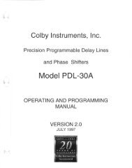
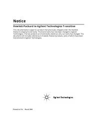
<strong>WCI</strong>-H,7000 and <strong>WCI</strong>-H10,000 <strong>Power</strong>-<strong>Pak</strong> Schematic<br />
HYD. FILTER<br />
1<br />
HIGH PRESSURE<br />
PUMP<br />
AIR PILOT<br />
SWITCH<br />
RESERVIOR<br />
LOW PRESSURE<br />
PUMP<br />
AIR<br />
IN<br />
AIR FILTER<br />
DRAIN<br />
BOELUBE<br />
PUMP<br />
C<br />
L<br />
2<br />
S<br />
PRESSURE<br />
GAGE<br />
HYDRAULIC<br />
MANIFOLD<br />
DUMP<br />
VALVE<br />
MANIFOLD<br />
S L C<br />
PULLER<br />
TO<br />
PULLER<br />
LUBE<br />
OUT<br />
SIGNAL<br />
IN<br />
HYDRAULIC PUMP SCHEMATIC<br />
1<br />
2<br />
<strong>WCI</strong>-H7,000<br />
<strong>WCI</strong>-H10,000<br />
SPLIT MANDREL SYSTEM ONLY<br />
HIGH PRESSURE LINES<br />
LOW PRESSURE LINE<br />
AIR LINES<br />
OM-PS-9303-2<br />
14900 Whitman Avenue North Tel: (206) 365-7513<br />
Seattle, Washington 98133 Fax: (206) 365-7483
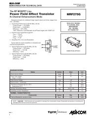
DTL# QTY DETAIL NAME<br />
1 1 PUMP ASSEMBLY<br />
2 1 NIPPLE<br />
3 1 DUMP VALVE<br />
4 1 RESERVOIR<br />
5 1 BOELUBE PUMP<br />
6 1 MUFFLER<br />
7 1 AIR FILTER<br />
8 2 CASTERS (S)<br />
9 2 CASTERS (R)<br />
10 1 BASE PLATE<br />
11 1 FRAME<br />
12 1 COVER<br />
13 1 HYD FILTER<br />
14 1 S-C-L BLOCK<br />
15 1 PIPE BRACKET<br />
16 2 SET SCREW<br />
17 3 FITTING<br />
19 2 BRACKET<br />
20 2 BRACKET<br />
21 1 RESERVOIR FILL<br />
22 1 PRESSURE GAGE<br />
23 1 RING<br />
24 1 PIPE<br />
25 1 MANIFOLD<br />
26 6 FITTING<br />
28 4 FITTING<br />
29 1 HOSE ASSEMBLY<br />
30 1 PUMP<br />
31 A/R TUBING<br />
33 1 FITTING<br />
34 4 FITTING<br />
35 1 HOSE ASSEMBLY<br />
38 2 FITTING<br />
40 1 FITTING<br />
41 2 NIPPLE<br />
43 1 NIPPLE<br />
44 1 COUPLING<br />
46 1 BUSHING<br />
47 2 FITTING<br />
48 2 NIPPLE<br />
49 1 FITTING<br />
50 12 SCREW<br />
51 8 SCREW<br />
52 7 SCREW<br />
53 16 SCREW<br />
55 6 SCREW<br />
56 12 NUT<br />
58 6 NUT<br />
59 20 WASHER<br />
60 8 WASHER<br />
62 1 VALVE<br />
DTL# QTY DETAIL NAME<br />
63 1 Q/D FITTING<br />
64 1 Q/D FITTING<br />
65 1 Q/D FITTING<br />
66 1 Q/D FITTING<br />
68 20 LOCK WASHER<br />
69 11 LOCK WASHER<br />
70 6 LOCK WASHER<br />
71 2 BOLT<br />
72 2 LOCK WASHER<br />
73 2 NUT<br />
76 1 PIPE<br />
77 1 BRACKET<br />
78 2 SCREW<br />
79 1 AIR Q/D<br />
80 1 FITTING<br />
81 1 FITTING<br />
82 1 VALVE ASSEMBLY<br />
83 1 NIPPLE<br />
84 1 PILOT ACUTATOR<br />
85 1 VALVE<br />
86 1 FITTING<br />
87 1 PLUG<br />
88 1 MANIFOLD ASSY<br />
89 1 VALVE ASSY<br />
90 1 MANIFOLD ASSY<br />
92 2 FITTING<br />
93 2 FITTING<br />
94 2 FITTING<br />
95 1 FITTING<br />
96 1 FITTING<br />
97 1 PUMP<br />
98 1 VALVE<br />
99 3 FITTING<br />
100 1 TUBING<br />
103 2 HOSE ASSEMBLY<br />
104 1 FITTING<br />
105 1 FITTING<br />
107 2 PUMP MOUNT<br />
108 1 HOSE ASSEMBLY<br />
109 1 FITTING<br />
110 1 HOSE ASSEMBLY<br />
111 1 FITTING<br />
112 1 FITTING<br />
113 1 FITTING<br />
114 1 PLUG ASSY<br />
115 1 PLUG<br />
116 1 DOWEL PIN<br />
117 1 FUNNEL<br />
118 1 FILL KIT REFURB<br />
119 1 FITTING