Weinschel Programmable Attenuators (Complete ... - Aptec Electronics
Weinschel Programmable Attenuators (Complete ... - Aptec Electronics Weinschel Programmable Attenuators (Complete ... - Aptec Electronics
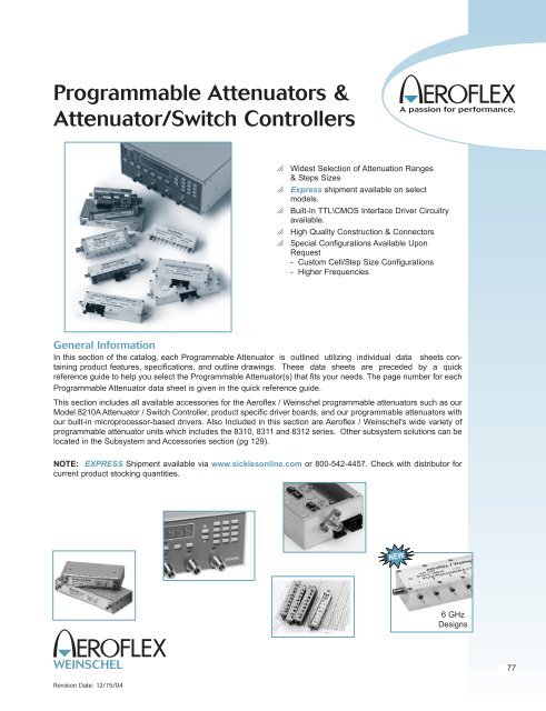
Programmable Attenuators & Attenuator/Switch Controllers o o o o o Widest Selection of Attenuation Ranges & Steps Sizes Express shipment available on select models. Built-In TTL\CMOS Interface Driver Circuitry available. High Quality Construction & Connectors Special Configurations Available Upon Request - Custom Cell/Step Size Configurations - Higher Frequencies General Information In this section of the catalog, each Programmable Attenuator is outlined utilizing individual data sheets containing product features, specifications, and outline drawings. These data sheets are preceded by a quick reference guide to help you select the Programmable Attenuator(s) that fits your needs. The page number for each Programmable Attenuator data sheet is given in the quick reference guide. This section includes all available accessories for the Aeroflex / Weinschel programmable attenuators such as our Model 8210A Attenuator / Switch Controller, product specific driver boards, and our programmable attenuators with our built-in microprocessor-based drivers. Also Included in this section are Aeroflex / Weinschel's wide variety of programmable attenuator units which includes the 8310, 8311 and 8312 series. Other subsystem solutions can be located in the Subsystem and Accessories section (pg 129). NOTE: EXPRESS Shipment available via www.sicklesonline.com or 800-542-4457. Check with distributor for current product stocking quantities. 6 GHz Designs 77 Revision Date: 12/15/04
- Page 2 and 3: Programmable Attenuators Relay Swit
- Page 4 and 5: Programmable Attenuators SOLID-STAT
- Page 6 and 7: Programmable Attenuators Frequently
- Page 8 and 9: Programmable Attenuators Intermodul
- Page 10 and 11: Programmable Attenuators Case Study
- Page 12 and 13: Programmable Attenuators Specificat
- Page 14 and 15: Programmable Attenuators PHYSICAL D
- Page 16 and 17: Programmable Attenuators PHYSICAL D
- Page 18 and 19: Programmable Attenuators Specificat
- Page 20 and 21: Programmable Attenuators Model 3250
- Page 22 and 23: Programmable Attenuators PHYSICAL D
- Page 24 and 25: Programmable Attenuators Models 340
- Page 26 and 27: Programmable Attenuators Models 340
- Page 28 and 29: Programmable Attenuators Model 150T
- Page 30 and 31: Programmable Attenuators ATTENUATIO
- Page 32 and 33: Programmable Attenuators Model 150
- Page 34 and 35: Programmable Attenuators MAXIMUM SW
- Page 36 and 37: Programmable Attenuators 150 Series
- Page 38 and 39: Programmable Attenuators PHYSICAL D
- Page 40 and 41: Programmable Attenuators PHYSICAL D
- Page 42 and 43: Programmable Attenuators PHYSICAL D
- Page 44 and 45: Programmable Attenuators PHYSICAL D
- Page 46 and 47: Programmable Attenuators Specificat
- Page 48 and 49: Programmable Attenuators Ordering G
- Page 50 and 51: Programmable Attenuators Specificat
<strong>Programmable</strong> <strong>Attenuators</strong> &<br />
Attenuator/Switch Controllers<br />
o<br />
o<br />
o<br />
o<br />
o<br />
Widest Selection of Attenuation Ranges<br />
& Steps Sizes<br />
Express shipment available on select<br />
models.<br />
Built-In TTL\CMOS Interface Driver Circuitry<br />
available.<br />
High Quality Construction & Connectors<br />
Special Configurations Available Upon<br />
Request<br />
- Custom Cell/Step Size Configurations<br />
- Higher Frequencies<br />
General Information<br />
In this section of the catalog, each <strong>Programmable</strong> Attenuator is outlined utilizing individual data sheets containing<br />
product features, specifications, and outline drawings. These data sheets are preceded by a quick<br />
reference guide to help you select the <strong>Programmable</strong> Attenuator(s) that fits your needs. The page number for each<br />
<strong>Programmable</strong> Attenuator data sheet is given in the quick reference guide.<br />
This section includes all available accessories for the Aeroflex / <strong>Weinschel</strong> programmable attenuators such as our<br />
Model 8210A Attenuator / Switch Controller, product specific driver boards, and our programmable attenuators with<br />
our built-in microprocessor-based drivers. Also Included in this section are Aeroflex / <strong>Weinschel</strong>'s wide variety of<br />
programmable attenuator units which includes the 8310, 8311 and 8312 series. Other subsystem solutions can be<br />
located in the Subsystem and Accessories section (pg 129).<br />
NOTE: EXPRESS Shipment available via www.sicklesonline.com or 800-542-4457. Check with distributor for<br />
current product stocking quantities.<br />
6 GHz<br />
Designs<br />
77<br />
Revision Date: 12/15/04
<strong>Programmable</strong> <strong>Attenuators</strong><br />
Relay Switched <strong>Programmable</strong> <strong>Attenuators</strong>, Basic Models . . . DC-6 GHz<br />
Frequency Attenuation Step Insertion Maximum Connector Average Peak<br />
Model Range Range Size Loss, Max. SWR Type Power Power Page<br />
Number (GHz) (dB) (dB) (dB) (Watts) (Watts) No.<br />
3200-1 dc-2.0 0-127 1 4.75 1.25-1.35* SMA 1 50 87<br />
3200-2 0-63.75 0.25 4.75 1.25-1.35*<br />
3201-1 0-31 1 3.75 1.25<br />
3201-2 0-120 10 3.75 1.25<br />
3205-1 0-70 10 3.30 1.25<br />
3205-2 0-55 5 3.30 1.25<br />
3205-3 0-1.5 0.1 3.30 1.25<br />
3206-1 0-63 1 4.00 1.25<br />
3209-1 0-64.5 0.1 6.70 1.35<br />
3200-1E dc-3.0 0-127 1 4.90 1.25-1.40* SMA 1 50 87<br />
3200-2E 0-63.75 0.25 4.90 1.25-1.40*<br />
3201-1E 0-31 1 3.40 1.25-1.40*<br />
3205-3E 0-1.5 0.1 3.40 1.25-1.40*<br />
3206-1E 0-63 1 3.70 1.25-1.35*<br />
3209-1E 0-64.5 0.1 5.50 1.35-1.45*<br />
3250-63 dc-1.0 0-63 1 4.75 1.20-1.30* BNC 1 50 96<br />
(75 Ω)<br />
3406-55 dc-6.0 0-55 1 3.80 130 SMA 1 50 100<br />
3408-55.75 0-55.75 0.25 5.00<br />
3408-103 0-103 1<br />
(New)<br />
Relay Switched <strong>Programmable</strong> <strong>Attenuators</strong>, with built-in Microprocessor-Base Driver . . .<br />
DC-3 GHz (For use with Aeroflex / <strong>Weinschel</strong> 8210A Controller)<br />
Frequency Attenuation Step Insertion Maximum Connector Average Peak<br />
Model Range Range Size Loss, Max. SWR Type Power Power Page<br />
Number (GHz) (dB) (dB) (dB) (Watts) (Watts) No.<br />
3200T-1 dc-2.0 0-127 1 4.75 1.25-1.35* SMA 1 50 93<br />
3200T-2 0-63.75 0.25 4.75 1.25-1.35*<br />
3201T-1 0-31 1 3.75 1.25<br />
3201T-2 0-120 10 3.75 1.25<br />
3201T-4 0-1.2 0.1 3.30 1.25<br />
3205T-1 0-70 10 3.30 1.25<br />
3205T-2 0-55 5 3.30 1.25<br />
3205T-3 0-1.5 0.1 3.30 1.25<br />
3206T-1 0-63 1 4.00 1.25<br />
3209T-1 0-64.5 0.1 6.70 1.35<br />
3200T-1E dc-3.0 0-127 1 4.90 1.20-1.40* SMA 1 50 93<br />
3200T-2E 0-63.75 0.25 4.90 1.20-1.40*<br />
3201T-1E 0-31 1 3.40 1.20-1.40*<br />
3205T-3E 0-1.5 0.1 3.40 1.20-1.40*<br />
3206T-1E 0-63 1 3.70 1.25-1.35*<br />
3209T-1E 0-64.5 0.1 5.50 1.35-1.45*<br />
3250T-63 dc-1.0 0-63 1 4.75 1.20-1.30* BNC 1 50 96<br />
(75 Ω)<br />
3406T-55 dc-6.0 0-55 1 3.80 130 SMA 1 50<br />
3408T-55.75 0-55.75 0.25 5.00<br />
3408T-103 0-103 1<br />
(New)<br />
* VARIES WITH FREQUENCY.<br />
78<br />
EXPRESS Shipment available via www.sicklesonline.com or 800-542-4457.<br />
Check with Distributor for other available models.<br />
5305 Spectrum Drive, Frederick, MD 21703-7362 TEL: 301-846-9222, 800-638-2048 Fax: 301-846-9116<br />
web: www.aeroflex-weinschel.com email: sales@aeroflex-weinschel.com<br />
Revision Date: 12/11/05
<strong>Programmable</strong> <strong>Attenuators</strong><br />
Relay Switched <strong>Programmable</strong> <strong>Attenuators</strong>, with built-in Microprocessor-Based Driver . . .<br />
dc - 26.5 GHz (For use with Aeroflex / <strong>Weinschel</strong> 8210A Controller)<br />
Frequency Attenuation Step Insertion Maximum Connector Average Peak<br />
Model Range Range Size Loss, Max. SWR Type Power Power Page<br />
Number (GHz) (dB) (dB) (dB) (Watts) (Watts) No.<br />
150T-11 dc-18.0 0-11 1 2.2 1.50-1.90* 3.5mm 1 100 102<br />
150T-15 0-15 1 2.2 1.50-1.90*<br />
150T-31 0-31 1 2.6 1.50-1.90*<br />
150T-62 0-62 2 2.6 1.50-1.90*<br />
150T-70 0-70 10 2.6 1.35-1.70*<br />
150T-75 0-75 5 2.2 1.50-1.90*<br />
150T-110 0-110 10 2.2 1.50-1.90*<br />
151T-11 dc-4.0 0-11 1 0.9 1.50 3.5mm 1 100 102<br />
151T-15 0-15 1 0.9 1.50<br />
151T-31 0-31 1 0.9 1.50<br />
151T-62 0-62 2 1.1 1.50<br />
151T-70 0-70 10 0.7 1.35<br />
151T-75 0-75 5 0.9 1.50<br />
151T-110 0-110 10 0.9 1.50<br />
152T-55 dc-26.5 0-55 5 2.98 1.40-1.80* 3.5mm 1 100 102<br />
152T-70 0-70 10 2.98 1.40-1.80*<br />
152AT-70 0-70 10 2.98 1.40-1.80*<br />
152T-90 0-90 10 2.98 1.40-1.80*<br />
Relay Switched <strong>Programmable</strong> <strong>Attenuators</strong>, Basic Models . . . dc - 26.5 GHz<br />
Frequency Attenuation Step Insertion Maximum Connector Average Peak<br />
Model Range Range Size Loss, Max. SWR Type Power Power Page<br />
Number (GHz) (dB) (dB) (dB) (Watts) (Watts) No.<br />
150-11 dc-18.0 0-11 1 2.2 1.50-1.90* 3.5mm 1 100 106<br />
150-15 0-15 1 2.2 1.50-1.90*<br />
150-31 0-31 1 2.6 1.50-1.90*<br />
150-70 0-70 10 2.6 1.35-1.70*<br />
150-75 0-75 5 2.2 1.50-1.90*<br />
150-110 0-110 10 2.2 1.50-1.90*<br />
151-11 dc-4.0 0-11 1 0.9 1.50 3.5mm 1 100 106<br />
152-90 dc-26.5 0-90 10 2.98 1.40-1.80* 3.5mm 1 100 106<br />
* VARIES WITH FREQUENCY.<br />
EXPRESS Shipment available via www.sicklesonline.com or 800-542-4457.<br />
Check with Distributor for other available models.<br />
79<br />
5305 Spectrum Drive, Frederick, MD 21703-7362 TEL: 301-846-9222, 800-638-2048 Fax: 301-846-9116<br />
web: www.aeroflex-weinschel.com email: sales@aeroflex-weinschel.com<br />
Revision Date: 12/15/04
<strong>Programmable</strong> <strong>Attenuators</strong><br />
SOLID-STATE PROGRAMMABLES . . . to 3 GHz<br />
Frequency Attenuation Step Insertion Maximum Average<br />
Model Range Range Size Loss, Max. SWR Power Connector Page<br />
Number (GHz) (dB) (dB) (dB) Type No.<br />
4216-63 0.8-2.3 0-63 1 3.40 150 +28 dBm SMA 111<br />
4218-63.75 0-63.75 0.25 4.90 150<br />
4218-127 0-127 1 4.90 150<br />
4226-63 0.8-3.0 0-63 1 3.75 1.50 +28 dBm SMA 113<br />
4228-63.75 0.8-2.5 0-63.75 0.25 4.50 1.50<br />
4228-103 0.8-3.0 0-103 1 5.50 1.50<br />
(New)<br />
4238-63.75 0-63.75 0.25 9.00 1.60 +30 dBm SMA 115<br />
4238-103 103 1 9.00<br />
(New)<br />
4246-63 10 MHz-2.5 0-63 1 10.00 2.00 +36 dBm SMA 117<br />
4248-63.75 0-63.75 0.25 13.00<br />
4248-103 103/1 13.00<br />
(New)<br />
EXPRESS Shipment available via www.sicklesonline.com or 800-542-4457.<br />
Check with Distributor for other available models.<br />
80<br />
5305 Spectrum Drive, Frederick, MD 21703-7362 TEL: 301-846-9222, 800-638-2048 Fax: 301-846-9116<br />
web: www.aeroflex-weinschel.com email: sales@aeroflex-weinschel.com<br />
Revision Date: 12/15/04
<strong>Programmable</strong> <strong>Attenuators</strong><br />
ATTENUATOR UNITS & CONTROLLERS. . . dc to 26.5 GHz, 100 Watts<br />
<strong>Programmable</strong>/Switch Controllers:<br />
(pg 126-128)<br />
The Model 8210A Attenuator / Switch Controller provides a<br />
flexible, low cost solution for the control and operation of<br />
electromechanical switches and programmable step attenuators<br />
using standard communication interfaces. The 8210A<br />
represents a new concept in device control applications for<br />
bench test and subsystem designs.<br />
o Designed to interface with Aeroflex / <strong>Weinschel</strong>’s line<br />
of programmable attenuators (3200T & 150T) and<br />
other electromechanical devices.<br />
o<br />
o<br />
Simplifies your bench test setups<br />
and subsystem design.<br />
Available in two standard<br />
communication interfaces:<br />
- Model 8210A-1:GPIB/IEEE-488 (HS-488 ready)<br />
- Model 8210A-2:RS-232, RS-422, RS-485<br />
Each model contains similar capabilities and provides<br />
switch-selectable parameters to tailor the interface’s<br />
operation.<br />
100 W Hot-Switchable High Power<br />
Attenuator Unit:<br />
(pages 123-125)<br />
o Available in 0-15 dB or<br />
0-31 dB Configurations<br />
o DC to 13 GHz<br />
Operation<br />
o Power Handling up to 100 Watts average<br />
o High Accuracy & repeatability<br />
o IEEE-488 & Standard Serial Interfaces<br />
o Relative vs. Nominal attenuation step function.<br />
o Bus Controlled <strong>Programmable</strong> Attenuator Units<br />
<strong>Programmable</strong> Attenuator Units for Rack<br />
or Bench Use:<br />
(Pages 119-122)<br />
Aeroflex / <strong>Weinschel</strong>'s 8310 &<br />
8311 Series <strong>Programmable</strong><br />
Attenuator Units represent<br />
Aeroflex / <strong>Weinschel</strong>'s newest<br />
concept in programmable<br />
attenuation for bench test and<br />
subsystem applications.<br />
Standard 8310 Series designs house and control various<br />
Aeroflex / <strong>Weinschel</strong> <strong>Programmable</strong> Attenuator Models<br />
(3200T, 150T, and 4200 Series via front panel controls or<br />
standard communications interfaces including GPIB (IEEE-<br />
488) and RS-232/RS-422/RS485. The standard units<br />
combine the features of the Aeroflex / <strong>Weinschel</strong> 8210A<br />
Device Controller with a front panel user interface to form a<br />
flexible, easy to use solution.<br />
Most 8310 Series are single channel configurations where<br />
RF signal is routed through either the front or rear mounted<br />
Ports A & B but can be configured for up to four channels of<br />
attenuation, RF switching, or other functions and other features<br />
such as:<br />
o Multi-Channel attenuation paths (up to 4 input/<br />
outputs).<br />
o Relative vs. Nominal attenuation step function.<br />
o Wide choice of Frequency & Attenuation Ranges.<br />
- dc to 1, 2, 3, 18 & 26.5 GHz<br />
- up to 127 dB<br />
- Solid-State (GaAs FET & PIN)<br />
- Relay Switched<br />
- 50 & 75 Ω Configurations<br />
o High Accuracy & Repeatability.<br />
o Easily mounted into racks or cabinets designed per<br />
EIA RS-310 or MIL-STD-189.<br />
81<br />
5305 Spectrum Drive, Frederick, MD 21703-7362 TEL: 301-846-9222, 800-638-2048 Fax: 301-846-9116<br />
web: www.aeroflex-weinschel.com email: sales@aeroflex-weinschel.com<br />
Revision Date: 12/15/04
<strong>Programmable</strong> <strong>Attenuators</strong><br />
Frequently Asked Questions about <strong>Programmable</strong> <strong>Attenuators</strong>....<br />
What are the applications of Aeroflex / <strong>Weinschel</strong><br />
programmable attenuators?<br />
Aeroflex / <strong>Weinschel</strong>'s programmable attenuators are used<br />
to control the power of radio frequency and microwave signals.<br />
Applications include control of input power to signal<br />
measuring systems, control of output power from signal<br />
generating systems, adjustment power for BIT error rate<br />
testing, controlling losses in a signal path and simulating the<br />
signal fading of a microwave communication system....to<br />
name just a few.<br />
How do they work?<br />
Aeroflex / <strong>Weinschel</strong>'s programmable attenuators consist of<br />
a series of attenuation pads (cells) that are selectively<br />
inserted into the signal path via a control signal. An example<br />
is a series of cells such as 1, 2, 4, 8 and 16 dB arranged<br />
in a binary sequence. Such an attenuator is called a binary<br />
attenuator. Combinations of cells are switched "on" to provide<br />
attenuation steps from 0 dB to 31 dB. Another example<br />
is a unit having cell values of 10, 20 and 40 dB which will<br />
provide 10 dB steps between 0 dB and 70 dB.<br />
How are the attenuators switched?<br />
The basic structure of a programmable attenuator is shown<br />
below. There are several ways the attenuator pads are<br />
switched in and out of the RF path. Aeroflex / <strong>Weinschel</strong>'s<br />
3200 series uses TO-5 can relay switches. These are useful<br />
up to 2.0 GHz and higher. Aeroflex / <strong>Weinschel</strong>'s 150<br />
series operate up to 26.5 GHz and utilize reed switches<br />
housed within a precision machined cavity.<br />
Aeroflex / <strong>Weinschel</strong> also manufactures programmable<br />
attenuators using solid state switching that offers faster<br />
switching speeds but their frequency range is more limited<br />
than mechanical step attenuators. Whereas mechanically<br />
switched attenuators operate from DC to their maximum frequency,<br />
solid state attenuators have a lower frequency limit.<br />
Solid state attenuators also have lower isolation between<br />
control and through path.<br />
How fast do the attenuators switch?<br />
Switching speed of mechanically switched attenuators is<br />
typically between 6 and 35 msec. This is the maximum time<br />
between the application of the switching command to the<br />
cell and the cessation of contact bounce. This time is a function<br />
of switch structure and size.<br />
What is a latching and<br />
non-latching attenuator?<br />
Non-latching is also called<br />
momentary or fail-safe. For<br />
the non-latching type, the<br />
attenuator is switched to the<br />
attenuation "on" position only<br />
so long as control power is applied<br />
to the switch. As soon as power is<br />
removed the switch reverts to it passive<br />
state or fail-safe state...usually the zero dB state. In latching<br />
attenuators each cell stays in the last setting even if power<br />
is removed. Latching attenuators have two control lines.<br />
One control line causes the attenuator to switch to the<br />
"attenuation on" setting while the other control line causes<br />
the attenuator to switch to the zero dB setting. There is normally<br />
a permanent magnet that holds the switch stable in<br />
either position.<br />
Each version has its advantages and disadvantages. The<br />
non-latching switch requires constant power to the solenoid<br />
when in the "on" position. On the other hand the latching<br />
version requires greater switch current to overcome it's permanent<br />
magnet.<br />
How are the attenuators controlled?<br />
The Model 3200 & 3400 Series non-latching attenuators<br />
require only one 12 volt control line per cell. The direction of<br />
control current is not important.<br />
The Model 150 Series is a latching version using one positive<br />
5 volt or 24 volt common return line and two grounding<br />
control lines.<br />
In order for switching to be guaranteed the voltage between<br />
common and control must be held within specified limits.<br />
Power supply regulation must be kept within range even<br />
while heavy switching current is being drawn. Any cable<br />
voltage drops must be added to the minimum control voltage<br />
to obtain the required power supply voltage at the<br />
attenuator.<br />
Aeroflex / <strong>Weinschel</strong>'s programmable attenuators, such as<br />
the Model 3200T, 3400T and 150T Series feature on-board<br />
TTL drivers. TTL driver boards are also available for the<br />
Model 150 Series attenuators.<br />
82<br />
5305 Spectrum Drive, Frederick, MD 21703-7362 TEL: 301-846-9222, 800-638-2048 Fax: 301-846-9116<br />
web: www.aeroflex-weinschel.com email: sales@aeroflex-weinschel.com<br />
Revision Date: 12/20/05
<strong>Programmable</strong> <strong>Attenuators</strong><br />
What is the switch life of these programmable<br />
attenuators?<br />
Specified life for mechanical switches is normally in the<br />
range of 1 to 10 million switching. This specification is per<br />
switch, independent of the other switches in the attenuator.<br />
For the Model 150 series attenuators the specification is 5<br />
million cycles, i.e. one cycle is the switch moving in both<br />
directions. These specifications are based on the mechanical<br />
life of the switch, however, other factors have an impact<br />
on attenuator life. High power operation can have an<br />
adverse effect on the switch contact surfaces. This can<br />
reduce the overall life of the switch by causing the attenuator<br />
performance to go outside it's specification.<br />
What is monotonicity?<br />
A programmable step attenuator is considered monotonic if<br />
it's attenuation always increases when it is commanded to<br />
increase. This applies on a per frequency basis. For<br />
instance the 20 dB setting at 1 GHz will always be less than<br />
the 21 dB setting at 1 GHz. This does not necessarily mean<br />
that the 20 dB setting at 1 GHz will always be less than the<br />
21 dB setting 18 GHz. Monotonicity is influenced by the<br />
SWR of the individual attenuator cells as the cells are combined<br />
to form an attenuation value. It is also influenced by<br />
the summation of individual cell attenuation tolerances as<br />
the cells are combined.<br />
What is the difference between insertion loss and<br />
incremental attenuation?<br />
<strong>Programmable</strong> attenuators have insertion loss and also<br />
incremental attenuation. Insertion loss is the loss through<br />
the attenuator when all cells are switched to zero dB. It is<br />
the residual loss of the device itself. Insertion loss usually<br />
increases with frequency reaching several dB at the higher<br />
frequencies and generally has very flat frequency response.<br />
Incremental attenuation is the attenuation values of the<br />
attenuators cells relative to the insertion loss. Since insertion<br />
loss is always present, the performance of a<br />
programmable attenuator is always given as incremental<br />
attenuation relative to insertion loss. Insertion loss is considered<br />
part of the fixed performance of the system path in<br />
which the programmable attenuator is located.<br />
What is the advantages of <strong>Attenuators</strong> with built-in<br />
driver circuitry?<br />
These attenuators feature an internal microcontroller-based<br />
driver that provides a TTL-level digital interface for control<br />
of the attenuator relays (Figure 1). This card simplifies<br />
operation and interfacing requirements, while at the same<br />
time providing for greatly enhanced flexibility over past<br />
designs. User-selectable modes of operation include both<br />
parallel and serial bus. The parallel mode provides a simple,<br />
one-bit per relay on/off control with internal pullups for<br />
use primarily in single attenuator applications. This mode<br />
allows the attenuator to be controlled via a variety of<br />
methods, such as a TTL-level digital output port, or<br />
mechanical toggle switches. The serial mode provides a<br />
two-wire serial bus structure and protocol for connecting a<br />
number of devices to a single host control interface, suitable<br />
for use in larger system and sub-system applications. The<br />
built-in driver contains non-volatile configuration memory<br />
that is used to hold a wide variety of attenuator and driverdependent<br />
parameters, including serial number, attenuator<br />
cell dB values, relay configurations, and switching requirements,<br />
which are all accessible via the digital interface. This<br />
frees the system designer from such low-level details, allowing<br />
faster integration. In either operational mode, the<br />
microcontroller enters an idle condition during periods of<br />
inactivity, turning off all on-board clocks, reducing EMI concerns,<br />
and lowering power consumption. On-board<br />
regulation for the digital circuitry allows the programmable<br />
attenuator to operate from a single input supply voltage.<br />
TTL/CMOS<br />
Compatible<br />
Digital Interface<br />
+12 to<br />
+15 V<br />
Input<br />
EMI<br />
Filters<br />
Single-Chip<br />
Microcontroller<br />
+5 V<br />
Regulator<br />
Relay<br />
Drivers<br />
Figure 1. Digital Driver Circuitry<br />
Non-Volatile<br />
Configuration<br />
Memory<br />
To<br />
Attenuator<br />
Relays<br />
How can I control the <strong>Attenuators</strong> with built-in drivers?<br />
The communications interface (Model 8210A) provides a<br />
flexible, low cost solution for the operation of programmable<br />
step attenuators and other electromechanical devices<br />
under computer control. Designed to interface to Aeroflex /<br />
<strong>Weinschel</strong>’s line of programmable attenuators built-in intelligent<br />
drivers, the Model 8210A represents a new concept in<br />
device control applications for bench test and subsystem<br />
designs. The 8210A communications interface provides a<br />
high-level interface from various industry standard communications<br />
interfaces, including IEEE-488 and RS232<br />
/RS422/RS485, to the programmable attenuators serial<br />
Driver Interface Bus.<br />
83<br />
5305 Spectrum Drive, Frederick, MD 21703-7362 TEL: 301-846-9222, 800-638-2048 Fax: 301-846-9116<br />
web: www.aeroflex-weinschel.com email: sales@aeroflex-weinschel.com<br />
Revision Date: 12/15/04
<strong>Programmable</strong> <strong>Attenuators</strong><br />
Intermodulation Distortion in <strong>Programmable</strong> <strong>Attenuators</strong>....<br />
<strong>Weinschel</strong> has been a major supplier of<br />
programmable attenuators to the RF industry for over<br />
25 years. Historically the most demanding specifications<br />
for these components have been low insertion loss and SWR,<br />
combined with a reasonable life expectancy of several million<br />
switching cycles. This was usually adequate for RF instruments<br />
like spectrum analyzers and signal generators, wherein the<br />
attenuator bandwidth rather than the switching speed was of prime<br />
concern. To achieve wide bandwidths the programmable attenuators<br />
were mostly of electromechanical design and the linearity of<br />
these passive components was not only assumed but never<br />
questioned by any customer. Intermodulation distortion discussions<br />
and problems were usually limited to components such as<br />
amplifiers, mixers and filters.<br />
In recent years, however, wireless communication systems<br />
employing complex digital modulation schemes, increased channel<br />
capacity, high transmit power and extremely low receiver<br />
sensitivity have put into question the linearity of passive components.<br />
Even very low level multi-tone intermodulation products<br />
generated by attenuators can seriously degrade the efficiency of<br />
a system/ instrument if these products fall within the user passband.<br />
For two closely spaced tones at frequencies f1 and f2, the<br />
third order IM products at 2f1 - f2 and 2f2 - f1 , are the most<br />
harmful distortion products. They are harmful because they are<br />
located close to f1 and f2 and virtually impossible to filter out. In<br />
today's base stations the multicarrier power amplifier (MCPA) is<br />
replacing banks of single-channel amplifiers and their corresponding<br />
power combining network. MCPAs have the capability<br />
of carrying a number of modulation schemes simultaneously and<br />
can also employ schemes such as dynamic-channel-allocation<br />
(DCA) to use the allocated frequency spectrum more efficiently.<br />
The in-band intermodulation distortion (IMD) performance of<br />
these amplifiers is extremely critical and needs to be measured<br />
using low distortion programmable multi-tone generators whose<br />
IMD performance must be quite superior. This is discussed in the<br />
two case studies cited here.<br />
Electromechanical programmable attenuators obviously<br />
provide a far superior IMD performance than<br />
their corresponding solid state<br />
counterparts employing semiconductor<br />
switching elements.<br />
However, their slow switch speed, in the order of milliseconds,<br />
and short switch life in the order of 5-10 million cycles<br />
make them unattractive in some applications like cell phone testing<br />
and other ATE systems. Solid State programmable attenuators<br />
do overcome these two problems and are therefore included here<br />
for IMD performance comparison. It is not the intent of this brief<br />
article to go into the theory of intermodulation distortion. The goal<br />
here is to provide some good basic IMD test data for a<br />
variety of commercial programmable attenuators and let the end<br />
user select the most appropriate type for his application.<br />
Measurement System and Parameters...<br />
All test data presented here was generated using a<br />
commercially available Passive IM Analyzer, Summitek Model<br />
SI-800A which provides a fully integrated system for characterizing<br />
distortion produced by cables, attenuators and other passive<br />
devices. Although the system is capable of measuring both,<br />
through and reflected IM3, IM5, IM7 and IM9, the focus here is<br />
only on through IM for the most troublesome third order product,<br />
IM3. To carry out a meaningful comparison between different<br />
attenuators all measurements were carried out using two equal<br />
amplitude input tones at 869 MHz (f1) and 891 MHz(f2) , the IM3<br />
frequency being 847 MHz (2f1-f2). Input carrier power was<br />
stepped in increments of 1 dB from -7dBm to +27dBm. All external<br />
adapters and cables were carefully selected to maintain the<br />
system's residual IM level of around -120 dBm. Although the system<br />
permitted receiver measurements between -70 to -120 dBm<br />
we restricted all measurements between -85 to -110 dBm by<br />
using a calibrated low IM coupler and attenuators at the output<br />
port of the DUT. One must be aware that the accuracy of such<br />
small signal measurements can easily be off by 2 to 3 dB so<br />
restricting the measurement dynamic range helps reduce the<br />
receiver non-linearity error. Measurements were done over several<br />
days to ensure stability and repeatability.<br />
Distortion Comparison for Basic Types of<br />
<strong>Programmable</strong> <strong>Attenuators</strong>...<br />
The programmable attenuators discussed here are the<br />
switched type with a discrete number of `cells'. Switching<br />
between the zero and attenuate state on each cell is achieved by<br />
a DPDT switch configuration. The cell values are usually in a<br />
binary sequence. For example a 6 cell/6 bit unit could have 1, 2,<br />
4, 8, 16 and 32 dB sections providing a 63 dB dynamic range in<br />
1dB increments. Four basic families of programmable attenuators<br />
are compared, each family being identified by the switch<br />
element used to achieve the transfer from zero to attenuate state.<br />
For the purposes of distortion comparison it was deemed<br />
necessary to select units with similar electrical length and/or<br />
programmability. Both the electromechanical units, TO5 relay<br />
and edge-line type, had an electrical length of about 20 cms. The<br />
two solid state units had 6 cell programmability yielding 63 dB in<br />
1 dB step size. All IM3 vs Pin measurements were done with the<br />
attenuators programmed to be in their characteristic zero insertion<br />
loss state. The zero state was selected because it<br />
generated the highest IM3 levels. The graph below shows the<br />
84<br />
5305 Spectrum Drive, Frederick, MD 21703-7362 TEL: 301-846-9222, 800-638-2048 Fax: 301-846-9116<br />
web: www.aeroflex-weinschel.com email: sales@aeroflex-weinschel.com<br />
Revision Date: 12/15/04
<strong>Programmable</strong> <strong>Attenuators</strong><br />
obvious compromise in IMD performance for the two solid state<br />
types. It is worth noting that the IM3 vs Pin slope is not exactly<br />
3:1 as would be the case in a perfect third order device. The theoretical<br />
two tone third order intercept point, IP3, commonly used<br />
as a figure of merit for comparing linearity is shown in the following<br />
table at two different input power levels. The input IP3 is<br />
derived from the following relation:<br />
Input IP3 = 3(Pin-α)-IM3 + α<br />
2<br />
where α = zero insertion loss of each unit @ 847 MHz, the IM3 frequency.<br />
IM3 and Pin are selected from Table 1.<br />
TABLE 1. SPECIFICATION COMPARISONS:<br />
Attenuator Type<br />
Parameter PIN FET Relay Edge-Line<br />
IP3 @ 42.0 dBm 48.0 dBm 72 dBm 98 dBm*<br />
10 dBm<br />
IP3 @ 39.0 dBm 53.5 dBm 75 dBm 98 dBm<br />
24dBm<br />
I. Loss 2.0 dB 5.0 dB 1.5 dB 0 dB<br />
Switching 2 µsec 2 µsec 5 msec 20 msec<br />
Time<br />
Switch Life ∞ ∞ 10 million 5 million<br />
Frequency 0.8-2.3 0.01-2.5 dc-3 dc-26.5<br />
(GHz)<br />
* NOTE: Although the actual IM3 was not measurable the curve for the edge-line<br />
unit is linear and predictable unlike the two curves for the solid state attenuators. If<br />
we were to extrapolate this curve we would get the same IP3 figure of +98dBm as<br />
expected.<br />
IM3 Performance of Electromechanical & Solid State<br />
<strong>Programmable</strong> <strong>Attenuators</strong><br />
Through IM3 (dBm)<br />
0<br />
-10<br />
-20<br />
-30<br />
-40<br />
-50<br />
-60<br />
-70<br />
-80<br />
-90<br />
-100<br />
-110<br />
-120<br />
-130<br />
-140<br />
-150<br />
Passive IM3 Measurement<br />
<strong>Weinschel</strong> Series 4206, 4216, 3200 & 150<br />
Low Carrier Frequency: 869.0 MHz<br />
High Carrier Frequency: 891.0 MHz<br />
IM3 Frequency:<br />
847.0 MHz<br />
PIN switched - 4216 series<br />
FET switched - 4206 series<br />
TO5 rela y switched - 3200 series<br />
Edge-line reed switched 150 series<br />
-7 -6 -5 -4 -3 -2 -1 0 1 2 3 4 5 6 7 8 9 1011 121314 151617 18192021 222324 252627<br />
Input Power, P in<br />
(dBm) each tone<br />
85<br />
5305 Spectrum Drive, Frederick, MD 21703-7362 TEL: 301-846-9222, 800-638-2048 Fax: 301-846-9116<br />
web: www.aeroflex-weinschel.com email: sales@aeroflex-weinschel.com<br />
Revision Date: 12/15/04
<strong>Programmable</strong> <strong>Attenuators</strong><br />
Case Study 1<br />
Company A offers its IMD series Phase Aligned 8 tone generators<br />
to test intermodulation distortion in multi-carrier power<br />
amplifiers. The output level of these generators is accurately controlled<br />
using a <strong>Weinschel</strong> TO5 relay based programmable<br />
attenuator offering over 60 dB dynamic range. Eight +13 dBm<br />
carriers are input to the attenuator. In MCPAs with feedforward<br />
correction, in-band IMD levels could be as low as -75 dBc so<br />
Company A wanted at least -85 dBc at the output of their generator.<br />
The first problem was that <strong>Weinschel</strong> could not simulate the<br />
exact test conditions. This was readily resolved by establishing a<br />
good co-relation between our two tone IM3 measurement and<br />
Company A's 8 tone test. Having employed the best plating techniques<br />
and using good low IM connector design the attenuator<br />
was still short of the required IMD spec. The final improvement<br />
was achieved by extensive testing on relays from three different<br />
manufacturers. Figure 2 shows IM3 plots of the two best performers.<br />
Manufacturer B consistently provided a 4 to 5 dB<br />
improvement at the two tone level at Pin of +22 dBm and higher.<br />
This corresponded to an acceptable output distortion level for the<br />
Company A generator.<br />
IM3 (dBm)<br />
-65<br />
-75<br />
-85<br />
-95<br />
-105<br />
-115<br />
Case Study 2<br />
Input Power vs. Through IM3 Level<br />
Case Study 1<br />
Passive IM3 Measurement<br />
<strong>Weinschel</strong> 3200-1 with TO5 relays from two different manufacturers<br />
Low Carrier Frequency: 869.0 MHz<br />
High Carrier Frequency: 891.0 MHz<br />
IM3 Frequency:<br />
847.0 MHz<br />
Manufacturer A<br />
Manufacturer B<br />
10 11 12 13 14 15 16 17 18 19 20 21 22 23 24 25 26 27<br />
Input Power, P in (dBm) each tone<br />
Company B manufactures ultra low distortion multi-tone signal<br />
generators. Their units offer up to 160 channels from 5 MHz<br />
through 1 GHz. Each carrier can be leveled as high as +10 dBm.<br />
One of their most stringent requirements is a cross modulation<br />
test. The Company B generator specification is -100 dB below the<br />
sideband of a 100% amplitude modulated carrier, which is -110<br />
dBc. The actual components used in the critical path had to<br />
measure -120 dBc or better. Their generator needed an ultra linear<br />
attenuator to provide a programmed output level in 0.5 dB<br />
increments. Relay based units were tested and found to be unacceptable.<br />
The high performance edge-line attenuators were<br />
expected to solve the problem but at first they too fell short, but<br />
mainly in their zero attenuation state, which generates maximum<br />
distortion. Prior to supplying these units to Company B no customer<br />
had asked for a distortion specification on these supposedly<br />
passive attenuators. Environmental performance had warranted<br />
the use of nickel underplate on the edge lines. This was disclosed<br />
to the customer and suspected to be the prime cause of high IMD<br />
levels. Since the unit was going to be mounted in a benign environment,<br />
elimination of the nickel underplate was not thought to<br />
be a problem. Figure 3 demonstrates the tremendous reduction in<br />
IM3 levels upon elimination of the nickel underplate-a significant<br />
40 dB! A further 10-15 dB improvement was achieved by<br />
redesigning the connectors to reduce their passive IMD. The IM<br />
improvement in these connectors would have served no purpose<br />
prior to the elimination of nickel. This is because the main source<br />
of distortion lay behind the connector back plane, along the edge<br />
transmission line, which had a far greater electrical length than<br />
the two connectors.<br />
IM3 (dBm)<br />
-60<br />
-70<br />
-80<br />
-90<br />
-100<br />
-110<br />
-120<br />
-130<br />
-140<br />
Gold plated edge-line with Ni underplate<br />
Input Power vs. Through IM3 Level<br />
Case Study 2<br />
Passive IM3 Measurement<br />
<strong>Weinschel</strong> 150 Series High Frequency Edge-Line <strong>Programmable</strong> Attenuator<br />
Low Carrier Frequency: 869.0 MHz<br />
High Carrier Frequency: 891.0 MHz<br />
IM3 Frequency:<br />
847.0 MHz<br />
Gold plated edge-line without Ni underplate<br />
Final design with low IM connectors<br />
-7 -6 -5 -4 -3 -2 -1 0 1 2 3 4 5 6 7 8 9 10 11 12 13 14 15 16 17 18 19 20 21 22 23 24 25 26 27<br />
InputPower, P in (dBm)each Tone<br />
Conclusion<br />
Abundant intermodulation test data for four families of programmable<br />
attenuators has been presented in an easy format,<br />
together with their other key performance features. This should<br />
enable instrument and system designers to select the most suitable<br />
type for their application.<br />
The two case studies have also demonstrated that an OEM<br />
component supplier cannot possibly simulate the different distortion<br />
test scenarios of every customer. Such tests would be<br />
extremely varied, complex and cost prohibitive. The IM analyzer<br />
used at <strong>Weinschel</strong> was indeed a narrow band instrument and one<br />
might be concerned about the unit's performance at other frequencies.<br />
This is a legitimate concern for the solid state types, in<br />
which the distortion mechanism is a strong function of the operating<br />
frequency. For the broadband electromechanical types this is<br />
not a major issue. However, with a meaningful two tone intermodulation<br />
measurement it is quite possible to get an excellent<br />
correlation with the customer's test conditions and thereby come<br />
up with a corresponding specification under the two tone test. It<br />
is helpful though, to be able to replicate the total power level that<br />
the unit would be subjected to in the field.<br />
Author: Jimmy Dholoo, VP Engineering @ Aeroflex / <strong>Weinschel</strong><br />
© April 1999, Wireless Design & Development<br />
86<br />
5305 Spectrum Drive, Frederick, MD 21703-7362 TEL: 301-846-9222, 800-638-2048 Fax: 301-846-9116<br />
web: www.aeroflex-weinschel.com email: sales@aeroflex-weinschel.com<br />
Revision Date: 12/15/04
<strong>Programmable</strong> <strong>Attenuators</strong><br />
Model 3200 Series<br />
Model 3200 (E Series)<br />
<strong>Programmable</strong> <strong>Attenuators</strong><br />
with optional TTL Interface<br />
dc to 2.0 GHz<br />
dc t0 3.0 GHz<br />
1 Watt<br />
E<br />
Features<br />
X P R E S S<br />
www.sicklesonline.com<br />
800-542-4457<br />
o Widest Selection of Attenuation Ranges & Step<br />
Sizes<br />
o Available Express Models: 3200-1, 3200-1E-2<br />
3200-2, 3200-2E-2<br />
3201-1, 3201-2<br />
3206-1<br />
Other models may be available for Express delivery.<br />
o High Quality Construction & Connectors<br />
o Special Configurations Available Upon Request<br />
- Custom Cell/Step Size Configurations<br />
- 3.0 GHz and Higher Frequencies<br />
Description<br />
The 3200 Series <strong>Programmable</strong> Step <strong>Attenuators</strong> are<br />
designed for use in automatic test equipment and OEM<br />
systems operating in the dc to 3 GHz frequency range. This<br />
series is available in many standard attenuation ranges and<br />
cell configurations. Custom designed configurations are<br />
available upon request. Each cell contains a double-pole,<br />
double-throw relay that provides a zero path or attenuated<br />
path for the RF signal.<br />
Microstrip circuitry and special compensation techniques<br />
produce flat attenuation versus frequency characteristics.<br />
The microstrip construction, using thick-film circuit elements,<br />
ensures product uniformity. To minimize RF<br />
leakage, the 3200 Series <strong>Attenuators</strong> are provided with<br />
gold-plated contact areas and feedthrough filters at each<br />
control terminal.<br />
Specifications<br />
NOMINAL IMPEDANCE: 50 Ω<br />
FREQUENCY RANGE:<br />
dc to 2.0 GHz: 3200-1, 3200-2, 3201-1, 3201-2, 3205-1,<br />
3205-2, 3205-3, 3206-1, 3209-1<br />
dc to 3.0 GHz: 3200-1E, 3200-2E, 3201-1E, 3205-3E,<br />
3206-1E, 3209-1E<br />
CELL CONFIGURATIONS:<br />
Model NO. Attenuation Cell<br />
Number Cells Range/Steps Increments<br />
(dB)<br />
(dB)<br />
3200-1 8 127/1 1, 2, 4, 8, 16, 32, 64*<br />
3200-1E<br />
3200-2 8 63.75/0.25 0.25, 0.5, 1, 2, 4, 8,<br />
3200-2E 16, 32<br />
3201-1 5 31/1 1, 2, 4, 8, 16<br />
3201-1E<br />
3201-2 5 120/10 10, 20, 30, 60**<br />
3205-1 4 70/10 10, 20, 20, 20<br />
3205-2 4 55/5 5, 10, 20, 20<br />
3205-3 4 1.5/0.1 0.1, 0.2, 0.4, 0.8<br />
3205-3E<br />
3206-1 6 63/1 1, 2, 4, 8, 16, 32<br />
3206-1E<br />
3209-1 10 64.5/0.1 0.1, 0.2, 0.4, 0.8, 1,<br />
3209-1E 2, 4, 8, 16, 32<br />
*64 dB cell comprised of two 32 dB cells<br />
*60 dB cell comprised of two 30 dB cells<br />
MAXIMUM SWR:<br />
Freq 3200-1 3200-1E 3201-X 3206-1E 3209-1 3209-1E<br />
Range 3200-2 3200-2E 3205-X<br />
(GHz) 3201-1E 3206-X<br />
3205-3E<br />
dc - 0.2 1.30 1.25 1.30 1.25 1.35 1.35<br />
0.2 - 1 1.25 1.25 1.25 1.25 1.35 1.35<br />
1 - 2 1.35 1.25 1.35 1.25 1.35 1.35<br />
2 - 3 - - - 1.40 - - - 1.35 - - - 1.45<br />
INCREMENTAL ATTENUATION ACCURACY:<br />
Frequency<br />
Accuracy<br />
Range (GHz)<br />
dc - 0.5 + 0.2 dB or 0.5%<br />
0.5 - 1 + 0.2 dB or 1.0%<br />
1 -3 + 0.3 dB or 2.0%<br />
MONOTONICITY: dc to 3.0 GHz<br />
INCREMENTAL TEMPERATURE COEFFICIENT:<br />
30 and 32 dB Cells: 0.00005 dB/dB/°C<br />
All other cells:<br />
0.00002 dB/dB/°C<br />
POWER RATING: 1 watt average to 25°C ambient<br />
temperature, derated linearly to 0.25 watt @ 71°C. 50 watts<br />
peak (5 µsec pulse width; 1% duty cycle)<br />
87<br />
5305 Spectrum Drive, Frederick, MD 21703-7362 TEL: 301-846-9222, 800-638-2048 Fax: 301-846-9116<br />
web: www.aeroflex-weinschel.com email: sales@aeroflex-weinschel.com<br />
Revision Date: 12/15/04
<strong>Programmable</strong> <strong>Attenuators</strong><br />
Specifications - Con’t<br />
MAXIMUM INSERTION LOSS (dB):<br />
Frequency 3200-1 3200-1E 3201-1 3205-X 3201-1E 3205-3E 3206-1 3206-1E 3209-1 3209-1E<br />
Range (GHz) 3200-2 3200-2E 3201-2<br />
dc - 0.5 2.80 2.20 1.80 1.80 1.50 1.25 2.00 1.50 3.50 3.00<br />
0.5 - 1.0 3.50 3.00 2.40 2.30 1.80 1.75 2.70 2.00 4.50 3.50<br />
1.0 - 1.5 4.25 3.20 3.00 2.80 2.25 2.25 3.30 2.50 5.60 4.00<br />
1.5 - 2.0 4.75 3.70 3.75 3.30 2.50 2.50 4.00 2.80 6.70 4.50<br />
2.0-3.0 - - - 4.90 - - - - - - 3.40 3.40 - - - 3.70 - - - 5.50<br />
88<br />
POWER COEFFICIENT:
<strong>Programmable</strong> <strong>Attenuators</strong><br />
TTL DRIVER SPECIFICATIONS:<br />
INTERFACE CONNECTOR: Option -1(Models 3200, 3201,<br />
3205 and 3206): 10 pin .025 square post header on .1<br />
center, mates with Amp connector 746285-1 or equivalent.<br />
Option -1 (3209): 14 pin .025 square post header on .1<br />
center, mates with Amp connector 746285-2 or equivalent.<br />
Option -2: 15 pin D Socket Connector, mates with Cannon<br />
connector DA-15S or equivalent.<br />
INPUT VOLTAGE: VIN High= +2.0V minimum<br />
+5.0V typical<br />
Vcc maximum<br />
VIN Low = 0 minimum<br />
0.8 maximum<br />
INPUT CURRENT: IIN (V IN =2.4 V) = 55 µA<br />
IIN (V IN =3.85 V) = 280 µA<br />
SUPPLY CURRENT (Digital Section): ICC=25.0 mA<br />
maximum<br />
SUPPLY CURRENT (per cell continuos): ICC=25.0 mA<br />
maximum for 2 GHz models and 30 mA per cell for 3 GHz<br />
models.<br />
SUPPLY VOLTAGE: VCC=+12.0 to +15V<br />
TEMPERATURE RANGE (Operating): -40°C to +70°C<br />
MODELS WITH BUILT-IN DRIVERS: Most 3200s are available<br />
with an intelligent interface\driver cards. These are<br />
designed to interface with our 8210A Series Controllers<br />
which greatly simplifies computer control applications. Refer<br />
to Model 3200T and 3201T data sheet for more information.<br />
PHYSICAL DIMENSIONS:<br />
Aeroflex / Wein<br />
Model No. No. Cells A B C D<br />
3200-X 8 101.6 (4.0 7 EQ SPCS @ 10.16 (.40) = 71.1 (2.80) 88.9 (3.50) 95.2 (3.75)<br />
3201-X 5/4 76.2 (3.00) 4 EQ SPCS @ 10.16 (.40) = 40.64 (1.60) 63.5 (2.50) 69.8 (2.75)<br />
3205-X 4 58.9 (2.32) 3 EQ SPCS @ 10.16 (.40) = 30.5 (1.20) 46.2 (1.82) 52.6 (2.07)<br />
3206-X 6 81. 3+0.5 5 EQ SPCS @ 10.16 (.40) = 50.8 (2.00) 68.6 (2.70) 75.18 (2.96)<br />
(3.20+0.02<br />
NOTE:<br />
All dimensions are given in mm (inches) and are maximum, unless otherwise specified.<br />
89<br />
5305 Spectrum Drive, Frederick, MD 21703-7362 TEL: 301-846-9222, 800-638-2048 Fax: 301-846-9116<br />
web: www.aeroflex-weinschel.com email: sales@aeroflex-weinschel.com<br />
Revision Date: 12/15/04
<strong>Programmable</strong> <strong>Attenuators</strong><br />
PHYSICAL DIMENSIONS:<br />
TTL OPTION -1 (3200, 3201, 3206):<br />
Model No. E<br />
3200-X-1 37.8 (1.49)<br />
3201-X-1 18.8 (0.74)<br />
3206-X-1 18.8 (0.74)<br />
TTL OPTION -1 (3205):<br />
Aeroflex / <strong>Weinschel</strong><br />
Control Connector J3 Pin Locations:<br />
TTL Conn 3200-1-1 3200-2-1 3201-1-1 3201-2-1 3205-1-1 3205-2-1 3205-3-1 3206-1-1<br />
PIN No. (J3) dB (Cell) dB (Cell) dB (Cell ) dB (Cell) dB (Cell) dB (Cell) dB (Cell ) dB (Cell)<br />
1 32 0.25 NC NC NC NC NC NC<br />
2 1 0.5 NC NC NC NC NC NC<br />
3 2 1 1 30 NC NC NC 1<br />
4 32* 2 2 10 10 5 0.1 2<br />
5 4 4 4 30** 20 10 0.2 4<br />
6 8 8 8 20 20 20 0.4 8<br />
7 16 16 16 30** 20 20 0.8 16<br />
8 32* 32 NC NC NC NC NC 32<br />
9 COM COM COM COM COM COM COM COM<br />
10 +Vcc +Vcc +Vcc +Vcc + Vcc + Vcc +Vcc + Vcc<br />
*64 dB cell comprised of two 32 dB cells<br />
**60 dB cell comprised of two 30 dB cells<br />
NC = Not Connected<br />
90<br />
NOTE: All dimensions are given in mm (inches) and are maximum, unless otherwise specified.<br />
5305 Spectrum Drive, Frederick, MD 21703-7362 TEL: 301-846-9222, 800-638-2048 Fax: 301-846-9116<br />
web: www.aeroflex-weinschel.com email: sales@aeroflex-weinschel.com<br />
Revision Date: 12/15/04
<strong>Programmable</strong> <strong>Attenuators</strong><br />
PHYSICAL DIMENSIONS:<br />
TTL Driver Option -2 (3200, 3201, 3205):<br />
Model No. A<br />
3200-X-2 101.6 (4.00)<br />
3201-X-2 76.2 (3.00)<br />
3205-X-2 76.2 (3.00)<br />
Control Connector J3 Pin Locations:<br />
"D" Conn 3200-1-2 3200-2-2 3201-1-2 3201-2-2 3205-1-2 3205-2-2 3205-3-2 Cable (P/N 101-1805)<br />
PIN No. (J3) dB (Cell) dB (Cell) dB (Cell ) dB (Cell) dB (Cell) dB (Cell) dB (Cell) Color Code<br />
1 32 32 NC NC NC NC NC BRN<br />
2 16 16 NC NC NC NC NC YEL<br />
3 8 8 NC NC NC NC NC GRN<br />
4 4 4 16 30** 20 20 0.8 LT BLU<br />
5 32 0.25 1 30** NC NC NC VIO<br />
6 1 0.5 2 10 10 5 0.1 GRY<br />
7 2 1 4 30 20 10 0.2 WHT<br />
8 32* 2 8 20 20 20 0.4 WHT/BLK<br />
9 NC NC NC NC NC NC NC RED<br />
10 GND GND GND GND GND GND GND BLK<br />
11 NC NC NC NC NC NC NC - - -<br />
12 NC NC NC NC NC NC NC - - -<br />
13 NC NC NC NC NC NC NC - - -<br />
14 NC NC NC NC NC NC NC - - -<br />
15 +Vcc +Vcc +Vcc +Vcc +Vcc +Vcc +Vcc ORN<br />
*64 dB cell comprised of two 32 dB cells<br />
**60 dB cell comprised of two 30 dB cells<br />
NC = Not Connected<br />
NOTE:<br />
All dimensions are given in mm (inches) and are maximum, unless otherwise specified.<br />
91<br />
5305 Spectrum Drive, Frederick, MD 21703-7362 TEL: 301-846-9222, 800-638-2048 Fax: 301-846-9116<br />
web: www.aeroflex-weinschel.com email: sales@aeroflex-weinschel.com<br />
Revision Date: 12/15/04
<strong>Programmable</strong> <strong>Attenuators</strong><br />
PHYSICAL DIMENSIONS:<br />
Model 3209-1:<br />
Model 3209-1-1 (TTL Option -1):<br />
92<br />
NOTE: All dimensions are given in mm (inches) and are maximum, unless otherwise specified.<br />
5305 Spectrum Drive, Frederick, MD 21703-7362 TEL: 301-846-9222, 800-638-2048 Fax: 301-846-9116<br />
web: www.aeroflex-weinschel.com email: sales@aeroflex-weinschel.com<br />
Revision Date: 12/15/04
<strong>Programmable</strong> <strong>Attenuators</strong><br />
Model 3200T<br />
Model 3200T (E Series)<br />
<strong>Programmable</strong> <strong>Attenuators</strong><br />
with built-in Microprocessor-Based Driver<br />
dc to 2.0 GHz<br />
dc to 3.0 GHz<br />
1 Watt<br />
For Use with <strong>Weinschel</strong> 8210A Controller<br />
E<br />
Features<br />
X P R E S S<br />
www.sicklesonline.com<br />
800-542-4457<br />
o Widest Selection of Attenuation Ranges<br />
& Steps Sizes<br />
o Available Express Models: 3200T-1<br />
3206T-1<br />
Other models may be available for Express delivery.<br />
o Built-In TTL\CMOS Interface Driver Circuitry<br />
o High Quality Construction and Connectors<br />
o Special Configurations Available Upon Request<br />
- Custom Cell/Step Size Configurations<br />
- 3.0 GHz and Higher Frequencies<br />
Description<br />
This line of intelligent programmable step attenuators with a<br />
built-in digital interface are designed to simplify the control<br />
and integration of these devices into subsystem and bench<br />
applications. This series of <strong>Programmable</strong> Step <strong>Attenuators</strong><br />
is designed for use in automatic test equipment and OEM<br />
systems operating in the dc to 3 GHz frequency range.<br />
These models are available in many standard attenuation<br />
ranges and cell configurations. Each cell contains a doublepole,<br />
double-throw relay that provides a minimum loss or<br />
attenuated path for the RF signal.<br />
Microstrip circuitry and special compensation techniques<br />
produce flat attenuation versus frequency characteristics.<br />
The microstrip construction, using thick-film circuit<br />
elements, ensures product uniformity. To minimize RF leakage,<br />
the 3200T Series <strong>Attenuators</strong> are provided with<br />
gold-plated contact areas and feedthrough filters at each<br />
control terminal.<br />
Specifications<br />
NOMINAL IMPEDANCE: 50 Ω<br />
FREQUENCY RANGE:<br />
dc to 2.0 GHz: 3200T-1, 3200T-2, 3201T-1, 3201T-2,<br />
3205T-1, 3205T-2, 3205T-3, 3206T-1,<br />
3209T-1<br />
dc to 3.0 GHz: 3200T-1E, 3200T-2E, 3201T-1E,<br />
3205T-3E, 3206T-1E, 3209T-1E<br />
CELL CONFIGURATIONS:<br />
Model NO. Attenuation Cell<br />
Number Cells Range/Steps Increments<br />
(dB)<br />
(dB)<br />
3200T-1 8 127/1 1, 2, 4, 8, 16, 32, 64*<br />
3200T-1E<br />
3200T-2 8 63.75/0.25 0.25, 0.5, 1, 2, 4, 8,<br />
3200T-2E 16, 32<br />
3201T-1 5 31/1 1, 2, 4, 8, 16<br />
3201T-1E<br />
3201T-2 5 120/10 10, 20, 30, 60**<br />
3205T-1 4 70/10 10, 20, 20, 20<br />
3205T-2 4 55/5 5, 10, 20, 20<br />
3205T-3 4 1.5/0.1 0.1, 0.2, 0.4, 0.8<br />
3205T-3E<br />
3206T-1 6 63/1 1, 2, 4, 8, 16, 32<br />
3206T-1E<br />
3209T-1 10 64.5/0.1 0.1, 0.2, 0.4, 0.8, 1,<br />
3209T-1E 2, 4, 8, 16, 32<br />
*64 dB cell comprised of two 32 dB cells<br />
**60 dB cell comprised of two 30 dB cells<br />
MAXIMUM SWR:<br />
Freq 3200T-1 3200T-1E 3201T-X 3201T-1E 3209T-1 3209T-1E<br />
Range 3200T-2 3200T-2E 3205T-X 3205T-3E<br />
(GHz) 3206T-X 3206T-1E<br />
dc - 0.2 1.30 1.25 1.30 1.25 1.35 1.35<br />
0.2 - 1 1.25 1.25 1.25 1.25 1.35 1.35<br />
1 - 2 1.35 1.25 1.35 1.25 1.35 1.35<br />
2 - 3 - - - 1.40 - - - 1.35 - - - 1.45<br />
INCREMENTAL ATTENUATION ACCURACY:<br />
Frequency<br />
Accuracy<br />
Range (GHz)<br />
dc - 0.5 + 0.2 dB or 0.5%<br />
0.5 - 1 + 0.2 dB or 1.0%<br />
1 -3 + 0.3 dB or 2.0%<br />
MONOTONICITY: dc to 3.0 GHz<br />
INCREMENTAL TEMPERATURE COEFFICIENT:<br />
30 and 32 dB Cells: 0.00005 dB/dB/°C<br />
All other cells:<br />
0.00002 dB/dB/°C<br />
93<br />
5305 Spectrum Drive, Frederick, MD 21703-7362 TEL: 301-846-9222, 800-638-2048 Fax: 301-846-9116<br />
web: www.aeroflex-weinschel.com email: sales@aeroflex-weinschel.com<br />
Revision Date: 12/15/04
<strong>Programmable</strong> <strong>Attenuators</strong><br />
Specifications - Con’t<br />
MAXIMUM INSERTION LOSS (dB):<br />
Frequency 3200T-1 3200T-1E 3201-1 3205T-X 3201T-1E 3206T-1 3206T-1E 3209T-1 3209T-1E<br />
Range (GHz) 3200T-2 3200T-2E 3201-2 3205T-3E<br />
dc - 0.5 2.80 2.00 1.80 1.80 1.25 2.00 1.50 3.50 3.00<br />
0.5 - 1.0 3.50 2.70 2.40 2.30 1.75 2.70 2.00 4.50 3.50<br />
1.0 - 1.5 4.25 3.00 3.00 2.80 2.25 3.30 2.50 5.60 4.00<br />
1.5 - 2.0 4.75 3.50 3.75 3.30 2.50 4.00 2.80 6.70 4.50<br />
2.0-3.0 - - - 4.30 - - - - - - 3.40 - - - 3.70 - - - 5.50<br />
POWER RATING: 1 watt average to 25°C ambient temperature,<br />
derated linearly to 0.25 watt @ 71°C. 50 watts<br />
peak (5 µsec pulse width; 1% duty cycle)<br />
POWER COEFFICIENT: < 0.005 dB/dB/watt<br />
RATED SWITCH LIFE: 5 million cycles operations per cell<br />
@ 0 dBm<br />
CYCLING RATE: 5 Hz maximum per relay<br />
DRIVER INTERFACE:<br />
Input Supply Voltage: +12.0 to +15. V<br />
Control Signals:<br />
TTL/CMOS compatible<br />
Interface Modes:<br />
parallel / serial<br />
DC Characteristics (at 25 °C):<br />
Parameter<br />
Specification<br />
V IL Low-level input V: -0.5V min, 0.8V max<br />
V IH High-level input V: 2.0V min, 5.25V max<br />
I PU Pullup current 50 µA min, 400 µA max<br />
V IN Supply Voltage: +12.0 to +15.0V<br />
I IN Supply current: 25 mA<br />
(digital section)<br />
I CELL Supply current: 15 mA (2 GHz Units)<br />
(per cell) continuous 30 mA (3 GHz Units)<br />
TEMPERATURE RANGE (Operating): -20°C to +70°C<br />
TEST DATA: Test data is available at additional cost.<br />
CONNECTORS: SMA female connectors per MIL-STD-348<br />
interface dimensions - mate nondestructively with<br />
MIL-C-39012 connectors.<br />
INTERFACE CONNECTOR: 14 pin .025 square post<br />
header on .1 center. Mates with Amp connector 746285-2 or<br />
equivalent.<br />
CONSTRUCTION:<br />
Housing: Aluminum<br />
Connectors: Stainless steel body and beryllium<br />
copper contacts.<br />
WEIGHT: 3200T-X 165 g (8.4 oz)<br />
3201T-X 132 g (7.3 oz)<br />
3205T-X 132 g (7.3 oz)<br />
3206T-X 132 g (7.3 oz)<br />
3209T-X 218 g (9.7 oz)<br />
ACCESSORIES<br />
<strong>Programmable</strong> Attenuator/Switch Controller: The Model<br />
8210A <strong>Programmable</strong> Attenuator/Switch Controller provides<br />
a flexible, low cost solution for the operation of programmable<br />
step attenuators and other electromechanical devices<br />
under computer control. Designed to interface to Aeroflex /<br />
<strong>Weinschel</strong>'s intelligent programmable attenuators, the<br />
8210A represents a new concept in device control applications<br />
for bench test and subsystem designs. The 8210A<br />
provides a high-level interface from various industry standard<br />
communications interfaces, including IEEE-488 and<br />
RS232/RS422/RS485, to the programmable attenuator’s<br />
serial Driver Interface Bus.<br />
CONTROL CONFIGURATION<br />
These programmable attenuators feature an internal microcontroller-based<br />
driver that provides a TTL-level digital<br />
interface for control of the attenuator relays. This card simplifies<br />
operation and interfacing requirements, while at the<br />
same time providing for greatly enhanced flexibility over<br />
past designs. User-selectable modes of operation include<br />
both parallel and serial bus. The parallel mode provides a<br />
simple, one-bit per relay on/off control with internal pullups<br />
for use primarily in single attenuator applications. This mode<br />
allows the attenuator to be controlled via a variety of methods,<br />
such as a TTL-level digital output port, or mechanical<br />
toggle switches. The device bus provides a two-wire serial<br />
bus structure and protocol for connecting a number of<br />
devices to a single host control interface, suitable for use in<br />
larger system and sub-system applications. The digital<br />
interface contains non-volatile configuration memory that is<br />
used to hold a wide variety of attenuator and driver-dependent<br />
parameters, including serial number, attenuator cell dB<br />
values, relay configurations, and switching requirements,<br />
which are all accessible via the digital interface.<br />
In either operational mode, the microcontroller enters an<br />
idle condition during periods of inactivity, turning off all<br />
on-board clocks, reducing EMI concerns, and lowering<br />
power consumption. On-board regulation for the digital<br />
circuitry allows the attenuator to operate from a single input<br />
supply voltage.<br />
94<br />
5305 Spectrum Drive, Frederick, MD 21703-7362 TEL: 301-846-9222, 800-638-2048 Fax: 301-846-9116<br />
web: www.aeroflex-weinschel.com email: sales@aeroflex-weinschel.com<br />
Revision Date: 12/15/04
<strong>Programmable</strong> <strong>Attenuators</strong><br />
PHYSICAL DIMENSIONS:<br />
Model 3200T, 3201T, 3205T, & 3206T:<br />
"D"<br />
Model 3209T:<br />
Model No. No. Cells A B C D<br />
3200T-X 8 101.6 (4.0) 34.8 (1.37) 88.9 (3.50) 95.2 (3.75)<br />
3201T-X 5/4 76.2 (3.00) 22.1 (0.87) 63.5 (2.50) 69.8 (2.75)<br />
3205T-X 4 72.4 (2.85) 20.3 (0.80) 46.2 (1.82) 52.6 (2.07)<br />
3206T-X 6 81. 3+0.5 24.0 (0.98) 68.6 (2.70) 75.18 (2.96)<br />
(3.20+0.02<br />
NOTE:<br />
All dimensions are given in mm (inches) and are maximum, unless otherwise specified.<br />
95<br />
5305 Spectrum Drive, Frederick, MD 21703-7362 TEL: 301-846-9222, 800-638-2048 Fax: 301-846-9116<br />
web: www.aeroflex-weinschel.com email: sales@aeroflex-weinschel.com<br />
Revision Date: 12/15/04
<strong>Programmable</strong> <strong>Attenuators</strong><br />
Model 3250 & 3250T<br />
<strong>Programmable</strong> <strong>Attenuators</strong><br />
with optional TTL Interface<br />
dc to 1.0 GHz<br />
1 Watt<br />
75 Ω<br />
T Series for use with <strong>Weinschel</strong> 8210A Controller<br />
E<br />
Features<br />
X P R E S S<br />
www.sicklesonline.com<br />
800-542-4457<br />
o Cost Effective design for Wireless/Cellular<br />
Applications<br />
o Available Express Models: 3250T-63<br />
Other models may be available for Express delivery.<br />
o Optional Built-in Interface<br />
o Custom Configurations including bus controlled<br />
attenuator subsystems<br />
Specifications<br />
NOMINAL IMPEDANCE: 75 Ω<br />
FREQUENCY RANGE: dc to 1.0 GHz:<br />
MAXIMUM SWR:<br />
Frequency Range (GHz)<br />
SWR<br />
dc - 0.5 1.60<br />
0.5 - 1.0 1.40<br />
CELL CONFIGURATIONS:<br />
Model NO. Attenuation Cell<br />
Number Cells Range/Steps Increments<br />
(dB)<br />
(dB)<br />
3250-63 6 63/1 1, 2, 4, 8, 16, 32<br />
INCREMENTAL ATTENUATION ACCURACY:<br />
Frequency<br />
Accuracy<br />
Range (GHz)<br />
dc - 0.5 + 0.3 dB or 2.0%<br />
0.5 - 1.0 + 0.4 dB or 2.0%<br />
MAXIMUM CHARACTERISTIC ZERO LOSS (dB):<br />
Frequency Range (GHz)<br />
Loss (dB)<br />
dc - 0.5 2.25<br />
0.5 - 1.0 5.00<br />
RATED SWITCH LIFE: 5 million operations per cell (typ)<br />
SWITCHING TIME: 8 msec. maximum @ nominal rated<br />
voltage.<br />
CYCLING RATE: 5 Hz maximum<br />
OPERATING VOLTAGE: +11V to +16V<br />
+12V to +17V (TTL opt -1)<br />
OPERATING CURRENT: 16 mA maximum per cell<br />
TEMPERATURE RANGE (Operating): -40 to +70°C<br />
POWER RATING: 1 watt average, 50 watts peak (5 µsec<br />
pulse width; 1% duty cycle)<br />
CONNECTORS: BNC female connectors per MIL-STD-<br />
348 interface dimensions - mate nondestructively with<br />
MIL-C-39012 connectors.<br />
CONTROL TERMINALS: 0.040 inch. (1 mm) diameter<br />
solderable leads<br />
CONSTRUCTION:<br />
Housing:<br />
Connectors:<br />
Aluminum<br />
Nickel plated brass body and<br />
beryllium copper contacts.<br />
WEIGHT: 3250 140 g (4.5 oz)<br />
3250T 189 g (4.9 oz)<br />
ACCESSORIES<br />
<strong>Programmable</strong> Attenuator/Switch Controller: The Model<br />
8210A <strong>Programmable</strong> Attenuator/Switch Controller provides<br />
a flexible, low cost solution for the operation of programmable<br />
step attenuators and other electromechanical devices<br />
under computer control. Designed to interface to Aeroflex /<br />
<strong>Weinschel</strong>'s intelligent programmable attenuators, the<br />
8210A represents a new concept in device control applications<br />
for bench test and subsystem designs. The 8210A<br />
provides a high-level interface from various industry standard<br />
communications interfaces, including IEEE-488 and<br />
RS232/RS422/RS485, to the programmable attenuator's<br />
serial Driver Interface Bus.<br />
96<br />
5305 Spectrum Drive, Frederick, MD 21703-7362 TEL: 301-846-9222, 800-638-2048 Fax: 301-846-9116<br />
web: www.aeroflex-weinschel.com email: sales@aeroflex-weinschel.com<br />
Revision Date: 12/15/04
<strong>Programmable</strong> <strong>Attenuators</strong><br />
CONTROL CONFIGURATION:<br />
Standard Unit: One terminal is connected to case ground<br />
and the remaining terminals are provided for activation of<br />
individual cells. Attenuation is fail-safe to "0" setting in the<br />
absence of a control voltage. Application of a voltage (+) to<br />
a particular cell causes it to switch to the attenuate position.<br />
Units with TTL Option: Units with this options are supplied<br />
with a very low profile connectorized TTL interface board<br />
mounted directly to the control terminals. This TTL interface<br />
option is available with a 10 pin ribbon cable connector and<br />
is supplied with a mating connector. Refer to Physical<br />
Dimensions for mating connector pin/wiring details. Two<br />
wires are specified for supply voltage and ground. The<br />
remaining wires will accept TTL control signals to activate or<br />
de-activate a particular attenuation cell. A TTL high will<br />
energize a cell to the high attenuation state, whereas a TTL<br />
low will maintain a cell in its zero attenuation state.<br />
To order 3250 Series <strong>Attenuators</strong> with this option add -1 to<br />
basic model number for ribbon cable connector. Example:<br />
Model 3250-63 with a TTL interface would be 3250-63-1.<br />
Note: Control is non-latching and requires a continuous<br />
control signal for the period of time in which attenuation is<br />
required.<br />
TTL DRIVER SPECIFICATIONS:<br />
INTERFACE CONNECTOR: Option -1: 10 pin .025 square<br />
post header on .1 center, mates with Amp connector<br />
746285-1 or equivalent<br />
INPUT VOLTAGE: V IN High= +2.0V minimum<br />
+5.0V typical<br />
Vcc maximum<br />
V IN Low = 0 minimum<br />
0.8 maximum<br />
INPUT CURRENT: I IN (V IN =2.4 V) = 55 µA<br />
I IN (V IN =3.85 V) = 280 µA<br />
SUPPLY CURRENT:<br />
SUPPLY VOLTAGE:<br />
I CC =25 mA maximum per cell<br />
V CC =+12.0 to +15 V<br />
TEMPERATURE RANGE (Operating): -40 to +70 °C<br />
Units with driver Circuitry (Figure 1): Model 3250T-63<br />
features an internal microcontroller-based driver that provides<br />
a TTL-level digital interface for control of the<br />
attenuator relays. This card simplifies operation and interfacing<br />
requirements, while at the same time providing for<br />
greatly enhanced flexibility over past designs. User-selectable<br />
modes of operation include both parallel and serial<br />
bus. The parallel mode provides a simple, one-bit per relay<br />
on/off control with internal pullups for use primarily in single<br />
attenuator applications. This mode allows the attenuator to<br />
be controlled via a variety of methods, such as a TTL-level<br />
digital output port, or mechanical toggle switches. The builtin<br />
driver bus provides a two-wire serial bus structure and<br />
protocol for connecting a number of devices to a single host<br />
control interface, suitable for use in larger system and subsystem<br />
applications. This programmable attenuator<br />
contains non-volatile configuration memory that is used to<br />
hold a wide variety of attenuator and driver-dependent para-<br />
TTL/CMOS<br />
Compatible<br />
Digital Interface<br />
+12 to<br />
+15 V<br />
Input<br />
Figure 1. Built-In Driver Circuitry<br />
meters, including serial number, attenuator cell dB values,<br />
relay configurations, and switching requirements, which are<br />
all accessible via the digital interface.<br />
Digital Driver Interface Specifications:<br />
Input Supply Voltage: +12.0 to +15.0V<br />
Control Signals: TTL/CMOS compatible<br />
Interface Modes: parallel/ I 2 C serial<br />
DC Characteristics (at 25°C):<br />
Digital Interface:<br />
Parameter<br />
Specification<br />
VI L Low Level input: -0.5 min, 0.8V max<br />
V IH High Level input: 2.0 min, 5.25V max<br />
I PU Pullup Current 50 µA min, 400 µA max<br />
Power Supply:<br />
V IN Supply Voltage: +12.0 to +15.0V<br />
I IN Supply current: 25 mA<br />
I CELL Supply Current: 150 mA (per cell, switching)<br />
TEMPERATURE: -20° to +70°C operating<br />
-55° to +85°C nonoperating<br />
INTERFACE CONNECTOR: 14 pin .025 square post<br />
header on .1 center. Mates with Amp connector 746285-2 or<br />
equivalent (one mating connector included with each unit).<br />
MODEL NUMBER DESCRIPTION:<br />
Example:<br />
EMI<br />
Filters<br />
Basic<br />
Model<br />
Number<br />
Single-Chip<br />
Microcontroller<br />
+5 V<br />
Regulator<br />
3250* - XX - X<br />
Attenuation<br />
Value (dB)<br />
Relay<br />
Drivers<br />
Non-Volatile<br />
Configuration<br />
Memory<br />
To<br />
Attenuator<br />
Relays<br />
TTL Option<br />
(Add -1)<br />
Example: 3250-63-1<br />
*Add T to Basic Model Number when ordering Digital Control<br />
Circuitry.<br />
97<br />
5305 Spectrum Drive, Frederick, MD 21703-7362 TEL: 301-846-9222, 800-638-2048 Fax: 301-846-9116<br />
web: www.aeroflex-weinschel.com email: sales@aeroflex-weinschel.com<br />
Revision Date: 12/15/04
<strong>Programmable</strong> <strong>Attenuators</strong><br />
PHYSICAL DIMENSIONS:<br />
Model 3250:<br />
Aeroflex / <strong>Weinschel</strong><br />
BNC CONNECTORS<br />
BOTH ENDS<br />
Model 3250 w/TTL Option -1:<br />
Control Connector J3 Pin Locations:<br />
TTL Conn 3250-63-1<br />
PIN No. (J3) dB (Cell)<br />
1 NC<br />
2 NC<br />
3 32<br />
4 1<br />
5 2<br />
6 4<br />
7 8<br />
8 16<br />
9 COM<br />
10 +Vcc<br />
NC = Not Connected<br />
NOTE:<br />
All dimensions are given in mm (inches) and are maximum, unless otherwise specified.<br />
98<br />
5305 Spectrum Drive, Frederick, MD 21703-7362 TEL: 301-846-9222, 800-638-2048 Fax: 301-846-9116<br />
web: www.aeroflex-weinschel.com email: sales@aeroflex-weinschel.com<br />
Revision Date: 12/15/04
<strong>Programmable</strong> <strong>Attenuators</strong><br />
PHYSICAL DIMENSIONS:<br />
Model 3250T:<br />
BNC CONNECTORS<br />
BOTH ENDS<br />
Aeroflex / <strong>Weinschel</strong><br />
NOTE:<br />
All dimensions are given in mm (inches) and are maximum, unless otherwise specified.<br />
99<br />
5305 Spectrum Drive, Frederick, MD 21703-7362 TEL: 301-846-9222, 800-638-2048 Fax: 301-846-9116<br />
web: www.aeroflex-weinschel.com email: sales@aeroflex-weinschel.com<br />
Revision Date: 12/15/04
<strong>Programmable</strong> <strong>Attenuators</strong><br />
Models 3406 & 3408<br />
<strong>Programmable</strong> <strong>Attenuators</strong><br />
dc to 6.0 GHz<br />
1 Watt<br />
Ideal for Wireless/Test Applications<br />
CELL CONFIGURATIONS:<br />
Model NO. Attenuation Cell<br />
Number Cells Range/Steps Increments<br />
(dB)<br />
(dB)<br />
3406-55 6 55/1 1, 2, 4, 8, 16, 24<br />
Features<br />
o Higher Frequency range to 6 GHz.<br />
o Wide Selection of Attenuation Ranges & Step<br />
Sizes<br />
- 0 to 55 dB in 1 dB steps<br />
- 0 to 103 dB in 1 dB steps<br />
- 0 to 55.75 in 0.25 dB steps<br />
o High Quality Construction & Connectors<br />
o Special Configurations Available Upon Request<br />
Description<br />
The 3400 Series <strong>Programmable</strong> Step <strong>Attenuators</strong> are<br />
designed for use in automatic test equipment and OEM<br />
systems operating in the dc to 6 GHz frequency range. This<br />
series is available in many standard attenuation ranges and<br />
cell configurations. Custom designed configurations are<br />
available upon request. Each cell contains a double-pole,<br />
double-throw relay that provides a zero path or attenuated<br />
path for the RF signal.<br />
Microstrip circuitry and special compensation techniques<br />
produce flat attenuation versus frequency characteristics.<br />
The microstrip construction, using thin-film circuit elements,<br />
ensures product uniformity. To minimize RF<br />
leakage, the 3400 Series <strong>Attenuators</strong> are provided with<br />
gold-plated contact areas and feedthrough filters at each<br />
control terminal.<br />
Specifications<br />
NOMINAL IMPEDANCE: 50 Ω<br />
FREQUENCY RANGE: dc to 6.0 GHz<br />
MAXIMUM SWR:<br />
Frequency Range (GHz)<br />
SWR<br />
dc - 3 1.30<br />
3 - 6 1.45<br />
3408-55.75 8 55.75/0.25 0.25, 0.5, 1, 2, 4, 8,<br />
16, 24<br />
3408-103 8 103/1 1, 2, 4, 8, 16, 24, 48*<br />
*48 dB cell comprised of two 24 dB cells<br />
INCREMENTAL ATTENUATION ACCURACY:<br />
Frequency<br />
Accuracy<br />
Range (GHz)<br />
dc - 3<br />
+0.3 dB or 2% whichever is greater<br />
3 - 6 +0.4 dB or 3% whichever is greater<br />
MAXIMUM INSERTION LOSS (dB):<br />
Frequency 3206-55 3408-55.75<br />
Range (GHz) 3408-103<br />
dc - 3 2.60 3.40<br />
3 - 6 3.80 5.00<br />
MONOTONICITY: dc to 6.0 GHz<br />
POWER RATING: 1 watt average to 25°C ambient temperature,<br />
derated linearly to 0.25 watt @ 70°C. 50 watts<br />
peak (5 μsec pulse width; 1% duty cycle)<br />
POWER COEFFICIENT:
<strong>Programmable</strong> <strong>Attenuators</strong><br />
Specifications - Con’t<br />
CONNECTORS: SMA female connectors per MIL-STD-348<br />
interface dimensions - mate nondestructively with<br />
MIL-C-39012 connectors.<br />
CONTROL TERMINALS: 0.040 inch. (1 mm) diameter<br />
solderable leads. May be used with PC board sockets/<br />
receptacles.<br />
CONSTRUCTION:<br />
Housing: Aluminum<br />
Connectors: Stainless steel body and beryllium<br />
copper contacts.<br />
Control terminals: Brass/Copper, Silver plated<br />
WEIGHT (Typical): 3406-X: 99 g (3.5 oz)<br />
3408-X: 135 g (4.8 oz)<br />
CONTROL CONFIGURATION:<br />
One terminal is connected to case ground and the remaining<br />
terminals are provided for activation of individual cells.<br />
Attenuation is fail-safe to "0" setting in the absence of a control<br />
voltage. Application of a voltage (+) to a particular cell<br />
causes it to switch to the attenuate position.<br />
Note: Control is non-latching and requires a continuous<br />
control signal for the period of time in which attenuation is<br />
required.<br />
PHYSICAL DIMENSIONS:<br />
A<br />
B<br />
Aeroflex / <strong>Weinschel</strong><br />
C<br />
D<br />
Model No. No. Cells A B C D<br />
3408-X 8 136.1 (5.36) 123.4 (4.86) 7 EQ SPCS @ 15.20 (.60) = 106.7 (4.20) 128.5 (5.06)<br />
3406-X 6 105.7 (3.66) 93.0 (3.66) 5 EQ SPCS @ 15.20 (.60) =76.0 (3.00) 98.0 (3.86)<br />
NOTE:<br />
All dimensions are given in mm (inches) and are nominal, unless otherwise specified.<br />
101<br />
5305 Spectrum Drive, Frederick, MD 21703-7362 TEL: 301-846-9222, 800-638-2048 Fax: 301-846-9116<br />
web: www.aeroflex-weinschel.com email: sales@aeroflex-weinschel.com<br />
Revision Date: 12/11/05
<strong>Programmable</strong> <strong>Attenuators</strong><br />
Models 3406T & 3408T<br />
<strong>Programmable</strong> <strong>Attenuators</strong><br />
with built-in Microprocessor-Based Driver<br />
dc to 6.0 GHz<br />
1 Watt<br />
For Use with <strong>Weinschel</strong> 8210A Controller<br />
CELL CONFIGURATIONS:<br />
Model NO. Attenuation Cell<br />
Number Cells Range/Steps Increments<br />
(dB)<br />
(dB)<br />
3406T-55 6 55/1 1, 2, 4, 8, 16, 24<br />
Features<br />
o Higher Frequency range to 6 GHz.<br />
o Wide Selection of Attenuation Ranges & Step<br />
Sizes<br />
- 0 to 55 dB in 1 dB steps<br />
- 0 to 103 dB in 1 dB steps<br />
- 0 to 55.75 in 0.25 dB steps<br />
o High Quality Construction & Connectors<br />
o Built-In TTL\CMOS Interface Driver Circuitry<br />
o Special Configurations Available Upon Request<br />
Description<br />
This line of intelligent programmable step attenuators with a<br />
built-in digital interface are designed to simplify the control<br />
and integration of these devices into subsystem and bench<br />
applications. This series of <strong>Programmable</strong> Step <strong>Attenuators</strong><br />
is designed for use in automatic test equipment and OEM<br />
systems operating in the dc to 6 GHz frequency range.<br />
These models are available in many standard attenuation<br />
ranges and cell configurations. Each cell contains a doublepole,<br />
double-throw relay that provides a minimum loss or<br />
attenuated path for the RF signal.<br />
Microstrip circuitry and special compensation techniques<br />
produce flat attenuation versus frequency characteristics.<br />
The microstrip construction, using thick-film circuit<br />
elements, ensures product uniformity. To minimize RF leakage,<br />
the 3400T Series <strong>Attenuators</strong> are provided with<br />
gold-plated contact areas and feedthrough filters at each<br />
control terminal.<br />
Specifications<br />
NOMINAL IMPEDANCE: 50 Ω<br />
FREQUENCY RANGE: dc to 6.0 GHz<br />
MAXIMUM SWR:<br />
Frequency Range (GHz)<br />
SWR<br />
3408T-55.75 8 55.75/0.25 0.25, 0.5, 1, 2, 4, 8,<br />
16, 24<br />
3408T-103 8 103/1 1, 2, 4, 8, 16, 24, 48*<br />
*48 dB cell comprised of two 24 dB cells<br />
INCREMENTAL ATTENUATION ACCURACY:<br />
Frequency<br />
Accuracy<br />
Range (GHz)<br />
dc - 3<br />
+0.3 dB or 2% whichever is greater<br />
3 - 6 +0.4 dB or 3% whichever is greater<br />
MAXIMUM INSERTION LOSS (dB):<br />
Frequency 3206-55 3408-55.75<br />
Range (GHz) 3408-103<br />
dc - 3 2.60 3.40<br />
3 - 6 3.80 5.00<br />
MONOTONICITY: dc to 6.0 GHz<br />
POWER RATING: 1 watt average to 25°C ambient temperature,<br />
derated linearly to 0.25 watt @ 70°C. 50 watts<br />
peak (5 μsec pulse width; 1% duty cycle)<br />
POWER COEFFICIENT:
<strong>Programmable</strong> <strong>Attenuators</strong><br />
Specifications - Con’t<br />
DRIVER INTERFACE:<br />
Parameter<br />
Specification<br />
V IL Low-level input V: -0.5V min, 0.8V max<br />
V IH High-level input V: 2.0V min, 5.25V max<br />
I PU Pullup current: 50 μA min, 400 μA max<br />
V IN Supply Voltage: +12.0 to +15.0V<br />
I IN Supply current: 25 mA<br />
(digital section)<br />
I CELL Supply current: 16.6 mA @ 12V<br />
PHYSICAL DIMENSIONS:<br />
CONNECTORS: SMA female connectors per MIL-STD-348<br />
interface dimensions - mate nondestructively with<br />
MIL-C-39012 connectors.<br />
INTERFACE CONNECTOR: 14 pin .025 square post<br />
header on .1 center. Mates with Amp connector 746285-2 or<br />
equivalent.<br />
CONSTRUCTION:<br />
Housing: Aluminum<br />
Connectors: Stainless steel body and beryllium<br />
copper contacts.<br />
Control terminals: Brass/Copper, Silver plated<br />
WEIGHT (Typical): 3406T-X: 99 g (3.5 oz)<br />
3408T-X: 135 g (4.8 oz)<br />
“B”<br />
“A”<br />
“C”<br />
“D”<br />
Model No. No. Cells A B C D<br />
3408T-X 8 136.1 (5.36) 123.4 (4.86) 7 EQ SPCS @ 15.20 (.60) = 106.7 (4.20) 128.5 (5.06)<br />
3406T-X 6 105.7 (3.66) 93.0 (3.66) 5 EQ SPCS @ 15.20 (.60) =76.0 (3.00) 98.0 (3.86)<br />
NOTE:<br />
All dimensions are given in mm (inches) and are nominal, unless otherwise specified.<br />
2<br />
5305 Spectrum Drive, Frederick, MD 21703-7362 TEL: 301-846-9222, 800-638-2048 Fax: 301-846-9116<br />
web: www.aeroflex-weinschel.com email: sales@aeroflex-weinschel.com<br />
Revision Date: 12/13/05
<strong>Programmable</strong> <strong>Attenuators</strong><br />
Model 150T<br />
dc to 18.0 GHz<br />
Model 151T<br />
dc to 4.0 GHz<br />
Model 152T<br />
dc to 26.5 GHz<br />
Relay Switched <strong>Programmable</strong> <strong>Attenuators</strong>,<br />
with built-in Microprocessor-Based Driver<br />
For Use with <strong>Weinschel</strong> 8210A Controller<br />
E<br />
Description<br />
Aeroflex / <strong>Weinschel</strong>’s line of intelligent programmable step<br />
attenuators with a built-in TTL interface (Figure 1). These<br />
models are designed to simplify the control and integration<br />
of these devices into subsystem and bench applications.<br />
These intelligent attenuators offer the same long reliable<br />
operation with exceptional accuracy and repeatability as<br />
with our other 150 Series <strong>Programmable</strong> <strong>Attenuators</strong>. They<br />
provide programmable adjustments of RF signal levels in<br />
precise steps of 1 dB, 5 dB, 10 dB, or with custom steps<br />
available. Each attenuator consists of a cascaded assembly<br />
of switched attenuator cells and a internal TTL interface.<br />
TTL/CMOS<br />
Compatible<br />
Digital Interface<br />
X P R E S S<br />
www.sicklesonline.com<br />
800-542-4457<br />
Single-Chip<br />
Microcontroller<br />
Non-Volatile<br />
Configuration<br />
Memory<br />
The attenuator elements located in the attenuator cell are<br />
created by a thin-film process which provides exceptional<br />
long-term stability, low power and temperature coefficients.<br />
This series of step attenuators uses a reed switching structure<br />
that provides rapid switching together with low insertion<br />
loss.<br />
BUILT-IN DRIVER CIRCUITRY: These programmable<br />
attenuators feature an internal microcontroller-based driver<br />
that provides a TTL-level digital interface for control of the<br />
attenuator relays. This card simplifies operation and interfacing<br />
requirements, while at the same time providing for<br />
greatly enhanced flexibility over past designs. User-selectable<br />
modes of operation include both parallel and serial<br />
bus. The parallel mode provides a simple, one-bit per relay<br />
on/off control with internal pullups for use primarily in single<br />
attenuator applications. This mode allows the attenuator to<br />
be controlled via a variety of methods, such as a TTL-level<br />
digital output port, or mechanical toggle switches. The<br />
device bus provides a two-wire serial bus structure and protocol<br />
for connecting a number of devices to a single host<br />
control interface, suitable for use in larger system and subsystem<br />
applications. The driver interface contains<br />
non-volatile configuration memory that is used to hold a<br />
wide variety of attenuator and driver-dependent parameters,<br />
including serial number, attenuator cell dB values,<br />
relay configurations, and switching requirements, which are<br />
all accessible via the digital interface. This frees the system<br />
designer from such low-level details, allowing faster integration.<br />
In either operational mode, the microcontroller<br />
enters an idle condition during periods of inactivity, turning<br />
off all on-board clocks, reducing EMI concerns, and lowering<br />
power consumption. On-board regulation for the digital<br />
circuitry allows the programmable attenuator to operate<br />
from a single input supply voltage.<br />
102<br />
Other features include:<br />
Relay<br />
o Wide Variety of Frequency & Attenuation Ranges<br />
+5 V<br />
Drivers<br />
o Broadband Frequency Coverage<br />
Regulator<br />
o High Accuracy and Repeatability<br />
o Long Life, 5 Million Cycles Per Cell<br />
EMI<br />
DC-DC<br />
o Common 14 pin Interface Connector<br />
Filters<br />
Converter<br />
o Custom Attenuation Ranges<br />
Figure 1. Built-In Driver Circuitry<br />
For additional information on the 150 Series, visit our website @ www.aeroflex-weinschel.com/programmables.htm<br />
+12 to<br />
+15 V<br />
Input<br />
To<br />
Attenuator<br />
Relays<br />
5305 Spectrum Drive, Frederick, MD 21703-7362 TEL: 301-846-9222, 800-638-2048 Fax: 301-846-9116<br />
web: www.aeroflex-weinschel.com email: sales@aeroflex-weinschel.com<br />
Revision Date: 3/23/05
<strong>Programmable</strong> <strong>Attenuators</strong><br />
Specifications<br />
NOMINAL IMPEDANCE: 50 Ω<br />
FREQUENCY RANGE: Model 151T: dc to 4 GHz<br />
Model 150T: dc to 18 GHz<br />
Model 152T: dc to 26.5 GHz<br />
CELL CONFIGURATIONS:<br />
Cell 11 15 31 55 62 70 70 75 90 110<br />
1 1 1 1 5 2 10 10 5 10 10<br />
2 4 8 16 10 32 20 40 40 30 40<br />
3 2 2 2 20 16 20 20 20 20 20<br />
4 4 4 8 20 4 20 -- 10 30 40<br />
5 -- -- 4 -- 8 -- -- -- -- --<br />
DRIVER INTERFACE:<br />
Input Supply Voltage: +12.0 to +15.0V<br />
Control Signals: TTL/CMOS compatible<br />
Interface Modes: parallel / serial<br />
DC Characteristics (at 25 °C):<br />
Digital Interface:<br />
Parameter<br />
Specification<br />
V IL Low Level input: -0.5 min, 0.8V max<br />
V IH High Level input: 2.0 min, 5.25V max<br />
I PU Pullup Current 50 μA min, 400 μA max<br />
Power Supply:<br />
V IN Supply Voltage: +12.0 to +15.0V<br />
I IN Supply current: 25 mA<br />
I CELL Supply Current: 150 mA (per cell, switching)<br />
POWER RATING: 1 watt average, 100 watts peak<br />
(5 μsec pulse width; 0.5% duty cycle)<br />
TEMPERATURE: -20° to +70°C operating<br />
-55° to +85°C nonoperating<br />
TEMPERATURE COEFFICIENT:
<strong>Programmable</strong> <strong>Attenuators</strong><br />
ATTENUATION ACCURACY (+dB with respect to 0 dB reference):<br />
Model 150T/151T/152T-11 & 150T/151T/152T-15:<br />
Frequency<br />
Attenuation Setting (dB)<br />
Range (GHz) 1 2 3 4 5 6 7 8 9 10 11 12 13 14 15<br />
dc-4 0.2 0.2 0.3 0.3 0.3 0.3 0.4 0.4 0.4 0.4 0.5 0.5 0.5 0.5 0.5<br />
4-12.4 0.3 0.3 0.4 0.4 0.5 0.5 0.6 0.6 0.6 0.6 0.7 0.7 0.7 0.7 0.7<br />
12.4-18 0.5 0.6 0.6 0.6 0.6 0.7 0.7 0.7 0.7 0.8 0.8 0.8 0.8 0.8 0.8<br />
18-26.5 0.5 0.6 0.7 0.8 0.9 0.9 0.9 1.0 1.1 1.1 1.1 1.1 1.1 1.1 1.1<br />
Model 150T/151T-75:<br />
Frequency<br />
Attenuation Setting (dB)<br />
Range (GHz) 5 10 15 20 25 30 35 40 45 50 55 60 65 70 75<br />
dc-4 0.2 0.2 0.4 0.4 0.5 0.5 0.7 0.7 0.9 0.9 1.1 1.1 1.2 1.2 1.4<br />
4-12.4 0.3 0.3 0.6 0.6 0.9 0.9 1.2 1.2 1.5 1.5 1.8 1.8 2.1 2.1 2.1<br />
12.4-18 0.4 0.4 0.8 0.8 1.2 1.2 1.6 1.6 2.0 2.0 2.4 2.4 2.8 2.8 2.8<br />
Model 150T/151T-31:<br />
Frequency<br />
Attenuation Setting (dB)<br />
Range (GHz) 1 2 3 4 5 6 7 8 9 10 11 12 13 14 15 16<br />
dc-4 0.2 0.2 0.3 0.3 0.3 0.3 0.4 0.4 0.5 0.4 0.5 0.5 0.5 0.5 0.5 0.5<br />
4-12.4 0.3 0.3 0.4 0.4 0.5 0.5 0.6 0.6 0.7 0.6 0.7 0.7 0.7 0.7 0.7 0.7<br />
12.4-18 0.5 0.5 0.6 0.6 0.6 0.6 0.7 0.7 0.8 0.8 0.8 0.8 0.8 0.8 0.8 0.8<br />
Frequency<br />
Attenuation Setting (dB)<br />
Range (GHz) 17 18 19 20 21 22 23 24 25 26 27 28 29 30 31<br />
dc-4 0.5 0.6 0.6 0.6 0.6 0.6 0.6 0.6 0.7 0.7 0.7 0.7 0.7 0.8 0.8<br />
4-12.4 0.8 0.8 0.9 0.9 0.9 0.9 0.9 0.9 1.1 1.0 1.0 1.0 1.0 1.1 1.1<br />
12.4-18 0.9 0.9 1.0 1.0 1.0 1.0 1.1 1.1 1.2 1.2 1.2 1.2 1.2 1.3 1.3<br />
Model 150T/151T-62:<br />
Frequency<br />
Attenuation Setting (dB)<br />
Range (GHz) 2 4 6 8 10 12 14 16 18 20 22 24 26 28 30 32<br />
dc-4 0.3 0.3 0.3 0.4 0.4 0.5 0.5 0.5 0.5 0.5 0.5 0.5 0.5 0.5 0.6 0.6<br />
4-12.4 0.4 0.4 0.4 0.5 0.5 0.6 0.6 0.6 0.7 0.7 0.7 0.8 0.8 0.8 0.8 0.8<br />
12.4-18 0.5 0.5 0.5 0.6 0.6 0.6 0.8 0.8 0.8 0.8 0.8 1.0 1.0 1.0 1.2 1.2<br />
Frequency<br />
Attenuation Setting (dB)<br />
Range (GHz) 34 36 38 40 42 44 46 48 50 52 54 56 58 60 62<br />
dc-4 0.6 0.6 0.7 0.7 0.7 0.8 0.8 0.8 0.9 0.9 0.9 1.0 1.0 1.0 1.2<br />
4-12.4 1.0 1.0 1.1 1.1 1.3 1.4 1.4 1.4 1.5 1.6 1.6 1.6 1.8 1.8 1.8<br />
12.4-18 1.4 1.4 1.6 1.6 1.8 1.8 2.0 2.0 2.0 2.2 2.2 2.2 2.4 2.4 2.4<br />
Model 150T/151T-70, 150T/151T-110, 152AT-70:<br />
Frequency<br />
Attenuation Setting (dB)<br />
Range (GHz) 10 20 30 40 50 60 70 80 90 100 110<br />
dc-4 0.2 0.3 0.5 0.7 0.9 1.0 1.2 1.4 1.6 1.7 1.9<br />
4-12.4 0.4 0.7 0.9 1.2 1.5 1.8 2.1 2.4 2.7 3.0 3.0<br />
12.4-18 0.4 0.8 1.2 1.6 2.0 2.4 2.8 3.2 3.6 4.0 4.0<br />
18-26.5 0.6 0.7 0.9 1.5 1.6 2.2 2.9 --- --- --- ---<br />
Model 152T-55:<br />
Frequency<br />
Attenuation Setting (dB)<br />
Range (GHz) 5 10 15 20 25 30 35 40 45 50 55<br />
dc-4 0.2 0.3 0.4 0.4 0.4 0.6 0.6 0.7 0.7 0.8 1.0<br />
4-12.4 0.3 0.4 0.5 0.5 0.5 0.7 0.8 0.9 0.9 1.0 1.3<br />
12.4-18 0.4 0.4 0.5 0.5 0.5 0.8 1.0 1.1 1.1 1.2 1.6<br />
18-26.5 0.5 0.5 0.6 0.6 0.6 0.9 1.2 1.4 1.4 1.5 2.0<br />
Model 152T-70, 152T-90:<br />
Frequency<br />
Attenuation Setting (dB)<br />
Range (GHz) 10 20 30 40 50 60 70 80 90<br />
dc-4 0.3 0.5 0.6 0.7 0.8 1.0 1.1 1.1 1.2<br />
4-12.4 0.4 0.5 0.7 0.9 1.0 1.3 1.5 1.6 1.7<br />
12.4-18 0.5 0.6 0.8 1.1 1.2 1.4 1.7 1.8 2.1<br />
18-26.5 0.5 0.6 0.9 1.4 1.5 1.8 2.3 2.4 2.8<br />
104<br />
5305 Spectrum Drive, Frederick, MD 21703-7362 TEL: 301-846-9222, 800-638-2048 Fax: 301-846-9116<br />
web: www.aeroflex-weinschel.com email: sales@aeroflex-weinschel.com<br />
Revision Date: 3/23/05
<strong>Programmable</strong> <strong>Attenuators</strong><br />
PHYSICAL DIMENSIONS:<br />
Models 150T, 151T, & 152T:<br />
DIM A B C<br />
3 cell 83.3 (3.28) 76.2 (3.0) 101.6 (4.00)<br />
4 cell 110.7 (4.36) 103.6 (4.08) 129.2 (5.09)<br />
5 cell 136.1 (5.36) 129.1 (5.08) 154.4 (6.08)<br />
NOTE:<br />
All dimensions are given in mm (inches) and are maximum, unless otherwise specified.<br />
150T Series Ordering Guide...<br />
Frequency Range NO. Attenuator Range/Step Size<br />
Cells 11/1 dB 15/1 dB 31/1 dB 55/5 dB 62/2 dB 70/10 dB 75/5 dB 90/10 dB 110/10 dB<br />
dc-4 GHz 4 151T-11 151T-15 N/A 151T-75 N/A 151T-110<br />
3 151T-70<br />
5 151T-31 151T-62<br />
dc-18 GHz 4 150T-11 150T-15 N/A 150T-75 N/A 150T-110<br />
3 150T-70<br />
5 150T-31 150T-62<br />
dc-26.5 GHz 4 N/A NA N/A 152T-55 NA 152T-70 N/A 152T-90 152T-110<br />
3 152AT-70<br />
EXPRESS Shipment available via www.sicklesonline.com or 800-542-4457.<br />
Other models may be available for Express delivery.<br />
5305 Spectrum Drive, Frederick, MD 21703-7362 TEL: 301-846-9222, 800-638-2048 Fax: 301-846-9116<br />
web: www.aeroflex-weinschel.com email: sales@aeroflex-weinschel.com<br />
Revision Date: 3/23/05<br />
105
<strong>Programmable</strong> <strong>Attenuators</strong><br />
Model 150<br />
dc to 18.0 GHz<br />
Model 151<br />
dc to 4.0 GHz<br />
Model 152<br />
dc to 26.5 GHz<br />
Relay Switched <strong>Programmable</strong> <strong>Attenuators</strong><br />
Description<br />
The Model 150, 151 and 152 <strong>Programmable</strong> Step<br />
<strong>Attenuators</strong> represent the widest variety of programmable<br />
attenuators available. This attenuator design is the result of<br />
an extensive development program and offers long reliable<br />
operation with exceptional accuracy and repeatability.<br />
These attenuators can provide programmable adjustments<br />
of RF signal levels in precise steps of 1 dB, 5 dB, 10 dB, or<br />
with custom steps available. Each attenuator consists of a<br />
cascaded assembly of<br />
switched attenuator cells<br />
(Figure 1). The attenuator<br />
elements located in<br />
the attenuator cell are<br />
created by a thin-film<br />
process which provides<br />
exceptional long-term<br />
stability, low power and<br />
temperature coefficients.<br />
This series uses a reed<br />
switching structure that<br />
provides rapid switching<br />
together with low insertion<br />
loss.<br />
Other features include:<br />
o<br />
o<br />
o<br />
o<br />
E<br />
X P R E S S<br />
www.sicklesonline.com<br />
800-542-4457<br />
Broadband Frequency Coverage<br />
High Accuracy and Repeatability<br />
Long Life, 5 Million Cycles Per Cell<br />
3, 4, and 5 Cell Configurations<br />
Figure 1. Cell Schematic<br />
PROGRAMMABILITY: In each programmable step<br />
Attenuator, solenoids are used to switch the internal resistor<br />
card of each cell into and out of the circuit. The switching is<br />
activated by the application of a negative control voltage to<br />
the desired pin located in the control connector. Once the<br />
cell is switched, the solenoid is magnetically latched into<br />
position and is able to withstand extreme shock and vibration.<br />
Internal circuitry is included to interrupt the coil current<br />
after switching is complete. This reduces power dissipation<br />
even if power is continuously applied. The switching time for<br />
each cell is rated at 20 msec maximum which includes the<br />
contact settling time.<br />
BROADBAND ACCURACY & LOW SWR: The use of<br />
Aeroflex / <strong>Weinschel</strong>'s proprietary thin-film resistor process<br />
provides these programmable step attenuators with a high<br />
degree of accuracy and the lowest possible SWR uncertainty<br />
(refer to specifications for actual values). This thin film<br />
process permits the construction of circuits which are truly<br />
distributed and without stray reactances, even at the higher<br />
microwave frequencies.<br />
RELIABILITY: Each programmable step attenuator is<br />
composed of 3 to 5 (4 in most models) cells. As with all<br />
mechanical designs, usable life becomes a primary concern<br />
to the user. With this in mind Aeroflex / <strong>Weinschel</strong> backs all<br />
these attenuators with a rated switch life of 5 million<br />
operations per cell. Standardized testing is also performed<br />
on each programmable step attenuator over its operating<br />
frequency range by a computer controlled Aeroflex /<br />
<strong>Weinschel</strong> Attenuation Measurement System which is<br />
traceable to NIST standards.<br />
ENVIRONMENTAL: These Model 150 <strong>Programmable</strong> Step<br />
<strong>Attenuators</strong> have undergone an extensive environmental<br />
qualification program and have been subjected to<br />
temperature, shock, vibration, and humidity conditions per<br />
MIL-STD-202F. These programmable step attenuators<br />
operate within these specifications at an ambient<br />
temperature of -20° to +75°C. Operating beyond these<br />
limits will adversely affect the accuracy and could damage<br />
the internal circuitry.<br />
For additional information on the 150 Series, visit our website @ www.aeroflex-weinschel.com/programmables.htm<br />
106<br />
5305 Spectrum Drive, Frederick, MD 21703-7362 TEL: 301-846-9222, 800-638-2048 Fax: 301-846-9116<br />
web: www.aeroflex-weinschel.com email: sales@aeroflex-weinschel.com<br />
Revision Date: 3/23/05
<strong>Programmable</strong> <strong>Attenuators</strong><br />
150 Series Cell Configurations...<br />
Cell 1 Cell 2 Cell 3 Cell 4 Cell 5<br />
ATTN Cells ATTN ATTN ATTN ATTN ATTN<br />
Value No. Bypass Element Bypass Element Bypass Element Bypass Element Bypass Element<br />
11 dB 4 0 dB 1 dB 0 dB 4 dB 0 dB 2 dB 0 dB 4 dB - - - - - -<br />
15 dB 4 0 dB 1 dB 0 dB 8 dB 0 dB 2 dB 0 dB 4 dB - - - - - -<br />
31 dB 5 0 dB 1 dB 0 dB 8 dB 0 dB 2 dB 0 dB 16 dB 0 dB 4 dB<br />
55 dB 4 0 dB 5 dB 0 dB 10 dB 0 dB 20 dB 0 dB 20 dB - - - - - -<br />
70 dB 4 0 dB 10 dB 0 dB 20 dB 0 dB 20 dB 0 dB 20 dB - - - - - -<br />
3 0 dB 10 dB 0 dB 40 dB 0 dB 20 dB - - - - - - - - - - - -<br />
75 dB 4 0 dB 5 dB 0 dB 40 dB 0 dB 20 dB 0 dB 10 dB - - - - - -<br />
90 dB 4 0 dB 10 dB 0 dB 30 dB 0 dB 20 dB 0 dB 30 dB - - - - - -<br />
110 dB 4 0 dB 10 dB 0 dB 40 dB 0 dB 20 dB 0 dB 40 dB - - - - - -<br />
Conn Round 5 6 9 10 7 8 11 12 3 4<br />
PIN # Ribbon 13 2 3 9 11 5 4 10 8 7<br />
Wire Round Violet Yellow Orange Blue Black Green Brown White - - - - - -<br />
Color 3/4 Cell<br />
Round Black White Green Orange Blue WHT/BLK RED/BLK GRN/BLK ORN/BLK BLU/BLK<br />
5 Cell<br />
Ribbon Orange Yellow Blue Brown Purple Black Gray White Orange yellow<br />
Table provides standard attenuation ranges, increments, and cell configurations for all Aeroflex / <strong>Weinschel</strong> <strong>Programmable</strong> Step<br />
<strong>Attenuators</strong> (Models 150, 151, 152, & 152A)<br />
Specifications<br />
NOMINAL IMPEDANCE: 50 Ω<br />
FREQUENCY RANGE: Model 151: dc to 4 GHz<br />
Model 150: dc to 18 GHz<br />
Model 152: dc to 26.5 GHz<br />
OPERATIONAL VOLTAGE: + 24V Nominal (+20V minimum<br />
to +30V maximum) or +5V Nominal (+4V minimum* to<br />
+7V maximum)<br />
*Minimum operating voltage derated to +4.25 V @ 55°C and further<br />
derated to +4.5 V @ 75°C<br />
POWER RATING: 1 watt average, 100 watts peak<br />
(5 μsec pulse width; 0.5% duty cycle)<br />
TEMPERATURE: -20° to +75°C operating<br />
-55° to +85°C nonoperating<br />
TEMPERATURE COEFFICIENT: < 0.0001 dB/dB/°C<br />
POWER SENSITIVITY: < 0.001 dB/dB/ Watt<br />
RATED SWITCH LIFE: 5 million cycles per cell<br />
RF INPUT CONNECTORS: Rugged female 3.5 mm<br />
connectors which mate nondestructively with SMA male<br />
connectors per MIL-STD-39012.<br />
CONTROL CONNECTOR: 12 pin Viking TNP12-101<br />
connector with 5' cable or 14 conductor 16" ribbon cable<br />
with connector (shown below):<br />
Ribbon Cable Models<br />
Round (Viking)Cable Models<br />
SWITCHING TIME: 20 msec (includes settling time)<br />
CYCLING RATE: 4 Hz max per relay<br />
CONTROL PULSE WIDTH: 20 msec (minimum)<br />
SWITCHING CURRENT: 125 mA @ +24V per cell<br />
300 mA @ +5V per cell<br />
REPEATABILITY: +0.01 typical to 18 GHz<br />
+0.05 dB typical to 26.5 GHz<br />
VIBRATION: MIL-STD-202F, Method 204D Cond B<br />
ALTITUDE: MIL-STD-202F, Method 105C Cond B,<br />
50,000 Ft.<br />
SHOCK: MIL-STD -202F, Method 213B Cond B,<br />
except 10G, 6 msec<br />
HUMIDITY: MIL-STD-202F, Method 103B,<br />
Cond. B (96 Hrs. @ 95%, RH)<br />
EMC: Radiated interference is within the requirements of<br />
MIL-STD-461 method RE02, VDE 0871 and CISPR<br />
Publication II.<br />
WEIGHT: 5 Cell 350 g (12 oz)<br />
4 Cell 290 g (9.0 oz)<br />
3 Cell 230 g (8.0 oz)<br />
VOLTAGE/CONNECTOR OPTIONS:<br />
VOLTAGE<br />
MODEL(S)<br />
+ 24 V with 150-XX, 151-XX, 152-XX,<br />
Viking Connector 152A-XX<br />
+ 24 V with 150-XX-1, 151-XX-1, 152-XX-1<br />
Ribbon Cable 152A-XX-1<br />
+ 5 V with 150-XX-2, 151-XX-2, 152-XX-2<br />
Viking Connector 152A-XX-2<br />
+ 5 V with 150-XX-3, 151-XX-3, 152-XX-3<br />
Ribbon Cable 152A-XX-3<br />
5305 Spectrum Drive, Frederick, MD 21703-7362 TEL: 301-846-9222, 800-638-2048 Fax: 301-846-9116<br />
web: www.aeroflex-weinschel.com email: sales@aeroflex-weinschel.com<br />
Revision Date: 3/23/05<br />
107
<strong>Programmable</strong> <strong>Attenuators</strong><br />
MAXIMUM SWR (50 Ω Characteristic Impedance):<br />
Frequency (GHz)<br />
APPLICABLE MODELS dc-4 4-18 18-26.5<br />
151-11, 151-15, 151-31, 1.50 - - - - - -<br />
151-75, 151-110<br />
150-11, 150-15, 150-31, 1.50 1.90 - - -<br />
150-75, 150-110<br />
151-70 (3 cell) 1.35 - - - - - -<br />
150-70 (3 cell) 1.35 1.70 - - -<br />
152A-70 (3 cell) 1.40 1.70 1.80<br />
152-55, 152-70, 152-90 1.40 1.60 1.90<br />
MAXIMUM INSERTION LOSS (dB):<br />
Frequency (GHz)<br />
APPLICABLE MODELS dc-4 4-18 18-26.5<br />
151-11, 151-15, 151-75, 151-110 0.90 - - - - - -<br />
150-11, 150-15, 150-75, 150-110 0.90 2.20 - - -<br />
151-31 (5 cell) 1.10 - - - - - -<br />
150-31 (5 cell) 1.10 2.60* - - -<br />
151-70 (3 cell) 0.70 - - - - - -<br />
150-70 (3 cell) 0.70 1.60 - - -<br />
152A-70 (3 cell) 0.90 2.00 2.98<br />
152-55, 152-70, 152-90 0.90 2.00 2.98<br />
ATTENUATION ACCURACY (+dB with respect to 0 dB reference):<br />
*4-12.4 is 1.80, 12.4-18 is 2.60<br />
Model 150/151/152-11 & 150/151/152-15:<br />
Frequency<br />
Attenuation Setting (dB)<br />
Range (GHz) 1 2 3 4 5 6 7 8 9 10 11 12 13 14 15<br />
dc-4 0.2 0.2 0.3 0.3 0.3 0.3 0.4 0.4 0.4 0.4 0.5 0.5 0.5 0.5 0.5<br />
4-12.4 0.3 0.3 0.4 0.4 0.5 0.5 0.6 0.6 0.6 0.6 0.7 0.7 0.7 0.7 0.7<br />
12.4-18 0.5 0.6 0.6 0.6 0.6 0.7 0.7 0.7 0.7 0.8 0.8 0.8 0.8 0.8 0.8<br />
18-26.5 0.5 0.6 0.7 0.8 0.9 0.9 0.9 1.0 1.1 1.1 1.1 1.1 1.1 1.1 1.1<br />
Model 150/151-75:<br />
Frequency<br />
Attenuation Setting (dB)<br />
Range (GHz) 5 10 15 20 25 30 35 40 45 50 55 60 65 70 75<br />
dc-4 0.2 0.2 0.4 0.4 0.5 0.5 0.7 0.7 0.9 0.9 1.1 1.1 1.2 1.2 1.4<br />
4-12.4 0.3 0.3 0.6 0.6 0.9 0.9 1.2 1.2 1.5 1.5 1.8 1.8 2.1 2.1 2.1<br />
12.4-18 0.4 0.4 0.8 0.8 1.2 1.2 1.6 1.6 2.0 2.0 2.4 2.4 2.8 2.8 2.8<br />
Model 150/151-31:<br />
Frequency<br />
Attenuation Setting (dB)<br />
Range (GHz) 1 2 3 4 5 6 7 8 9 10 11 12 13 14 15 16<br />
dc-4 0.2 0.2 0.3 0.3 0.3 0.3 0.4 0.4 0.5 0.4 0.5 0.5 0.5 0.5 0.5 0.5<br />
4-12.4 0.3 0.3 0.4 0.4 0.5 0.5 0.6 0.6 0.7 0.6 0.7 0.7 0.7 0.7 0.7 0.7<br />
12.4-18 0.5 0.5 0.6 0.6 0.6 0.6 0.7 0.7 0.8 0.8 0.8 0.8 0.8 0.8 0.8 0.8<br />
Frequency<br />
Attenuation Setting (dB)<br />
Rang (GHz) 17 18 19 20 21 22 23 24 25 26 27 28 29 30 31<br />
dc-4 0.5 0.6 0.6 0.6 0.6 0.6 0.6 0.6 0.7 0.7 0.7 0.7 0.7 0.8 0.8<br />
4-12.4 0.8 0.8 0.9 0.9 0.9 0.9 0.9 0.9 1.1 1.0 1.0 1.0 1.0 1.1 1.1<br />
12.4-18 0.9 0.9 1.0 1.0 1.0 1.0 1.1 1.1 1.2 1.2 1.2 1.2 1.2 1.3 1.3<br />
Model 150/151-70, 150/151-110, 152A-70:<br />
Frequency<br />
Attenuation Setting (dB)<br />
Range (GHz) 10 20 30 40 50 60 70 80 90 100 110<br />
dc-4 0.2 0.3 0.5 0.7 0.9 1.0 1.2 1.4 1.6 1.7 1.9<br />
4-12.4 0.4 0.7 0.9 1.2 1.5 1.8 2.1 2.4 2.7 3.0 3.0<br />
12.4-18 0.4 0.8 1.2 1.6 2.0 2.4 2.8 3.2 3.6 4.0 4.0<br />
18-26.5 0.6 0.7 0.9 1.5 1.6 2.2 2.9 --- --- --- ---<br />
Model 152-55:<br />
Frequency<br />
Attenuation Setting (dB)<br />
Range (GHz) 5 10 15 20 25 30 35 40 45 50 55<br />
dc-4 0.2 0.3 0.4 0.4 0.4 0.6 0.6 0.7 0.7 0.8 1.0<br />
4-12.4 0.3 0.4 0.5 0.5 0.5 0.7 0.8 0.9 0.9 1.0 1.3<br />
12.4-18 0.4 0.4 0.5 0.5 0.5 0.8 1.0 1.1 1.1 1.2 1.6<br />
18-26.5 0.5 0.5 0.6 0.6 0.6 0.9 1.2 1.4 1.4 1.5 2.0<br />
Model 152-70 & 152-90:<br />
Frequency<br />
Attenuation Setting (dB)<br />
Range (GHz) 10 20 30 40 50 60 70 80 90<br />
dc-4 0.3 0.5 0.6 0.7 0.8 1.0 1.1 1.1 1.2<br />
4-12.4 0.4 0.5 0.7 0.9 1.0 1.3 1.5 1.6 1.7<br />
12.4-18 0.5 0.6 0.8 1.1 1.2 1.4 1.7 1.8 2.1<br />
18-26.5 0.5 0.6 0.9 1.4 1.5 1.8 2.3 2.4 2.8<br />
108<br />
5305 Spectrum Drive, Frederick, MD 21703-7362 TEL: 301-846-9222, 800-638-2048 Fax: 301-846-9116<br />
web: www.aeroflex-weinschel.com email: sales@aeroflex-weinschel.com<br />
Revision Date: 3/23/05
<strong>Programmable</strong> <strong>Attenuators</strong><br />
PHYSICAL DIMENSIONS:<br />
Models 150, 151, & 152:<br />
DIM A B C<br />
3 cell 82.3 (3.28) 76.2 (3.0) 104.6 (4.12)<br />
4 cell 110.7 (4.36) 103.7 (4.08) 133.6 (5.25)<br />
5 cell 136.1 (5.36) 129.1 (5.08) 159.5 (6.28)<br />
NOTE:<br />
All dimensions are given in mm (inches) and are maximum, unless otherwise specified.<br />
5305 Spectrum Drive, Frederick, MD 21703-7362 TEL: 301-846-9222, 800-638-2048 Fax: 301-846-9116<br />
web: www.aeroflex-weinschel.com email: sales@aeroflex-weinschel.com<br />
Revision Date: 3/23/05<br />
109
<strong>Programmable</strong> <strong>Attenuators</strong><br />
150 Series Ordering Guide...<br />
Frequency Range/ NO. Attenuator Range/Step Size<br />
Voltage/Connector Cells 11/1 dB 15/1 dB 55/5 dB 31/1 dB 70/10 dB 75/5 dB 90/10 dB 110/10 dB<br />
dc-4 GHz/+24 V/ 4 151-11 NA N/A N/A N/A N/A<br />
Viking Connector 3 N/A<br />
5 N/A<br />
dc-18 GHz/+24 V/ 4 150-11 150-15 N/A 150-75 N/A N/A<br />
Viking Connector 3 150-70<br />
5 N/A<br />
dc-26.5 GHz/+24 V/ 4 N/A N/A 152-55 N/A N/A 152-90 N/A<br />
Viking Connector 3<br />
dc-4 GHz/+24 V/ 4 151-11-1 NA N/A N/A N/A N/A<br />
Ribbon Cable 3 N/A<br />
5 N/A<br />
dc-18 GHz/+24 V/ 4 150-11-1 150-15-1 N/A N/A N/A 150-110-1<br />
Ribbon Cable 3 150-70-1<br />
5 150-31-1<br />
dc-26.5 GHz/+24 V/ 4 N/A N/A N/A N/A N/A N/A 152-90-1 N/A<br />
Ribbon Cable 3<br />
dc-4 GHz/+5 V/ 4 151-11-2 N/A N/A N/A N/A N/A<br />
Viking Connector 3 N/A<br />
5 N/A<br />
dc-18 GHz/+5 V/ 4 150-11-2 150-15-2 N/A 150-75-2 N/A N/A<br />
Viking Connector 3 150-70-2<br />
5 N/A<br />
dc-26.5 GHz/+5 V/ 4 N/A N/A N/A N/A N/A 152-90-2 N/A<br />
Viking Connector 3 N/A<br />
dc-4 GHz/+5 V/ 4 151-11-3 N/A N/A N/A N/A N/A N/A<br />
Ribbon Cable 3 N/A<br />
5<br />
dc-18 GHz/+5 V/ 4 NA 150-15-3 N/A 150-75-3 N/A NA<br />
Ribbon Cable 3 150-70-3<br />
5 N/A<br />
dc-26.5 GHz/+5 V/ 4 N/A N/A N/A N/A N/A 152-90-3 N/A<br />
Ribbon Cable 3 N/A<br />
EXPRESS Shipment available via www.sicklesonline.com or 800-542-4457.<br />
Other models may be available for Express delivery.<br />
N/A = Not Available<br />
ACCESSORIES<br />
OPTIONAL TEST Data: Test Data is available at an additional<br />
cost for all programmable step attenuator models.<br />
Standard test Data can be provided in 250 MHz steps for all<br />
dc-4 GHz models and in 500 MHz steps for dc-18 and dc-<br />
26.5 GHz models. The measurements are traceable to NIST<br />
Standards.<br />
MODELS WITH BUILT-IN TTL/CMOS INTERFACE\<br />
DRIVER CIRCUIT: Aeroflex / <strong>Weinschel</strong> offers versions of<br />
the 150 series with built-in TTL/CMOS interfaces. This generation<br />
of intelligent attenuators will greatly simplify as well<br />
as provide an economical solution to 150 series driver problems.<br />
Refer to Model 150T, 151T, and 152T data sheet for<br />
more information.<br />
110<br />
5305 Spectrum Drive, Frederick, MD 21703-7362 TEL: 301-846-9222, 800-638-2048 Fax: 301-846-9116<br />
web: www.aeroflex-weinschel.com email: sales@aeroflex-weinschel.com<br />
Revision Date: 3/23/05
<strong>Programmable</strong> <strong>Attenuators</strong><br />
Models 4216 & 4218<br />
Pin Switched <strong>Programmable</strong> <strong>Attenuators</strong><br />
0.8 to 2.3 GHz<br />
1 Watt<br />
Low Insertion Loss, Fast Switching<br />
E<br />
X P R E S S<br />
www.sicklesonline.com<br />
800-542-4457<br />
INCREMENTAL ATTENUATION ACCURACY:<br />
Frequency<br />
Accuracy<br />
Range (GHz)<br />
0.8 - 2.3 + 0.4 dB or 2.0%<br />
INSERTION LOSS, Nominal (dB):<br />
Frequency Range (GHz) 4218-X 4216-63<br />
0.8 - 1.0 3.00 2.10<br />
1.0 - 2.3 4.90 3.40<br />
Features<br />
Ideal for use in Wireless/Cellular, RF Simulation/Emulation,<br />
& Communication Test Applications.<br />
o Available in 6 and 8 Cell Configurations -<br />
127 dB/1 dB steps<br />
63 dB/1 dB steps<br />
63.75/0.25 dB steps<br />
o Available Express Models: 4216-63<br />
4218-63.75<br />
Other models may be available for Express delivery.<br />
o High accuracy & fast switching speed<br />
o Built-in TTL Driver Circuitry<br />
o Special Configurations Available Upon Request.<br />
- Custom Cell/Step Size & Frequency Bands<br />
Specifications<br />
NOMINAL IMPEDANCE: 50 Ω<br />
FREQUENCY RANGE: 0.8 to 2.3 GHz<br />
MAXIMUM SWR:<br />
Frequency Range (GHz)<br />
CELL CONFIGURATIONS:<br />
SWR<br />
0.8 - 2.3 1.50<br />
Model NO. Attenuation Cell<br />
Number Cells Range/Steps Increments<br />
(dB)<br />
(dB)<br />
4218-127 8 127/1 1, 2, 4, 8, 16, 32, 64<br />
4218-63.75 8 63.75/0.25 0.25, 0.5, 1, 2, 4, 8,<br />
16, 32<br />
4216-63 6 63/1 1, 2,4, 8, 16, 32<br />
MONOTONICITY: 0.8 to 2.3 GHz<br />
3rd ORDER INTERMODULATION (IM3): -55 dBm typical,<br />
measured with two +10 dBm tones @ 869 MHz (f1) and<br />
894 MHz (f2), the IM3 frequency being 847 MHz (2f1-f2).<br />
IP3 (input) = +41.5 dBm<br />
The input IP3 is derived from the following relationship:<br />
IP3 = 3(Pin-α)-IM3 + α<br />
2<br />
where α = the insertion loss (dB) at the IM3 frequency;<br />
Pin=single tone input power (dBm).<br />
POWER RATING: +24 dBm operating<br />
+30 dBm (1 dB compression point)<br />
SWITCHING TIME: 2 µsec. maximum<br />
OPERATING VOLTAGE: +5 V + 5% @ 160 mA for 6 cell/<br />
200 mA for 8 cell typical<br />
TEMPERATURE RANGE (Operating): 0°C to +70°C<br />
TEMPERATURE COEFFICIENT: < 0.002 dB/dB/°C<br />
CONNECTORS: SMA female connectors - mate nondestructively<br />
with MIL-C-39012 connectors.<br />
CONTROL CONNECTOR: AMP-Latch 10 pin ribbon cable<br />
connector mates with AMP P/N 746285-1 (supplied with<br />
each unit)<br />
WEIGHT: 4216-X 175 g (6.1 oz)<br />
4218-X 215 g (7.5 oz)<br />
CONTROL CONFIGURATION: Units are supplied with a<br />
built-in TTL interface. Each unit is supplied with a mating 10<br />
pin connector (Amp 746285-1). Refer to Physical<br />
Dimensions for mating connector pin/wiring details. Two<br />
wires are specified for supply voltage and ground. The<br />
remaining wires will accept TTL control signals to activate<br />
or de-activate a particular attenuation cell. A TTL high will<br />
energize a cell to the high attenuation state, whereas a TTL<br />
low will maintain a cell in its zero attenuation state.<br />
111<br />
5305 Spectrum Drive, Frederick, MD 21703-7362 TEL: 301-846-9222, 800-638-2048 Fax: 301-846-9116<br />
web: www.aeroflex-weinschel.com email: sales@aeroflex-weinschel.com<br />
Revision Date: 12/15/04
<strong>Programmable</strong> <strong>Attenuators</strong><br />
PHYSICAL DIMENSIONS:<br />
Models 4216 & 4218:<br />
Control Connector J3 Pin Locations:<br />
112<br />
Model No. A B C D<br />
4216-X 63.50 (2.50) 71.12 (2.80) 94.74 (3.73) 47.49 (1.87)<br />
4218-X 88.90 (3.50) 99.56 (3.92) 123.19 (4.85) 61.72 (2.43)<br />
NOTE:All dimensions are given in mm (inches) and are<br />
maximum, unless otherwise specified.<br />
TTL Conn 4216-63 4218-63.75 4218-127<br />
PIN No. (J3) dB (Cell) dB (Cell) dB (Cell )<br />
1 1 0.25 1<br />
2 2 0.50 2<br />
3 4 1 4<br />
4 8 2 8<br />
5 16 4 16<br />
6 32 8 32<br />
7 NC 16 32*<br />
8 NC 32 32*<br />
9 +5V +5V +5V<br />
10 COM COM COM<br />
NC = Not Connected<br />
*Pins 7 and 8 combined to create 64 dB cell.<br />
5305 Spectrum Drive, Frederick, MD 21703-7362 TEL: 301-846-9222, 800-638-2048 Fax: 301-846-9116<br />
web: www.aeroflex-weinschel.com email: sales@aeroflex-weinschel.com<br />
Revision Date: 12/15/04
<strong>Programmable</strong> <strong>Attenuators</strong><br />
Models 4226 & 4228<br />
0.8 to 2.5/3.0 GHz<br />
Pin Switched <strong>Programmable</strong> <strong>Attenuators</strong><br />
1 Watt<br />
Low Insertion Loss, Fast Switching<br />
INSERTION LOSS, Maximum (dB):<br />
Frequency (GHz) 4226-63 4228-63.75 4228-103<br />
0.8 - 3.0 (2.5) 3.75 4.50 5.50<br />
Features<br />
Ideal for use in Wireless/Cellular, RF Simulation/Emulation,<br />
& Communication Test Applications.<br />
o Available in 6 and 8 Cell Configurations -<br />
103 dB/1 dB steps<br />
63 dB/1 dB steps<br />
63.75/0.25 dB steps<br />
o High accuracy & fast switching speed<br />
o Built-in TTL Driver Circuitry<br />
o Special Configurations Available Upon Request.<br />
- Custom Cell/Step Size & Frequency Bands<br />
Specifications<br />
NOMINAL IMPEDANCE: 50 Ω<br />
FREQUENCY RANGE: 4226-63: 0.8 to 3.0 GHz<br />
4228-63.75: 0.8 to 2.5 GHz<br />
4228-103: 0.8 to 3.0 GHz<br />
MAXIMUM SWR:<br />
Frequency Range (GHz)<br />
SWR<br />
0.8 - 3.0 (2.5) 1.50<br />
CELL CONFIGURATIONS:<br />
Model NO. Attenuation Cell<br />
Number Cells Range/Steps Increments<br />
(dB)<br />
(dB)<br />
4228-103 8 103/1 1, 2, 4, 8, 16, 24, 48<br />
4228-63.75 8 63.75/0.25 0.25, 0.5, 1, 2, 4, 8,<br />
16, 32<br />
4226-63 6 63/1 1, 2, 4, 8, 16, 32<br />
INCREMENTAL ATTENUATION ACCURACY:<br />
CELL 0.25 0.50 1 2 4 8 16 24 32 48<br />
dB +0.1 +0.15 +0.2 +0.2 +0.2 +0.2 +0.3 +0.4 +0.6 +0.8<br />
MONOTONICITY: 4226-63 & 4228-103: 0.8 to 3.0 GHz<br />
4228-63.75: 0.8 to 2.5 GHz<br />
3rd ORDER INTERMODULATION (IM3): -55 dBm typical,<br />
measured with two +10 dBm tones @ 869 MHz (f1) and<br />
891 MHz (f2), the IM3 frequency being 847 MHz (2f1-f2).<br />
IP3 (input) = +41 dBm<br />
The input IP3 is derived from the following relationship:<br />
IP3 = 3(Pin-α)-IM3 + α<br />
2<br />
where α = the insertion loss (dB) at the IM3 frequency;<br />
Pin=single tone input power (dBm).<br />
POWER RATING: +24 dBm operating<br />
+30 dBm (1 dB compression point)<br />
SWITCHING TIME: 2 µsec. maximum<br />
OPERATING VOLTAGE: +5 V + 5% @ 160 mA for 6 cell/<br />
200 mA for 8 cell typical<br />
TEMPERATURE RANGE (Operating): 0°C to +70°C<br />
TEMPERATURE COEFFICIENT: < 0.002 dB/dB/°C<br />
CONNECTORS: SMA female connectors - mate nondestructively<br />
with MIL-C-39012 connectors.<br />
CONTROL CONNECTOR: AMP-Latch 10 pin ribbon cable<br />
connector mates with AMP P/N 746285-1 (supplied with<br />
each unit)<br />
WEIGHT: 4226-X 160 g (5.7 oz)<br />
4228-X 210 g (7.4 oz)<br />
CONTROL CONFIGURATION: Units are supplied with a<br />
built-in TTL interface. Each unit is supplied with a mating 10<br />
pin connector (Amp 746285-1). Refer to Physical<br />
Dimensions for mating connector pin/wiring details. Two<br />
wires are specified for supply voltage and ground. The<br />
remaining wires will accept TTL control signals to activate<br />
or de-activate a particular attenuation cell. A TTL high will<br />
energize a cell to the high attenuation state, whereas a TTL<br />
low will maintain a cell in its zero attenuation state.<br />
DRIVER SPECIFICATIONS:<br />
minimum maximum<br />
V IH Input High Level 2.0 V 5.3 V<br />
V IL Input Low Level -0.3 V 0.8 V<br />
I PU Input Pull-up Current 500 µA Typical<br />
Note: Inputs have 10K pull-up resistors.<br />
113<br />
5305 Spectrum Drive, Frederick, MD 21703-7362 TEL: 301-846-9222, 800-638-2048 Fax: 301-846-9116<br />
web: www.aeroflex-weinschel.com email: sales@aeroflex-weinschel.com<br />
Revision Date: 12/15/04
<strong>Programmable</strong> <strong>Attenuators</strong><br />
PHYSICAL DIMENSIONS:<br />
Models 4226 & 4228:<br />
Control Connector J3 Pin Locations:<br />
Model No. A B C D<br />
4226-X 94.79 (3.73) 71.15 (2.80) 76.20 (3.00) 71.15 (2.80)<br />
4228-X 123.24 (4.85) 99.59 (4.85) 76.20 (3.00) 99.59 (4.85)<br />
NOTE: All dimensions are given in mm (inches) and are<br />
maximum, unless otherwise specified.<br />
TTL Conn 4226-63 4228-63.75 4228-103<br />
PIN No. (J3) dB (Cell) dB (Cell) dB (Cell )<br />
1 1 0.25 1<br />
2 2 0.50 2<br />
3 4 1 4<br />
4 8 2 8<br />
5 16 4 16<br />
6 32 8 24<br />
7 NC 16 48<br />
8 NC 32 NC*<br />
9 +5V +5V +5V<br />
10 COM COM COM<br />
NC = Not Connected<br />
* For Factory use only.<br />
114<br />
5305 Spectrum Drive, Frederick, MD 21703-7362 TEL: 301-846-9222, 800-638-2048 Fax: 301-846-9116<br />
web: www.aeroflex-weinschel.com email: sales@aeroflex-weinschel.com<br />
Revision Date: 12/15/04
<strong>Programmable</strong> <strong>Attenuators</strong><br />
Model 4238<br />
GaAs Switched <strong>Programmable</strong><br />
Attenuator<br />
10 MHz to 2.5 GHz<br />
1 Watt<br />
Low Insertion Loss, High IP3<br />
E<br />
X P R E S S<br />
www.sicklesonline.com<br />
800-542-4457<br />
INCREMENTAL ATTENUATION ACCURACY:<br />
CELL 0.25 0.50 1 2 4 8 16 24 32 48<br />
dB +0.15 +0.15 +0.2 +0.2 +0.2 +0.2 +0.3 +0.4 +0.6 +0.8<br />
Features<br />
Ideal for use in Wireless/Cellular, RF Simulation/Emulation,<br />
& Communication Test Applications.<br />
o Broadband Performance - 10 MHz to 2.5 GHz<br />
usable dc to 10 MHz with reduced specifications<br />
o Available Express Models: 4238-103<br />
Other models may be available for Express delivery.<br />
o High IP3 and High Power Rating<br />
- Utilizes MESFET Switching<br />
o Flexible DC Voltage (+5 to +15 V)<br />
o Low DC Power Consumption - Ideal for portable<br />
battery powered equipment.<br />
o Custom Configurations including bus controlled<br />
attenuator subsystems<br />
Specifications<br />
NOMINAL IMPEDANCE: 50 Ω<br />
FREQUENCY RANGE: 10 MHz to 2.5 GHz<br />
MAXIMUM SWR:<br />
Frequency Range (GHz)<br />
SWR<br />
0.01 - 0.20 1.60<br />
0.20 - 2.5 1.40<br />
CELL CONFIGURATIONS:<br />
Model NO. Attenuation Cell<br />
Number Cells Range/Steps Increments<br />
(dB)<br />
(dB)<br />
4238-63.75 8 63.75/0.25 0.25, 0.5, 1, 2, 4, 8,<br />
16, 32<br />
4238-103 8 103/1 1, 2, 4, 8, 16, 24, 48<br />
INSERTION LOSS, Maximum (dB):<br />
Frequency Range (GHz) 4238-X<br />
0.01 - 1.0 6.50<br />
1.0 - 2.0 8.00<br />
2.0 - 2.5 9.00<br />
MONOTONICITY: 10 MHz to 2.5 GHz<br />
3rd ORDER INTERMODULATION (IM3): -60 dBm typical,<br />
measured with two +27 dBm tones @ 869 MHz (f1) and<br />
894 MHz (f2), the IM3 frequency being 847 MHz (2fl-f2).<br />
IP3 (input) = +65 dBm<br />
The input IP3 is derived from the following relationship:<br />
IP3 = 3(Pin-α)-IM3 + α<br />
2<br />
where α = the insertion loss (dB) at the IM3 frequency;<br />
Pin=single tone input power (dBm).<br />
INPUT POWER RATING: +30 dBm<br />
SWITCHING TIME: 5 µsec. maximum<br />
OPERATING VOLTAGE: + 5 to +15 V<br />
OPERATING CURRENT: 25 mA typical<br />
TEMPERATURE RANGE (Operating): 0°C to +70°C<br />
TEMPERATURE COEFFICIENT:
<strong>Programmable</strong> <strong>Attenuators</strong><br />
PHYSICAL DIMENSIONS:<br />
Model 4238:<br />
Aeroflex / <strong>Weinschel</strong><br />
J1<br />
J2<br />
J3<br />
Control Connector J3 Pin Locations:<br />
TTL Conn 4238-103 4238-63.75<br />
PIN No. (J3) dB (Cell) dB (Cell)<br />
1 1 0.25<br />
2 2 0.50<br />
3 4 1<br />
4 8 2<br />
5 16 4<br />
6 24 8<br />
7 48 16<br />
8 NC* 32<br />
9 +5 to 15V +5 to 15V<br />
10 COM COM<br />
NC = Not Connected<br />
* For Factory use only.<br />
NOTE:<br />
All dimensions are given in mm (inches) and are<br />
maximum, unless otherwise specified.<br />
116<br />
5305 Spectrum Drive, Frederick, MD 21703-7362 TEL: 301-846-9222, 800-638-2048 Fax: 301-846-9116<br />
web: www.aeroflex-weinschel.com email: sales@aeroflex-weinschel.com<br />
Revision Date: 12/15/04
<strong>Programmable</strong> <strong>Attenuators</strong><br />
Models 4246 & 4248<br />
Phase Compensated GaAs Switched<br />
<strong>Programmable</strong> Attenuator<br />
10 MHz to 2.5 GHz<br />
4 Watts<br />
Low Insertion Loss, High IP3<br />
INSERTION LOSS, Maximum (dB):<br />
Frequency Range 4246 4248<br />
10 MHz - 1 GHz 8.0 10.5<br />
1 - 2 GHz 9.0 12.0<br />
2 - 2.5 GHz 10.0 13.0<br />
INCREMENTAL ATTENUATION ACCURACY:<br />
Features<br />
Ideal for use in Wireless/Cellular, RF simulation/Emulation,<br />
& Communication Test Applications.<br />
o Broadband Performance - 10 MHz to 2.5 GHz<br />
o High IP3 and High Power Rating<br />
- Utilizes MESFET Switching<br />
o Flexible DC Voltage (+5 to +15 V)<br />
o Low DC Power Consumption - Ideal for portable<br />
battery powered equipment.<br />
o Custom Configurations including bus controlled<br />
attenuator subsystems<br />
Specifications<br />
NOMINAL IMPEDANCE: 50 Ω<br />
FREQUENCY RANGE: 10 MHz to 2.5 GHz<br />
MAXIMUM SWR:<br />
Frequency Range<br />
SWR<br />
10 - 100 MHz 2.00<br />
100 MHz - 200 MHz 1.60<br />
200 MHz - 2.5 GHz 1.40<br />
CELL CONFIGURATIONS:<br />
Model NO. Attenuation Cell<br />
Number Cells Range/Steps Increments<br />
(dB)<br />
(dB)<br />
4246-63 6 63/1 1, 2, 4, 8, 16, 32<br />
4248-63.75 8 63.75/0.25 0.25, 0.50, 1, 2, 4, 8<br />
16, 32<br />
CELL 0.25 0.50 1 2 4 8 16 24 32 48<br />
dB +0.15 +0.15 +0.2 +0.2 +0.2 +0.2 +0.3 +0.4 +0.6 +0.8<br />
MONOTONICITY: 10 MHz to 2.5 GHz<br />
3rd ORDER INTERMODULATION (IM3): -43 dBm typical,<br />
measured with two +27 dBm tones @ 869 MHz (f1) and<br />
894 MHz (f2), the IM3 frequency being 844 MHz (2fl-f2).<br />
IP3 (input) = +58 dBm<br />
The input IP3 is derived from the following relationship:<br />
IP3 = 3(Pin-α)-IM3 + α<br />
2<br />
where α = the insertion loss (dB) at the IM3 frequency;<br />
Pin=single tone input power (dBm).<br />
POWER RATING: 4 Watts maximum<br />
SWITCHING TIME: 5 μsec. maximum<br />
OPERATING VOLTAGE: + 5 V to +15V<br />
OPERATING CURRENT: 25 mA typical<br />
INCREMENTAL RELATIVE PHASE:<br />
+5° between 0 and.25, 1, 2, 4, 8, 16 dB<br />
+10° between 0 and 32, 48 dB<br />
TEMPERATURE RANGE (Operating): 0°C to +70°C<br />
TEMPERATURE COEFFICIENT:
<strong>Programmable</strong> <strong>Attenuators</strong><br />
PHYSICAL DIMENSIONS:<br />
A<br />
B<br />
118<br />
Control Connector J3 Pin Locations:<br />
TTL Conn 4238-63 4240-63.75 4208-103<br />
PIN No. (J3) dB (Cell) dB (Cell) dB (Cell)<br />
1 1 0.25 1<br />
2 2 0.50 2<br />
3 4 1 4<br />
4 16 2 8<br />
5 32 4 16<br />
6 8 8 24<br />
7 NC 16 48<br />
8 NC* 32 NC*<br />
9 +5 Vdc +5 Vdc +5 Vdc<br />
10 COM COM COM<br />
NC = Not Connected<br />
* For Factory use only.<br />
NOTE:<br />
Model No. A B<br />
4246-X 82.50 (3.25) 122.50 (4.81)<br />
4248-X 118.10 (4.65) 157.7 (6.21)<br />
All dimensions are given in mm (inches) and are<br />
maximum, unless otherwise specified.<br />
CONTROL CONFIGURATION: Units are supplied with a<br />
built-in TTL interface. Each unit is supplied with a mating 10<br />
pin connector (Amp 746285-1). Refer to Physical<br />
Dimensions for mating connector pin/wiring details. Two<br />
wires are specified for supply voltage and ground. The<br />
remaining wires will accept TTL control signals to activate<br />
or de-activate a particular attenuation cell. A TTL high will<br />
energize a cell to the high attenuation state, whereas a TTL<br />
low will maintain a cell in its zero attenuation state.<br />
5305 Spectrum Drive, Frederick, MD 21703-7362 TEL: 301-846-9222, 800-638-2048 Fax: 301-846-9116<br />
web: www.aeroflex-weinschel.com email: sales@aeroflex-weinschel.com<br />
Revision Date: 12/11/05
<strong>Programmable</strong> <strong>Attenuators</strong><br />
Models 8310 & 8311<br />
<strong>Programmable</strong> Attenuator Units<br />
IEEE-488<br />
RS232\RS422/RS485<br />
A New Concept in <strong>Programmable</strong> Attenuation!<br />
Description<br />
Aeroflex / <strong>Weinschel</strong>’s 8310 and 8311Series <strong>Programmable</strong><br />
Attenuator Units represent a new concept in programmable<br />
attenuation for bench test and subsystem applications.<br />
Standard 8310 Series designs house and control various<br />
Aeroflex / <strong>Weinschel</strong> <strong>Programmable</strong> Attenuator Models<br />
(3200T, 150T, and 4200 Series) via front panel controls or<br />
standard communications interfaces including GPIB (IEEE-<br />
488) and RS-232/RS-422 /RS485. This series combines<br />
the features of the Aeroflex / <strong>Weinschel</strong> 8210A Device<br />
Controller with a front panel user interface to form a flexible,<br />
easy to use solution.<br />
Features<br />
o<br />
o<br />
o<br />
o<br />
o<br />
o<br />
o<br />
o<br />
o<br />
Provides a flexible, easy to program, low cost solution<br />
for your bench test/calibration setups and subsystem<br />
applications.<br />
Multi-Channel attenuation paths (up to 4 input/outputs<br />
for 8310 & up to 6 input/outputs for 8311)<br />
Relative vs. Nominal attenuation step function.<br />
Wide choice of Frequency & Attenuation Ranges.<br />
- dc to 1, 2, 3, 6 & 18 GHz<br />
- NEW dc to 6 GHz Models<br />
- up to 127 dB<br />
- Solid-State (GaAs FET *& PIN)<br />
- Relay Switched<br />
75 Ω Configurations<br />
Accuracy & Repeatability.<br />
Designed to interface with Aeroflex / <strong>Weinschel</strong>’s line<br />
of digitally controlled programmable attenuators and<br />
other electromechanical devices.<br />
Designed to interface with industry standard<br />
communication interfaces:<br />
- GPIB/IEEE-488 (HS-488 ready)<br />
- RS-232, RS-422, RS-485<br />
Rack Configurable: The Model 8310 or 8311 can be<br />
rack mounted either as a single unit using Rack<br />
Mounting Kit (P/N 193-8033) or two Model 8310's can<br />
be mounted together using Rack Mounting Kit (P/N<br />
193-8033-1). These kits fit into any rack or cabinet that<br />
is designed per EIA RS-310 or MIL-STD-189.<br />
Most 8310 Series are single channel configurations where<br />
RF signal is routed through either the front or rear mounted<br />
Ports A & B but can be configured for up to four channels of<br />
attenuation, RF switching, amplification or other functions.<br />
Multiple programmable attenuators can be used inconjuction<br />
with other coaxial devices such as switches, power<br />
combiners, directional couplers, and filters creating single or<br />
multichannel subsystems.<br />
6 Channel 19” Rack Size Versions<br />
Applications<br />
Applications for the 8310 and 8311 Series range from providing<br />
control of a single <strong>Programmable</strong> Attenuator in a<br />
bench test/lab environment using a PC and a terminal emulator,<br />
to complex system applications where the 8310/8311<br />
Series are employed to control many devices to create custom/<br />
semi-custom subsystems to reduce overall design<br />
cost. Aeroflex / <strong>Weinschel</strong> can provide a variety of custom<br />
designed driver interfaces for various devices, such as RF<br />
switches, relays, pin attenuators, motorized step attenuators,<br />
displays, and other devices, as well as complete<br />
subsystem design and integration services. Contact us with<br />
your specialized needs.<br />
For additional information on the Model 8310, visit our website @ www.aeroflex-weinschel.com/8310.htm<br />
5305 Spectrum Drive, Frederick, MD 21703-7362 TEL: 301-846-9222, 800-638-2048 Fax: 301-846-9116<br />
web: www.aeroflex-weinschel.com email: sales@aeroflex-weinschel.com<br />
Revision Date: 9/7/05<br />
119
<strong>Programmable</strong> <strong>Attenuators</strong><br />
Specifications<br />
SPECIFICATION<br />
DESCRIPTION<br />
Input Power Requirements ac 100 to 240 Vac, 50/60 Hz, 50 Watts<br />
Environmental Operating Temperature 0 to +50°C<br />
Storage Temperature: 67° to +167 °F (-55° to +75°C)<br />
Humidity: 96%<br />
Altitude:<br />
40,000' (12,192M)<br />
IEEE-488 Bus Connector: 24-pin per IEEE-488.1<br />
Protocols: per IEEE-488.2<br />
Indicators: Remote (RMT), Listen (LSN), Talk (TLK), SRQ (SRQ)<br />
RS-232 Bus Connector: 9-pin male D<br />
Signals: TXD, RXD, RTS, CTS, DTR, GND<br />
Baud Rates: 2400, 9600, 19200, and 38400<br />
Data Bits: 8<br />
Handshaking: None, RTS/CTS, XON/XOFF<br />
Parity: None, Odd, Even<br />
Indicators: Tx (Transmit) and Rx (Receive)<br />
RS-422 BUS (3) Connector: 9-pin male D<br />
RS-485 Bus (4) Signals: TXD+, TDX-, RXD+, RTX-, RTS+, RTS-, CTS+, CTS-, and signal GND<br />
Baud Rates: 2400, 9600, 19200, and 38400<br />
Data Bits: 8<br />
Handshaking: None, RTS/CTS, XON/XOFF<br />
Parity: None, Odd, Even<br />
Indicators: Tx (Transmit) and Rx (Receive)<br />
RF Characteristics (5) See ordering guide (pg 120 through 122)<br />
1. GPIB/IEEE-488 model allows user-selectable addresses.<br />
2. RS-232 can be used with standard PC serial port for short and medium distances (up to approximately 50 ft).<br />
3. RS-422, designed for very long distance communications (4000 ft) and & optimized as a single node protocol, typically with one device connected to a<br />
single port.<br />
4. RS-485, designed for very long distance communications (4000 ft) & optimized for multi-drop connections that can used to create a low cost network.<br />
5. Refer to Individual data sheet for detailed specifications on internal programmables.<br />
Ordering Guide...8310 Series with 4200 <strong>Programmable</strong>s<br />
Model No Attenuation Frequency Insertion Loss SWR No of Attenuator Connector Conn<br />
Value (dB) Range (GHz) (maximum) (Maximum) Channels Model No.* Type Location<br />
8310-136-F 63.75/0.25 0.8-2.5 6.0 1.6 1 4228-63.75 N/F Front<br />
8310-136-R 63.75/0.25 0.8-2.5 6.0 1.6 1 4228-63.75 N/F Rear<br />
8310-136-2-F 63.75/0.25 0.8-2.5 6.0 1.6 2 4228-63.75 N/F Front<br />
8310-136-2-R 63.75/0.25 0.8-2.5 6.0 1.6 2 4228-63.75 N/F Rear<br />
8310-137-F 63/1 0.8-3.0 4.7 1.6 1 4226-63 N/F Front<br />
8310-137-R 63/1 0.8-3.0 4.7 1.6 1 4226-63 N/F Rear<br />
8310-137-2-F 63/1 0.8-3.0 4.7 1.6 2 4226-63 N/F Front<br />
8310-137-2-R 63/1 0.8-3.0 4.7 1.6 2 4226-63 N/F Rear<br />
8310-138-F 103/1 0.8-3.0 6.0 1.6 1 4228-103 N/F Front<br />
8310-138-R 103/1 0.8-3.0 6.0 1.6 1 4228-103 N/F Rear<br />
8310-138-2-F 103/1 0.8-3.0 6.0 1.6 2 4228-103 N/F Front<br />
8310-138-2-R 103/1 0.8-3.0 6.0 1.6 2 4228-103 N/F Rear<br />
8310-138-3-T 103/1 0.8-3.0 6.0 1.6 3 4228-103 N/F Front/Rear<br />
8310-138-4-T 103/1 0.8-3.0 6.0 1.6 4 4228-103 N/F Front/Rear<br />
120<br />
5305 Spectrum Drive, Frederick, MD 21703-7362 TEL: 301-846-9222, 800-638-2048 Fax: 301-846-9116<br />
web: www.aeroflex-weinschel.com email: sales@aeroflex-weinschel.com<br />
Revision Date: 9/7/05
<strong>Programmable</strong> <strong>Attenuators</strong><br />
Ordering Guide...8310 Series with 3200 <strong>Programmable</strong>s<br />
Model No Attenuation Frequency Insertion Loss SWR No of Attenuator Connector Conn<br />
Value (dB) Range (GHz) (maximum) (Maximum) Channels Model No.* Type Location<br />
8310-1-F 63/1 dc-1.0 (75Ω) 6.0 dB 1.6 1 3250T-63 BNC/F Front<br />
8310-1-R 63/1 dc-1.0 (75Ω) 6.0 dB 1.6 1 3250T-63 BNC/F Rear<br />
8310-1-2-F 63/1 dc-1.0 (75Ω) 6.0 dB 1.6 2 3250T-63 BNC/F Front<br />
8310-1-2-R 63/1 dc-1.0 (75Ω) 6.0 dB 1.6 2 3250T-63 BNC/F Rear<br />
8310-1-3-T 63/1 dc-1.0 (75Ω) 6.0 dB 1.6 1 3250T-63 BNC/F Front to Rear<br />
8310-2-F 63/1 dc-1.0 (75Ω) 6.75 dB 2.0 1 3250T-63 F/F Front<br />
8310-2-R 63/1 dc-1.0 (75Ω) 6.75 dB 2.0 1 3250T-63 F/F Rear<br />
8310-2-2-F 63/1 dc-1.0 (75Ω) 6.75 dB 2.0 2 3250T-63 F/F Front<br />
8310-2-2-R 63/1 dc-1.0 (75Ω) 6.75 dB 2.0 2 3250T-63 F/F Rear<br />
8310-35-F 127/1 dc-2.0 6.0 dB 1.4 1 3200T-1 N/F Front<br />
8310-35-F-E 127/1 dc-3.0 6.0 dB 1.4 1 3200T-1E N/F Front<br />
8310-35-R 127/1 dc-2.0 6.0 dB 1.4 1 3200T-1 N/F Rear<br />
8310-35-R-E 127/1 dc-3.0 6.0 dB 1.4 1 3200T-1E N/F Rear<br />
8310-35-2-F 127/1 dc-2.0 6.0 dB 1.4 2 3200T-1 N/F Front<br />
8310-35-2-R 127/1 dc-2.0 6.0 dB 1.4 2 3200T-1 N/F Rear<br />
8310-35-3-T 127/1 dc-2.0 6.0 dB 1.4 3 3200T-1 N/F Front to Rear<br />
8310-35-4-T 127/1 dc-2.0 6.0 dB 1.4 4 3200T-1 N/F Front to Rear<br />
8310-35-4-T-E 127/1 dc-3.0 6.0 dB 1.4 4 3200T-1E N/F Front to Rear<br />
8310-36-F 64.5/0.1 dc-2.0 8.0 dB 1.4 1 3209T-1 N/F Front<br />
8310-36-R 64.5/0.1 dc-2.0 8.0 dB 1.4 1 3209T-1 N/F Rear<br />
8310-36-2-F 64.5/0.1 dc-2.0 8.0 dB 1.4 2 3209T-1 N/F Front<br />
8310-36-2-R 64.5/0.1 dc-2.0 8.0 dB 1.4 2 3209T-1 N/F Rear<br />
8310-36-3-T 64.5/0.1 dc-2.0 8.0 dB 1.4 3 3209T-1 N/F Front to Rear<br />
8310-37-F 63.75/0.25 dc-2.0 6.0 dB 1.4 1 3200T-2 N/F Front<br />
8310-37-R 63.75/0.25 dc-2.0 6.0 dB 1.4 1 3200T-2 N/F Rear<br />
8310-37-2-F 63.75/0.25 dc-2.0 6.0 dB 1.4 2 3200T-2 N/F Front<br />
8310-37-2-R 63.75/0.25 dc-2.0 6.0 dB 1.4 2 3200T-2 N/F Rear<br />
8310-37-3-T 63.75/0.25 dc-2.0 6.0 dB 1.4 3 3200T-2 N/F Front to Rear<br />
8310-37-4-T 63.75/0.25 dc-2.0 6.0 dB 1.4 4 3200T-2 N/F Front to Rear<br />
8310-38-F 63/1 dc-2.0 5.25 dB 1.4 1 3206T-1 N/F Front<br />
8310-38-F-E 63/1 dc-3.0 5.25 dB 1.4 1 3206T-1E N/F Front<br />
8310-38-R 63/1 dc-2.0 5.25 dB 1.4 1 3206T-1 N/F Rear<br />
8310-38-2-F 63/1 dc-2.0 5.25 dB 1.4 2 3206T-1 N/F Front<br />
8310-38-2-R 63/1 dc-2.0 5.25 dB 1.4 2 3206T-1 N/F Rear<br />
8310-38-3-T 63/1 dc-2.0 5.25 dB 1.4 3 3206T-1 N/F Front to Rear<br />
8310-38-4-T 63/1 dc-2.0 5.25 dB 1.4 4 3206T-1 N/F Front to Rear<br />
8310-352-F 103/1 dc-6.0 6.00 dB 1.55 1 3408T-103 N/F Front<br />
8310-352-R 103/1 dc-6.0 6.00 dB 1.55 1 3408T-103 N/F Rear<br />
8310-352-2-F 103/1 dc-6.0 6.00 dB 1.55 2 3408T-103 N/F Front<br />
8310-352-2-R 103/1 dc-6.0 6.00 dB 1.55 2 3408T-103 N/F Rear<br />
8310-352-3-T 103/1 dc-6.0 6.00 dB 1.55 3 3408T-103 N/F Front to Rear<br />
8310-352-4-T 103/1 dc-6.0 6.00 dB 1.55 4 3408T-103 N/F Front to Rear<br />
Ordering Guide...8310 Series with 150 <strong>Programmable</strong>s<br />
Model No Attenuation Frequency Insertion Loss SWR No of Attenuator Connector Conn<br />
Value (dB) Range (GHz) (maximum) (Maximum) Channels Model No.* Type Location<br />
8310-201-F 70/10 dc-18.0 3.25 dB 1.75 1 150T-70 SMA/F Front<br />
8310-201-R 70/10 dc-18.0 3.25 dB 1.75 1 150T-70 SMA/F Rear<br />
8310-201-2-F 70/10 dc-18.0 3.25 dB 1.75 2 150T-70 SMA/F Front<br />
8310-201-2-R 70/10 dc-18.0 3.25 dB 1.75 2 150T-70 SMA/F Rear<br />
8310-202-F 121/1 dc-18.0 5.25 dB 1.95 1 150T-11+150T-110 SMA/F Front<br />
8310-202-R 121/1 dc-18.0 5.25 dB 1.95 1 150T-11+150T-110 SMA/F Rear<br />
8310-204-F 62/2 dc-18.0 3.70 dB 1.95 1 150T-62 SMA/F Front<br />
8310-204-R 62/2 dc-18.0 3.70 dB 1.95 1 150T-62 SMA/F Rear<br />
8310-204-2-F 62/2 dc-18.0 3.70 dB 1.95 2 150T-62 SMA/F Front<br />
8310-204-2-R 62/2 dc-18.0 3.70 dB 1.95 2 150T-62 SMA/F Rear<br />
*Refer to Individual data sheet for detailed specifications on internal programmables.<br />
5305 Spectrum Drive, Frederick, MD 21703-7362 TEL: 301-846-9222, 800-638-2048 Fax: 301-846-9116<br />
web: www.aeroflex-weinschel.com email: sales@aeroflex-weinschel.com<br />
Revision Date: 9/7/05<br />
121
<strong>Programmable</strong> <strong>Attenuators</strong><br />
Ordering Guide...8311 Series....New!<br />
Model No Attenuation Frequency Insertion Loss SWR No of Attenuator Connector Conn<br />
Value (dB) Range (GHz) (maximum) (Maximum) Channels Model No.* Type Location<br />
8311-1-6-F 63/1 dc-1.0 (75Ω) 6.00 dB 1.60 6 3250T-63 BNC/F Front<br />
8311-38-6-F 63/1 dc-2.0 5.25 dB 1.40 6 3206T-1 N/F Front-Rear<br />
8311-38-12-T 63/1 dc-2.0 5.25 dB 1.40 12 3206T-1 N/F Front<br />
8311-137-6-F 63/1 0.8-3.0 4.70 dB 1.60 6 4226-63 N/F Front<br />
8311-202-2-F 121/1 dc-18.0 5.25 dB 1.95 2 150T-11+150T-110 SMA/F Front<br />
8311-202-3-F 121/1 dc-18.0 5.25 dB 1.95 3 150T-11+150T-110 SMA/F Front<br />
8311-204-6-F 62/2 dc-18.0 3.70 dB 1.95 6 150T-62 SMA/F Front<br />
Physical Dimensions<br />
8310 Series:<br />
8311 Series:<br />
122<br />
NOTE:<br />
1. All dimensions are given in mm (inches) and are maximum, unless otherwise specified.<br />
2. Connector location (Front/Rear) may vary depending on Model ordered.<br />
Connector Type DIM A<br />
N 29.2 (1.15)<br />
SMA 8.6 (0.34)<br />
BNC 18.8 (0.74)<br />
F 9.65 (0.38)<br />
5305 Spectrum Drive, Frederick, MD 21703-7362 TEL: 301-846-9222, 800-638-2048 Fax: 301-846-9116<br />
web: www.aeroflex-weinschel.com email: sales@aeroflex-weinschel.com<br />
Revision Date: 9/7/05
<strong>Programmable</strong> <strong>Attenuators</strong><br />
Model 8312<br />
High Power <strong>Programmable</strong> Attenuator<br />
IEEE-488<br />
RS232\RS422<br />
100 Watt Hot Switching Capability<br />
Description<br />
Aeroflex / <strong>Weinschel</strong>'s design approach uses a highly<br />
adaptable platform that allows configuration of the step<br />
attenuator to the customers requirements. When the controller<br />
requests a new attenuation level the input switch<br />
terminates the input signal into a 50 Ohm load. (See Figure<br />
1) This input switch is hot switchable at 100 Watts of input<br />
power. This will remove the high power signal from the main<br />
signal path. With no signal connected to the attenuator path<br />
the controller then commands the series of relays to configure<br />
the attenuator for the requested attenuation value. Then<br />
the input switch re-connects the input signal to the attenuator<br />
path. The system can be operated with either a remote<br />
controller (IEEE-488 or RS-232) or through front panel<br />
control.<br />
Features<br />
o Available in 0-15 dB or 0-31 dB Configurations.<br />
o Provides a flexible, easy to program, low cost solution<br />
for your bench test/calibration setups and subsystem<br />
applications.<br />
o Relative vs. Nominal attenuation step function.<br />
o DC to 13.0 GHz Operation.<br />
o High Accuracy & Repeatability.<br />
o Power Handling up to 100 Watts average<br />
o Designed to interface with industry standard<br />
communication interfaces:<br />
- GPIB/IEEE-488 (HS-488 ready)<br />
- RS-232, RS-422<br />
o Built-in monitoring for switching input power into the<br />
load in case of fan failure.<br />
o<br />
Rack Configurable: A Rack Mounting Kit is included<br />
for easily mounting the Model 8312 into any rack or<br />
cabinet that is designed per EIA RS-310 or<br />
MIL-STD-189.<br />
HIGH POWER<br />
HOT SWITCH<br />
RF IN<br />
RFOUT<br />
50 Ω, 100 W<br />
TERMINATION<br />
1dB<br />
100 W<br />
2dB<br />
100 W<br />
4dB<br />
100 W<br />
8dB<br />
100 W<br />
16 dB<br />
100 W<br />
OPTIONAL<br />
Device<br />
Interface<br />
Bus<br />
SMARTSTEP<br />
CONTROLLER<br />
POWER<br />
SUPPLY<br />
Note: If power failure should occur, the unit will remain in the last selected attenuation state.<br />
Figure 1. Model 8312 Block Diagram<br />
For additional information on the Model 8312, visit our website @ www.aeroflex-weinschel.com/8312.htm<br />
123<br />
5305 Spectrum Drive, Frederick, MD 21703-7362 TEL: 301-846-9222, 800-638-2048 Fax: 301-846-9116<br />
web: www.aeroflex-weinschel.com email: sales@aeroflex-weinschel.com<br />
Revision Date: 12/15/04
<strong>Programmable</strong> <strong>Attenuators</strong><br />
Specifications<br />
SPECIFICATION<br />
DESCRIPTION<br />
Input Power Requirements AC 100 to 240 Vac, 50/60 Hz, 50 Watts<br />
Environmental Operating Temperature 0 to +50°C<br />
Storage Temperature: 67° to +167 °F (-55° to +75°C)<br />
Humidity: 96%<br />
Altitude:<br />
40,000' (12,192M)<br />
IEEE-488 Bus Connector: 24-pin per IEEE-488.1<br />
Protocols: per IEEE-488.2<br />
Indicators: Remote (RMT), Listen (LSN), Talk (TLK), SRQ (SRQ)<br />
RS-232 Bus Connector: 9-pin male D<br />
Signals: TXD, RXD, RTS, CTS, DTR, GND<br />
Baud Rates: 2400, 9600, 19200, and 38400<br />
Data Bits: 8<br />
Handshaking: None, RTS/CTS, XON/XOFF<br />
Parity: None, Odd, Even<br />
Indicators: Tx (Transmit) and Rx (Receive)<br />
RS-422 BUS (3) Connector: 9-pin male D<br />
Signals: TXD+, TDX-, RXD+, RTX-, RTS+, RTS-, CTS+, CTS-, and signal GND<br />
Baud Rates: 2400, 9600, 19200, and 38400<br />
Data Bits: 8<br />
Handshaking: None, RTS/CTS, XON/XOFF<br />
Parity: None, Odd, Even<br />
Indicators: Tx (Transmit) and Rx (Receive)<br />
RF Characteristics (4) Connectors: Type N, Female<br />
Frequency Range: dc - 13 GHz<br />
Impedance:<br />
50 Ω<br />
SWR: 50 MHz - 5 GHz: 1.60 (Maximum)<br />
5 GHz - 13 GHz: 1.95 (Typical)<br />
Attenuation Range:<br />
15 dB/1 dB steps (8312-15-F)<br />
31 dB/1 dB steps (8312031-F)<br />
RF Power Rating: 50 MHz - 5 GHz: 100 Watts (Maximum)<br />
5 GHz - 13 GHz: 50 Watts (Maximum)<br />
Attenuation Settings: 100, 000 selections (minimum)<br />
Attenuation Update Rate: 1 second (Typical)<br />
Incremental Accuracy: Frequency 1-15 dB 16-31 dB<br />
50 MHz - 3 GHz: +0.5 dB +0.8 dB<br />
3 GHz - 5 GHz: +0.5 dB +0.8 dB<br />
5 GHz - 13 GHz: +2.0 dB +3.0 dB<br />
Insertion Loss (dB): Frequency Range 8312-15-F 8312-31-F<br />
50 MHz - 3 GHz: 3.0 3.5<br />
3 GHz - 5 GHz: 4.0 4.5<br />
5 GHz - 13 GHz: 7.0 8.0<br />
124<br />
1. GPIB/IEEE-488 model allows user-selectable addresses.<br />
2. RS-232 can be used with standard PC serial port for short and medium distances (up to approximately 50 ft).<br />
3. RS-422, designed for very long distance communications (4000 ft) and & optimized as a single node protocol, typically with one device connected to a<br />
single port.<br />
4. Refer to Individual data sheet for detailed specifications on internal programmables.<br />
5305 Spectrum Drive, Frederick, MD 21703-7362 TEL: 301-846-9222, 800-638-2048 Fax: 301-846-9116<br />
web: www.aeroflex-weinschel.com email: sales@aeroflex-weinschel.com<br />
Revision Date: 12/15/04
<strong>Programmable</strong> <strong>Attenuators</strong><br />
Physical Dimensions<br />
NOTE:<br />
All dimensions are given in mm (inches) and are maximum, unless otherwise specified.<br />
MODEL NUMBER DESCRIPTION:<br />
Example:<br />
8312 - XX - F<br />
Basic<br />
Model<br />
Number<br />
Attenuation<br />
Value (dB)*<br />
Connector Location<br />
F = Front (Only)<br />
* Available in 0-15 dB and 0-31 dB configurations only!<br />
125<br />
5305 Spectrum Drive, Frederick, MD 21703-7362 TEL: 301-846-9222, 800-638-2048 Fax: 301-846-9116<br />
web: www.aeroflex-weinschel.com email: sales@aeroflex-weinschel.com<br />
Revision Date: 12/15/04
<strong>Programmable</strong> <strong>Attenuators</strong><br />
Model 8210A<br />
<strong>Programmable</strong> Attenuator/Switch Controller<br />
IEEE-488<br />
RS232\RS422/RS485<br />
A Logical Interface for Switchable Devices!<br />
Features<br />
o<br />
o<br />
o<br />
o<br />
E<br />
X P R E S S<br />
www.sicklesonline.com<br />
800-542-4457<br />
Provides a flexible, powerful, low cost solution for bus<br />
control of programmable step attenuators and other<br />
switchable devices under computer control.<br />
Designed to interface with Aeroflex / <strong>Weinschel</strong>’s line<br />
of intelligent programmable attenuators and other<br />
electromechanical devices.<br />
Simplifies your bench test setups and subsystem<br />
design.<br />
Available in two standard communication interfaces:<br />
- Model 8210A-1: GPIB/IEEE-488 (HS-488 ready)<br />
- Model 8210A-2: RS-232, RS-422, RS-485<br />
Applications<br />
Applications for the 8210A range from providing control of a<br />
single <strong>Programmable</strong> Attenuator in a bench test/lab environment<br />
using a PC and a terminal emulator, to complex<br />
system applications where the 8210A is employed to control<br />
many devices to create custom/semi-custom subsystems to<br />
reduce overall design cost. Aeroflex / <strong>Weinschel</strong> can provide<br />
a variety of custom designed driver interfaces for<br />
various devices, such as RF switches, relays, PIN attenuators,<br />
displays and other devices, as well as complete<br />
subsystem design and integration services. Contact us with<br />
your specialized needs.<br />
Description<br />
Model 8210A represents a new concept in device control<br />
applications and provides a high level interface from various<br />
industry standard communications interfaces to the serial<br />
Driver Interface Bus.<br />
The Device Interface Bus (DIB) is a system for connecting<br />
a number of relatively low-speed I/O devices to a host, providing<br />
a simple, uniform and inexpensive way to control a<br />
variety of devices via a single port. The DIB is based on the<br />
two-wire serial bus and several software protocol layers that<br />
allow the Model 8210A to address up to 125 peripheral<br />
devices with serial data rates of up to 100 KHz. The DIB<br />
may also be used to supply DC power to the devices, resulting<br />
in a simple, low-cost interconnection system.<br />
This <strong>Programmable</strong> attenuator/switch controller is available<br />
in two models, each providing a different type of communications<br />
interface to suit user configuration requirements.<br />
Each model contains similar capabilities, and provides<br />
switch-selectable parameters to the interfaces’ operation.<br />
Typical Capacity: Control a subsystem consisting of 32<br />
individual 8-cell programmable attenuators plus 16<br />
DPDT switches.<br />
Accessories:<br />
PART NUMBER<br />
DESCRIPTION<br />
001-378 Deskmount Power Supply, +15 V<br />
95-250 Vac, 47-63 Hz ac input<br />
193-8013 Interconnect Cable<br />
193-8012 Attenuator Mounting Kit: This kit<br />
includes all hardware to allow the<br />
user to mount one attenuator onto<br />
the Model 8210A<br />
For additional information on the Model 8210A, visit our website @ www.aeroflex-weinschel.com/8210A.htm<br />
126<br />
5305 Spectrum Drive, Frederick, MD 21703-7362 TEL: 301-846-9222, 800-638-2048 Fax: 301-846-9116<br />
web: www.aeroflex-weinschel.com email: sales@aeroflex-weinschel.com<br />
Revision Date: 12/15/04
<strong>Programmable</strong> <strong>Attenuators</strong><br />
Specifications<br />
SPECIFICATION<br />
DESCRIPTION<br />
DC Input Connector: 2.5mm barrel style<br />
Requirements: +12 to +15 Vdc @ 250 mA<br />
Driver Interface Connector: 14-pin 0.025" square post header @ 0.1" centers. Mates with<br />
AMP 746285-2 or equivalent.<br />
Signals : SDA serial data<br />
SDC serial clock<br />
VDC DC supply voltage<br />
GND ground<br />
VDC Output Current: 2 A maximum<br />
Maximum Cable Length: 10 Meters (1000 pF maximum capacitance)<br />
Data Transfer Rate: 100 KHz<br />
Environmental<br />
Operating Temperature: 0 to +50°C<br />
Storage Temperature: -55° to +75°C (67° to +167°F)<br />
Humidity: 95%<br />
Altitude:<br />
40,000' (12,192M)<br />
IEEE-488 Bus (1) Connector: 24-pin per IEEE-488.1<br />
Protocols:<br />
per IEEE-488.2<br />
Indicators:<br />
Remote, Listen<br />
RS-232 Bus (2) Connector: 9-pin male D<br />
Signals:<br />
TXD, RXD, RTS, CTS, DTR, GND<br />
Baud Rates: 2400, 9600, and 19200, 38400<br />
Data Bits: 8<br />
Handshaking:<br />
None, RTS/CTS, XON/XOFF<br />
Parity:<br />
None, Odd, Even<br />
Indicators:<br />
Tx (Transmit) and Rx (Receive Active)<br />
RS-422 Bus (3) & Connector: 9-pin male D(Model 8210-2)<br />
RS-485 Bus (4) Signals: TXD+, TDX-, RXD+, RTX-, RTS+, RTS-, CTS+, CTS-, & signal GND<br />
Baud Rates: 2400, 9600, and 19200, 38400<br />
Data Bits: 8<br />
Handshaking:<br />
None, RTS/CTS, XON/XOFF<br />
Parity:<br />
None, Odd, Even<br />
Indicators:<br />
Tx (Transmit) and Rx (Receive Active)<br />
Notes:<br />
1. GPIB/IEEE-488 model allows user-selectable addresses.<br />
2. RS-232 can be used with standard PC serial port for short and medium distances (up to approximately 50 ft).<br />
3. RS-422, designed for very long distance communications (4000 ft) & optimized as a single node protocol, typically with one device connected to a<br />
single port.<br />
4. RS-485, designed for very long distance communications (4000 ft) & optimized for multi-drop connections that can used to create a low cost network.<br />
127<br />
5305 Spectrum Drive, Frederick, MD 21703-7362 TEL: 301-846-9222, 800-638-2048 Fax: 301-846-9116<br />
web: www.aeroflex-weinschel.com email: sales@aeroflex-weinschel.com<br />
Revision Date: 12/15/04
<strong>Programmable</strong> <strong>Attenuators</strong><br />
Physical Dimensions<br />
Model 8210A-1 (IEEE-488):<br />
Model 8210A-2 (RS-232/RS-422/RS-485):<br />
NOTE:<br />
All dimensions are given in mm (inches) and are maximum, unless otherwise specified.<br />
128<br />
5305 Spectrum Drive, Frederick, MD 21703-7362 TEL: 301-846-9222, 800-638-2048 Fax: 301-846-9116<br />
web: www.aeroflex-weinschel.com email: sales@aeroflex-weinschel.com<br />
Revision Date: 12/15/04


