14GT15 14GT20
14GT15 14GT20 14GT15 14GT20
14GT15 14GT20 14GT15 , 14GT20 HOTEL MODE APPLICATION How to enable/disable the "Hotel Mode" ? Ans: a) Press the R/C (FUNCTION) key until language selection appear,within five second press the (one/two digit) key and keep pressing it for five second, then you can see the hotel mode with four digits password. b) Key in the four digits password starting with number "1", "3", "7", "9", then the hotel mode will be enable, you can switch on/off the hotel mode by using R/C (volume up/down) key. HOTEL ON PASSWORD **** Set vol up/down by R/C key. Input 1,3,7,9 by R/C key. #1 Ch 1 is your selected channel for hotel mode. * We recommend Before set the hotel mode, it is better to choose ch 1 & set s-vol level Up to 75% full scale. After set hotel mode, starting channel will be always ch 1 & maximum sound level out will be set the half of full scale. * If you set hotel mode in AV, starting channel will be the last ch which you received before power off (same as normal operation) CONDITION: When using hotel mode, user can control "contrast", "brightness", "sharpness" and "tint" function. But after power off, it will return to the initial setting. You can't use:-- Preset mode Fine tuning Skip mode System selection The others function is allowed to be used. 38
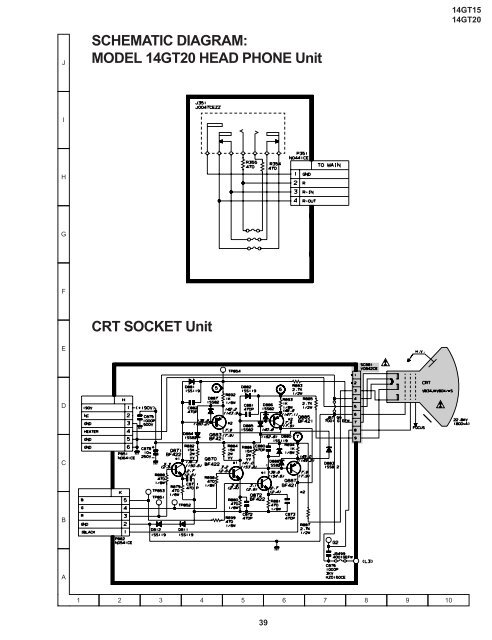
J SCHEMATIC DIAGRAM: MODEL 14GT20 HEAD PHONE Unit 14GT15 14GT20 I H G F E CRT SOCKET Unit D C B A 1 2 3 4 5 6 7 8 9 10 39
- Page 1 and 2: SERVICE MANUAL 14GT15 14GT20 S30Y11
- Page 3 and 4: 14GT15 14GT20 IMPORTANT SERVICE NOT
- Page 5 and 6: 14GT15 14GT20 SERVICE MODE (1) In t
- Page 7 and 8: 14GT15 14GT20 USER DATA IN SERVICE
- Page 9 and 10: 14GT15 14GT20 EEPROM ITEMS OSD DATA
- Page 11 and 12: PIF ADJUSTMENT 14GT15 14GT20 No. Ad
- Page 13 and 14: 14GT15 14GT20 CONVERGENCE ADJUSTMEN
- Page 15 and 16: HORIZONTAL AND VERTICAL DEFLECTION
- Page 17 and 18: FUNCTION OPERATION CHECKING (VIDEO
- Page 19 and 20: MEMORY MAP ADDRESS DATA MICON E 2 P
- Page 21 and 22: 14GT15 14GT20 ADDRESS DATA MICON E
- Page 23 and 24: 14GT15 14GT20 ADDRESS DATA MICON E
- Page 25 and 26: 14GT15 14GT20 ADDRESS DATA MICON E
- Page 27 and 28: TROUBLE SHOOTING TABLE 14GT15 14GT2
- Page 29 and 30: 14GT15 14GT20 TROUBLE SHOOTING TABL
- Page 31 and 32: SOLID STATE DEVICE BASE DIAGRAM 14G
- Page 33 and 34: 14GT15 14GT20 MODEL 14GT20 CHASSIS
- Page 35 and 36: DESCRIPTION OF SCHEMATIC DIAGRAM 14
- Page 37: J 14GT15 14GT20 C351 103B I H G R31
- Page 41 and 42: 14GT15 14GT20 J SCHEMATIC DIAGRAM:
- Page 43 and 44: 14GT15 14GT20 J BLOCK DIAGRAM - 2/3
- Page 45 and 46: J PRINTED WIRING BOARD ASSEMBLIES P
- Page 47 and 48: 14GT15 14GT20 14GT15 14GT20 PWB-A:
- Page 49 and 50: 14GT15 14GT20 Ref. No. Part No. Des
- Page 51 and 52: 14GT15 14GT20 Ref. No. Part No. Des
- Page 53 and 54: 14GT15 14GT20 Ref. No. Part No. Des
J<br />
SCHEMATIC DIAGRAM:<br />
MODEL <strong>14GT20</strong> HEAD PHONE Unit<br />
<strong>14GT15</strong><br />
<strong>14GT20</strong><br />
I<br />
H<br />
G<br />
F<br />
E<br />
CRT SOCKET Unit<br />
D<br />
C<br />
B<br />
A<br />
1 2 3 4 5 6 7 8 9 10<br />
39


