Mechanical APDL Basic Analysis Guide - Ansys
Mechanical APDL Basic Analysis Guide - Ansys
Mechanical APDL Basic Analysis Guide - Ansys
Create successful ePaper yourself
Turn your PDF publications into a flip-book with our unique Google optimized e-Paper software.
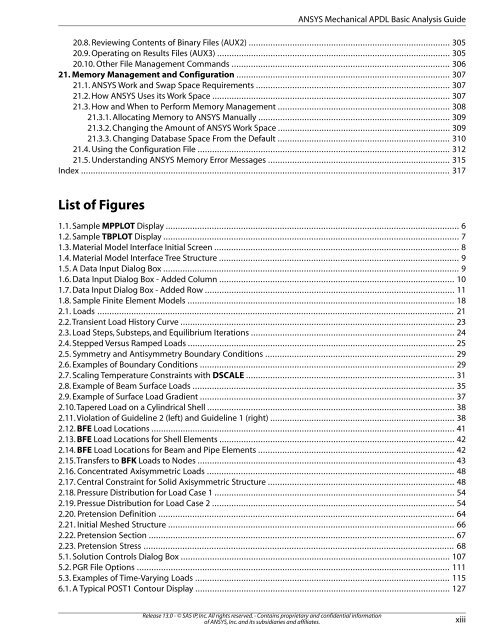
20.8. Reviewing Contents of Binary Files (AUX2) ................................................................................... 305<br />
20.9. Operating on Results Files (AUX3) ................................................................................................ 305<br />
20.10. Other File Management Commands .......................................................................................... 306<br />
21. Memory Management and Configuration ........................................................................................ 307<br />
21.1. ANSYS Work and Swap Space Requirements ................................................................................ 307<br />
21.2. How ANSYS Uses its Work Space .................................................................................................. 307<br />
21.3. How and When to Perform Memory Management ....................................................................... 308<br />
21.3.1. Allocating Memory to ANSYS Manually ............................................................................... 309<br />
21.3.2. Changing the Amount of ANSYS Work Space ....................................................................... 309<br />
21.3.3. Changing Database Space From the Default ....................................................................... 310<br />
21.4. Using the Configuration File ........................................................................................................ 312<br />
21.5. Understanding ANSYS Memory Error Messages ........................................................................... 315<br />
Index ........................................................................................................................................................ 317<br />
List of Figures<br />
1.1. Sample MPPLOT Display ......................................................................................................................... 6<br />
1.2. Sample TBPLOT Display .......................................................................................................................... 7<br />
1.3. Material Model Interface Initial Screen ..................................................................................................... 8<br />
1.4. Material Model Interface Tree Structure ................................................................................................... 9<br />
1.5. A Data Input Dialog Box .......................................................................................................................... 9<br />
1.6. Data Input Dialog Box - Added Column ................................................................................................. 10<br />
1.7. Data Input Dialog Box - Added Row ....................................................................................................... 11<br />
1.8. Sample Finite Element Models .............................................................................................................. 18<br />
2.1. Loads ................................................................................................................................................... 21<br />
2.2. Transient Load History Curve ................................................................................................................. 23<br />
2.3. Load Steps, Substeps, and Equilibrium Iterations .................................................................................... 24<br />
2.4. Stepped Versus Ramped Loads .............................................................................................................. 25<br />
2.5. Symmetry and Antisymmetry Boundary Conditions .............................................................................. 29<br />
2.6. Examples of Boundary Conditions ......................................................................................................... 29<br />
2.7. Scaling Temperature Constraints with DSCALE ...................................................................................... 31<br />
2.8. Example of Beam Surface Loads ............................................................................................................ 35<br />
2.9. Example of Surface Load Gradient ......................................................................................................... 37<br />
2.10.Tapered Load on a Cylindrical Shell ...................................................................................................... 38<br />
2.11. Violation of <strong>Guide</strong>line 2 (left) and <strong>Guide</strong>line 1 (right) ............................................................................ 38<br />
2.12. BFE Load Locations ............................................................................................................................. 41<br />
2.13. BFE Load Locations for Shell Elements ................................................................................................. 42<br />
2.14. BFE Load Locations for Beam and Pipe Elements ................................................................................. 42<br />
2.15.Transfers to BFK Loads to Nodes .......................................................................................................... 43<br />
2.16. Concentrated Axisymmetric Loads ...................................................................................................... 48<br />
2.17. Central Constraint for Solid Axisymmetric Structure ............................................................................. 48<br />
2.18. Pressure Distribution for Load Case 1 ................................................................................................... 54<br />
2.19. Pressue Distribution for Load Case 2 .................................................................................................... 54<br />
2.20. Pretension Definition .......................................................................................................................... 64<br />
2.21. Initial Meshed Structure ...................................................................................................................... 66<br />
2.22. Pretension Section .............................................................................................................................. 67<br />
2.23. Pretension Stress ................................................................................................................................ 68<br />
5.1. Solution Controls Dialog Box ............................................................................................................... 107<br />
5.2. PGR File Options ................................................................................................................................. 111<br />
5.3. Examples of Time-Varying Loads ......................................................................................................... 115<br />
6.1. A Typical POST1 Contour Display ......................................................................................................... 127<br />
Release 13.0 - © SAS IP, Inc. All rights reserved. - Contains proprietary and confidential information<br />
of ANSYS, Inc. and its subsidiaries and affiliates.<br />
ANSYS <strong>Mechanical</strong> <strong>APDL</strong> <strong>Basic</strong> <strong>Analysis</strong> <strong>Guide</strong><br />
xiii


