Commissioning the Air Barrier System - Air Barrier Association of ...
Commissioning the Air Barrier System - Air Barrier Association of ...
Commissioning the Air Barrier System - Air Barrier Association of ...

You also want an ePaper? Increase the reach of your titles
YUMPU automatically turns print PDFs into web optimized ePapers that Google loves.
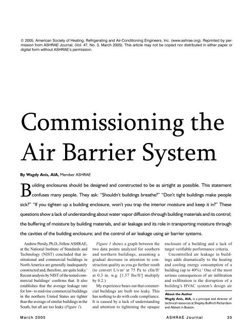
© 2005, American Society <strong>of</strong> Heating, Refrigerating and <strong>Air</strong>-Conditioning Engineers, Inc. (www.ashrae.org). Reprinted by permission<br />
from ASHRAE Journal, (Vol. 47, No. 3, March 2005). This article may not be copied nor distributed in ei<strong>the</strong>r paper or<br />
digital form without ASHRAE’s permission.<br />
<strong>Commissioning</strong> <strong>the</strong><br />
<strong>Air</strong> <strong>Barrier</strong> <strong>System</strong><br />
By Wagdy Anis, AIA, Member ASHRAE<br />
B<br />
uilding enclosures should be designed and constructed to be as airtight as possible. This statement<br />
confuses many people. They ask: “Shouldn’t buildings brea<strong>the</strong>?” “Don’t tight buildings make people<br />
sick?” “If you tighten up a building enclosure, won’t you trap <strong>the</strong> interior moisture and keep it in?” These<br />
questions show a lack <strong>of</strong> understanding about water vapor diffusion through building materials and its control;<br />
<strong>the</strong> buffering <strong>of</strong> moisture by building materials, and air leakage and its role in transporting moisture through<br />
<strong>the</strong> cavities <strong>of</strong> <strong>the</strong> building enclosure; and <strong>the</strong> control <strong>of</strong> air leakage using air barrier systems.<br />
Andrew Persily, Ph.D., Fellow ASHRAE,<br />
at <strong>the</strong> National Institute <strong>of</strong> Standards and<br />
Technology (NIST) concluded that institutional<br />
and commercial buildings in<br />
North America are generally inadequately<br />
constructed and, <strong>the</strong>refore, are quite leaky. 1<br />
Recent analysis by NIST <strong>of</strong> <strong>the</strong> tested commercial<br />
buildings 2 confirms that. It also<br />
establishes that <strong>the</strong> average leakage rate<br />
for low- to mid-rise commercial buildings<br />
in <strong>the</strong> nor<strong>the</strong>rn United States are tighter<br />
than <strong>the</strong> average <strong>of</strong> similar buildings in <strong>the</strong><br />
South, but all are too leaky (Figure 1).<br />
Figure 1 shows a graph between <strong>the</strong><br />
two data points analyzed for sou<strong>the</strong>rn<br />
and nor<strong>the</strong>rn buildings, assuming a<br />
gradual decrease in attention to construction<br />
quality as you go fur<strong>the</strong>r south<br />
(to convert L/s·m 2 at 75 Pa to cfm/ft 2<br />
at 0.3 in. w.g. [1.57 lbs/ft 2 ] multiply<br />
by 0.2.)<br />
My experience bears out that commercial<br />
buildings are built too leaky. This<br />
has nothing to do with code compliance.<br />
It is caused by a lack <strong>of</strong> understanding<br />
and attention to tightening <strong>the</strong> opaque<br />
enclosure <strong>of</strong> a building and a lack <strong>of</strong><br />
target verifiable performance criteria.<br />
Uncontrolled air leakage in buildings<br />
adds dramatically to <strong>the</strong> heating<br />
and cooling energy consumption <strong>of</strong> a<br />
building (up to 40%). 3 One <strong>of</strong> <strong>the</strong> most<br />
serious consequences <strong>of</strong> air infiltration<br />
and exfiltration is <strong>the</strong> disruption <strong>of</strong> a<br />
building’s HVAC system’s design air<br />
About <strong>the</strong> Author<br />
Wagdy Anis, AIA, is a principal and director <strong>of</strong><br />
technical resources at Shepley Bulfinch Richardson<br />
and Abbott in Boston.<br />
M a r c h 2 0 0 5 A S H R A E J o u r n a l 3 5
Laboratory mockup during an ASTM E283 air infiltration test, which tests assemblies <strong>of</strong> opaque walls, curtain walls and windows.<br />
pressure relationships. 4 This could prove catastrophic when<br />
lives depend on maintaining <strong>the</strong>se relationships, such as in<br />
hospital operating rooms, protected environment rooms, and<br />
infection control rooms. Or in o<strong>the</strong>r circumstances, pollutants<br />
can migrate from containment spaces to o<strong>the</strong>r spaces,<br />
and water vapor in <strong>the</strong> air can condense on colder surfaces<br />
within <strong>the</strong> enclosure assemblies to cause indoor air quality<br />
problems, mold growth, corrosion, rot and premature failure<br />
<strong>of</strong> <strong>the</strong> building enclosure.<br />
Prudent care during design and construction to commission<br />
<strong>the</strong> air barrier system is necessary to reasonably ensure that<br />
<strong>the</strong> design intent <strong>of</strong> <strong>the</strong> mechanical system can be achieved.<br />
For those concerned about lack <strong>of</strong> adequate ventilation if<br />
<strong>the</strong> enclosure is tight, <strong>the</strong>y should be aware that commercial<br />
buildings are required to be ventilated in accordance with<br />
ANSI/ASHRAE Standard 62.1, Ventilation for Indoor <strong>Air</strong><br />
Quality, which specifies sufficient outdoor ventilation air that<br />
is filtered, conditioned and delivered to <strong>the</strong> breathing zone to<br />
provide more than adequate outdoor air for breathing and for<br />
building pollutant dilution.<br />
<strong>Commissioning</strong> <strong>the</strong> <strong>Air</strong> <strong>Barrier</strong> <strong>System</strong><br />
The building enclosure should be designed and constructed<br />
tightly so <strong>the</strong> ventilation system can operate without disruption<br />
or loss <strong>of</strong> control (i.e., to promote durability and maintain comfort<br />
with good indoor air quality, acoustical isolation and energy<br />
conservation). To achieve this, an air barrier system needs to<br />
be designed and constructed into <strong>the</strong> building enclosure. The<br />
air barrier system should be:<br />
• Constructed <strong>of</strong> relatively air-impermeable materials and<br />
assemblies, interconnected with flexible joints;<br />
• Continuous throughout <strong>the</strong> enclosure;<br />
• Structurally supported to withstand positive and negative<br />
air pressures (including design wind pressures and gusts, as<br />
well as persistent low pressures such as stack effect and fan<br />
pressurization) without displacement and failure; and<br />
• Durable to last <strong>the</strong> life <strong>of</strong> <strong>the</strong> enclosure if inaccessible, or<br />
maintainable.<br />
<strong>Air</strong> barrier systems for a building enclosure are assembled<br />
from relatively air-impermeable materials (less than 0.004 cfm/<br />
ft 2 at 1.57 lbs/ft 2 [0.02 L/s·m 2 at 75 Pa]) interconnected to form<br />
3 6 A S H R A E J o u r n a l a s h r a e . o r g M a r c h 2 0 0 5
assemblies and <strong>the</strong> assemblies (such as opaque walls, windows,<br />
etc.) interconnected with flexible joints that can accommodate<br />
<strong>the</strong> expected relative movement <strong>of</strong> <strong>the</strong>se assemblies.<br />
All penetrations <strong>of</strong> <strong>the</strong> air barrier system are sealed. When<br />
such air-impermeable materials are assembled using sealants,<br />
tapes, gaskets, etc. and <strong>the</strong>n penetrated by screws, anchors,<br />
electrical outlets, etc., even though <strong>the</strong> connections and penetrations<br />
are carefully installed and sealed, <strong>the</strong> assembly becomes<br />
more leaky than <strong>the</strong> original<br />
basic air barrier material. Acceptable<br />
numbers for <strong>the</strong> air<br />
leakage <strong>of</strong> assemblies depend<br />
on what <strong>the</strong>y are made <strong>of</strong> and<br />
<strong>the</strong>ir tolerance to condensation<br />
moisture.<br />
The American Architectural<br />
Manufacturers <strong>Association</strong><br />
(AAMA) suggests a maximum<br />
<strong>of</strong> 0.06 cfm/ft 2 at 1.57 lbs/ft 2 ,<br />
(0.3 L/s·m 2 at 75 Pa), which<br />
may be suitable for glass and<br />
aluminum components. The<br />
appendix <strong>of</strong> <strong>the</strong> National Model<br />
Building Code <strong>of</strong> Canada<br />
recommends 0.02 cfm/ft 2 at<br />
1.57 lbs/ft 2 (0.1 L/s·m 2 at 75 Pa) as a maximum allowable leakage<br />
rate for building assemblies more vulnerable to moisture<br />
damage (and half <strong>of</strong> that for high humidity buildings).<br />
Again, if <strong>the</strong> drying potential <strong>of</strong> <strong>the</strong> assembly is low, <strong>the</strong>n <strong>the</strong><br />
tolerable leakage is less. This makes sense in all climates, even<br />
though <strong>the</strong> specific studies were done for cold climates. 5 It becomes<br />
more complicated if <strong>the</strong> air is infiltrating or exfiltrating,<br />
how much, <strong>the</strong> characteristics <strong>of</strong> <strong>the</strong> interior and exterior air,<br />
<strong>the</strong> size <strong>of</strong> <strong>the</strong> holes, <strong>the</strong> nature <strong>of</strong> <strong>the</strong> materials in <strong>the</strong> assembly,<br />
and <strong>the</strong> wea<strong>the</strong>r. Studies are ongoing at Oak Ridge National<br />
Labs, 6 <strong>the</strong> National Research Council Canada, and elsewhere<br />
in Europe. The air leakage rate <strong>of</strong> whole buildings per square<br />
foot <strong>of</strong> enclosure at <strong>the</strong> reference pressure <strong>of</strong> 75 Pa is a higher<br />
number than for assemblies by ano<strong>the</strong>r order <strong>of</strong> magnitude.<br />
The allowable air leakage for whole buildings has been described<br />
in ASHRAE Handbook—Fundamentals. Researchers<br />
Tamura and Shaw 7 in <strong>the</strong> 1980s measured and studied <strong>the</strong> air<br />
L/s · m 2 at 75 Pa<br />
14<br />
12<br />
10<br />
8<br />
6<br />
4<br />
2<br />
0<br />
<strong>Air</strong> Leakage Rate<br />
Target <strong>Air</strong> <strong>Barrier</strong> Building<br />
Tight Construction, Canada<br />
0 2,000 4,000 6,000 8,000 10,000<br />
Heating Degree Days HDD 65<br />
Figure 1: Buildings in <strong>the</strong> North are tighter than buildings in <strong>the</strong><br />
South; all are leaky.<br />
leakage <strong>of</strong> seven high-rise <strong>of</strong>fice buildings. They concluded that<br />
buildings are tight if <strong>the</strong>y achieve a normalized air leakage rate<br />
<strong>of</strong> <strong>the</strong> building enclosure not to exceed 0.1 cfm/ft 2 at 0.3 in. w.<br />
g. or 1.57 lbs/ft 2 (0.5 L/s·m 2 at 75 Pa) (see sidebar). 8<br />
Contemporary researchers such as Robert Dumont 9 have<br />
confirmed this number as a good maximum target for buildings,<br />
and it has been achieved and improved upon in projects that have<br />
been carefully monitored during design and inspected during<br />
construction. O<strong>the</strong>r evidence<br />
suggests this target may be<br />
difficult to achieve if you do<br />
not have an effective quality<br />
assurance/quality control program<br />
in place for <strong>the</strong> building<br />
enclosure during design and<br />
construction.<br />
A more readily achievable<br />
number with reasonable care<br />
in this author’s opinion is<br />
0.15 cfm/ft 2 at 0.3 in. w.g.<br />
In fact, 6% <strong>of</strong> all low-rise<br />
commercial buildings measured<br />
equal to or have lower<br />
air leakage rates than this<br />
number, without a special<br />
program in place for <strong>the</strong> enclosure. 10 It is likely that compliance<br />
with this number should be readily achievable with a<br />
target requirement in place.<br />
Doing it Right. The air barrier system needs to be identified<br />
by <strong>the</strong> architect in <strong>the</strong> construction documents on <strong>the</strong> building<br />
enclosure details, with a strong focus on intersections <strong>of</strong> different<br />
enclosure systems and transitions. You have to be able<br />
to trace through from one identified plane <strong>of</strong> airtightness in <strong>the</strong><br />
first assembly through a sealed joint to <strong>the</strong> plane <strong>of</strong> airtightness<br />
in <strong>the</strong> adjacent assembly. The specifications should have<br />
a special section on <strong>the</strong> air barrier system that includes all<br />
accessory materials.<br />
An ISO 9000 methodology in construction involves building<br />
quality into <strong>the</strong> process itself. The <strong>Air</strong> <strong>Barrier</strong> <strong>Association</strong> <strong>of</strong><br />
America’s 11 (ABAA) licensed contractors with trained and<br />
certified air-barrier technicians, follow a predefined quality<br />
assurance program (QAP) that includes documenting daily<br />
Calculating Normalized <strong>Air</strong> Leakage Rate<br />
Normalized <strong>Air</strong> Leakage Rate <strong>of</strong> <strong>the</strong> Building Enclosure: NLR75 =<br />
Q75/S, <strong>the</strong> average volume <strong>of</strong> air in cfm (L/s) that passes through a unit<br />
area <strong>of</strong> <strong>the</strong> building enclosure in ft 2 (m 2 ), expressed in cfm/ft 2 at 0.3<br />
in. w.g. (L/s·m 2 at 75 Pa), where Q75 is <strong>the</strong> volume <strong>of</strong> air in cubic feet<br />
per minute (L/s) flowing through <strong>the</strong> whole building enclosure when<br />
subjected to an indoor/outdoor pressure <strong>of</strong> 0.3 in. w.g. (1.57 lbs/ft 2 ) (75<br />
Pa) in accordance with ASTM E779; S, measured in ft 2 (m 2 ), is <strong>the</strong> total<br />
area <strong>of</strong> <strong>the</strong> enclosure air pressure boundary including any below-grade<br />
walls, slab, plus <strong>the</strong> gross area <strong>of</strong> suspended floors, above-grade walls<br />
and ro<strong>of</strong> (or ceiling), including windows and skylights, separating <strong>the</strong><br />
interior conditioned space from <strong>the</strong> unconditioned environment.<br />
Canadian researchers and investigators are reporting to this<br />
measurement unit. England is reporting to this unit too, although<br />
to a pressure <strong>of</strong> 50 Pa.<br />
M a r c h 2 0 0 5 A S H R A E J o u r n a l 3 7
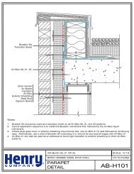
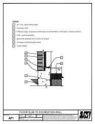
Alum. Fascia<br />
Continuous Cleat<br />
Lap & Seal Ro<strong>of</strong> Flashing Onto<br />
<strong>Air</strong> & Vapor <strong>Barrier</strong> Membrane<br />
Adhere With Ro<strong>of</strong>ing Adhesive<br />
Vents at 4 in. – 0 in. O.C.<br />
Exterior Plywood Typ.<br />
Pressure Treated Framing, Typ.<br />
Ro<strong>of</strong> Flashing<br />
Membrane Ro<strong>of</strong> <strong>Air</strong> <strong>Barrier</strong><br />
Cover Bd.<br />
18 Gauge Metal Angle<br />
Ship Lapped Deflection Joint<br />
<strong>Air</strong> & Vapor <strong>Barrier</strong> Membrane<br />
Rigid Insulation<br />
Vapor <strong>Barrier</strong><br />
Metal Deck<br />
Deflection Track<br />
Min. R-7 Rigid Insulation<br />
Veneer Anchor<br />
Steel Stud<br />
Gypsum Board<br />
Sheathing<br />
2 in. <strong>Air</strong> Cavity<br />
Face Brick<br />
5<br />
3 8 in. Varies 4 in. to 6 in.<br />
Figure 2: Continuity <strong>of</strong> <strong>the</strong> wall air/vapor barrier through a deflection joint with <strong>the</strong> ro<strong>of</strong> membrane used as <strong>the</strong> air barrier.<br />
progress and daily self-testing <strong>of</strong> <strong>the</strong> air barrier system. An<br />
ABAA auditor in a surprise visit(s), verifies that <strong>the</strong> QAP<br />
is followed and verifies <strong>the</strong> air barrier<br />
system’s installation quality. The subcontractor’s<br />
standing and certification may be<br />
affected by noncompliance.<br />
Was it Done Right? A third-party<br />
inspection and testing program may be<br />
instituted to peer review <strong>the</strong> design details<br />
and specifications, as well as to conduct prefunctional<br />
and functional air barrier system<br />
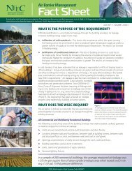
Figure 3: Infrared <strong>the</strong>rmography reveals<br />
hot spots that are usually air leaks.<br />
Figure 4: Chamber for pressurization/<br />
depressurization tests.<br />
inspection and testing. Inspection <strong>of</strong> <strong>the</strong> air<br />
barrier system would determine that:<br />
• Continuity <strong>of</strong> <strong>the</strong> air barrier system<br />
is clearly detailed on <strong>the</strong> drawings and is<br />
achieved throughout <strong>the</strong> building enclosure<br />
with no gaps or holes.<br />
• Continuous structural support <strong>of</strong> <strong>the</strong> air<br />
barrier system is provided.<br />
• Masonry and concrete substrate surfaces<br />
are flush, clean and free <strong>of</strong> cavities,<br />
protrusions and mortar droppings.<br />
• Site conditions for application temperature<br />
and dryness <strong>of</strong> substrates are observed.<br />
• Maximum length <strong>of</strong> exposure time <strong>of</strong> materials to ultraviolet<br />
deterioration is respected.<br />
• Surfaces are adequately primed prior to<br />
application <strong>of</strong> <strong>the</strong> air barrier membrane.<br />
• Laps in sheet materials meet <strong>the</strong> minimum<br />
requirements and are shingled in <strong>the</strong><br />
correct direction (and mastic applied to exposed<br />
and cut edges), with no fish-mouths.<br />
• A roller has been used to enhance<br />
adhesion.<br />
• Compatible materials have been used.<br />
• Transitions at changes in direction and<br />
structural support are provided at gaps.<br />
• Connections between assemblies (membrane<br />
and sealants) have been cleaned, and<br />
primed prior to sealant application;<br />
• The integrity and structural support <strong>of</strong><br />
connecting seals are satisfactory; and<br />
• All penetrations have been sealed.<br />
Testing Enclosure Components, Assemblies<br />
and Buildings for <strong>Air</strong> Leakage.<br />
Good practice on a project includes testing<br />
3 8 A S H R A E J o u r n a l a s h r a e . o r g M a r c h 2 0 0 5
L/s · m 2 cfm/ft 2<br />
5/16 in. Plywood 0.0067 0.0013<br />
5/8 in. Flakeboard 0.0069 0.0014<br />
1/2 in. Exterior Gypsum 0.0091 0.0018<br />
3/8 in. Flakeboard 0.0108 0.0021<br />
1/2 in. Particle Board 0.0155 0.0031<br />
Non-Perforated Spun Polyolefin 0.0195 0.0038<br />
1/2 in. Interior Gypsum Board 0.0196 0.0039<br />
CMHC List<br />
Smooth Surface Ro<strong>of</strong>ing Membrane, 2 mm<br />
Nonmeasurable<br />
Aluminum Foil Vapor <strong>Barrier</strong><br />
Nonmeasurable<br />
Modified Bituminous Torch-On Grade Membrane, 2.7 mm Glass Fibre Matt<br />
Nonmeasurable<br />
Modified Bituminous Self-Adhesive Membrane, 1.3 mm<br />
Nonmeasurable<br />
Modified Bituminous Torch-On Grade Membrane, 2.7 mm Polyester Reinforced Matt<br />
Nonmeasurable<br />
Plywood Sheathing, 9.5 mm<br />
Nonmeasurable<br />
Extruded Polystyrene, 38 mm<br />
Nonmeasurable<br />
Foil Back Urethane Insulation, 25.4 mm<br />
Nonmeasurable<br />
Cement Board, 12.7 mm<br />
Nonmeasurable<br />
Foil-Backed Gypsum Board, 12.7 mm<br />
Nonmeasurable<br />
Plywood Sheathing, 8 mm 0.0067 0.0013<br />
Flakewood Board, 16 mm 0.0069 0.0014<br />
Gypsum Board (M/R), 12.7 mm 0.0091 0.0018<br />
Flakewood Board, 11 mm 0.0108 0.0021<br />
Particleboard, 12.7 mm 0.0155 0.0031<br />
Reinforced Non-Perforated Polyolefin 0.0195 0.0038<br />
Gypsum Board, 12.7 mm 0.0196 0.0039<br />
Particleboard, 15.9 0.0260 0.0051<br />
AAC 0.0400 0.0079<br />
Tempered Hardboard, 3.2 mm 0.0274 0.0054<br />
Expanded Polystyrene, Type 2 0.1187 0.0234<br />
Ro<strong>of</strong>ing Felt, 30 lb 0.1873 0.0369<br />
Non-Perforated Asphalt Felt, 15 lb 0.3962 0.078<br />
Rigid Glass Fibre Insulation Board With Spun Bonded Olefin Film on One Face 0.4880 0.0961<br />
Plain Fibreboard, 11 mm 0.8223 0.1619<br />
Asphalt Impregnated Fibreboard, 11 mm 0.8285 0.1631<br />
Spun Bonded Olefin Film (1991 Product) 0.9593 0.1888<br />
Perforated Polyethylene, #1 4.0320 0.7937<br />
Perforated Polyethylene, #2 3.2307 0.636<br />
Expanded Polystyrene, Type 1 12.2372 2.4089<br />
Tongue and Groove Planks 19.1165 3.7631<br />
Glasswool Insulation 36.7327 7.2308<br />
Vermiculite Insulation 70.4926 13.8765<br />
Cellulose Insulation, Spray-On 86.9457 17.1153<br />
Table 1: <strong>Air</strong> leakage rate for average North American buildings.<br />
component, assembly and even <strong>the</strong> whole building for air infiltration.<br />
It is good verification that it was done right. Although,<br />
if you wait until <strong>the</strong> building is complete to find out if <strong>the</strong><br />
building has been adequately sealed, <strong>the</strong>n it’s probably too late,<br />
and may become an expensive proposition<br />
to retroactively seal <strong>the</strong> building. It would<br />
be possible only to seal <strong>the</strong> big holes, not<br />
<strong>the</strong> smaller systemic ones. That’s not what<br />
commissioning is about!<br />
Two categories <strong>of</strong> testing are:<br />
1. Laboratory testing <strong>of</strong> assemblies and<br />
mock-ups, and<br />
2. Field-testing <strong>of</strong> assemblies and <strong>the</strong><br />
Laboratory Testing<br />
Window and door products must be tested and certified in<br />
accordance with <strong>the</strong> National Fenestration Rating Council’s<br />
(NFRC) test protocols, such as NFRC 500, ASTM E283 or<br />
E 330. Garage doors are tested according to ANSI/DASMA<br />
105 to comply with code. Reasonable<br />
air leakage rates for glazed products and<br />
doors are required by codes and standards<br />
as well as recommended by organizations<br />
such as AAMA.<br />
The maximum air permeance <strong>of</strong> air<br />
barrier materials is not, as <strong>of</strong> this writing,<br />
regulated by <strong>the</strong> model codes in<br />
actual building.<br />
Figure 5: The “bubble gun.”<br />
<strong>the</strong> United States. However, air barrier<br />
M a r c h 2 0 0 5 A S H R A E J o u r n a l 3 9
materials should be tested and qualified per ASTM E2178 not<br />
to exceed 0.004 cfm at 0.3 in. w.g. or 1.57 lbs/ft 2 (0.02 L/s·m 2<br />
at 75 Pa). 12<br />
Table 1 shows <strong>the</strong> materials tested by Canada Mortgage and<br />
Housing Corporation and <strong>the</strong>ir air leakage rates at 0.3 in. w.g.<br />
(75 Pa).<br />
Assemblies <strong>of</strong> opaque walls, curtain walls and windows can<br />
be tested in <strong>the</strong> lab in accordance with NFRC 400 or ASTM<br />
E 283 (air infiltration), ASTM E 331 (water penetration under<br />
static pressure), AAMA test procedure 501.1 (water penetration<br />
under dynamic pressure) ASTM<br />
E 330 (structural adequacy), NFRC<br />
500 or AAMA 1502.7 (condensation<br />
resistance factor or CRF), NFRC 100<br />
or AAMA 1503.1 (<strong>the</strong>rmal transmittance),<br />
NFRC 200 (solar heat gain<br />
coefficient), NFRC 300 (solar optical<br />
properties <strong>of</strong> glazing products).<br />
Ano<strong>the</strong>r test for air barrier assemblies<br />
is ASTM E1677; it is a test for<br />
low-rise residential buildings and<br />
includes an 8 ft by 8 ft (2.4 × 2.4 m)<br />
panel that has panel joints, a blanked<strong>of</strong>f<br />
window, a duct penetration, an<br />
electric outlet, etc. The maximum test<br />
pressure suggested in this test may<br />
be too low to simulate wind loads for<br />
most building locations and for taller<br />
buildings, so a test pressure more<br />
representative <strong>of</strong> design wind and<br />
gust pressures at <strong>the</strong> project site (plus<br />
a safety factor) should be required<br />
by <strong>the</strong> A/E. Infiltration is reported<br />
with this test as cfm/ft 2 at 0.3 in. w.g.<br />
(L/s·m 2 at 75 Pa).<br />
The Canadian Centre for Materials in Construction has established<br />
an elaborate test protocol for air barrier assemblies<br />
that includes three test panels. The <strong>Air</strong> <strong>Barrier</strong> <strong>Association</strong> <strong>of</strong><br />
America is bringing a similar test to ASTM and is planning<br />
within ASTM a whole family <strong>of</strong> test methods, specifications<br />
and standards for materials, assemblies and components (sealants<br />
and joint materials).<br />
Figure 6: Cutting around <strong>the</strong> disk.<br />
Figure 7: Pulling material to failure.<br />
Field Testing<br />
ASTM E 1186 contains several useful qualitative tests to chase<br />
down leaks. Infrared scanning with pressurization/depressurization<br />
is useful in determining leaks in <strong>the</strong> winter or summer. In <strong>the</strong><br />
winter, leaking warm air heats up <strong>the</strong> enclosure and shows up as<br />
a bright spot in <strong>the</strong> picture (Figure 3) (this also can be caused by<br />
a <strong>the</strong>rmal bridge, which can be identified from <strong>the</strong> design details<br />
or insulation inadequacies during construction).<br />
The reverse happens in <strong>the</strong> summer with air conditioning<br />
indoors. The dark spots are spots cooled by exiting cool air, or<br />
o<strong>the</strong>r enclosure problems.<br />
Several o<strong>the</strong>r tests within E1186 are rarely used, but two are<br />
worthy <strong>of</strong> note. Chamber pressurization/depressurization in conjunction<br />
with smoke tracers is a useful test to determine <strong>the</strong> location<br />
<strong>of</strong> air leaks in connections between building components such<br />
as windows and skylights with <strong>the</strong>ir adjacent constructions.<br />
A chamber is created using polyethylene and a simple wood<br />
frame (Figure 4), a smoke device is released, or generated<br />
using <strong>the</strong>atrical foggers, while air from a fan depressurizes or<br />
pressurizes depending on <strong>the</strong> configuration.<br />
Chamber depressurization<br />
using detection liquids uses a device<br />
nicknamed <strong>the</strong> “bubble gun” (Figure<br />
5). A bubble solution is spread on <strong>the</strong><br />
suspected penetration or joint, such<br />
as a brick tie fastened to a wall. The<br />
plastic dome <strong>of</strong> <strong>the</strong> device is placed<br />
over <strong>the</strong> area and depressurized to<br />
500 Pa (2 in. w.g.). Bubbles form if<br />
an air leak exists.<br />
The bond <strong>of</strong> <strong>the</strong> air barrier to its<br />
substrate is important because <strong>of</strong><br />
<strong>the</strong> requirement <strong>of</strong> <strong>the</strong> membrane<br />
to transfer <strong>the</strong> design wind negative<br />
loads to <strong>the</strong> substrate. Manufacturers<br />
<strong>of</strong> most air barrier products that are<br />
ei<strong>the</strong>r peel-and-stick or liquid-applied<br />
publish data on quality <strong>of</strong> adhesion to<br />
substrates. Testing using a pull-meter<br />
can be done by following ASTM<br />
D4541. A disk is epoxied to <strong>the</strong> material<br />
to be tested, and <strong>the</strong> material is cut<br />
around <strong>the</strong> disk (Figure 6). Tightening<br />
<strong>the</strong> device pulls <strong>the</strong> material to failure<br />
(Figure 7), and <strong>the</strong> test pressure is recorded and compared to <strong>the</strong><br />
manufacturer’s specifications. A 12 psi (83 kPa) minimum bond<br />
should be satisfactory for long-term durability. Note that patching<br />
<strong>of</strong> <strong>the</strong> test area will be necessary.<br />
The adhesion quality <strong>of</strong> air barrier membranes can be affected<br />
by <strong>the</strong> wetness <strong>of</strong> <strong>the</strong> substrate before application or by<br />
low application temperatures.<br />
ASTM E783 is a test for air infiltration <strong>of</strong> wall or window<br />
assemblies. ASTM E1105 is a spray rack water infiltration<br />
testing <strong>of</strong> wall or window assemblies, using <strong>the</strong> same pressurization/depressurization<br />
equipment as E783 and is usually run<br />
at <strong>the</strong> same time as E783.<br />
Whole Building Testing<br />
Testing whole commercial buildings usually is done for U.S.<br />
research, although it is more common in Canada. It has become<br />
a requirement for building acceptance in England and Wales<br />
4 0 A S H R A E J o u r n a l a s h r a e . o r g M a r c h 2 0 0 5
since 2002. It is likely that as <strong>the</strong> importance <strong>of</strong> airtightness <strong>of</strong><br />
<strong>the</strong> building enclosure becomes more appreciated or regulated,<br />
whole building testing will become more prevalent in North<br />
America. The cost <strong>of</strong> testing a commercial building can vary<br />
from $1,000 to $15,000 depending on complexity and size.<br />
Tests include:<br />
• Whole building, floors, or suites, ASTM E 779, Determining<br />
<strong>Air</strong>tightness <strong>of</strong> a Building’s <strong>Air</strong> Leakage Rate by Single<br />
Zone <strong>Air</strong> Pressurization.<br />
• CAN/CGSB 1986 Standard 149.10, Determination <strong>of</strong> <strong>the</strong><br />
<strong>Air</strong>tightness <strong>of</strong> Building Enclosures by <strong>the</strong> Fan Depressurization<br />
Method; and<br />
• CAN/CGSB 1996 Standard 149.15, Determination <strong>of</strong> <strong>the</strong><br />
Overall Enclosure <strong>Air</strong>tightness <strong>of</strong> Office<br />
Buildings by <strong>the</strong> Fan Depressurization<br />
Method Using <strong>the</strong> Building’s<br />
<strong>Air</strong> Handling <strong>System</strong>.<br />
Trailer-mounted fans (with large<br />
blower doors) for testing large buildings,<br />
delivering up to 55,000 cfm at<br />
75 Pa (26 000 L/s at 0.3 in. w.g.) or<br />
larger are available from a U.S. source.<br />
Several <strong>of</strong> <strong>the</strong>se may be required to<br />
test a large, leaky, building, although<br />
inaccuracies are introduced with<br />
<strong>the</strong> use <strong>of</strong> multiple fans. In testing a<br />
whole building, all <strong>the</strong> “intentional<br />
holes” such as ventilation air intakes,<br />
exhaust fan outlets and louvers, elevator shaft smoke exhaust,<br />
flues, etc., have to be sealed, usually with polyethylene and<br />
tape. Low wind conditions, lower than 8.5 mph (14 km/h) and<br />
only a small temperature differential between indoor and out<br />
(outdoor temperature between 40°F and 95°F [5°C and 35°C])<br />
helps reduce <strong>the</strong> influence <strong>of</strong> wind and stack effects.<br />
Interior doors need to be open so <strong>the</strong> building is turned into<br />
a single zone. The volume <strong>of</strong> air being moved is recorded at <strong>the</strong><br />
pressure differential; this is done for several different pressures<br />
in steps <strong>of</strong> 12.5 Pa to 75 Pa (0.05 to 0.3 in. w.g.). If <strong>the</strong> building<br />
is too large to test with a single fan, multiple fans can be used,<br />
or <strong>the</strong> building’s air handlers can be used instead; <strong>the</strong> fans need<br />
to be evaluated for cfm output; <strong>the</strong> test can <strong>the</strong>n proceed and<br />
<strong>the</strong> fans progressively turned on to pressurize <strong>the</strong> building with<br />
pressure measurements taken at each step.<br />
The flow coefficient C and <strong>the</strong> flow exponent n are evaluated<br />
using <strong>the</strong> power law equation:<br />
Where<br />
Q75 = C (∆P) n<br />
Q75 is <strong>the</strong> quantity <strong>of</strong> air leakage (cfm [L/s]) at<br />
0.3 in. (75 Pa)<br />
C is <strong>the</strong> flow coefficient (C = flow coefficient,<br />
cfm/(in. <strong>of</strong> water) n (L/s/(Pa) n<br />
∆P is <strong>the</strong> pressure differential between indoors<br />
and outdoors (in. water, [Pa])<br />
n = pressure exponent, dimensionless.<br />
The Normalized <strong>Air</strong> Leakage Rate for <strong>the</strong> Building Enclosure<br />
is <strong>the</strong>n calculated using <strong>the</strong> method outlined in <strong>the</strong> sidebar<br />
Conclusion<br />
<strong>Commissioning</strong> <strong>the</strong> air barrier system is important in <strong>the</strong> design<br />
and construction <strong>of</strong> buildings that are sustainable, healthful,<br />
durable, and energy efficient. For high-security buildings, unless<br />
<strong>the</strong>ir building enclosure is designed and constructed as tightly<br />
as possible, and <strong>the</strong> air barrier system commissioned, it would<br />
be impossible to pressurize <strong>the</strong> building adequately to reduce<br />
<strong>the</strong> likelihood <strong>of</strong> infiltration, <strong>the</strong>reby potentially compromising<br />
<strong>the</strong> interior environment to chemical,<br />
biological or radiological agents. 13 An<br />
adequate budget needs to be assigned<br />
early in <strong>the</strong> project process to fund<br />
<strong>the</strong> commissioning activities needed<br />
to ensure a successful outcome that<br />
meets <strong>the</strong> owner’s project expectations<br />
for a tight building enclosure.<br />
References and Notes<br />
1. Persily, A. “Blowing Holes in <strong>the</strong><br />
Myth <strong>of</strong> <strong>Air</strong> Tightness <strong>of</strong> Institutional<br />
Figure 8: Testing a window enclosure and its perimeter<br />
joint using ASTM E 283.<br />
and Commercial Buildings.” Whole<br />
Buildings VII.<br />
2. 2005. Emmerich, S.J., NIST.<br />
3. Pollock. 2001. BETEC/DOE/ORNL Spring Symposium: <strong>Air</strong><br />
<strong>Barrier</strong> Solutions.<br />
4. Anis. W. 2001. “The impact <strong>of</strong> airtightness on system design.”<br />
ASHRAE Journal 43(12).<br />
5. Ojanen, T. and K. Kumaran. “Effect <strong>of</strong> exfiltration on <strong>the</strong> hygro<strong>the</strong>rmal<br />
behaviour <strong>of</strong> a residential wall assembly.” Results From<br />
Calculations and Computer Simulations. Canadian Construction<br />
Materials Centre (CCMC) Technical Guide.<br />
6. Karagiozes, A.N. “Impact <strong>of</strong> air leakage on <strong>the</strong> <strong>the</strong>rmal and<br />
moisture performance <strong>of</strong> <strong>the</strong> building envelope.” ORNL.<br />
7. Institute for Research in Construction, National Research Council<br />
<strong>of</strong> Canada.<br />
8. 2001 ASHRAE Handbook—Fundamentals, Chapter 26.24.<br />
9. Saskatchewan Research Council.<br />
10. As analyzed by Emmerich, S.J. 2004. Building Fire Research<br />
Laboratory, NIST.<br />
11. www.airbarrier.org.<br />
12. As qualified by <strong>the</strong> <strong>Air</strong> <strong>Barrier</strong> <strong>Association</strong> <strong>of</strong> America, <strong>the</strong><br />
ASHRAE HOF, ASHRAE’s Advanced Office Building Design Guidelines,<br />
<strong>the</strong> New Buildings Institute’s Advanced Building Guidelines,<br />
<strong>the</strong> Commonwealth <strong>of</strong> Massachusetts Building Code, and The Model<br />
National Building Code <strong>of</strong> Canada.<br />
13. Persily, A. 2004. “Building ventilation and pressurization as a<br />
security tool.” ASHRAE Journal 11(46).<br />
M a r c h 2 0 0 5 A S H R A E J o u r n a l 4 1