GO-KART SET UP INSTRUCTIONS FOR: Model ... - Family Go Karts
GO-KART SET UP INSTRUCTIONS FOR: Model ... - Family Go Karts
GO-KART SET UP INSTRUCTIONS FOR: Model ... - Family Go Karts

You also want an ePaper? Increase the reach of your titles
YUMPU automatically turns print PDFs into web optimized ePapers that Google loves.
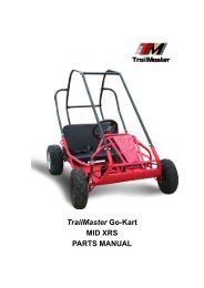
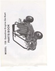
<strong>GO</strong>-<strong>KART</strong> <strong>SET</strong> <strong>UP</strong> <strong>INSTRUCTIONS</strong> <strong>FOR</strong>:<br />
<strong>Model</strong> # 2575, 2585<br />
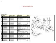
Parts for assembly:<br />
A-5/16”x2”(4) B-5/16”x1.75”(7) C-5/16”x1.5”(2) D-5/16” washer(10)<br />
E-5/16” lock nut(12) F-5/16” flange nut(1) G-1/4”x3/4”(3) H-1/4” lock washer(3)<br />
I-1/4”nut(3) J-3/4” acorn nut(2) K-3/4” washer(2) L-steering wheel(1)<br />
M-frame bar(2) N-engine bar(1) O-cross bar(1) P-U-bar(1)<br />
Q-flag(1) R-flag bracket(1) S-foam padding(2) T-foam cover(2)<br />
U-seat(1) V-seat cover(1) W-battery(1) X-battery cushion(1)
Y-battery strap(1)<br />
Z-battery cap(1)<br />
Step 1: Seat<br />
Tools needed: ½” wrench and socket<br />
Parts needed: C(2), E(2), U(1), V(1)<br />
Place seat (U) in floor board of kart. Align holes in side of seat with slots in side of frame<br />
according to where you want the seat. Insert bolt C in each side of seat and use nut E to tighten with a ½”<br />
wrench and socket.<br />
Step 2: Steering wheel<br />
Tools needed: 7/16” wrench<br />
Parts needed: G(3), H(3), I(3), L(1)<br />
Align holes of steering wheel (L) with holes in steering column. Using G, H, and I tighten steering<br />
wheel to steering column using a 7/16” wrench.<br />
Step 3: CBC<br />
Tools needed: ½” wrench and socket<br />
Parts needed: A(3), B(7), D(10), E(10), M(2), N(1), O(1), P(1),<br />
Place U-bar (P) over the 1” tubing behind the seat. The brake rod is bent so that the U-bar can<br />
connect to the frame without interfering with it. Place one of each of the following in each end of the U-bar<br />
and finger tighten only; A, D, and E.
Take engine bar (N) and place in the center of the rear bumper between the two welds. Place one<br />
of each in the bottom of the engine bar and finger tighten only; A, D, and E. The top of the engine bar will<br />
over lap the center of the U-bar. Align the center hole of the U-bar with the top of the engine bar and finger<br />
tighten using one of each of the following; B, D, and E.<br />
Connect the top of each frame bar (M) to the outermost holes in the U-bar and finger tighten only<br />
using the following; B, D, and E. Bent portion of the frame bar is the top.<br />
Pull the front of each frame bar over the front bumper and align holes. Finger tighten only using<br />
the following; B, D, and E.<br />
Place cross bar (O) over each frame bar and align holes. Finger tighten only using the following;<br />
B, D, and E. With all CBC members in place tighten all bolts with a ½” wrench and socket.<br />
Place foam padding (S) over top of each frame bar and cover with foam cover (T).
Step 4: Seat belts<br />
Tools needed: ¾” wrench<br />
Parts needed: J(2), K(2)<br />
Take open end of each seat belt and attach to U-bar using J and K. Tighten with ¾” wrench.<br />
Step 5: Flag<br />
Tools needed: ½” wrench and socket<br />
Parts needed: A(1), F(1), Q(1), R(1)<br />
Take the flag bracket (R) and connect flag (Q) to rear bumper using A and F.<br />
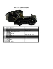
Step 6: Battery<br />
Tools needed: Phillips head screw driver<br />
Parts needed: W(1), X(1), Y(1), Z(1)<br />
Remove the battery cushion (X) backing and stick in bottom of battery box. Place battery (W) in<br />
battery box. Connect ground cable to “ -“ post and starter solenoid cable to “+” post of battery. Place battery<br />
cap (Z) over the battery and strap down with battery strap (Y).<br />
12/02/08