Racer Gauge 60&52mm gauges - Defi
Racer Gauge 60&52mm gauges - Defi
Racer Gauge 60&52mm gauges - Defi

You also want an ePaper? Increase the reach of your titles
YUMPU automatically turns print PDFs into web optimized ePapers that Google loves.
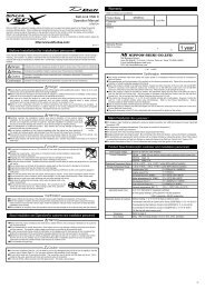
Manual<br />
<br />
SI & Imperial Series<br />
<br />
<br />
<br />
Thank you very much for purchasing our product.<br />
This product is an additional product for providing information to automobile users about engine conditions<br />
and other important factors. Before installing and using the product, please read this manual and the<br />
warranty card thoroughly. All sections are for customers and installation personnels. After installation,<br />
please keep this manual and the warranty card for future reference. In the event that this product (or the<br />
vehicle in which it is installed) is lent to or transferred to another person, please be sure this operation<br />
manual and warranty card accompany the product.<br />
<strong>Defi</strong> will not be held responsible for accidents or damages related to installation of this product.<br />
When installing and operating this product, be sure to read the cautionary items in the operation manual for<br />
the vehicle in which this product will be installed in addition to the manual of this product. Please obtain a<br />
full understanding of the cautionary items and use the product accordingly. Before using the product,<br />
please confirm all the components are included in the package.<br />
Safety WarningPlease read carefully.<br />
In this manual, the degree of hazard arising from actions such as improper operation is separated into the 3<br />
levels "Danger," "Warning," and "Caution." In addition, instructions that must be followed for safe and<br />
proper use of this product as well as practices that must be maintained are marked with a "Confirmation"<br />
heading. Please read and become familiar with these sections.<br />
Danger<br />
Warning<br />
Caution<br />
Confirmation<br />
<br />
Prohibited<br />
Must<br />
http://www.defi-shop.com/<br />
Indicates the imminent dangerous situation of death or serious injury if the product is<br />
mishandled.<br />
Indicates the possibility of death or serious injury if the product is mishandled.<br />
Indicates a conceivable source of personal injury or damage to equipment if the product<br />
is improperly operated.<br />
Indicates an instruction that must be performed or practice that must be maintained.<br />
Before handling (for installation personnel)<br />
Indicates attention needs to be paid. (Including warnings)<br />
Indicates restricted actions. (PROHIBITED actions)<br />
Indicates actions that need to be carried out. (MUST actions)<br />
Danger<br />
Ensure that the vehicle will remain stationary and turn off the engine before installing this product. Failure to do so<br />
could result in a fire, and could make the vehicle move during installation.<br />
Remove the key from the ignition and disconnect the negative (-) battery terminal prior to installation of this product.<br />
Failure to do so could result in a fire caused by an electrical short circuit.<br />
Take care not to install this product in a way that interferes with safety equipment such as seat belts and air bag<br />
systems or vehicle operation equipment such as engine controls, steering wheel or brake systems. Interference<br />
with normal operation of the vehicle can result in an accident or fire.<br />
Solder or use a solderless connector for wiring connections and make sure connections are insulated. In areas<br />
where there could be tension or sudden impacts on the wiring, safeguard the wiring with corrugated tubing or other<br />
shock absorbent material. Accidental shorts can cause fires.<br />
When wiring power supply wire, to avoid the risk of electrical shock or fire, be sure to confirm that there is no<br />
disconnection or breakage of wire. Poor connection can result in short-circuit, electrical shock, fire, or other hazards.<br />
Discontinue use of this product if a blowout of the fuse has occurred. Continued use while the condition exists could<br />
result in an accident, fire, or damage to the vehicle.<br />
Use the fuse of regulated capacity when the fuse of the power wire is changed. Using a fuse that exceeds regulated<br />
capacity may cause fire and may affect the accuracy.<br />
Do not install the product at the wet places. It may result in a fire caused by an electrical short circuit.<br />
Warning<br />
Carefully consider the installation location and driver's operation of the product before installation. Do<br />
not install the product where it interrupts driving and the safety deices of vehicle such as the airbag<br />
system. Be sure not to install the unit where it could fall. Improper installation or operation could<br />
cause the product to fall and damage the vehicle or cause serious danger by impeding driving.<br />
Do not disassemble or modify this product. Such actions will not only void the warranty but also<br />
damage or destroy the product.<br />
Do not perform installation of this product immediately after the engine has been switched off. The<br />
engine and exhaust system are extremely hot at this time and can cause burns if touched.<br />
Caution<br />
'12.07-2<br />
IMPORTANT<br />
disassemble/<br />
modify<br />
Ensure that the wiring of this product does not have an adverse impact on the other wiring of the vehicle. Any<br />
controlling devices or other electronic components of the vehicle could be damaged.<br />
Discontinue use of this product if the product doesn't operate or operates improperly. Continued use while the<br />
condition exists could result in an accident or fire.<br />
Please keep children and infants away from the installation area. Children may swallow small parts or be injured in other ways.<br />
Do not install this product in the area where safety equipment such as airbags are mounted. This may cause more<br />
injuries in the event of an accident.<br />
This product is designed for use on 12V vehicles. Do not install this product on vehicles with 24V systems.<br />
Insulate any unused wires. If any wires or connectors loosen during installation, please make sure<br />
they are correctly reattached.<br />
Do not drop any of the components of this product. It may result in damage to the product.<br />
Do not apply excessive force on switches/terminals. It may result in damage to the product.<br />
Do not use wires other than the provided wires.<br />
24V<br />
Do not attach wires on the body of the vehicle or engine parts as this may result in damage to the product.<br />
Install wires away from ignition and also radio signal frequency interference as this could cause the <strong>gauges</strong> to malfunction.<br />
Do not place wires near the engine, exhaust pipe or turbine. It may result in damage or fusion of wires.<br />
Make sure the waterproof processing is done when diverging wires in the engine compartment.<br />
When installing the sensor, do not bend the wire near the sensor body.<br />
Wear gloves to avoid burns when soldering and cuts when installing wires, sharp edges of parts.<br />
Install sensors away from hot or wet places.<br />
When using sunshade, put sunshade between products and windshield to avoid direct sun exposure .<br />
Use the dried soft cloth for cleanup. Do not use the cleaner except for the neutral detergent. It result in the trouble.<br />
Do not share single fuse with multiple <strong>gauges</strong>. Every gauge requires independent fuse for IGN and +B line.<br />
Do not pull the wires out of connectors forcefully. The connectors may be broken and the<br />
wires may be cut. When pulling out the wires, press the lock firmly and unclip the locks of<br />
connectors.<br />
Do not install <strong>gauges</strong> into the passenger side or center of the dashboard. It doesn't meet<br />
vehicle safety standards.<br />
Confirmation<br />
Be sure to follow all instructions in this manual to ensure safe installation and operation of the product.<br />
When the negative (-) battery terminal is disconnected, equipment such as clocks and audio components having<br />
internal memory may lose their memory data. Follow the operation manual of each component to reset data after<br />
installation of this product.<br />
Do not lay the gauge face down due to oil leakage. Angle "A" must be more than 90 degrees.<br />
After installation is complete, return this operation manual, warranty card, and the package to<br />
the customer along with the warranty.<br />
The gauge pointer may not be in the proper position when you purchase the product. Normal<br />
function will resume when power is connected.<br />
WEAR<br />
SAFETY GLASSES<br />
<br />
<br />
Please confirm with the maintenance book on the car that the manufacturer issued when installing and detaching<br />
genuine parts.<br />
Before tapping wires, check the voltage of the existing wire. After tapping the wire, check the voltage of the tapped<br />
wire again to confirm whether you have tapped into the proper place.<br />
If car navigation system or car television is installed in vehicle, <strong>gauges</strong> and wires of this product need to be kept as<br />
far away as possible from the wiring and installing positions of car navigation system or car television. Failure to do<br />
so may result in interference of television display.<br />
On no event will Nippon Seiki Co., Ltd. be liable to you for any damages or losses of genuine parts for your vehicle<br />
while installing.<br />
About Installation and Operation(for customer and installation personnel)<br />
Warning<br />
Please have this product installed by the retail store or dealer where it was purchased. Installation by the customer<br />
will void the warranty.<br />
Do not disassemble or modify this product. Such actions will not only void the warranty but also damage or destroy the product.<br />
In order to ensure safe driving, check the information on the gauge only for short periods of time. Looking at the<br />
display for long periods of time could distract adequate attention from the road and result in an accident.<br />
Discontinue use of this product if the gauge doesn't operate, water gets into the unit, or smoke or a strange odor<br />
comes from the unit. If such a condition occurs, contact the sales outlet or installation personnel as soon as<br />
possible. Continued use while the condition exists could result in an accident or fire.<br />
Do not operate during driving.<br />
Fix the switch unit and other parts tightly to the vehicle to avoid that children swallow those.<br />
Caution<br />
On no event will Nippon Seiki Co., Ltd. be liable to you for any damages arising out of the use or inability to use the<br />
product, even if Nippon Seiki Co., Ltd. has been advised of the possibility of such damage.<br />
Do not pull the wires out of connectors forcefully. The connectors may be broken and<br />
the wires may be cut. When pulling out the wires, press the lock firmly and unclip the<br />
locks of connectors.<br />
Confirmation<br />
This product cannot be linked to either the ADVANCE System or the <strong>Defi</strong>-Link System.<br />
The information displayed on this product are for reference purposes only. Please drive according to the indication<br />
of vehicle's originally equipped instruments.<br />
This product uses high luminance LEDs. When several <strong>gauges</strong> are lined up, there might be color difference in the<br />
LED production tolerance, but it is not malfunction.<br />
Please check the installed product regularly. Durability might deteriorate according to use conditions, etc.<br />
Lineup (for customer)<br />
SI models<br />
Illumination color Blue Red White<br />
Size(mm) <br />
TURBO<br />
PRESS.<br />
TEMP.<br />
EXT.T.<br />
VOLT<br />
<br />
<br />
<br />
<br />
<br />
<br />
<br />
<br />
<br />
<br />
<br />
<br />
<br />
<br />
<br />
<br />
<br />
<br />
<br />
<br />
<br />
<br />
<br />
<br />
<br />
<br />
<br />
<br />
<br />
<br />
Imperial models<br />
Illumination color Blue Red White<br />
Size(mm) <br />
BOOST DF06501 DF06502 DF06503 <br />
PRESS. DF06601 DF06602 DF06603 <br />
TEMP. DF06701 DF06702 DF06703 <br />
E.G.T. DF06801 DF06802 DF06803 <br />
VOLT DF07004 DF07005 DF07006 <br />
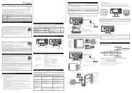
Main Features (for customer)<br />
Stepping motor "STEP MASTER VS-2" provides smooth operation.<br />
Ignition ON initiates self-luminescence gauge.<br />
Illumination using high-brightness LEDs<br />
Lightning-like Opening / Closing mode<br />
Self-diagnostics function monitors both sensor disconnection and short-circuiting during startup.<br />
a) Sensor disconnection check<br />
This function reports any in-proper connections, broken or disconnected sensor or sensor<br />
wire. The pointer will wave between 250 and 260 degrees.<br />
b) Short-circuiting check<br />
This function indicates any short circuit on the sensor or sensor wire.<br />
The pointer will wave between 10 and 20 degrees.<br />
Full 270sweep dial provides ultimate visibility.<br />
A mounting bracket and instrument case is provided with the product.<br />
The red triangle of the regular position bezel can be used as a warning indicator and others.<br />
Product Specificationsfor customer and installation personnel<br />
Power-supply voltage: 10V to 15V DC (12V vehicles only)<br />
Current consumption: +B line: MAX 120mA (Dark current 0mA)<br />
IGN line: MAX 120mA<br />
ILM line: MAX 2mA<br />
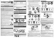
Installation or customer and installation personnel<br />
How to wire the power supply wire<br />
1) Disconnect negative ( - ) battery cable.<br />
2) Connect the power supply wire as shown below.<br />
3) Connect each sensor. Refer to "How to attach sensor" sections. (Except the Volt gauge)<br />
4) Connect the sensor wire.<br />
5) Reconnect negative ( - ) battery cable.<br />
Power supply wire<br />
Fuse +B 0.3A<br />
IGN 0.3A<br />
Sensor wire<br />
Sensor<br />
Display Range<br />
<br />
<br />
<br />
<br />
<br />
Display Range<br />
-30inHg30PSI<br />
0140PSI<br />
100300F<br />
4002000F<br />
1015V<br />
Temperature range (humidity is assumed to be 80% or lower) Unit: °C(°F)<br />
Temperature range for storage Temperature range for operation<br />
<strong>Gauge</strong> -30-22 ~ +80(176) -20(-4) ~ +60(140)<br />
Boost sensor -30-22~ +100(212) -30-22~ +80(176)<br />
Pressure sensor -30-22~ +140(284) -30-22~ +120(248)<br />
Temperature sensor -30-22~ +150(302) -20-4~ +150(302)<br />
Exhaust temperature sensor -30-22~ +130(266) -30-22~ +130(266)<br />
The upper temperature limit of sensor connectors is 105221°F.<br />
The sensing part of exhaust temp. sensor is not included in the temperature range above.<br />
Dial color: Black (invisible until the ignition is turned on)<br />
Illumination color: Blue, red, and white *The color cannot be switched.<br />
Dimensions: See reverse side.<br />
(a)<br />
(b)<br />
Orange wireIGN (Ignition)<br />
To 12V wire when ignition on<br />
Red wire+B (12V Battery)<br />
To 12V battery wire<br />
White wire+Illumination)<br />
To 12V wire when small lamp on<br />
Black wireGND (Ground)<br />
To ground or negative battery terminal<br />
Confirmation<br />
When several <strong>gauges</strong> are installed into a vehicle, use each power supply wire to connect <strong>gauges</strong> to<br />
the vehicle independently. Do not join multiple power supply wires. Do not share single fuse with<br />
multiple <strong>gauges</strong>. Every gauge requires independent fuse for IGN and +B line.<br />
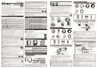
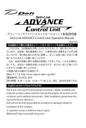
How to use the regular position bezel<br />
How to attach Mounting bracket set<br />
1) Cut the double sided tape as shown in figure 1.<br />
2) Insert convex part of the mounting bracket over the legs of the meter cup. Attach the mounting<br />
bracket to the meter cup with the bolt, nut, and washer included in the kit as shown in figure 2.<br />
3) Attach one piece of double sided tape and the buffer on the gauge as shown in figure 3. (Cut the<br />
buffer into suitable length when installing Φ 52(2 1/16”) series.)<br />
4) Pass the power supply wire and the sensor wire through the hole of the meter cup and connect them<br />
to the gauge.<br />
5) Place the gauge in the meter cup making sure that the wires are not sandwiched.<br />
6) Attach double sided tape on the back of the mounting bracket as shown in figure 4. Bend the<br />
mounting bracket to conform to the structure of the location where you intend to attach it.<br />
Confirmation<br />
Use appropriate dashboard cleaning liquids (commercially available) to clean the area<br />
where the double sided tape will be attached.<br />
<br />
Do not lay the gauge face down due to oil leakage. Angle "A" must be more than 90<br />
degrees.<br />
<br />
If the adherence of double sided tape is not enough, use commercial tapping screws.<br />
figure 1<br />
figure 4<br />
Mounting bracket<br />
(rear side)<br />
Nut<br />
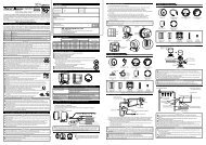
How to attach boost sensor<br />
Rubber hose<br />
Holes for screws<br />
(Φ4.4mm)<br />
Attach with clamps.<br />
(commercially available)<br />
Washer<br />
TURBO (DF065, DF115 series)<br />
Components<br />
figure 2<br />
Double<br />
sided tape<br />
Bolt<br />
[In case using screws]<br />
Buffer<br />
Use screws commercially available as needed.<br />
(c)<br />
Three-way joint<br />
(a)<br />
(b)<br />
figure 3<br />
Light blue<br />
3pins<br />
<strong>Gauge</strong> 1pc Boost sensor 1pc Sensor wire (2.58 1/5ft)<br />
1pc<br />
4mm x 3<br />
Three way joint<br />
1pc<br />
Mounting bracket set<br />
Double sided<br />
tape 1pc<br />
Red triangle<br />
Rubber hose (0.5m, 1 3/5ft)<br />
1pc<br />
Buffer<br />
1pc<br />
The red triangle can be used as an warning indicator.<br />
To move the position of the red triangle, remove the bezel<br />
once and then adjust the position and attach it again.<br />
Inside<br />
diameter<br />
4mm<br />
Meter cup 1pc<br />
Mounting<br />
bracket 1pc<br />
To sensor wire<br />
Attaching position<br />
of buffer<br />
Operation manual (this sheet) and warranty card are included other than the parts listed above. Keep them at hand.<br />
Surge tank<br />
Power supply wire<br />
(1m, 3 1/3ft) 1pc<br />
Regular position<br />
bezel 1pc<br />
M4 bolt, nut,<br />
washer 1pc<br />
Fuel regulator<br />
Sensor<br />
*Be sure to be installed facing side the<br />
hole down.<br />
1) The rubber hose attached to the sensor should be as short as possible. Attach the sensor with bolts<br />
(M6) in the engine compartment in an area where it will not be subject to excess heat or vibration.<br />
2) Access to the air pressure intake may be obtained between the surge tank and the fuel regulator.<br />
(A)Detach the vacuum hose from the surge tank side that has less pressure oscillations and connect<br />
it to the point (a) or (b) of the three way joint.<br />
(B)In order to connect the surge tank with three way joint, cut the required length of the hose from<br />
the included rubber hose.<br />
(C)Use the remaining rubber hose to connect the sensor to the three way joint.<br />
Warning<br />
To avoid disconnection of rubber hose and air leak, attach hose clamps or use tie-wraps to secure the<br />
adjacent hose in the engine compartment. Disconnected hose or air leak could cause damage to the engine.<br />
Confirmation<br />
The length of the included rubber hose is 0.5m. Please adjust appropriately.<br />
The included three-way joint can be used only for the piping inner diameter of Φ4 between the surge<br />
tank and fuel pressure regulator. In case of other than Φ4, use another joint that fits properly.<br />
The sensor must be installed being the rubber hose connection side faced down.<br />
For vehicles which have a solenoid valve between the surge tank and the fuel pressure regulator,<br />
place a three-way joint closer to the surge tank side than to the solenoid side.<br />
PRESS. (DF066, 116 series)<br />
Components<br />
<strong>Gauge</strong> 1pc<br />
Meter cup 1pc<br />
Mounting bracket set<br />
Double sided<br />
tape 1pc<br />
Pressure sensor<br />
(1/8PT) 1pc<br />
Regular position<br />
bezel 1pc<br />
Buffer<br />
1pc<br />
Red<br />
3pins<br />
Sensor wire (2.5m, 8 1/5ft)<br />
1pc<br />
Mounting<br />
bracket 1pc<br />
Power supply wire<br />
(1m, 3 1/3ft) 1pc<br />
M4 bolt, nut,<br />
washer 1pc<br />
Operation manual (this sheet) and warranty card are included other than the parts listed above. Keep them at hand.<br />
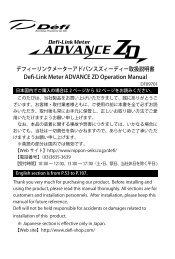
How to attach pressure sensor for oil pressure (Use a commercial sensor attachment.)<br />
Detach the original<br />
element.<br />
Engine<br />
Sensor attachment<br />
(commercially available)<br />
Thread size 1/8PT<br />
O ring<br />
(provided with commercial parts)<br />
Sensor<br />
Warning<br />
Engine<br />
Wind Teflon tape.<br />
Be sure not to twist.<br />
To sensor wire<br />
Be sure the sensor wire is not twisted when installing the sensor. The sensor wire will be cut.<br />
Oil spills by the installation work. Please replenish the engine with oil. The engine might overheat<br />
when oil is too little.<br />
To avoid oil leaks by installing of the sensors, use Teflon tape. Before driving, inspect oil blocks for<br />
leaks. Leaks could cause a fire or damage the engine.<br />
Do not install the sensor near oil pump. Do not install the sensor to pressure switch directly. Failure to<br />
do so could damage the sensor because the pressure pulsation is too big and exceed three times<br />
full-scale momentarily.<br />
To avoid the damage of the sensor wire, please fix the waterproof connector on the vehicle body and<br />
do not bend the sensor wire near the sensor.<br />
Confirmation<br />
The thread size of the pressure sensor is 1/8PT. Use a sensor attachment of 1/8PT. If the thread<br />
size of the sensor attachment for the pressure sensor is 1/8NPT, use a conversion adapter available<br />
from hardware stores.<br />
Tighten the sensor into the sensor attachment and then connect it to the sensor wire.<br />
How to attach pressure sensor for fuel pressure (Use a commercial three-way joint and hose unions.)<br />
Fuel pressure regulator<br />
*Cut the fuel feed pipe and<br />
Use a commercial<br />
install hose unions.<br />
conversion adapter in case<br />
*If the material used for the<br />
the inlet of the three-way<br />
inner surface of fuel feed<br />
joint is 1/8NPT.<br />
pipe is resin, a hose union<br />
may not be fixed. Check the<br />
Wind Teflon tape. material before cutting the<br />
fuel feed pipe.<br />
Fuel return pipe<br />
(low pressure)<br />
Hose union<br />
(commercially<br />
available)<br />
Three-way joint<br />
(commercially available)<br />
Warning<br />
Be sure the sensor wire is not twisted when installing the sensor. The sensor wire will be cut.<br />
Before cutting the fuel feed pipe, be certain to remove the gas cap to relieve any pressure built up in the<br />
fuel tank.<br />
When cutting the fuel feed pipe, be certain to discharge static electricity. Otherwise, there is a possibility<br />
of the ignition in gasoline.<br />
Wear glasses to protect eyes when cutting the fuel filter pipe.<br />
To avoid fuel leaks during installation of the sensor, use Teflon tape. Attach hose connection and fuel<br />
feed tubing with clamps. Inspect pipes and hose connections for leaks before driving.<br />
To avoid the damage of the sensor wire, please fix the waterproof connector on the vehicle body and<br />
do not bend the sensor wire near the sensor.<br />
Confirmation<br />
Be sure not to twist.<br />
Use a commercial<br />
conversion adapter in case<br />
the inlet of the sensor<br />
attachment is 1/8NPT.<br />
To sensor wire<br />
<br />
Sensor<br />
Fix tightly with clamps.<br />
(commercially available)<br />
Thread size 1/8PT<br />
Fuel feed pipe (high pressure)<br />
The sensor must be installed on the feed (high pressure) pipe side between the fuel tank and the<br />
fuel pressure regulator.<br />
*It is not possible to obtain accurate fuel pressure from the return (low pressure) side at the rear of the<br />
fuel pressure regulator.<br />
The thread size of hose unions and the three-way joint need to be 1/8PT. Use hose unions and a<br />
three-way joint of 1/8PT. If the thread size of the three-way joint is 1/8NPT, use a conversion adapter<br />
available from hardware stores.<br />
Tighten the sensor into the sensor attachment and then connect it to the sensor wire.
TEMP. (DF067, 117 Series)<br />
EXT.T. (DF068, 118 series)<br />
Repair Parts (for customer)<br />
Terms and Conditions (for customer)<br />
Components<br />
<strong>Gauge</strong> 1pc<br />
Meter cup 1pc<br />
Mounting bracket set<br />
Double sided<br />
tape 1pc<br />
Temperature sensor<br />
(1/8PT) 1pc<br />
Regular position<br />
bezel 1pc<br />
Buffer<br />
1pc<br />
Red<br />
2pins<br />
Sensor wire (3m, 10ft)<br />
1pc<br />
Mounting<br />
bracket 1pc<br />
Power supply wire<br />
(1m, 3 1/3ft) 1pc<br />
M4 bolt, nut,<br />
washer 1pc<br />
Operation manual (this sheet) and warranty card are included other than the parts listed above. Keep them at hand.<br />
How to attach temperature sensor for oil temperature (Use a commercial sensor attachment.)<br />
Detach the original element.<br />
Do not put the sensor in the side hole.<br />
The depth of the hole for the sensor<br />
must be more than 30mm (1.2”).<br />
Engine<br />
Sensor<br />
O ring<br />
(provided with<br />
commercial parts)<br />
Thread size 1/8PT<br />
Engine<br />
Sensor attachment<br />
(commercially available)<br />
Wind Teflon tape.<br />
Be sure not to twist.<br />
To sensor wire<br />
Warning<br />
Be sure the sensor wire is not twisted when installing the sensor. The sensor wire will be cut.<br />
Oil spills by the installation work. Please replenish the engine with oil. The engine might overheat<br />
when oil is too little.<br />
To avoid oil leaks by installing of the sensors, use Teflon tape. Before driving, inspect oil blocks for<br />
leaks. Leaks could cause a fire or damage the engine.<br />
To avoid the damage of the sensor wire, please fix the waterproof connector on the vehicle body and<br />
do not bend the sensor wire near the sensor.<br />
Confirmation<br />
The thread size of the temperature sensor is 1/8PT. Use a sensor attachment of 1/8PT. If the thread<br />
size of the sensor attachment for the temperature sensor is not 1/8PT, and you use a conversion<br />
adapter available from hardware store, note that the temperature is displayed lower than the actual<br />
value.<br />
The depth of the hole for the sensor must be more than 30mm (1.2”).<br />
Tighten the sensor into the sensor attachment and then connect it to the sensor wire.<br />
How to attach temperature sensor for water temperature (Use a commercial sensor attachment.)<br />
Upper hose<br />
Sensor attachment<br />
(commercially available)<br />
Radiator<br />
Sensor<br />
Attach tightly with clamps.<br />
(commercially available)<br />
Wind Teflon tape.<br />
Thread size 1/8PT<br />
Be sure not to twist.<br />
*Cut the upper hose and connect the<br />
sensor attachment between hoses.<br />
To sensor wire<br />
Components<br />
<strong>Gauge</strong> 1pc<br />
Fitting (1/8PT) 1pc<br />
Mounting bracket set<br />
Components<br />
<strong>Gauge</strong> 1pc<br />
Double sided<br />
tape 1pc<br />
Exhaust temperature<br />
sensor 1pc<br />
Meter cup 1pc<br />
Buffer<br />
1pc<br />
VOLT (DF070, 119 series)<br />
Power supply wire<br />
(1m, 3 1/3ft) 1pc<br />
Black<br />
2pins<br />
Sensor wire (2.58 1/5ft)<br />
1pc<br />
Regular position<br />
bezel 1pc<br />
Mounting<br />
bracket 1pc<br />
Meter cup 1pc<br />
Power supply wire<br />
(1m, 3 1/3ft) 1pc<br />
M4 bolt, nut,<br />
washer 1pc<br />
Operation manual (this sheet) and warranty card are included other than the parts listed above. Keep them at hand.<br />
How to attach exhaust temperature sensor for exhaust temperature<br />
Make a threaded screw<br />
hole (1/8PT).<br />
Fitting(a) Bushing<br />
Fitting(b)<br />
Exhaust manifold<br />
Mounting bracket set<br />
Thread size 1/8PT<br />
Exhaust temperature sensor<br />
Sensor wire<br />
1) Make a 1/8PT threaded screw hole in the exhaust manifold pipe. (Weld if the pipe wall thickness is not enough<br />
2) Dismantle the fitting. Do not crush the bushing inside the fitting.<br />
3) Tighten the fitting(a) to the hole of the exhaust manifold.<br />
4) Pierce the sensor through the fitting(b) and the busing.<br />
5) Insert the edge of the sensor into the fitting(a) and position it at the center of the exhaust pipe.<br />
6) Tighten the fitting(b).<br />
Warning<br />
To avoid personal injury, do not install the exhaust temperature sensor while the engine is hot.<br />
When making a hole, make sure no chip remains in the exhaust pipe or turbine. It may result in<br />
damage to the engine, exhaust pipe, or turbine.<br />
Confirmation<br />
The thread size of the fitting is 1/8PT. Make a threaded screw hole of 1/8PT.<br />
Tighten the sensor into the sensor attachment and then connect it to the sensor wire.<br />
Regular position<br />
bezel 1pc<br />
Item<br />
Fuse 0.3A (2pcs)<br />
Mounting Bracket set for <br />
Mounting Bracket set for <br />
Power Supply wire<br />
Boost Sensor<br />
Boost Sensor wire<br />
Pressure Sensor(1/8PT)<br />
Pressure Sensor wire<br />
Temp. Sensor(1/8PT)<br />
Temp. Sensor wire<br />
Exhaust Temp. Sensor<br />
Exhaust Temp. Sensor wire<br />
1/8PT Fitting for Exhaust Temp. Sensor<br />
Optional Parts (for customer)<br />
Item<br />
Boost Sensor extension wire 1m(3 1/3ft.)<br />
Pressure Sensor extension wire 1m(3 1/3ft.)<br />
Pressure Sensor extension wire 2m(6 3/5ft.)<br />
Temp. Sensor extension wire 1m(3 1/3ft.)<br />
Temp. Sensor extension wire 2m(6 3/5ft.)<br />
Exhaust Temp. Sensor extension wire 2m(6 3/5ft.)<br />
Model Number<br />
PDF06508G<br />
PDF06507G<br />
PDF07809G<br />
PDF06504H<br />
PDF06503S<br />
PDF06505H<br />
PDF00703S<br />
PDF06603H<br />
PDF00903S<br />
PDF05602H<br />
PDF01103S<br />
PDF06803H<br />
PDF01105G<br />
Troubleshooting (for customer and installation personnel)<br />
Warning<br />
If operation of the product seems unusual, inspect the product to confirm that there is no malfunction.<br />
If an operational problem has occurred, it could result in an accident.<br />
In addition to a general inspection of the product, use the following table to confirm proper operation of the unit.<br />
Condition Possible Cause Corrective Action<br />
A gauge lapses into the<br />
disconnection check mode.<br />
(Except VOLT gauge)<br />
A gauge lapses into the short<br />
circuit check mode. (Except<br />
VOLT gauge)<br />
A gauge doesn't operate.<br />
A gauge doesn't perform the<br />
opening mode.<br />
A gauge doesn't perform the<br />
closing mode.<br />
Dimmer is not working.<br />
Malfunctioning operation<br />
Disconnection of sensor or sensor wire<br />
Connector is unhooked.<br />
Incorrect wiring<br />
Sensor or sensor wire has a short<br />
circuit.<br />
Sensor or sensor wire is shorted to<br />
the vehicle body.<br />
Fuse on the power supply wire is<br />
blown out.<br />
Wiring of IGN wire or GND wire of<br />
the power supply wire to the vehicle<br />
is wrong.<br />
Fuse on the IGN wire of the power<br />
supply wire is blown out.<br />
Wiring of constant battery+ wire of<br />
the power supply wire to the vehicle<br />
is wrong.<br />
Fuse on the constant battery+ wire of<br />
the power supply wire is blown out.<br />
Wiring of ILM wire of the power<br />
supply wire to the vehicle is wrong.<br />
Wrong wiring of the power supply wire<br />
Model Number<br />
PDF06002H<br />
PDF06013H<br />
PDF00707H<br />
PDF06014H<br />
PDF00906H<br />
PDF01107H<br />
Check the disconnection of connectors<br />
and wires.<br />
Look for the point of short circuit with the<br />
following procedures.<br />
Step 1Unplug the sensor from sensor wire.<br />
The gauge lapses into the<br />
disconnection check mode.<br />
Short circuit of the sensor.<br />
The short circuit check mode<br />
continues. Go to Step 2<br />
Step 2Unplug the sensor wire from the gauge.<br />
The gauge lapses into the<br />
disconnection check mode.<br />
Sensor wire has a short circuit.<br />
Check the wiring.<br />
Do not share single fuse with multiple<br />
<strong>gauges</strong>. Every gauge requires<br />
independent fuse for IGN and +B line.<br />
Check the wiring.<br />
Replace the fuse of the power supply<br />
wire.<br />
Check the wiring.<br />
Replace the fuse of the power supply<br />
wire.<br />
Check the wiring.<br />
Check the wiring.<br />
If the problem is not solved after the remedies mentioned above are tried:<br />
Ask the installation personnel or the shop you purchased the gauge for inspection.<br />
Purchase new parts for replacing wear-out parts .<br />
Maintenance & Check/Warranty & Servicing<br />
Warranty cardTerms and conditions<br />
This product is delivered with this operation manual and a warranty card. Please read terms and conditions in<br />
this manual thoroughly and keep the warranty card in a safe place. Failure to show this warranty will void the<br />
warranty.<br />
Warranty period<br />
Limited one year warranty. The warranty period starts at the date of retail purchase by the original end-user<br />
purchase. Please confirm the warranty card is provided with the information of retail store where purchased.<br />
Please refer to Limited Warranty for details.<br />
Except in the case of defects, we shall not be liable for any trouble including violation, accident or improper<br />
wiring resulting from using this product.<br />
The warranty does not cover any unauthorized repair performed or caused to be performed by the end user.<br />
Such action can destroy or damage this product.<br />
Inspection<br />
Please ask the shop you purchased the product for inspection if any defect in product is suspected. We don't<br />
accept the order of fixing because <strong>Defi</strong> products require installation and wiring to the vehicle. In case you cannot<br />
go to the shop you purchased because of move-out or closure of shop, please ask the nearest <strong>Defi</strong> Distributor<br />
listed in the <strong>Defi</strong> website.<br />
For a repair/inspection service, take the warranty card and customer contact information with you.<br />
LIMITED PRODUCT WARRANTY AND LIMITED PRODUCT LIABILITY<br />
A. Limited Warranty<br />
a. Our sole obligation to you after the sale of a product is to replace, without charge, the product or any<br />
component thereof discovered to bee defective within a period of one (1) year from the purchasing<br />
date(the "Warranty Period"). You accept sole responsibility for the proper assembly operation and<br />
regular maintenance of the product. This limited warranty is void if any product is damaged by<br />
accident, misuse, improper installation, or abuse, including tampering or damage in transit. Further,<br />
this limited warranty is void if you sell or otherwise transfer a product to a third party, regardless of<br />
whether the transfer takes place within the Warranty Period.<br />
b. Out liability to you resulting from the sale of any product, including liability for any latent defects found<br />
within the Warranty Period, shall not exceed the total purchase price paid for the product by you.<br />
c. YOU UNDERSTAND AND AGREE THAT WE MAKE NO REPRESENTATIONS OR WARRANTIES OF<br />
ANY KIND, EXPRESS OR IMPLIED AS TO ANY MATTER WHATSOEVER, INCLUDING THE<br />
CONDITION OF THE PRODUCT OR ANY COMPONENT PARTS THEREOF, ITS<br />
MERCHANTABILITY OR ITS FITNESS FOR ANY PARTICULAR PURPOSE AND YOU ACCEPT IT,<br />
"AS IS," "WHERE IS."<br />
d. You also understand that we are not granting any express warranties, other than those stated herein.<br />
These include only those warranties enumerated in paragraph A. a. There are no other express<br />
warranties granted anywhere in these terms and conditions of sale, and you understand and agree to<br />
this fact as part of the bargained for exchange of this sale. Nowhere else, except as stated in this<br />
paragraph, in this contract is there intended, by either party, for there to be any express warranties<br />
granted to you.<br />
e. EXCEPT AS OTHERWISE PROVIDED HEREIN, WE SHALL NOT BE LIABLE FOR DAMAGES,<br />
INCLUDING SPECIAL, INCIDENTAL OR CONSEQUENTIAL DAMAGES WHETHER IN CONTRACT<br />
OR IN TORT ARISING OUT OF OR IN CONNECTION WITH THE PERFORMANCE OF ANY<br />
PRODUCT OR ANY COMPONENT PART THEREOF OR ITS USE BY YOU, AND WE SHALL NOT<br />
BE LIABLE FOR ANY SPECIAL, INCIDENTAL OR CONSEQUENTIAL DAMAGES ARISING OUT OF<br />
OR IN CONNECTION WITH YOUR USE OF THE PRODUCT.<br />
f. The warranty on this product is void if the product is modified, changed, adjusted or damaged. This<br />
product is to be used only in the ways for which it is designed and marketed for, any deviations from<br />
the intended uses will void the warranty and will excuse any possible liability of ours.<br />
g. You accept sole responsibility for the proper assembly, operation and regular maintenance of the<br />
product. This limited warranty is void if the product is damaged, changed, altered, or modified by<br />
accident, misuse, improper installation , or abuse, including tampering or damage in transit or while in<br />
use. YOU HAVE MADE AN INDEPENDENT INVESTIGATION OF THE PURCHASED<br />
COMPONENTS AND HAVE RELIED SOLELY ON YOU OWN INVESTIGATION, BARGAINING AND<br />
JUDGMENT IN REFERENCE THERETO. YOU ACKNOWLEDGE THAT YOU ARE NOT RELYING<br />
ON OUR SKILL OR JUDGMENT TO SELECT OR FURNISH GOODS SUITABLE FOR ANY<br />
PARTICULAR PURPOSE IN PURCHASING OUR PRODUCTS, YOU HAVE NOT RELIED OR<br />
ACTED UPON ANY REPRESENTATIONS OR WARRANTIES ON OUR PART NOT SPECIFICALLY<br />
SET FORTH HEREIN.<br />
h. This limited warranty gives you specific legal rights. You may also have other rights which vary from<br />
state to state. Some states do not enforce contractual limitations on how long an implied warranty<br />
lasts, when an action may be brought, or the exclusion or limitation of incidental or consequential<br />
damages, so the above limitations or exclusions may not apply to you.<br />
B. Modification Strictly Prohibited<br />
You understand and agree that any modification whatsoever , of the product, is strictly prohibited. You<br />
also agree not to modify the product in any manner regardless of whether such modification is<br />
material or immaterial. You also acknowledge that any modification of the product will void your<br />
limited warranty and bar you from any recovery or any remedy in a court of law or equity. Modification<br />
is strictly forbidden unless expressly authorized by our prior written approval. You agree not to make<br />
any modifications to the product and agree not to use any parts, components, or accessories in<br />
connection with the installation and use of the product that are not authorized and approved by us.<br />
C. Indemnity and Release<br />
a. You understand and agree that many factors beyond our control affect the operational safety of the<br />
product, including but not to limited to the installation of the product according to the instructions<br />
provided with the product.<br />
b. You also understand and agree that the installation of the product may involve the use of tools,<br />
equipment and construction methods which may present safety hazards which are beyond our<br />
control. You also understand and agree that the use of some of our products may create hazards and<br />
lower your ability to control your vehicle.<br />
c. You agree, as part of the bargained for exchange, to protect, indemnify, save harmless and release<br />
us, our authorized agents, employees, officers, directors and shareholders from and against all<br />
liabilities, obligations, claims, damages, penalties, causes of action, costs and expenses, imposed<br />
upon or incurred by or asserted against us or any assignees of ours, by you or any third party by<br />
reason of the occurrence or existence (or alleged occurrence or existence) of any use, installation,<br />
assembly, possession or operation of the product, any loss, damage or destruction of the product as<br />
of and after delivery(a "casualty occurrence"), and any other act or event relating to or caused by the<br />
product, including but not limited to, consequential or of the terms and conditions hereof, or any and<br />
all liability for property loss or damage, or any and all damage resulting from death or personal<br />
injuries, including loss of services which any person may sustain on account of, arising out of, or in<br />
connection with any use, maintenance, possession or operation of the product. In the event that any<br />
action, suit or proceeding is brought against us or any of our authorized agents, employees, officers,<br />
directors or shareholders by reason of any such occurrence, you will, upon our request and at your<br />
expense, resist and defend such action, suit or proceeding or cause the same to be resisted and<br />
defended by counsel designated and approved by us.<br />
Warning<br />
Be sure the sensor wire is not twisted when installing the sensor. The sensor wire will be cut.<br />
Coolant spills by the installation work. Please replenish the engine with coolant and bleed the air<br />
from the system, or the engine might overheat.<br />
To avoid water leaks during installation of the sensors, use Teflon tape. Attach the sensor<br />
attachment and upper hose with clamps. Inspect hose connections for leaks before driving.<br />
To avoid the damage of the sensor wire, please fix the waterproof connector on the vehicle body and<br />
do not bend the sensor wire near the sensor.<br />
Confirmation<br />
The thread size of the temperature sensor is 1/8PT. Use a sensor attachment of 1/8PT. If the thread<br />
size of the sensor attachment for the temperature sensor is not 1/8PT, and you use a conversion adapter<br />
available from hardware store, note that the temperature is displayed lower than the actual value.<br />
Tighten the sensor into the sensor attachment and then connect it to the sensor wire.<br />
Double sided<br />
tape 1pc<br />
Operation manual (this sheet) and warranty card are included other than the parts listed above. Keep them at hand.<br />
How to attach Volt gauge<br />
Buffer<br />
1pc<br />
Volt is displayed by connecting the power supply wire.<br />
Confirmation<br />
Mounting<br />
bracket 1pc<br />
M4 bolt, nut,<br />
washer 1pc<br />
Use the tube fuse of repair part when the fuse of the power supply wire is changed. Using a<br />
commercial fuse may affect the accuracy.<br />
Dimensions in mm (1mm=0.039in)<br />
<br />
<br />
<br />
<br />
<br />
<br />
<br />
<br />
<br />
<br />
<br />
<br />
<br />
<br />
<br />
<br />
<br />
<br />
<br />
<br />
<br />
<br />
<br />
<br />
<br />
<br />
<br />
<br />
<br />
<br />
Label<br />
The label sticked on the product is for the product traceability. Do not peel it off.<br />
Repairing<br />
When a repair is necessary, we will return the inspection result report through the store to you. After receiving a<br />
repair service request, we start repairing. Ask the store how much it costs and how long it takes to repair.<br />
Discarding the products<br />
Please dispose products in accordance with disposal laws, state laws and local government. A recycle label on<br />
the package indicates that the package is recyclable.<br />
<strong>Racer</strong> <strong>Gauge</strong> Operation Manual<br />
Issue First edition: September, 2011 Second edition: July, 2012<br />
ManufacturerNippon Seiki Co., Ltd.<br />
Contact Information Nippon Seiki Co., Ltd. <strong>Defi</strong> Business Division<br />
Address190-1 Fujihashi 1-chome, Nagaoka-shi, Niigata 940-2141 JAPAN<br />
URLhttp://www.defi-shop.com/<br />
Patent pendingPAT. 3624865PAT. 3365604