ADVANCE Control Unit Manual - Defi
ADVANCE Control Unit Manual - Defi
ADVANCE Control Unit Manual - Defi

Create successful ePaper yourself
Turn your PDF publications into a flip-book with our unique Google optimized e-Paper software.
デフィーリンクアドバンスコントロールユニット 取 扱 説 明 書<br />
<strong>Defi</strong>-Link <strong>ADVANCE</strong> <strong>Control</strong> <strong>Unit</strong> Operation <strong>Manual</strong><br />
DF07703<br />
日 本 国 内 でご 購 入 の 場 合 は 2 ページから 40 ページをお 読 みください。<br />
このたびは、 当 社 製 品 をお 買 い 上 げいただきまして、 誠 にありがとうご<br />
ざいます。お 客 様 ・ 取 付 業 者 様 ともに、ご 使 用 の 前 に 本 書 を 全 て 必 ずお 読<br />
みいただき、 取 付 後 も 常 にお 手 元 に 保 管 し、 正 しいお 取 り 扱 い 方 法 でご 愛<br />
用 いただけますようお 願 い 申 し 上 げます。<br />
なお、 本 品 の 装 着 に 関 する 事 故 や 弊 害 につきましては、いかなる 場 合 に<br />
おいても、 当 社 は 一 切 責 任 を 負 いかねますので、あらかじめご 了 承 いただ<br />
けますようお 願 い 申 し 上 げます。<br />
※ 英 語 の 部 分 は 国 内 では 無 効 です。<br />
【Web サイト】http://www.nippon-seiki.co.jp/defi/<br />
【 電 話 番 号 】(03)3835-3639<br />
【 受 付 時 間 】10:00 ~ 12:00、13:00 ~ 17:00( 土 ・ 日 、 祭 日 、 当 社 休 日 を 除 く 平 日 )<br />
English section is from P.41to P.83.<br />
Thank you very much for purchasing our product. Before installing and<br />
using the product, please read this manual thoroughly. All sections are for<br />
customers and installation personnels. After installation, please keep this<br />
manual for future reference.<br />
<strong>Defi</strong> will not be held responsible for accidents or damages related to<br />
installation of this product.<br />
※ Japanese section is effective only in Japan.<br />
【Web site】http://www.defi-shop.com/
もくじ Contents<br />
もくじ Contents・ ・・・・・・・・・・・・・・・・・・ 1<br />
1 安 全 ・ 取 り 扱 いに 関 するご 注 意 【 必 ずお 読 みください】・ ・2<br />
2 特 長 ・・・・・・・・・・・・・・・・・・・・・・・・ 8<br />
3ラインナップ・ 価 格 ・・・・・・・・・・・・・・・・・ 8<br />
4 仕 様 ・・・・・・・・・・・・・・・・・・・・・・・・ 10<br />
5 構 成 部 品 ・ 各 部 名 称 ・ 寸 法 ・・・・・・・・・・・・・・ 11<br />
6 取 付 方 法 ・・・・・・・・・・・・・・・・・・・・・・ 14<br />
7 使 用 方 法 ・・・・・・・・・・・・・・・・・・・・・・ 21<br />
8トラブルシューティング・・・・・・・・・・・・・・・ 34<br />
9 補 修 パーツ・オプションパーツ ・ ・・・・・・・・・・・ 37<br />
保 守 ・ 点 検 ・ 保 証 ・アフターサービス・・・・・・・・・ 38<br />
1 Safety Warning 【Please read carefully.】・ ・・・・・・ 41<br />
2 Product Features・ ・・・・・・・・・・・・・・・・・ 47<br />
3 List of Products ・ ・・・・・・・・・・・・・・・・・・ 47<br />
4 Specification・ ・・・・・・・・・・・・・・・・・・・ 49<br />
5 Parts List/Part Names/Dimensions・・・・・・・・・・・ 50<br />
6 Installation・ ・・・・・・・・・・・・・・・・・・・・ 53<br />
7 Operation・・・・・・・・・・・・・・・・・・・・・ 60<br />
8 Troubleshooting・・・・・・・・・・・・・・・・・・ 74<br />
9 Repair parts/Optional parts ・・・・・・・・・・・・・ 77<br />
Maintenance & Check/Warranty & Servicing・ ・・・・・ 78<br />
1
1 Safety Warning 【Please read carefully.】<br />
This product is a required for <strong>ADVANCE</strong> gauges and displays. This<br />
product alone does not operate. Please use this product with AD-<br />
VANCE gauges or displays. As for installation and operation, please<br />
refer to the manual for the gauges and displays as well.<br />
This product is an additional product for providing information to automobile<br />
users about engine conditions and other important factors. When installing<br />
and operating this product, be sure to read the cautionary items of this operation<br />
manual as well as those given in the operation manual for the vehicle in<br />
which this product will be installed. Please obtain a full understanding of the<br />
cautionary items and use the product accordingly.<br />
In the event that this product (or the vehicle in which it is installed) is lent to or<br />
transferred to another person, please be sure this operation manual and warranty<br />
card accompany the product.<br />
In this manual, the degree of hazard arising from actions such as improper<br />
operation is separated into the 3 levels "Danger," "Warning," and "Caution."<br />
In addition, instructions that must be followed for safe and proper use of this<br />
product as well as practices that must be maintained are marked with a "Confirmation"<br />
heading. Please read and become familiar with these sections.<br />
Indicates the imminent dangerous situation of death or serious<br />
injury if the product is mishandled<br />
Danger<br />
Indicates the possibility of death or serious injury if the product<br />
is mishandled.<br />
Warning<br />
Indicates a conceivable source of personal injury or damage<br />
Caution<br />
to equipment if the product is improperly operated.<br />
Indicates an instruction that must be performed or practice<br />
Confirmation<br />
that must be maintained.<br />
Properties for safety warning<br />
Indicates attention needs to be paid. (Including warnings)<br />
Prohibited Indicates restricted actions. (PROHIBITED actions)<br />
Must<br />
Indicates actions that need to be carried out. (MUST actions)<br />
41
■ Before handling (for installation personnel)<br />
Danger<br />
Ensure that the vehicle will remain stationary and turn off the engine before<br />
installing this product. Failure to do so could result in a fire, and could make<br />
the vehicle move during installation.<br />
Remove the key from the ignition and disconnect the negative (-) battery<br />
terminal prior to installation of this product. Failure to do so could result in<br />
a fire caused by an electrical short circuit.<br />
Take care not to install this product in a way that interferes with safety equipment<br />
such as seat belts and air bag systems or vehicle operation equipment<br />
such as engine controls, steering wheel and brake systems. Interference with<br />
normal operation of the vehicle can result in an accident or fire.<br />
Solder or use a solderless connector for wiring connections and make sure<br />
connections are insulated. In areas where there could be tension or sudden<br />
impacts on the wiring, safeguard the wiring with corrugated tubing or<br />
other shock absorbent material. Accidental shorts can cause fires.<br />
While wiring power supply wire, to avoid the risk of electrical shock or fire,<br />
be sure to confirm that there is no disconnection or breakage of wire. Poor<br />
connection can result in short-circuit, electrical shock, fire, or other hazards.<br />
The ignition-switched +12V(IGN) line must be connected to the vehicle's<br />
ignition-switched wire with a fuse of 30A or less. High-capacity fuse(more<br />
than 30A) will not blowout even with an abnormal current flow and may<br />
cause fire.<br />
Discontinue use of this product if a blowout of the fuse has occurred. Continued<br />
use while the condition exists could result in an accident, fire, or<br />
damage to the vehicle.<br />
Use the tube fuse of regulated capacity when the fuse of the power wire is<br />
changed. Using a fuse that exceeds regulated capacity may cause fire.<br />
Do not install the product in wet places. It may result in a fire caused by an<br />
electrical short circuit.<br />
Discontinue use of this product if the product doesn't operate or operates<br />
improperly. Continued use while the condition exists could result in an accident<br />
or damage.<br />
42
Warning<br />
Carefully consider the installation location and driver's operation of the<br />
product before installation. Do not install the product where it interrupts<br />
driving and the safety deices of vehicle such as air bags. Be sure not to<br />
install the unit where it could fall. Improper installation or operation could<br />
cause the product to fall and damage the vehicle or cause serious danger<br />
by impeding driving.<br />
Do not disassemble or modify this product. Such actions can<br />
not only damage or destroy the product but also will void the Disassemble/<br />
warranty.<br />
Modify<br />
Do not perform installation of this product immediately after the engine has<br />
been switched off. The engine and exhaust system are extremely hot at this<br />
time and can cause burns if touched.<br />
Ensure that the wiring of this product does not have an adverse impact on<br />
the other wiring of the vehicle. Before tapping speed or engine rev signal<br />
from the ECU, please make sure that you have connected power cables<br />
inside power supply wire properly. Then confirm that the DC Source LED<br />
is lighted with ignition on. If it is functioning normally, remove negative<br />
terminal connector from battery and go ahead with wiring procedure.<br />
Incorrect wiring may destroy your ECU, ignition system and other engine<br />
management devices.<br />
Please keep children and infants away from the installation area. Children<br />
may swallow small parts or be injured in other ways.<br />
Do not install this product in the area where safety equipment such as air<br />
bags are mounted. This may cause more injuries in the event of accident.<br />
Caution<br />
This product is designed for use on 12V vehicles. Do not install<br />
this product on vehicles with 24V systems.<br />
Insulate any unused wires. If any wires or connectors loosen during installation,<br />
please make sure they are correctly reattached.<br />
Do not drop any of the components of this product. It may result in damage<br />
to the product.<br />
43<br />
24V
Do not apply excessive force on switches/terminals. It may result in damage<br />
to the product.<br />
Do not use wires other than the provided wires.<br />
Do not attach wires on the body of the vehicle or engine parts as this may<br />
result in damage to the product.<br />
Install wires away from ignition and also radio signal frequency interference<br />
as this could cause the gauges to malfunction.<br />
Please set it up so that the equipment such as the wireless machines and<br />
cellular phones that emit electric waves should not touch the unit. It may<br />
result in incorrect operation.<br />
Do not place wires near the engine, exhaust pipe or turbine. It may result in<br />
damage or fusion of wires.<br />
Make sure the waterproof processing is done when diverging wires in the<br />
engine compartment.<br />
Over 90°<br />
Do not lay the gauge face down due to oil leakage.<br />
A<br />
Angle "A" must be more than 90 degrees.<br />
When installing the sensor, do not bend the wire near the sensor body.<br />
Wear gloves to avoid burns when soldering and cuts when installing wires,<br />
sharp edges of parts.<br />
Do not expose the unit to moisture, dust or direct sunlight, or place product<br />
directly in front of heat vents.<br />
Install sensors away from hot or wet places.<br />
When using sunshade, put sunshade between products and windshield to<br />
avoid direct sun exposure .<br />
Use the dried soft cloth for cleanup. Do not use the cleaner except for the<br />
neutral detergent. It results in trouble.<br />
Do not pull the wires out of connectors forcefully. The<br />
connectors may be broken and the wires may be cut.<br />
When pulling out the wires, press the lock firmly to unclip<br />
the locks of connectors.<br />
Do not install gauges, including this product, into the passenger side or<br />
center of the dashboard. It doesn't meet vehicle safety standards.<br />
44
Confirmation<br />
Be sure to follow all instructions in this manual to ensure safe installation<br />
and operation of the product.<br />
When the negative (-) battery terminal is disconnected, equipment such<br />
as clocks and audio components having internal memory may lose their<br />
memory data. Follow the operation manual of each component to reset<br />
data after installation of this product.<br />
After installation is complete, return this operation manual, warranty card,<br />
and the package along with the warranty to the customer .<br />
The gauge pointer may not be in the proper position when you purchase<br />
the product. Normal function will resume when power is connected.<br />
Please confirm with the maintenance book that the car manufacturer issued<br />
when installing and detaching genuine parts.<br />
Before tapping wires, check the voltage of the existing wire. After tapping<br />
the wire, check the voltage of the tapped wire again to confirm whether<br />
you have tapped into the proper place.<br />
If car navigation system or car television is installed in vehicle, gauges and<br />
wires of this product need to be kept as far away as possible from the wiring<br />
and installing positions of car navigation system or car television. Failure to<br />
do so may result in interference of television display(VHF).<br />
On no event will Nippon Seiki Co., Ltd. be liable to you for any damages or<br />
losses of genuine parts for your vehicle while installing.<br />
■ About Installation and Operation (for customer and installation personnel)<br />
Warning<br />
Please have this product installed by store professional or dealer where it<br />
was purchased. Installation by the customer will void the warranty.<br />
Do not disassemble or modify this product. Such actions will<br />
not only void the warranty but also damage or destroy the<br />
Disassemble/<br />
product .<br />
Modify<br />
In order to ensure safe driving, check the information on the gauge only for<br />
a short period of time. Looking at the display for a long period of time could<br />
distract attention from the road and result in an accident.<br />
45
Discontinue use of this product if the gauge doesn't operate, water gets<br />
into the unit, or smoke or a strange odor comes from the unit. If such a condition<br />
occurs, contact the store or installation personnel as soon as possible.<br />
Continued use while the condition exists could result in an accident or fire.<br />
Do not operate while driving.<br />
Fix the switch unit and other parts tightly to the vehicle to avoid children's<br />
accidentally swallowing them.<br />
Do not use the TIME ATTACK function of <strong>ADVANCE</strong> ZD in open roads. It is<br />
only for closed courses.<br />
Caution<br />
On no event will Nippon Seiki Co., Ltd. be liable for any damages arising out<br />
of the use or inability to use the product, even if Seiki Co., Ltd. has been<br />
advised of the possibility of such damage.<br />
Do not pull the wires out of connectors forcefully. The connectors may be<br />
broken and the wires may be cut. When pulling out the wires, press the<br />
lock firmly to unclip the locks of connectors.<br />
Confirmation<br />
This product cannot be linked to the previous version of <strong>Defi</strong>-Link System.<br />
The information displayed on this product are for reference purposes only.<br />
Please drive according to the indication of vehicle's originally equipped instruments.<br />
Do not connect more than one gauge of the same variety. (Ex. You can NOT<br />
connect 2 turbo gauges together.)<br />
This product can be used only on 1, 2, 3, 4, 5, 6, and 8 cylinder vehicles with<br />
4 cycle engine. This product cannot be used on diesel vehicles.<br />
Please check the installed product regularly. Durability might deteriorate<br />
according to use conditions, etc.<br />
46
2 Product Features<br />
Interactive communication advanced system is implemented.<br />
Up to 7 <strong>ADVANCE</strong> gauges and displays in all can be controlled.<br />
Gauges can be controlled from distance with the included switch unit. The<br />
illumination color is white.<br />
By connecting <strong>ADVANCE</strong> ZD to the <strong>ADVANCE</strong> system, the illumination of<br />
<strong>ADVANCE</strong> BF and CR gauges is controlled automatically.<br />
Opening and ending modes can be selected from 2 variations.<br />
The installation of additional gauges is easy. Just connect it to other gauge<br />
and attach the sensor to <strong>ADVANCE</strong> <strong>Control</strong> <strong>Unit</strong>.<br />
Self-diagnosis system turns on the warning display to indicate any wire disconnection,<br />
short circuit and serial communication errors.<br />
Warning by buzzer sound when the warning display is on (buzzer sound<br />
can be turned on / off).<br />
Peak value and warning value during driving are stored. Driving data can be<br />
stored and replayed up to 3 minutes.<br />
Mounting kits are provided with gauges and displays.<br />
With both fuel pressure and turbo sensors installed, differential pressure<br />
can be monitored on the fuel pressure gauge or <strong>ADVANCE</strong> ZD.<br />
3 List of Products<br />
Product name<br />
<strong>Defi</strong>-Link <strong>ADVANCE</strong> <strong>Control</strong> <strong>Unit</strong><br />
Product No.<br />
DF07703<br />
■ <strong>ADVANCE</strong> CR gauges<br />
Φ 52 series<br />
Product name Display range White Dial Black Dial<br />
Turbo2.0 -100kPa ~ +200kPa DF07801 DF07802<br />
Turbo1.2 -100kPa ~ +120kPa DF07901 DF07902<br />
In-Mani Press ※ -100kPa ~ +20kPa DF08001 DF08002<br />
Oil Press 0 ~ 1000kPa DF08101 DF08102<br />
Fuel Press 0 ~ 600kPa DF08201 DF08202<br />
Oil Temp 50 ~ 150℃ DF08301 DF08302<br />
Water Temp 20 ~ 120℃ DF08401 DF08402<br />
Exhaust Temp 200 ~ 1100℃ DF08501 DF08502<br />
47
■ <strong>ADVANCE</strong> CR gauges<br />
■ <strong>ADVANCE</strong> BF gauges<br />
Φ 60 series<br />
Product name Display range White Dial Black Dial<br />
Turbo2.0 -100kPa ~ +200kPa DF08601 DF08602<br />
Turbo1.2 -100kPa ~ +120kPa DF08701 DF08702<br />
In-Mani Press ※ -100kPa ~ +20kPa DF08801 DF08802<br />
Oil Press 0 ~ 1000kPa DF08901 DF08902<br />
Fuel Press 0 ~ 600kPa DF09001 DF09002<br />
Oil Temp 50 ~ 150℃ DF09101 DF09102<br />
Water Temp 20 ~ 120℃ DF09201 DF09202<br />
Exhaust Temp 200 ~ 1100℃ DF09301 DF09302<br />
Tachometer 0 ~ 9000rpm DF09403 DF09404<br />
Φ 60 series<br />
Product name Display range<br />
White Amber Red Blue<br />
Model Model Model<br />
Turbo2.0 -100kPa ~ +200kPa DF09901 DF09902 DF09903<br />
Turbo1.2 -100kPa ~ +120kPa DF10001 DF10002 DF10003<br />
In-Mani Press ※ -100kPa ~ +20kPa DF10101 DF10102 DF10103<br />
Oil Press 0 ~ 1000kPa DF10201 DF10202 DF10203<br />
Fuel Press 0 ~ 600kPa DF10301 DF10302 DF10303<br />
Oil Temp 50 ~ 150℃ DF10401 DF10402 DF10403<br />
Water Temp 20 ~ 120℃ DF10501 DF10502 DF10503<br />
Exhaust Temp 200 ~ 1100℃ DF10601 DF10602 DF10603<br />
Tachometer 0 ~ 9000rpm DF10704 DF10705 DF10706<br />
Product Name<br />
<strong>Defi</strong>-Link Meter <strong>ADVANCE</strong> ZD<br />
Product No.<br />
DF09701<br />
This product is a required for <strong>ADVANCE</strong> gauges and displays. This product<br />
alone does not operate. Please use this product with gauges or displays<br />
listed above. As for installation and operation, please refer to the manual for<br />
gauges and displays as well.<br />
※ In-Mani Press is an abbreviation of Intake Manifold Pressure.<br />
48
4 Specification<br />
■ Power supply voltage 10V ~ 16V DC(For 12V vehicle)<br />
■ Current Consumption<br />
Maximum value in case 7 gauges or displays are connected<br />
+B line 2A(IGN ON)<br />
5mA(IGN OFF)<br />
ILM line 800mA<br />
■ Illumination color<br />
<strong>Control</strong> <strong>Unit</strong> DC Source LED:blue.<br />
Switch unit:white (while illumination is on)<br />
Switch unit D mark for differential pressure:blue<br />
■ Applicable number of cylinders<br />
1・2・3・4・5・6・8 (4cycle)<br />
■ Temperature range(Under 80% relative humidity) <strong>Unit</strong>: ℃ (°F)<br />
Storage<br />
Operational<br />
CR/BF/ZD -30 (-22) ~ +80 (176) -20 (-4) ~ +60 (140)<br />
<strong>ADVANCE</strong> <strong>Control</strong> <strong>Unit</strong> -30 (-22) ~ +80 (176) -20 (-4) ~ +60 (140)<br />
Switch <strong>Unit</strong> -30 (-22) ~ +80 (176) -20 (-4) ~ +60 (140)<br />
Boost sensor -30 (-22) ~ +100 (212) -30 (-22) ~ +80 (176)<br />
Press. sensor -30 (-22) ~ +140 (284) -30 (-22) ~ +120 (248)<br />
Temp. sensor -30 (-22) ~ +150 (302) -20 (-4) ~ +150 (302)<br />
Exhaust Temp. sensor -30 (-22) ~ +130 (266) -30 (-22) ~ +130 (266)<br />
※ The upper temperature limit of sensor connectors is 105℃ (221°F) .<br />
※ The sensing part of exhaust temp. sensor is not included in the temperature<br />
range above.<br />
49
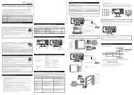
5 Parts List/Part Names/Dimensions<br />
5 -1. Parts List<br />
<strong>ADVANCE</strong> <strong>Control</strong> unit<br />
1pc<br />
Switch unit<br />
Wire1.5m(5ft) 1pc<br />
Power source wire<br />
1m(3 1/3ft.) 1pc<br />
Meter wire<br />
2m(6 3/5ft.) 1pc<br />
Accessories<br />
Double sided tape<br />
1pc<br />
Tie wrap 2pcs Solderless connector<br />
4pcs<br />
Clip 1pc Nut 4pcs Bolt 4pcs<br />
Operation manual (this booklet) and warranty card are included with the<br />
parts listed above.<br />
50
5 -2. Part Names & Dimensions of <strong>Control</strong> <strong>Unit</strong> in mm(inches)<br />
Screw holes(4 places)<br />
22(2.05")<br />
1 2 3 4 5 6 7 8 9 10 11<br />
51(2")<br />
26.3(1.04")<br />
104(4.1")<br />
Dip switch<br />
153.2(6.03")<br />
DC source(wiring check) LED (blue)<br />
Meter wires can be connected to both 10 and 11 . To protect against short-circuit<br />
between two terminals, the convex connector is inserted into the concave connector<br />
11 at the factory prior to shipment. If You don't use 11 , do not remove<br />
the convex connector. When using 11 , please pull out the convex connector<br />
by pressing the lock, and then connect the meter wire.<br />
15(0.59")<br />
Slots for screw<br />
nut (4 places)<br />
● Connectors for wires<br />
● Dip switch 1&2<br />
1 Switch unit(white)<br />
1: Warning buzzer sounds ON/OFF<br />
2 Speed&Tachometer signal wire(blue) change<br />
3 Exhaust temp sensor wire(black) 2: Opening・Closing modes<br />
4 Water temp sensor wire(pink)<br />
selection(A/B)<br />
5 Oil temp sensor wire(red)<br />
6 Fuel press sensor wire(red)<br />
7 Oil press sensor wire(white)<br />
8 Turbo/In-Mani sensor wire(light blue)<br />
9 Power source wire(beige)<br />
10 Meter wire(white) 11 Meter wire(white)<br />
51
5 -3. Part Names & Dimensions of Switch unit in mm(inches)<br />
80(3.15")<br />
16(0.63")<br />
78.4(3.09")<br />
7(0.28")<br />
Differential pressure<br />
LED(blue)<br />
● Backside of switch unit<br />
Left button Right button<br />
Middle button<br />
Applying position of<br />
double-sided tape<br />
26.2(1.03")<br />
Slide switch<br />
(REAL/PLAY/SET from the top)<br />
Lot No. label<br />
Do not peel the labels<br />
sticked on the product and<br />
warranty card.<br />
● Buttons and slide switch<br />
Operation of gauges is handled by 3 buttons and 1 slide switch. By sliding the<br />
switch position, the functions of buttons change.<br />
● Slide switch<br />
In this manual, positions of the slide switch are illustrated as follows:<br />
REAL(upper): for Real mode operation<br />
<br />
PLAY(middle): for operation to replay recorded data <br />
SET(lower): for operation to set up<br />
<br />
● Buttons<br />
Each button has three marks(upper, middle, and lower position) in accordance<br />
with positions of slide switch. In this manual, each button is illustrated as follows:<br />
Left Middle Right<br />
Left button: or or from the top<br />
Middle button: or or from the top<br />
Right button: or or from the top<br />
52
6 Installation<br />
Confirmation<br />
Please refer to how to install gauges, displays, and sensors of each manual<br />
as well as this manual.<br />
6 -1. Installation diagram<br />
<br />
<br />
<br />
<br />
<br />
<br />
<br />
<strong>ADVANCE</strong><br />
<strong>Control</strong> <strong>Unit</strong><br />
CR<br />
BF<br />
<br />
ZD<br />
ZD<br />
CR<br />
BF<br />
CR<br />
The meter wire can be connected to both two connectors of METER OUTPUT.<br />
Up to 7 gauges and displays in all can be connected to one control unit. (Ex. If<br />
7 gauges are connected to one line, none can be connected to the other line.<br />
If three gauges are connected to one line, up to 4 gauges can be connected to<br />
the other line.)<br />
Do not connect more than one gauge of the same variety. (Ex. You can NOT<br />
connect 2 turbo gauges together.) However, several ZDs can be connected.<br />
53
6 -2. Procedure<br />
1. Confirm the contents.<br />
⇒ Please refer to operation manuals included with components and each<br />
gauge.<br />
2. Confirm and prepare the necessary parts for installation.<br />
⇒ Refer to the operation manual included with each gauge.<br />
Please purchase commercially available attachment parts.<br />
3. Confirm the location of the power source(Battery, GND, IGN, ILM) and the<br />
sensor installation.<br />
4. Disconnect the negative(-) battery terminal.<br />
5. Connect the power supply wire to vehicle.<br />
⇒ Refer to 6 -3. How to solder・How to use the solderless connectors.<br />
Warning<br />
Do not connect the IGN wire to the ACC (power source for accessory) wire.<br />
Failure to do so way lead to a malfunction or accident.<br />
6. Connect the power supply wire to the control unit. Connect the negative<br />
battery terminal and turn the ignition on. Then confirm DC SOURCE LED<br />
lights up, which is on the front of the control unit.<br />
Confirmation<br />
If the power source wire is wired incorrectly, LED won't light. If LED doesn't<br />
light, please confirm wiring again.<br />
7. Disconnect the negative battery terminal and install each sensor.<br />
⇒ Refer to the operation manual included with each gauge.<br />
8. Connect the sensor and the sensor wire. Then connect to the control unit.<br />
54
9. To confirm the wiring and connection, connect gauges and displays to the<br />
control unit temporarily by using meter wires. Do not fix the gauge at this<br />
stage.<br />
Do not remove the convex connector if you use only one METER OUTPUT<br />
connector to protect against short-circuit between two terminals.<br />
10. Connect the negative battery terminal.<br />
11. Confirm that the DC SOURCE LED is on when the ignition is on. If the<br />
power supply wire is wired correctly, the DC SOURCE LED of the control unit<br />
lights in blue. And also look see that CR gauges' illumination lights up/BF<br />
gauges' illumination darkens/ZD's switch illumination lights up when the<br />
illumination switch of the vehicle is on.<br />
● The DC SOURCE LED is not on: The power supply is not taken.<br />
→ Turn the ignition off, then please confirm the wiring of the power supply wire.<br />
● The warning LED of gauge is blinking or the warning LED and peak LED are<br />
blinking at the same time: disconnection, short circuit, or communication<br />
error is occurred.<br />
⇒ Refer to 7 -3-2. Error displays of wire disconnection, short circuit, and<br />
serial error.<br />
→ Turn the ignition off, then please confirm the wiring of the sensor and the<br />
sensor wire.<br />
Warning<br />
If the wiring defects are not found, it is probable that there is a defect in the<br />
product. Please detach the product immediately and ask for inspection. It<br />
may damage the vehicle.<br />
⇒ Refer to Maintenance & Check & Servicing.<br />
12. Turn the ignition OFF.<br />
55
13. Disconnect the meter wire from the gauge, and attach the gauge by using<br />
mounting bracket. Confirm it is installed firmly, then connect the meter wire<br />
again.<br />
⇒ Refer to each gauge operation manual<br />
14. Connect the switch unit to the control unit and fix the switch unit with<br />
double sided tape. Before attaching it , make sure the surface is clean.<br />
⇒ Refer to 5 -3. Part Names & Dimensions of Switch unit in mm(inches).<br />
15. Set 2 dip switches of the control unit.<br />
● Dip switch 1: Setting the buzzer sound ON/OFF.<br />
● Dip switch 2: Select the opening/ending mode from A or B when the<br />
ignition is on/off.<br />
⇒ Refer to 5 -2. Part Names of <strong>Control</strong> <strong>Unit</strong> in mm(inches), 7 -6-2. Set the<br />
warning buzzer ON/OFF, and 7 -2-1. Change of Opening mode / Ending mode.<br />
16. After setting is done, fix the control unit with attached nuts and bolts and<br />
commercial mounting bracket.<br />
Confirmation<br />
Gauges, including this product, are not waterproof. Please do not install<br />
gauges near the vehicle floor or in wet areas.<br />
56
Use mounting brackets with thickness of 3mm(0.1") and under.<br />
Do not use other than the supplied bolts. Use of other bolts may damage<br />
the inside of the control unit.<br />
The control unit contains buzzer. So it may difficult to hear the sounds if the<br />
control unit is installed inside the dashboard or far from driver's seat.<br />
It is possible to change the setting later. In order to change later, please fix<br />
the control unit so as to operate the dip switch.<br />
17. Final confirmation of install completion<br />
Warning<br />
Please be sure to check the following list; otherwise, there is a possibility<br />
that a serious accident may occur.<br />
□ Ensure that all hoses and tubing are permanently attached. Also ensure that<br />
there is no liquid or exhaust leakage.<br />
□ Check that the sensor and wires are not interfering with the engine operation.<br />
□ Ensure that the gauge and wires are tightly attached, so they don't come<br />
loose and hinder driving.<br />
□ Check that all wires disconnected from the vehicle during installation have<br />
been properly reattached.<br />
Warning<br />
After installation, check that no materials or tools remain in the driver's seat<br />
or the engine compartment. If there are tools left at the feet of the driver's<br />
seat, this may cause a driver to lose control of brake because of tools or<br />
materials caught under the brake pedal. If there are tools in the engine<br />
compartment, the engine may break.<br />
57
□ Ensure that the negative battery terminal is tightly attached. Close the hood<br />
properly.<br />
This concludes the installation process.<br />
Confirmation<br />
The protection film is attached to <strong>ADVANCE</strong> <strong>Control</strong> <strong>Unit</strong> and the switch<br />
unit. Please peel off before using. It may be sticked by aging of the glue.<br />
58
6 -3. How to solder・How to use the solderless connectors<br />
Caution<br />
Wear protective gloves to avoid getting burned during soldering.<br />
Soldering is a better choice for wiring. Make sure no loose connection is<br />
found.<br />
● How to solder<br />
● How to use the solderless connectors<br />
Confirmation<br />
The solderless connectors that come with the product are for cable core of<br />
0.3mm ~ 0.75mm diameter. Use them within the range.<br />
Do not use the solderless connectors on wires that have thicker cable core<br />
than 0.75mm diameter. Cable core might be broken and produce heat.<br />
59
7 Operation<br />
In this instruction, there are two kinds of ways to press buttons, "press" and<br />
"press long." For "press," press the button for less than 1 second. For "press<br />
long," press the button for more than 1 second.<br />
7 -1. Setting and checking of operations<br />
1. Turn the ignition on and confirm the DC Source LED on the control unit is<br />
lighted up.<br />
⇒ Refer to 6 Installation.<br />
2. Confirm that the opening mode is performed.<br />
⇒ Refer to 7 -2. Opening mode / Ending mode.<br />
3. Confirm that there is no error message of wire disconnection/short circuit<br />
on the gauges and ZDs.<br />
⇒ Refer to 7 -3-2. Error displays of wire disconnection, short circuit, and serial error.<br />
If an error is displayed<br />
→ Turn the ignition off immediately, and then confirm the wiring of the<br />
sensor and the sensor wire.<br />
4. If the tachometer is installed, please set the number of cylinders and the response.<br />
If ZDs are installed as well, settings for tachometer need to be done in System<br />
Setup Mode of ZD. The settings of ZD are applied to other tachometers<br />
connected to the <strong>ADVANCE</strong> System. Refer to ZD manual for setting. If you<br />
don not install either ZD or tachometer, go to next step.<br />
⇒ Refer to 7 -4. Setting number of cylinders mode and 7 -5. Setting<br />
Tachometer response mode.<br />
5. Set warning values for all the connected gauges and ZDs. And then select<br />
illumination color for CR gauges. Warning values for gauges and ZDs are<br />
set at the same time.<br />
⇒ Refer to 7 -6-3. Change the illumination color.<br />
6. Confirm gauges and ZDs function normally. Setting is finished by confirming<br />
the operations.<br />
Warning<br />
Please set while the vehicle is stopped.<br />
60
7 -2. Opening mode / Ending mode<br />
When the ignition is turned on, gauges and ZDs perform opening mode.<br />
When the ignition is turned off, gauge and ZDs perform ending mode and<br />
then the power supplies of the control unit, gauges, and ZDs are shut off.<br />
Confirmation<br />
Depending on vehicles, the ignition is not turned off immediately after the<br />
key is turned off. In this case, ending mode doesn't start until the ignition is<br />
turned off.<br />
If the ignition is turned off during setting, the setting data will not be saved.<br />
If the power wire is wired correctly, the DC Source LED lights in blue from<br />
the beginning of opening mode. If it stays off or is blinking, turn the ignition<br />
off and check the wiring.<br />
⇒ Refer to 6 Installation.<br />
7 -2-1. Change of Opening mode / Ending mode<br />
Opening and ending modes can be selected from A type (simple) and B type<br />
(special) by sliding the dip switch 2 on the control unit.<br />
Both types consists of lighting/blinking of peak & warning LED, the dial illumination,<br />
and sequential indicators of ZD, besides pointer movement and digital<br />
display on ZD. Try both types!<br />
Please slide the switch when the ignition is off. The modes for all the connected<br />
gauges and ZDs are changed at the same time.<br />
It might be hard to see the dial illumination depending on outside light<br />
level.<br />
7 -3. Real Mode (slide switch position : )<br />
After the opening mode finishes, the gauge shifts to Real mode. The real-time<br />
vehicle conditions are displayed during Real mode.<br />
61
7 -3-1. Warning display<br />
If the gauge reaches or exceeds the value set for warning, the warning LED<br />
goes on. In case of oil pressure and fuel pressure, when the gauge reaches or<br />
falls below the value set for warning, the warning LED goes on. The zone that<br />
the warning item is displayed is highlighted on ZD display. If the buzzer sound<br />
setting is on, the buzzer sounds at the same time as well.<br />
7 -3-2. Error displays of wire disconnection, short circuit, and serial error<br />
If there are disconnection of wire and/or sensor, or short circuits of wire and/<br />
or sensor, the warning LED blinks. Error messages are displayed on ZD display.<br />
Once the error message is displayed, the warning LED keeps blinking until the<br />
ignition is turned off. Please turn off the ignition immediately and check the<br />
wiring of sensors and wires. The short-circuit error displays for oil pressure and<br />
fuel pressure are displayed only during short-circuiting.<br />
If the communication between gauges/ZDs and the control unit is failed, serial<br />
error massage is displayed and warning and Peak LEDs blink at the same time.<br />
Disconnection(Warning LED blinks)<br />
Short-circuit(Warning LED blinks)<br />
ON<br />
OFF<br />
Peak LED<br />
Warning LED<br />
Serial communication error<br />
(Warning & Peak LED blinks simultaneously)<br />
If an error is displayed, turn the ignition off immediately, and then confirm<br />
the wiring of the sensor and the sensor wire. If any defects are not found,<br />
please ask the shop for inspection.<br />
7 -3-3. Illumination<br />
【<strong>ADVANCE</strong> CR gauges】<br />
The illumination of CR gauges are turned on/off being interlocked with the<br />
vehicle illumination switch.<br />
62
By pressing button several times during Real mode, Record<br />
mode or Playback mode, the gauge illumination is turned off even if the<br />
vehicle illumination is on. (Illumination cancel)<br />
【<strong>ADVANCE</strong> BF gauges】<br />
The brightness of gauge illumination can be adjusted by pressing<br />
button during Real mode, Record mode, or Playback mode.<br />
Five levels of brightness are provided for daytime and nighttime separately.<br />
The brightness level is shifted from daytime level to nighttime level being<br />
interlocked with the vehicle illumination switch.<br />
By pressing button several times during Real mode, Record<br />
mode or Playback mode, the gauge illumination is shifted to the maximum<br />
brightness level even if the vehicle illumination is on. (Illumination cancel)<br />
【<strong>ADVANCE</strong> ZD】<br />
A dimming sensor is equipped with ZD. For brightness adjustment, either<br />
AUTO or MANUAL control can be selected. If AUTO is selected, the brightness<br />
of ZD display is adjusted automatically depending on the outside light.<br />
By connecting ZDs to the control unit and using AUTO control, the illuminations<br />
of the switch unit, CR gauge, and BF gauges of <strong>ADVANCE</strong> series are controlled<br />
automatically.<br />
Switch unit and <strong>ADVANCE</strong> CR: Turned ON/OFF automatically<br />
<strong>ADVANCE</strong> BF: Adjusted automatically<br />
7 -3-4. Differential Pressure Display<br />
If both of the turbo and the fuel pressure gauge are installed (both of the<br />
turbo and fuel pressure sensors are installed in case of ZD), the fuel pressure<br />
gauge can indicate the differential pressure value between fuel pressure and<br />
intake manifold pressure. During Real mode, the indicator of DIFFERENTIAL<br />
PRESSURE on the switch unit is lighted up in blue. The differential pressure can<br />
be displayed in Record Mode as well.<br />
63
1. Set the slide switch to .<br />
2. If the button and button are pressed at the<br />
same time, the fuel pressure gauge displays the differential pressure and the<br />
indicator of DIFFERENTIAL PRESSURE on the switch unit is lighted up. To cancel,<br />
press button and button together again.<br />
7 -4. Setting number of cylinders mode (slide switch position : )<br />
When the tachometer is installed, please set the number of cylinders.<br />
factory default setting: 4 cylinder<br />
If ZDs are installed as well, settings for tachometer need to be done in System<br />
Setup Mode of ZD. The settings of ZD are applied to other tachometers<br />
connected to the <strong>ADVANCE</strong> System. Refer to ZD manual for setting.<br />
1.Set the slide switch to <br />
2.When the <br />
button is pressed long, the gauge shifts to Setting<br />
number of cylinders mode, and warning and peak LEDs on the gauge blink<br />
alternately.<br />
If ZDs are installed, the system moves into System Setup Mode of ZD not<br />
tachometer setting mode. LEDs on the gauge doesn't blink. When the<br />
tachometer is not installed, the system does not shift to Setting number of<br />
cylinders mode.<br />
64
3. When the button is pressed, the number of cylinders changes<br />
into1 → 2 → 3 → 4 → 5 → 6 → 8. When the button is pressed,<br />
the number of cylinders changes into 8 → 6 → 5 → 4 → 3 → 2 → 1. For<br />
example, when the number of cylinders 1 is selected, the needle pointer<br />
points to 1000rpm when the number of cylinders 4 is selected, the needle<br />
pointer points to 4000rpm. Please set the number according to your vehicle.<br />
4. After completion of setting, return the slide switch to or .<br />
7 -5. Setting Tachometer response mode (slide switch position: )<br />
If tachometer has been installed, the response needs to be set. There are 3<br />
levels.<br />
Factory default setting: Position 1<br />
If ZDs are installed as well, settings for tachometer need to be done in System<br />
Setup Mode of ZD. The settings of ZD are applied to other tachometers<br />
connected to the <strong>ADVANCE</strong> System. Refer to ZD manual for setting.<br />
By checking needle pointer movement , adjust the response speed.<br />
Position 1 faster 1000rpm<br />
Position 2 middle 2000rpm<br />
Position 3 slower 3000rpm<br />
1. Set the slide switch to .<br />
2. If the button is pressed long, the gauge shifts to Setting the<br />
number of cylinders mode. The peak and warning LEDs on tachometer blink<br />
alternately.<br />
If ZDs are installed, the system moves into System Setup Mode of ZD not<br />
tachometer setting mode. LEDs on the gauge doesn't blink. If the tachometer<br />
is not installed, the system does not shift to Setting numbers of<br />
cylinders mode or Setting Tachometer response mode.<br />
3. If the button is pressed long during Setting the number of<br />
cylinders mode, the gauge shifts to Setting Tachometer response mode.<br />
65
The peak and warning LEDs in the gauge are lighted up.<br />
4. If the button is pressed, the position changes into 1 → 2 → 3. If<br />
the button is pressed, the position changes into 3 → 2 → 1.<br />
1000rpm, 2000rpm and 3000rpm indicate Position 1, Position2 and position3<br />
respectively.<br />
5. Return the slide switch to or .<br />
7 -6. Setup mode (slide switch position : )<br />
By setting warning values, the warning LEDs on the gauges light on when the<br />
gauges reach or exceed the values. In case of oil pressure and fuel pressure,<br />
when the gauge reaches or falls below the value set for warning, the warning<br />
LED lights on. If ZDs are installed, warning setting is displayed on ZD display.<br />
Warning values for gauges and ZDs are set at the same time.<br />
In addition, the illumination color of CR gauges can be selected from 2 colors<br />
in this mode. Illumination color of BF and ZD can not be changed.<br />
■ Warning factory default settings<br />
Setting range<br />
Gauge default setting <strong>Unit</strong> Minimum Maximum Lighting condition<br />
Turbo2.0 100 kPa -100 200 set value and above<br />
Turbo1.2 100 kPa -100 120 set value and above<br />
In-Mani Press 10 kPa -100 20 set value and above<br />
Tachometer 7000 rpm 300 9000 set value and above<br />
Oil Press 120 kPa 0 1000 set value and below<br />
Fuel Press 150 kPa 0 600 set value and below<br />
Oil Temp 125 ℃ 50 150 set value and above<br />
Water Temp 105 ℃ 20 120 set value and above<br />
Exhaust Temp 850 ℃ 200 1100 set value and above<br />
Depending on vehicle type and/or condition, vehicle may be damaged<br />
even if the value is under the warning factory default setting value (over the<br />
warning factory default setting value in case of oil pressure and fuel pressure).<br />
Be sure to consult store professional to set warning values.<br />
66
7 -6-1. Set the warning value<br />
1. Set the slide switch to <br />
2. If the button is pressed, the gauge shifts to Setup mode.<br />
3. Select the gauge by pressing button.<br />
CR gauges<br />
Selected<br />
Warning LED: blinking<br />
Illumination: bright<br />
(while vehicle illumination is ON)<br />
Not selected<br />
Warning LED: unlighted<br />
Illumination: dark<br />
(while vehicle illumination is ON)<br />
Warning LED: blinking Warning LED: unlighted<br />
BF gauges<br />
Illumination: bright<br />
Illumination: dark<br />
ZD Highlighted Not highlighted<br />
In case that CR gauges and ZDs are installed together and the dimmer setting<br />
is AUTO, the illumination of CR gauges turned ON/OFF automatically<br />
regardless ON/OFF of the illumination switch of vehicle. If the setting is<br />
done in bright light, the illumination of CR gauges may be unlighted. Please<br />
place a hand over the dim sensor of ZD or move vehicle to a dark place.<br />
The only selected gauges will be displayed in the following order.<br />
Turbo・In-Mani Press→Tachometer→Oil Press<br />
↑<br />
↓<br />
Exhaust temp←Water Temp←Oil Temp←Fuel Press<br />
4. When the button is pressed, the warning value becomes lower,<br />
and when the button is pressed, the warning value becomes<br />
higher for the selected gauge. If each button is pressed long, the setting<br />
value changes quickly.<br />
If turbo(2.0 or 1.2) and intake manifold gauge are installed together, the setting<br />
value of turbo(2.0 or 1.2) becomes the setting value of intake manifold.<br />
You cannot set the value separately for each gauge. When both turbo2.0<br />
and turbo1.2 are connected, turbo2.0 has a priority over turbo1.2.<br />
Do not connect more than one gauge of the same variety.<br />
(Ex. You can NOT connect 2 turbo2.0 gauges together.)<br />
67
5. Return the slide switch to or .<br />
7 -6-2. Set the warning buzzer ON/OFF<br />
By sliding the dip switch1 of the control unit, the warning buzzer sound is<br />
turned ON/OFF. The switch operation sound cannot be canceled.<br />
Please set while the ignition is off.<br />
The setting of warning buzzer for ZD is controlled by ZD. Refer to ZD<br />
manual.<br />
7 -6-3. Change the illumination color<br />
Illumination color for CR gauges can be selected from 2 colors. Illumination<br />
color of BF and ZD can not be changed.<br />
1. Set the slide switch to .<br />
2. If the button is pressed, the gauge shifts to Setup mode.<br />
3. Select the gauge by pressing button.<br />
4. When the button and the button are pressed at the<br />
same time, the illumination color changes.<br />
white dial: blue ⇔ amber red<br />
black dial: white ⇔ amber red<br />
factory default setting: white dial is blue, black dial is white<br />
In case that CR gauges and ZDs are installed together and the dimmer setting<br />
is AUTO, the illumination of CR gauges turned ON/OFF automatically<br />
regardless ON/OFF of the illumination switch of vehicle. If the setting is<br />
done in bright light, the illumination of CR gauges may be unlighted. Please<br />
place a hand over the dim sensor of ZD or move vehicle to a dark place.<br />
5. Return the slide switch to or .<br />
7 -6-4. Offset adjustment of Turbo (2.0 and 1.2) and In-Mani Press<br />
The needle pointer of turbo should indicate 0kPa when the ignition is on. But<br />
in rare cases the needle pointer is not indicating exactly 0kPa. If this happens,<br />
68
it is possible to offset and adjust the needle pointer.<br />
1. Set the slide switch to .<br />
2. If the button is pressed, the gauge shifts to Setup mode.<br />
3. Select the gauge by pressing button.<br />
4. Press long to adjust the gauge. The adjustment is confirmed<br />
by a short beep sound.<br />
5. Return the slide switch to or .<br />
7 -7. Real Peak mode (slide switch position : )<br />
The peak values recorded while driving and idling are displayed during Real<br />
mode. The maximum and minimum values are displayed in order as for oil<br />
pressure and fuel pressure. The peak values can be reset. The peak value of<br />
fuel pressure is displayed in the fuel pressure zone even while displaying the<br />
differential pressure.<br />
IF NEITHER OIL PRESSURE NOR FUEL PRESSURE SENSOR IS CONNECTED:<br />
1. Set the slide switch to .<br />
2. If the button is pressed, the gauge shifts to Real Peak mode. The<br />
LED is lighted up during Real Peak mode.<br />
3. If the button is pressed, the gauge shifts to Real mode.<br />
IF EITHER OIL PRESSURE OR FUEL PRESSURE SENSOR IS CONNECTED:<br />
1. Set the slide switch to .<br />
2. If the button is pressed, the gauge shifts to Real Peak mode<br />
(maximum value). All the connected gauges display maximum values. The<br />
LED is lighted up during Real Peak mode.<br />
3. If the button is pressed again, the gauge shifts to Real Peak<br />
mode (minimum value). All the connected gauges except oil pressure and<br />
fuel pressure display maximum values. The LED is lighted up during Real<br />
Peak mode.<br />
4. If the button is pressed, the gauge shifts to Real mode.<br />
69
7 -8. Real Peak Reset mode (slide switch position : )<br />
The peak value of driving and idling data can be reset. Regarding oil pressure<br />
and fuel pressure, both the maximum value and the minimum value are reset.<br />
1. Set the slide switch to <br />
2. If the button is pressed, the gauge shifts to Real Peak mode. The<br />
LED is lighted up during Real Peak mode.<br />
3. If the button is pressed during Real Peak mode, the LED<br />
starts blinking and the peak value is reset. After a reset, the gauge returns to<br />
Real mode.<br />
7 -9. Record mode (slide switch position: )<br />
Driving data can be recorded up to 3 minutes.<br />
1. Set the slide switch to .<br />
2. If the button is pressed, the gauge shifts to Record mode and<br />
start recording. The LED is blinking during Rec mode.<br />
3. If the button is pressed, the gauge finishes recording and returns<br />
to Real mode. Also after 3 minutes have passed from recording, the<br />
gauge returns to Real mode.<br />
It is possible to turn off the illumination of gauges and to display the differential<br />
pressure during Rec mode.<br />
⇒ Refer to 7 -3-3. Illumination and 7 -3-4. Differential Pressure Display.<br />
7 -10. Rec Peak mode (slide switch position: )<br />
The peak values recorded while recording are displayed during Record mode.<br />
The maximum and minimum values are displayed in order as for oil pressure<br />
and fuel pressure. The peak value of fuel pressure is displayed even while displaying<br />
the differential pressure.<br />
70
IF NEITHER OIL PRESSURE NOR FUEL PRESSURE SENSOR IS CONNECTED:<br />
1. If the button is pressed during Rec mode, the gauge shifts to<br />
Rec Peak mode. The LED is lighted up during Rec Peak mode.<br />
2. If the button is pressed again, the gauge returns to Rec mode.<br />
And then if the button is pressed, the gauge returns to Real<br />
mode. Or after 3 minutes have passed from recording, the mode returns to<br />
Real mode.<br />
IF EITHER OIL PRESSURE OR FUEL PRESSURE SENSOR IS CONNECTED:<br />
1. If the button is pressed during Rec mode, the gauge shifts<br />
to Rec Peak mode (maximum value). All the connected gauges display<br />
maximum values. The LED is lighted up during Rec Peak mode.<br />
2. If the button is pressed again, the gauge shifts to Rec Peak<br />
mode (minimum value). All the connected gauges except oil pressure and<br />
fuel pressure display maximum values. The LED is lighted up during Rec<br />
Peak mode.<br />
3. If the button is pressed again, the gauge returns to Rec mode.<br />
And then if the button is pressed, the gauge returns to Real<br />
mode. Or after 3 minutes have passed from recording, the mode returns to<br />
Real mode.<br />
7 -11. Playback mode (slide switch position: )<br />
Recorded data can be replayed. Pausing, fast-forwarding, rewinding, single<br />
frame forwarding, and single frame rewinding are possible.<br />
1. Set the slide switch to .<br />
2. If the button is pressed, the gauge shifts to Playback mode and<br />
play the recorded data. The LED is blinking during Playback mode.<br />
3. When playback finishes or the button is pressed during playback,<br />
the gauge returns to Real mode.<br />
The illumination of gauges can be turned off during Playback mode.<br />
⇒ Refer to 7 -3-3. Illumination.<br />
71
7 -11-1. Operation during playback<br />
・Playback is paused if the button or the button is<br />
pressed during playback.<br />
・If the <br />
by frame. If the <br />
forwards playback.<br />
・If the <br />
frame by frame. If the <br />
playback is rewound.<br />
・If the <br />
button is pressed during pause, playback goes frame<br />
button is pressed long during pause, it fast<br />
button is pressed during pause, playback is rewound<br />
button is pressed long during pause,<br />
button is pressed during pause, playback restarts.<br />
playback ⇔ pause ⇔ single frame forward/rewind, fast forward/rewind<br />
7 -12. Play Peak mode (slide switch position: )<br />
The peak values recorded while recording are displayed during Playback<br />
mode. The maximum and minimum values are displayed in order as for oil<br />
pressure and fuel pressure.<br />
IF NEITHER OIL PRESSURE NOR FUEL PRESSURE SENSOR IS CONNECTED:<br />
1. Set the slide switch to .<br />
2. If the button is pressed, the gauge shifts to Playback mode and<br />
replays the data. The LED is blinking during Playback mode.<br />
3. Set the slide switch to during playback (or pause).<br />
4. If the button is pressed during playback (or pause), the gauge<br />
displays the peak value of recorded data.<br />
5. If the button is pressed again, the gauge returns to playback of<br />
the data. To return to Real mode, set the slide switch to and press<br />
long the button.<br />
Data playback is ongoing during Play Peak mode.<br />
IF EITHER OIL PRESSURE OR FUEL PRESSURE SENSOR IS CONNECTED:<br />
1. Set the slide switch to .<br />
2. If the button is pressed, the gauge shifts to Playback mode and<br />
replays the data. The LED is blinking during Playback mode.<br />
72
3. Set the slide switch to during playback (or pause).<br />
4. If the button is pressed during playback (or pause), the gauge<br />
displays the peak value (maximum value) of recorded data.<br />
5. If the button is pressed again, the gauge displays the peak value<br />
(minimum value) of recorded data. All the connected gauges except oil<br />
pressure and fuel pressure display maximum values.<br />
6. If the button is pressed again, the gauge returns to playback<br />
of the data. To return to Real mode, set the slide switch to and<br />
press long the button.<br />
Data playback is ongoing during Play Peak mode.<br />
■ Difference between Real peak, Rec peak, and Play peak<br />
Real peak Rec peak Play peak<br />
Displayed in Real mode Record mode Playback mode<br />
Displayed value Peak value in all Peak value recorded in Record mode<br />
modes<br />
Update of peak value In all modes During Record mode<br />
Peak reset<br />
Operatable in Real Reset automatically when recording<br />
peak mode is started<br />
73
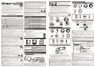
8 Troubleshooting<br />
Warning<br />
If any indication of the problem is found in the product, check to make sure<br />
the product will operate as expected. Failure to do so can lead to serious accidents.<br />
If any problem is found during using, setting or operating this product, use<br />
the following table to confirm proper operation of the unit. If the operational<br />
problem is not found in the following table, contact the installation<br />
personnel at the store where this product was purchased.<br />
Condition Possible Cause Corrective Action<br />
○ Does not operate. ○ Wiring of the power supply wire ○ Check wirings of +B, IGN,<br />
○ Power is not supplied.<br />
○ DC Source LED of<br />
the control unit<br />
doesn't light.<br />
is improper.<br />
○ The fuse of the power supply<br />
wire is blown out.<br />
○ The locks of the solderless connectors<br />
are not locked tightly.<br />
GND as per instructions in<br />
this manual.<br />
○ Check wiring and replace<br />
the fuse.<br />
○ Check the lock of the solderless<br />
connectors.<br />
○ DC Source LED of<br />
the control unit is<br />
blinking.<br />
○ There is a wire short circuit or<br />
disconnected wire somewhere.<br />
Maybe there is something<br />
wrong on gauge.<br />
○ Reconfirm the wiring and<br />
the gauge according to<br />
operation manual. If any<br />
defects are not found, please<br />
ask the shop for inspection.<br />
○ Warning LED on<br />
gauge is blinking<br />
○ There is a wire short circuit or<br />
disconnected wire somewhere<br />
on sensor or sensor wire. Maybe<br />
there is something wrong between<br />
gauge and control unit.<br />
○ Reconfirm the sensor and<br />
sensor wire according to<br />
operation manual. If any<br />
defects are not found, please<br />
ask the shop for inspection.<br />
74
Condition Possible Cause Corrective Action<br />
○ The illumination of<br />
CR gauges is not<br />
lighted. The illumination<br />
○ The ILM wiring is improper.<br />
○ The locks of the solderless connectors<br />
are not locked tightly.<br />
○ Check wirings of ILM as per<br />
instructions in this manual.<br />
○ Check the lock of the solder-<br />
of BF gauges ○ The illumination of gauge is set less connectors.<br />
is not darkened. to off (illumination cancel).<br />
○ The dimmer setting of ZD is<br />
AUTO and vehicle is in bright<br />
light.<br />
○ Release illumination cancel<br />
function as per instructions<br />
in this manual.<br />
○ Change the dimmer setting<br />
to MANUAL or move vehicle<br />
to a dark place.<br />
○ Does not carry out<br />
the ending mode.<br />
○ The battery wiring is improper. ○ Check wiring of +B as per<br />
instructions in this manual.<br />
○ Check the solderless connector<br />
of battery wiring.<br />
○ Ask the store for inspection.<br />
○ The needle pointer<br />
is not around right<br />
under 0 before<br />
starting installation<br />
with power off.<br />
○ The needle pointer moved in<br />
transit.<br />
○ It is the unique feature of<br />
stepping motor that the<br />
needle pointer may move<br />
when a slight impact is<br />
made to the gauge with<br />
electricity off. Check if the<br />
needle pointer goes back to<br />
around 0 when the ignition<br />
is turned from on to off. If<br />
it does not, please contact<br />
the store or our customer<br />
service center.<br />
75
Condition Possible Cause Corrective Action<br />
○ The RPM is not<br />
displayed correctly.<br />
○ Wiring of the tachometer signal<br />
is wrong.<br />
○ Setting of the number of cylinders<br />
is wrong.<br />
○ Check wiring as per instructions<br />
in this manual.<br />
○ Follow tachometer operation<br />
manual and wiring<br />
instruction for Speed &<br />
Tachometer signal wire to<br />
confirm the wiring.<br />
○ Check the number of cylinders<br />
as per instructions in<br />
this manual.<br />
○ This tachometer<br />
is reading slightly<br />
lower than the<br />
original tachometer.<br />
○ Generally tachometer readings<br />
are about up to 10 % higher<br />
than actual RPM.<br />
○ Check if the difference is<br />
up to 10% . This product is<br />
designed for high accuracy<br />
and should have little error<br />
margin. If the difference<br />
is much more than 10% ,<br />
check setting of the number<br />
of cylinders.<br />
○ Serial line error is<br />
displayed.<br />
○ Communication error is occurred<br />
between gauges/ZDs<br />
and the control unit.<br />
○ Check the meter wire as per<br />
instructions in this manual.<br />
If any defects are not found,<br />
please ask the shop for<br />
inspection.<br />
○ Serial line errors are<br />
displayed on all the<br />
connected gauges.<br />
○ More than one pressure<br />
sensors(turbo, oil pressure, and<br />
fuel pressure) short-circuit.<br />
○ In case that the sensor<br />
is broken, it need to be<br />
changed. please ask the<br />
shop for inspection.<br />
76
9 Repair parts/Optional parts<br />
AD:For <strong>ADVANCE</strong> system exclusive use<br />
Parts Number<br />
PDF07702H<br />
PDF07707H<br />
PDF07710H<br />
PDF07807G<br />
PDF08606G<br />
PDF07808G<br />
PDF07809G<br />
PDF07812G<br />
PDF08607 G<br />
PDF06503S<br />
PDF00703S<br />
PDF00903S<br />
PDF01103S<br />
PDF01105G<br />
PDF06505H<br />
PDF08105H<br />
PDF06603H<br />
PDF05602H<br />
PDF05603H<br />
PDF06803H<br />
PDF09705H<br />
PDF05005G<br />
Parts Number<br />
PDF07708H<br />
PDF07709H<br />
PDF06002H<br />
PDF06013H<br />
PDF00707H<br />
PDF06014H<br />
PDF00906H<br />
PDF01107H<br />
DF09601<br />
DF09501<br />
Repair Parts Name<br />
AD Power supply wire (1m, 3 1/3ft)<br />
AD Meter wire (0.25m, 10in)<br />
AD Meter wire (2m, 6 3/5ft)<br />
AD meter cup (52mm, 2 1/16in)<br />
AD meter cup (60mm, 2 3/8in)<br />
AD Buffer<br />
AD Installation parts for meter & ZD<br />
AD Regular Position Bezel (52mm, 2 1/16in)<br />
AD Regular Position Bezel (60mm, 2 3/8in)<br />
Turbo Sensor<br />
Pressure Sensor<br />
Temperature Sensor<br />
Exhaust Temp. Sensor<br />
Fitting for Exhaust Temp. Sensor<br />
Turbo Sensor wire (2.5m, 8 1/5ft)<br />
AD Oil Press. Sensor wire (3m, 10ft)<br />
Fuel Press. Sensor wire (2.5m, 8 1/5ft)<br />
Oil Temp. Sensor wire (3m, 10ft)<br />
Water Temp. Sensor wire (3m, 10ft)<br />
Exhaust Temp. Sensor wire (2.5m, 8 1/5ft)<br />
AD Speed & Tachometer signal wire (2m, 6 3/5ft)<br />
Fuse(4A)2pcs<br />
Optional Parts Name<br />
AD Meter wire(0.5m, 1 3/5ft)<br />
AD Meter wire(1m, 3 1/3ft)<br />
Turbo Sensor extension wire (1m, 3 1/3ft)<br />
Pressure Sensor extension wire (1m, 3 1/3ft)<br />
Pressure Sensor extension wire (2m, 6 3/5ft)<br />
Temperature Sensor extension wire (1m, 3 1/3ft)<br />
Temperature Sensor extension wire (2m, 6 3/5ft)<br />
Exhaust Temp. Sensor extension wire (2m, 6 3/5ft)<br />
<strong>ADVANCE</strong> Indicator<br />
Fitting kit<br />
※ For more information, contact our customer service center, or visit our website.<br />
77
Maintenance & Check/Warranty & Servicing<br />
■ Warranty card・Terms and conditions<br />
This product is delivered with this operation manual and a warranty card.<br />
Please read terms and conditions in this manual thoroughly and keep the warranty<br />
card in a safe place. Failure to show this warranty will void the warranty.<br />
■ Warranty period<br />
Limited one year warranty. The warranty period starts at the date of retail purchase<br />
by the original end-user purchase. Please confirm the warranty card is<br />
provided with the information of retail store where purchased. Please refer to<br />
Limited Warranty for details.<br />
Warning<br />
Except in the case of defects, we shall not be liable for any trouble including<br />
violation, accident or improper wiring resulting from using this product.<br />
The warranty does not cover any unauthorized repair performed or caused<br />
to be performed by the end user. Such action can destroy or damage this<br />
product.<br />
■ Inspection<br />
Please ask the shop you purchased the product for inspection if any defect in<br />
product is suspected. We don't accept the order of fixing because <strong>Defi</strong> products<br />
require installation and wiring to the vehicle.<br />
In case you cannot go to the shop you purchased because of move-out or closure<br />
of shop, please ask the nearest <strong>Defi</strong> Distributor listed in the <strong>Defi</strong> website.<br />
※ For a repair/inspection service, take the warranty card and customer contact<br />
information with you.<br />
78
Customer contact information<br />
Please provide the following information to a store representative when you ask for an inspection.<br />
1. Your contact information<br />
address, zip code:<br />
name:<br />
phone number:<br />
email address:<br />
2. Name and address of the store where purchased and installed.<br />
3. Information about your vehicle<br />
manufacture and car model:<br />
model year:<br />
vehicle type:<br />
engine type:<br />
engine displacement:<br />
transmission (MT/AT):<br />
speed limit canceller with without<br />
genuine tachometer with without<br />
engine swap with without<br />
changing ignition device with without<br />
changing ECU with without<br />
the way to install the sensor:<br />
other specification:<br />
4.Your <strong>Defi</strong> products<br />
(including the products that do not need inspection this time)<br />
5.Describe your experience<br />
(when? do what?, what product? what happened? then what?)<br />
79
■ Label<br />
The label sticked on the product is for the product traceability. Do not peel it<br />
off.<br />
■ Repairing<br />
When a repair is necessary, we will return the inspection result report through<br />
the store to you. After receiving a repair service request, we start repairing.<br />
Ask the store how much it costs and how long it takes to repair.<br />
■ Discarding the products<br />
Please dispose products in accordance with disposal laws, state laws and local<br />
government. A recycle label on the package indicates that the package is recyclable.<br />
80
Terms and Conditions<br />
LIMITED PRODUCT WARRANTY AND LIMITED PRODUCT LIABILITY<br />
A. Limited Warranty<br />
a. Our sole obligation to you after the sale of a product is to replace, without<br />
charge, the product or any component thereof discovered to be defective<br />
within a period of one (1) year from the purchasing date(the "Warranty<br />
Period"). You accept sole responsibility for the proper assembly operation<br />
and regular maintenance of the product. This limited warranty is void if any<br />
product is damaged by accident, misuse, improper installation, or abuse,<br />
including tampering or damage in transit. Further, this limited warranty is<br />
void if you sell or otherwise transfer a product to a third party, regardless of<br />
whether the transfer takes place within the Warranty Period.<br />
b. Out liability to you resulting from the sale of any product, including liability<br />
for any latent defects found within the Warranty Period, shall not exceed<br />
the total purchase price paid for the product by you.<br />
c. YOU UNDERSTAND AND AGREE THAT WE MAKE NO REPRESENTATIONS<br />
OR WARRANTIES OF ANY KIND, EXPRESS OR IMPLIED AS TO ANY MATTER<br />
WHATSOEVER, INCLUDING THE CONDITION OF THE PRODUCT OR ANY<br />
COMPONENT PARTS THEREOF, ITS MERCHANTABILITY OR ITS FITNESS FOR<br />
ANY PARTICULAR PURPOSE AND YOU ACCEPT IT, "AS IS," "WHERE IS."<br />
d. You also understand that we are not granting any express warranties, other<br />
than those stated herein. These include only those warranties enumerated<br />
in paragraph A. a. There are no other express warranties granted anywhere<br />
in these terms and conditions of sale, and you understand and agree to this<br />
fact as part of the bargained for exchange of this sale. Nowhere else, except<br />
as stated in this paragraph, in this contract is there intended, by either party,<br />
for there to be any express warranties granted to you.<br />
e. EXCEPT AS OTHERWISE PROVIDED HEREIN, WE SHALL NOT BE LIABLE FOR<br />
DAMAGES, INCLUDING SPECIAL, INCIDENTAL OR CONSEQUENTIAL DAM-<br />
AGES WHETHER IN CONTRACT OR IN TORT ARISING OUT OF OR IN CONNEC-<br />
TION WITH THE PERFORMANCE OF ANY PRODUCT OR ANY COMPONENT<br />
PART THEREOF OR ITS USE BY YOU, AND WE SHALL NOT BE LIABLE FOR ANY<br />
SPECIAL, INCIDENTAL OR CONSEQUENTIAL DAMAGES ARISING OUT OF OR<br />
81
IN CONNECTION WITH YOUR USE OF THE PRODUCT.<br />
f. The warranty on this product is void if the product is modified, changed,<br />
adjusted or damaged. This product is to be used only in the ways for which<br />
it is designed and marketed for, any deviations from the intended uses will<br />
void the warranty and will excuse any possible liability of ours.<br />
g. You accept sole responsibility for the proper assembly, operation and<br />
regular maintenance of the product. This limited warranty is void if the<br />
product is damaged, changed, altered, or modified by accident, misuse,<br />
improper installation , or abuse, including tampering or damage in transit<br />
or while in use. YOU HAVE MADE AN INDEPENDENT INVESTIGATION OF THE<br />
PURCHASED COMPONENTS AND HAVE RELIED SOLELY ON YOU OWN IN-<br />
VESTIGATION, BARGAINING AND JUDGMENT IN REFERENCE THERETO. YOU<br />
ACKNOWLEDGE THAT YOU ARE NOT RELYING ON OUR SKILL OR JUDGMENT<br />
TO SELECT OR FURNISH GOODS SUITABLE FOR ANY PARTICULAR PURPOSE<br />
IN PURCHASING OUR PRODUCTS, YOU HAVE NOT RELIED OR ACTED UPON<br />
ANY REPRESENTATIONS OR WARRANTIES ON OUR PART NOT SPECIFICALLY<br />
SET FORTH HEREIN.<br />
h. This limited warranty gives you specific legal rights. You may also have<br />
other rights which vary from state to state. Some states do not enforce contractual<br />
limitations on how long an implied warranty lasts, when an action<br />
may be brought, or the exclusion or limitation of incidental or consequential<br />
damages, so the above limitations or exclusions may not apply to you.<br />
B. Modification Strictly Prohibited<br />
You understand and agree that any modification whatsoever , of the product, is<br />
strictly prohibited. You also agree not to modify the product in any manner<br />
regardless of whether such modification is material or immaterial. You also acknowledge<br />
that any modification of the product will void your limited warranty<br />
and bar you from any recovery or any remedy in a court of law or equity. Modification<br />
is strictly forbidden unless expressly authorized by our prior written approval.<br />
You agree not to make any modifications to the product and agree not<br />
to use any parts, components, or accessories in connection with the installation<br />
and use of the product that are not authorized and approved by us.<br />
C. Indemnity and Release<br />
82
a. You understand and agree that many factors beyond our control affect the<br />
operational safety of the product, including but not to limited to the installation<br />
of the product according to the instructions provided with the product.<br />
b. You also understand and agree that the installation of the product may<br />
involve the use of tools, equipment and construction methods which may<br />
present safety hazards which are beyond our control. You also understand<br />
and agree that the use of some of our products may create hazards and<br />
lower your ability to control your vehicle.<br />
c. You agree, as part of the bargained for exchange, to protect, indemnify, save<br />
harmless and release us, our authorized agents, employees, officers, directors<br />
and shareholders from and against all liabilities, obligations, claims,<br />
damages, penalties, causes of action, costs and expenses, imposed upon or<br />
incurred by or asserted against us or any assignees of ours, by you or any<br />
third party by reason of the occurrence or existence (or alleged occurrence<br />
or existence) of any use, installation, assembly, possession or operation of<br />
the product, any loss, damage or destruction of the product as of and after<br />
delivery(a "casualty occurrence"), and any other act or event relating to or<br />
caused by the product, including but not limited to, consequential or of<br />
the terms and conditions hereof, or any and all liability for property loss or<br />
damage, or any and all damage resulting from death or personal injuries, including<br />
loss of services which any person may sustain on account of, arising<br />
out of, or in connection with any use, maintenance, possession or operation<br />
of the product. In the event that any action, suit or proceeding is brought<br />
against us or any of our authorized agents, employees, officers, directors or<br />
shareholders by reason of any such occurrence, you will, upon our request<br />
and at your expense, resist and defend such action, suit or proceeding or<br />
cause the same to be resisted and defended by counsel designated and approved<br />
by us.<br />
83
デフィーリンクアドバンス コントロールユニット 取 扱 説 明 書<br />
■ 発 行 初 版 2011 年 12 月<br />
■ 製 造 元 日 本 精 機 株 式 会 社<br />
■ 連 絡 先 日 本 精 機 株 式 会 社 Def i お 客 様 相 談 室<br />
【 住 所 】〒 940-2141 新 潟 県 長 岡 市 藤 橋 1-190-1 R&D センター <strong>Defi</strong><br />
【 電 話 番 号 】(03)3835-3639 (Japanese only)<br />
【FAX 番 号 】(03)3834-8116<br />
【 受 付 時 間 】10:00 ~ 12:00, 13:00 ~ 17:00( 土 ・ 日 曜 、 祭 日 、 当 社 休 日 を 除 く 平 日 )<br />
【Web サイト】http://www.nippon-seiki.co.jp/defi/<br />
Def i-Link <strong>ADVANCE</strong> <strong>Control</strong> <strong>Unit</strong> Operation <strong>Manual</strong><br />
■ Issue First edition: December, 2011<br />
■ Manufacturer Nippon Seiki Co., Ltd.<br />
■ Contact Information <strong>Defi</strong>, Nippon Seiki Co., Ltd.<br />
【Address】190-1 Fujihashi 1-chome, Nagaoka-shi, Niigata 940-2141 JAPAN<br />
【URL】http://www.defi-shop.com/<br />
PAT No.3019067 PAT No.3019939<br />
Made in Japan<br />
'11.12-1