Instruction Manual for EExde Motors - Rotor UK
Instruction Manual for EExde Motors - Rotor UK
Instruction Manual for EExde Motors - Rotor UK

Create successful ePaper yourself
Turn your PDF publications into a flip-book with our unique Google optimized e-Paper software.
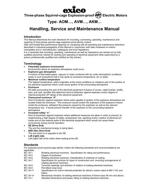
Three-phase Squirrel-cage Explosion-proof<br />
Type: AOM…, AVM…, AKM…<br />
Electric <strong>Motors</strong><br />
Handling, Service and Maintenance <strong>Manual</strong><br />
Introduction<br />
This <strong>Manual</strong> determines the main directions <strong>for</strong> mounting, connecting, operating, maintenance and<br />
repairing of three-phase squirrel-cage explosion-proof electric motors.<br />
Safe and trouble-free per<strong>for</strong>mance depends on complying with all operating and maintenance directions<br />
described in individual paragraphs of this <strong>Manual</strong> in conjunction with data contained on motors’<br />
nameplates and in manufacturers’ catalogues and local regulations.<br />
It is a necessity that mounting, operating, maintenance as well as inspections are carried out by fully<br />
qualified personnel, trained <strong>for</strong> working and operating of electrical equipment while supervised by a<br />
person professionally qualified and certified as fully trained.<br />
Terminology<br />
• Potentially explosive environment<br />
Environment where an explosive atmosphere could occur.<br />
• Explosive gas atmosphere<br />
A mixture of flammable gases, vapours or mists combined with air under atmospheric conditions<br />
exists in such proportions that it may ignite by excessive temperature, arc or spark.<br />
• Maximum surface temperature<br />
The highest temperature, which originates at the worst conditions on whatever part of the surface of<br />
the electrical equipment which could cause ignition of the surrounding atmosphere.<br />
• Enclosure<br />
All walls surrounding live part of the electrical equipment inclusive of covers, cable bushes, shafts,<br />
bars, pull rods, spindles that determine kind of protection against explosion and/or degree of<br />
internal protection (IP rating) of the electrical equipment.<br />
• Flame-proof enclosure “d”<br />
Kind of protection against explosion where parts capable of ignition of the explosive atmosphere are<br />
located inside the enclosure. This enclosure would contain the explosion of the explosive mixture<br />
inside the enclosure, withstand the pressure caused by the explosion as well as the relevant<br />
temperature rise. It would prevent transfer of the explosion to the surrounding explosive<br />
atmosphere.<br />
• Increased safety “e”<br />
Kind of prevention against explosion where additional measures are taken in order to prevent, by<br />
implementing a high degree of safety, temperature rise, sparking and/or creation of electrical arc<br />
inside and on the external parts of the electrical equipment which would not cause these<br />
occurrences during normal operation.<br />
• DE (Drive End)<br />
The end the mechanical energy is being taken.<br />
• NDE (Non Drive End)<br />
The end which is in opposite to the DE.<br />
• Left (right) side<br />
Left (right) half of the motor when looking at the DE.<br />
Standards<br />
For explosion-proof squirrel-cage electric motors the following standards and recommendations are<br />
applicable:<br />
IEC 34-1 Rotating electrical machines. Specification <strong>for</strong> rating and per<strong>for</strong>mance.<br />
IEC 34-5 Degree of protection<br />
IEC 34-6 Rotating electrical machines. Classification of methods of cooling.<br />
IEC 34-7 Specification <strong>for</strong> symbols <strong>for</strong> types of construction and mounting arrangements of<br />
rotating electrical machines.<br />
IEC 34-8 Terminal markings and direction of rotation of rotating electrical machines.<br />
IEC 34-9 Permitted noise level.<br />
IEC 34-11 Specification <strong>for</strong> built-in thermal protection <strong>for</strong> electric motors rated at 660 V AC and<br />
below.<br />
IEC 34-14 Mechanical vibration of rotating electrical machines of frame sizes 56 mm and above.<br />
IEC 72-1 Standard dimensions and power rating of rotating electrical machines.
IEC 38<br />
EN 50014<br />
EN 50018<br />
EN 50019<br />
Standardised voltages.<br />
Electrical apparatus <strong>for</strong> potentially explosive atmospheres. General requirements.<br />
Electrical apparatus <strong>for</strong> potentially explosive atmospheres. Flame–proof enclosure “d”.<br />
Electrical apparatus <strong>for</strong> potentially explosive atmospheres. Increased safety “e”.<br />
Marking of the electrical apparatus <strong>for</strong> potentially explosive<br />
atmospheres.<br />
The permitted utilisation of the electrical apparatus is determined by<br />
explosion proof execution described by its marking according to EN 50014.<br />
Explosion-proof marking is written on motor’s nameplate and on the<br />
relevant certificate and consists of the following marks:<br />
EEx<br />
defines that the apparatus complies with one or more kinds of protections against<br />
explosion specified in the EN 50014 standard.<br />
d<br />
designation of the protection against explosion, Flame-proof Enclosure<br />
e<br />
designation of the protection against explosion, Increased Safety<br />
IIB<br />
designation of the Group of the explosion-proof electrical apparatus<br />
H 2<br />
explosive gas of the Group IIC – Hydrogen<br />
T4<br />
Temperature Class designation of the explosion-proof electrical apparatus of Group II<br />
Complete designation of the explosion-proof electric motor<br />
<strong>EExde</strong> IIB+H 2T4<br />
Electrical apparatus <strong>for</strong> potentially explosive environment other than<br />
environment where methane is present, with protection against explosion<br />
applicable <strong>for</strong> the motor is Flame-proof Enclosure and its terminal box is of<br />
Increased Safety. Both are of Group IIB complemented with hydrogen H 2<br />
which normally falls in Group IIC and the Temperature Class T4.<br />
Execution<br />
If not agreed otherwise rated data <strong>for</strong> continuous Duty Cycle S1 are valid at frequency of 50Hz, ambient<br />
and/or coolant temperature up to +40°C and an altitude up to 1000 metres above see level.<br />
<strong>Motors</strong> of frame sizes 71 to 100 mm are of protection IP54 and frame sizes 112 to 200 mm are of<br />
protection IP55. Degree of protection of the fan is IP2.. Method of cooling is IC411.<br />
The motor itself is fully Flame –proof according to European Norm<br />
EN 50014 and EN 50018. The terminal box is of Increased Safety according to EN 50014 and EN<br />
50019.<br />
Design<br />
The explosion-proof motors are fully enclosed, fan ventilated three-phase squirrel-cage induction motors<br />
<strong>for</strong> low voltage application.<br />
The mounting arrangements available are specified in the relevant catalogue as well as in the mounting<br />
arrangement table enclosed with this document.<br />
The basic construction parts, the frame, both endshields, flanges, bearing retainer plates and caps as<br />
well as the terminal box are all of grey cast iron.<br />
The fan is of Al-Si alloy.<br />
Fans of motors of frame sizes 71 to 132 and 200 mm are fitted to the shaft with a key and a key way,<br />
fans of motors of frame sizes 160 and 180 are clamped to the shaft.<br />
The fan cover is of steel sheet per<strong>for</strong>ated 8 x 8 mm at the suction end.<br />
Terminal box is located on top and the cable entry can be turned at 90°.<br />
Terminal box is equipped with one, two or three explosion-proof cable glands on its side depending on<br />
the construction arrangement.<br />
<strong>Motors</strong> suitable <strong>for</strong> direct on-line starting are equipped with one cable gland as standard. <strong>Motors</strong><br />
suitable <strong>for</strong> Star-Delta starting are equipped with two explosion-proof cable glands.<br />
<strong>Motors</strong> which are equipped with temperature gauges of built-in thermal protection are always fitted with<br />
one extra auxiliary explosion-proof cable gland <strong>for</strong> cabling the temperature gauges to the thermal<br />
protection control system.<br />
Connection terminals are designed as explosion-proof bushes interconnecting the inside of the motor<br />
frame with the inside of the terminal box.<br />
For wiring of the motor it is possible to use copper cables as well as cables with aluminium conductors.<br />
Design of 132M foot mounted and foot & flange mounted motors enables its fitting to 132S fitting<br />
dimensions, similarly 160L and 180L foot and foot & flange motors could be fitted to 160M and 180M<br />
fitting dimensions respectively.<br />
The symmetrical position of the stator packs in the relevant frames enables all flange mounted motors to<br />
be turned through 180° when required in order to choose the position of the terminal box on the DE or<br />
NDE.<br />
Feet of foot and foot & flange mounted motors of frame sizes 71 to 180 mm are cast-on the frames<br />
whereas the feet of the 200 frame are bolted.<br />
DE shaft ends of all frame sizes are equipped with centralising tapped holes and keys with a key way.<br />
- 2 -
All rotors are dynamically balanced with full key, designation F.<br />
<strong>Motors</strong> frame sizes 71 to 100 mm are fitted with closed ball bearings, 62 range, lubricated <strong>for</strong> life.<br />
<strong>Motors</strong> frame sizes 112 to 200 are fitted with open ball bearings, 63 range as standard. At modified<br />
executions these frame sizes are fitted with closed bearings, lubricated <strong>for</strong> life.<br />
Detailed description of individual parts of motors can be found in later paragraphs of this manual.<br />
This description of the motor construction is valid <strong>for</strong> the basic standard execution and some other<br />
executions derived from the standard motors.<br />
The number of executions and their modifications is much larger. It is there<strong>for</strong>e not possible to describe<br />
them all in this brief description.<br />
Should you have any query please ask your national distributor or directly the manufacturer, Siemens<br />
Elektromotory, s.r.o., manufacturing plant Frenstat.<br />
Health and Safety <strong>Instruction</strong>s<br />
The electrical machines described in this manual make parts of industrial electrical equipment. They<br />
have been designed to relevant recognised technical standards.<br />
Due to their functional electrical and mechanical properties these machines may in certain<br />
circumtances, cause health or material hazard e.g. when misused, incompetently handled, when<br />
insufficiant maintenance is exercised or when subject of unacceptable manipulation.<br />
General criteria <strong>for</strong> permitted use which means fitting, mounting and operational conditions are<br />
determined by the data contained on the motor‘s nameplate, in the relevant catalogue and possibly in<br />
the technical conditions agreed between the customer and the manufacturer which must be strictly<br />
adhered to.<br />
In case of utilising the motor <strong>for</strong> a non-industrial application where some extra Health and Safety<br />
measures (e.g. Protection against electric shock) are required, it is necessary to guarantee that these<br />
additional safety measures are taken on the whole equipment at the time the motor is fitted.<br />
Only those measures necessary to be taken when installing in an industrial environment are described<br />
in the operation manual. When installing a motor national, local and other requirements and provisions<br />
specific <strong>for</strong> the equipment in question must be taken into consideration.<br />
It is supposed that when designing and implementing all mechanical and electrical instalations,<br />
transportation, fitting and commissioning, operation, maintenance and repairs will be carried out and<br />
supervised by qualified personnel suitably trained.<br />
This includes the implementation of general rules <strong>for</strong> fitting and safety working on electrical equipment<br />
as well as professional use of lifting equipment, binding equipment and tools.<br />
Transportation and storage<br />
Individual motors may be suspended only by their suspension eye bolts. The lifting capacity of the lifting<br />
gear must be chosen according to the weight of the motor marked on the nameplate.<br />
When installing a suitable guidance by rope or span beam must be used.<br />
The eye bolts must be well tightened be<strong>for</strong>e lifting. The eye bolts have been designed to withstand the<br />
weight of the motor only so they must not be used <strong>for</strong> lifting the whole assembly of the motor and the<br />
driven equipment.<br />
<strong>Motors</strong> suitable <strong>for</strong> vertical mounting are equipped with additional eye bolts which may only be used <strong>for</strong><br />
motor installation. Both bolts must be well tightened be<strong>for</strong>e lifting.<br />
Should some of the motors not be commissioned immediately after delivery they must be stored in a<br />
dry, vibration free storage place.<br />
During storage the motors must be protected against permanent moisture, dirt, dust and various<br />
chemical vapours and incompetent handling must be avoided. The storage place must be indoor, clean,<br />
dust-free and without vibrations (v ef ≤ 0.2 mm/s). The storage place must not be heated and maximum<br />
relative air humidity must not exceed 80% at 20°C.<br />
Installation<br />
When installing the motors in a potentially explosive environment all local and national standards and<br />
regulations must be complied with as well as all rules set by the relevant supervising authority.<br />
The kind of Protection against Explosion, explosion-proof equipment Group and Temperature Class is<br />
marked on the motor nameplate.<br />
When installing the motor all measures must be taken in order to prevent the motor being subject to<br />
harmful effects caused by other equipment such as heat radiation, vibration, etc. The terminal box lid,<br />
suction grill of the fan cover, lubricating nipples and motor nameplate must be fully accessible at all<br />
times.<br />
Uni<strong>for</strong>m cooling must be enabled to all surfaces, inclusive of the bottom of the motor, in order to prevent<br />
local excessive increase of the surface temperature.<br />
Cooling air must not be prevented from free inlet and free outlet <strong>for</strong> air-cooled motors. The dimension<br />
“x” (see the catalogue) must be kept in order to ensure the minimal gap between suction grill of the fan<br />
cover and neighbouring equipment. It is imperative that the hot outlet cooling air must not be re-used as<br />
an inlet air <strong>for</strong> cooling.<br />
Vertically mounted motors with the shaft down must be equipped with a canopy in order to prevent<br />
<strong>for</strong>eign bodies entering the fan compartment through the fan cover grill.<br />
- 3 -
Provision must be made <strong>for</strong> motors mounted in IM 3031 (IM V3) position to prevent flooding of the<br />
flange and the entering of <strong>for</strong>eign bodies between the ribs of the motor and its fan cover.<br />
<strong>Motors</strong> mounted in IM 3011 (IM V1) position have the terminal box located near NDE. It is<br />
recommended that the terminal box of these motors is turned <strong>for</strong> 90° so that the cable entry can be<br />
made from the free shaft end. Water running alongside the cable will not come in contact with the cable<br />
gland and terminal box side.<br />
<strong>Motors</strong> installed outdoors must be fitted with a protective shield as prevention against direct sun<br />
radiation in the summer and snow etc. in the winter. The protective shield must not effect motor cooling<br />
in any way.<br />
During adverse operational conditions high temperatures over 100°C might occur locally on the surface<br />
of the motor. Relevant provisions must prevent direct contact of personnel with these temperatures. No<br />
temperature sensitive parts such as cables, conductors and/or electronic devices must be laid onto or<br />
fitted to these surfaces.<br />
Fitting<br />
The motor must be fitted in the position that has been determined by the mounting marked on motor<br />
nameplate. Fitting in any other position must be consulted with the national distributor or the<br />
manufacturer.<br />
Mechanical connection with the driven equipment can be achieved through a flexible coupling or other<br />
transmission elements whilst ensuring that the permitted load of the shaft end (obtain from<br />
manufacturers’ catalogue or ask your national distributor) is not exceeded. Additionally <strong>for</strong> the correct<br />
mechanical connection provisions contained in the operation manual of the driven equipment must be<br />
taken into consideration.<br />
Measuring of deviations during the coupling adjustment is shown on Fig.1.<br />
Fig.1 Coupling adjustment<br />
Permitted deviations of the correct coupling adjustment are shown in the following table<br />
Permitted Fitting Deviations<br />
Coupling Size D<br />
[mm]<br />
Offset ∆x<br />
[µm]<br />
Angle Deviation ∆y<br />
[µm]<br />
125 70 200<br />
160 70 200<br />
200 and 250 80 220<br />
315 80 220<br />
355 and 400 90 250<br />
It is recommended to make precise adjustment of the coupling without utilising the maximum permitted<br />
deviations from the table above <strong>for</strong> smooth vibration-free and quiet operation and <strong>for</strong> utilising full life of<br />
the bearings.<br />
Belt and pulley transmission use is possible only when the relevant standards and provisions regarding<br />
the protection against dangerous effects of static electricity in the specific environment are kept.<br />
<strong>Rotor</strong>s are dynamically balanced with full key as standard and marking “F” could be found on the shaft<br />
front face or inside the key way.<br />
If required by the customer rotors could be dynamically balanced with half key. In this case “H” could be<br />
found on the shaft front face or inside the key way.<br />
All couplings or pulleys that are to be fitted to the motor shaft must be dynamically balanced. The<br />
balancing should be carried out without a key <strong>for</strong> motors dynamically balanced with full key (F).<br />
- 4 -
Should the rotor be dynamically balanced with half key (H), it is necessary to fit a coupling or pulley<br />
dynamically balanced with half key.<br />
It is necessary to clean the shaft end to remove the protective conservation layer and lubricate it with oil<br />
be<strong>for</strong>e fitting a coupling or pulley. It is recommended that all couplings, pulleys and other parts be<br />
heated be<strong>for</strong>e fitting on the shaft end.<br />
Should the fitting be carried out without heating of the part to be fitted it is recommended that a suitable<br />
tool is used.<br />
A suitable puller must be used <strong>for</strong> pulling the parts fitted on the shaft end and a provision must be made<br />
to prevent destruction of the tapped hole in the shaft end (see Fig.2).<br />
Insert <strong>for</strong> protection of the tapped hole<br />
Fig.2 Coupling fitting and removing (tapped hole protection)<br />
The motor must stand on a firm base and its feet on a plain metal surface. If necessary thin metal shims<br />
must be put under the feet to prevent pre-tension of the motor. The number of shims should be kept to<br />
the minimum.<br />
It is necessary to check the coupling adjustment after fitting and tightening the fixing screws.<br />
Stable mounting base, precise levelling of the motor, correct balancing of the parts fitted to the shaft end<br />
are all necessary measures <strong>for</strong> trouble-free quiet operation without vibration.<br />
No excessive <strong>for</strong>ce must be exercised when fitting and removing transmission parts.<br />
The keys are secured in the key way during transportation only.<br />
If the motor is double shafted and one of the shaft ends will not be used <strong>for</strong> connection with driven<br />
equipment it is necessary to remove the key be<strong>for</strong>e commissioning. Additional provisions <strong>for</strong> balancing<br />
must be made should the motor comply with additional requirements <strong>for</strong> reduced level of vibration.<br />
Provisions must be made to prevent access by personnel to the rotating parts of the motor, coupling,<br />
pulley and/or other transmission elements.<br />
Provision must be made (e.g. fitting a safety valve) <strong>for</strong> those applications where after disconnecting the<br />
motor due to a fault to prevent a situation where the driven equipment (e.g. a pump) could be driving the<br />
motor (due to reverse flow of the pumped fluid).<br />
Protection against electric shock<br />
Protection against electric shock of parts not normally under voltage must be carried out according to<br />
IEC 364, IEC 479 and IEC 536 as well as according to the valid national rules and standards. An earth<br />
conductor must be connected to the earth terminal of the motor designated by Mark 5019 according to<br />
IEC 417. There are two earth terminals on the motors, one on the outside frame and the other is inside<br />
the terminal box. With regards to the danger of electrocution it is necessary to pay the relevant attention<br />
to all kinds of possible protection against electric shock of all parts not normally under voltage.<br />
Wiring up<br />
The motor must be wired according to the wiring diagram located in the inside of the terminal box lid. It<br />
must be ensured that all inlet conductors make good contact with the motor terminals and that this<br />
contact will be permanent. The voltage marked on the motor nameplate and connection of the motor<br />
terminals must con<strong>for</strong>m to the voltage of the supplying mains.<br />
The size of the inlet cable must be chosen according to the rated current of the motor as well as<br />
conditions depending on the whole equipment, environmental temperature, the way the conductor is laid<br />
down, length of the conductor, etc.<br />
It is possible to carry out the wiring termination utilising the terminals the explosion proof bushes are<br />
equipped with where no cable eyes are required.<br />
The terminal marking used is to IEC 34-8. If multiple bushes are used the terminals are marked by<br />
numbers and on the wiring diagram located inside of the terminal box lid. It is clearly marked which<br />
- 5 -
number is assigned <strong>for</strong> which terminal marking as per IEC 34-8. The same marking is also stamped on<br />
the terminal box bottom.<br />
Terminals are marked as U, V, W <strong>for</strong> motors designed <strong>for</strong> direct on-line starting.<br />
If connecting the mains with the sequence of phases L1, L2, L3 to terminals U, V, W the motor will<br />
operate in a clockwise direction of rotation. In order to change the direction of rotation it is necessary to<br />
swap any of the two inlet phases. All motors have been designed to run in both directions of rotation.<br />
The way of wiring up of the motors, winding configurations and built-in thermal protection are described<br />
in other paragraphs of this manual.<br />
<strong>Motors</strong> with temperature gauges must be wired to the thermal protection control system in a way that<br />
prevents an automatic start-up of the motor after the temperature has cooled down and the temperature<br />
gauges have connected back up in order to eliminate a non-expected start-up of the driven equipment.<br />
The start-up should be carried out in full awareness of the operation by the operation personnel.<br />
Be<strong>for</strong>e the terminal lid is fitted back on the following must be checked:<br />
• inlet conductors and possibly the links in the terminal box must comply with the wiring diagram<br />
located in the terminal box lid as well as with the voltage of the supplying mains.<br />
• the inside of the terminal box must be clean and free from cable offcuts and/or other <strong>for</strong>eign objects.<br />
• all nuts on all studs of the bushes are fully tightened inclusive of any auxiliary terminals the motor<br />
may be equipped with but not employed <strong>for</strong> the application<br />
• the minimum air distances between live parts must be kept (8 mm <strong>for</strong> ≤ 500V, 10 mm <strong>for</strong> ≤ 690V, 14<br />
mm <strong>for</strong> 1kV). No wires from a stranded conductor must stick out.<br />
• inlet conductors must be laid down without any mechanical tension and their insulation must not be<br />
damaged.<br />
• the cable glands not used are fully closed and lifting elements are well tightened (a tool must be<br />
utilised <strong>for</strong> their release)<br />
• in order to comply with the marked degree of protection all seals and sealed surfaces must not be<br />
damaged or de<strong>for</strong>med. If the slot tightness itself is secured by the precision of the contacting metal<br />
surfaces it is necessary to clean them and lubricate them with a silicon grease after any<br />
manipulation with them.<br />
• cable glands and blinds to be correctly chosen and fitted with regards to the required protection<br />
against explosion, the way the cable is laid down, diameter of the cable used, etc.<br />
• cable glands and blinds to be tightened correctly<br />
After wiring up the motor the terminal box lid must carefully fitted and screws tightened.<br />
Circuit braking and over-current protection<br />
The motor must be protected against overloading and short circuit according to the relevant standards.<br />
The system of protection measures must be correctly chosen and the protection elements must be<br />
correctly set to the rated current marked on the motor nameplate.<br />
During operation an overloading might occur that could defect or destroy the motor winding and cause<br />
inadequate surface temperature rise. It is there<strong>for</strong>e necessary to protect the motor by circuit breakers<br />
and fuses.<br />
Fuses should be chosen to be <strong>for</strong> 60% to 100% higher current than the rated current of the motor. They<br />
protect the motor and the cabling against short circuit. It is there<strong>for</strong>e necessary to use a circuit breaker<br />
with current characteristics, which protects the motor against overloading. In case of higher short-circuit<br />
capacity of the supplying mains it is necessary to fit fuses be<strong>for</strong>e the circuit breakers. It is permitted to<br />
use similar types of protection depending on the current of all three phases.<br />
<strong>Motors</strong> <strong>for</strong> rated voltages according to IEC 38 are marked with a range of rated voltages and the<br />
greatest rated current valid <strong>for</strong> the whole range of voltages marked on the motor nameplate. Deviations<br />
<strong>for</strong> environment A according to IEC 34-1 are valid <strong>for</strong> these values.<br />
Temperature gauges, built in thermal protection<br />
<strong>Motors</strong> may be equipped with temperature gauges, PTC thermistors built-in in the critical part of the<br />
stator winding. The temperature gauges are located in each phase of the stator are connected in series<br />
and terminated to auxiliary terminals of the explosion-proof bushing marked as T1 and T2. They are to<br />
be connected to the thermal protection control system. Temperature gauges allow temperature<br />
sensitive detection of the thermal protection connected to the control system. The type of the thermal<br />
protection is TP111 according to IEC 34-11.<br />
This thermal protection is effective when the motor is subject to insufficient cooling causing thermal<br />
overloading as well as excessive increase of the coolant temperature, gradual mechanical overloading<br />
or long-term drop or increase of the supplying voltage. When the critical temperature rise has been<br />
reached the built-in thermal protection in conjunction with its control system disconnects the motor from<br />
the supply.<br />
The built-in thermal protection is a simple but effective complement of the over-current protection under<br />
those fault conditions where the over-current protection is not able to protect the motor at all times.<br />
The relevant wiring diagram and its connection is described under paragraph Terminal Box Assembly.<br />
During operation it is possible to check the functionality of the thermal protection by establishing the<br />
continuity of the thermistor circuit by measuring the resistance of the circuit while the control system is<br />
- 6 -
disconnected. At the temperature gauge temperature 25°C ± 5°C the resistance of the thermal<br />
protection circuit must not be greater than 800Ω.<br />
It is possible to carry out the resistance measuring by standard measuring instruments but the voltage<br />
applied to thermistor circuit must not exceed 4.5V. All relevant rules applicable <strong>for</strong> the environment in<br />
question must be complied with during measuring.<br />
It is necessary to connect the thermal protection to its control system by a separate cable to avoid<br />
voltage induction to the thermal protection circuit from the supplying power cable. The Thermal<br />
Protection Connection Diagram can be seen bellow (Fig.14).<br />
Supply <strong>for</strong> motors through frequency inverters must be always operated with fully functional built-in<br />
thermal protection.<br />
The thermal protection control system must be certified by a recognised certification body <strong>for</strong> use with<br />
explosion-proof electric motors.<br />
Fig.14 Thermal Protection Connection Diagram<br />
Insulation test<br />
Be<strong>for</strong>e commissioning after long term storage or after putting out of operation the insulation resistance<br />
of the winding must be checked. The insulation resistance of the motor winding is measured with DC<br />
voltage against the frame. This must be also carried out during inspection.<br />
The limit value of the smallest insulation resistance, critical insulation resistance and measuring voltages<br />
<strong>for</strong> motors with rated voltage up to<br />
1000 V must comply with the following.<br />
• New, cleaned or repaired winding R i ≥ 10 MΩ U zDC = 500V<br />
• Critical insulation resistance after 0.5 MΩ/kV U zDC = 500V<br />
some time of operation<br />
The above data are applicable <strong>for</strong> measuring at an ambient temperature of 25°C.<br />
New dry windings have their insulation resistance higher than the limit insulation resistance. If the value<br />
of the insulation resistance is close to the smallest limit value, the cause of this occurrence may be<br />
humidity or pollution. If the value is lower it is necessary to establish the cause of the occurrence. It<br />
may be that the winding needs drying.<br />
The insulation resistance of the clean winding is directly dependent on temperature. It drops to half its<br />
value when the temperature has risen <strong>for</strong> 10K. This means that if the temperature has risen <strong>for</strong> 50K the<br />
insulation resistance drops to 1/32 of the initial value.<br />
During the time of operation the insulation resistance can decrease due to the environment and<br />
operational influence.<br />
The critical value of the insulation resistance at the temperature of 25°C is possible to calculate from the<br />
rated voltage multiplied by specific value of the critical insulation resistance.<br />
For example the critical insulation resistance <strong>for</strong> voltage 690 V is:<br />
0.69 kV x 0.5MΩ/kV = 0.345 MΩ<br />
If during operation the value of the insulation resistance is higher than the value of the calculated critical<br />
insulation resistance the motor is possible to use further.<br />
If, however, the insulation value is close to the calculated critical value it is necessary to dry the winding<br />
and possibly dismantle the motor, clean the stator and dry it out.<br />
If the insulation value is close to the critical value it is necessary to ensure that the insulation resistance<br />
checks are carried out in short intervals.<br />
Measuring of the insulation resistance of low voltage motors is carried out by using measuring<br />
instruments with voltage 500 V. Subsequent measuring by instruments with voltage 1000 V is permitted<br />
only when the result of the measuring with 500 V was found to be higher than the critical insulation<br />
resistance.<br />
- 7 -
Drying of the motor winding can be carried out by brought up heat (in drying ovens) or by heat<br />
generated inside the motor when a DC current is applied. When drying by DC current its value must not<br />
exceed 50% to 70% of the AC rated current of the relevant winding. It is recommended that the<br />
individual windings are connected in a way that uni<strong>for</strong>m load to each phase is applied. It is<br />
recommended to increase the DC current gradually and if the motor seems to be more damp then the<br />
increase of the DC current must be slower.<br />
When drying in an oven the temperature of the air must not exceed 90°C. If the motor seems to be<br />
more damp the increase of the drying air temperature must be slower.<br />
It is necessary to measure the winding temperature and check the insulation resistance when drying.<br />
Commissioning of the motor<br />
Preparation<br />
It is necessary to check the following after fitting or inspection:<br />
• The fitting and operational conditions comply with the data specified on the motor nameplate<br />
(voltage, current, connection, mounting, explosion-proof rating, degree of protection, method of<br />
cooling, etc.).<br />
• The motor is properly fitted and levelled.<br />
• The driving elements, according to their design, must be correctly set and adjusted (tension of the<br />
belts of a belt drive, teeth clearance and top clearance of toothed wheel drive, coupling adjustment,<br />
etc.).<br />
• The minimum permitted insulation resistance must be complied with (valid also after longer<br />
operational break).<br />
• The machine has been connected in a way that the required direction of rotation has been ensured.<br />
• The rotor of the motor could be rotated by hand.<br />
• All fitting screws and bolts must be fully tightened as well as all nuts of the terminal studs.<br />
• All earth wiring has been properly connected as well as the cables <strong>for</strong> equalising the electric<br />
potential where required.<br />
• Bearings have been lubricated as described in this manual.<br />
• The built-in thermal protection must be connected to its control system and its functionality must be<br />
checked.<br />
• All relevant provisions of protection against electric shock applicable <strong>for</strong> moving parts as well as <strong>for</strong><br />
live parts must be carried out.<br />
These basic provisions is necessary to complement by additional measures where required (<strong>for</strong> special<br />
executions or additional safety requirements).<br />
Starting<br />
Additionally to the normal commissioning the following provisions are recommended after fitting or<br />
inspection:<br />
• Motor is to be started without load.<br />
• The noise level and level of vibrations is to be assessed in set main points.<br />
• Should the motor not run smoothly or if the noise level is too high the motor must be disconnected<br />
and assessed during the run-out.<br />
• If mechanical running is improved purely by disconnecting the supply the possible cause of the<br />
problem could be found in the electromagnetic part of the motor. If, however, the run does not<br />
improve after disconnecting, the problem will be in mechanical arrangement such as imbalance of<br />
the motor or the driven equipment, insufficient equilising of the system of the machines, etc.<br />
• If the motor is running smoothly it is possible to put it under load. It is necessary to check the<br />
smooth run under load, measure the voltage, the current and the output which should be endorsed<br />
in a Commissioning Report.<br />
• The temperature of bearings, winding, etc should be checked until a stable condition is reached and<br />
endorsed in a Commissioning Report.<br />
Switching off<br />
Disconnect the power supply and let the motor run-out without braking. Do not open the motor terminal<br />
box lid until stationary and disconnected from the power supply and control system.<br />
Operation<br />
Do not open any cover protecting live or rotating parts or any cover necessary <strong>for</strong> correct guidance of<br />
the cooling air to ensure that the maximum cooling effect is reached during operation.<br />
It is possible to assess the motor functionality according to the changes of the motor operation<br />
compared with correct normal operation. It is necessary that immediate fault assessment and<br />
subsequent rectification of the problem found is carried out in order to prevent major damage.<br />
It is supposed that switching on and off is carried out by means of automatic control.<br />
If the equipment is not in operation <strong>for</strong> a long period of time regular checks must be carried out to<br />
maintain the motor dryness and the motor must be run on a regular basis (approximately once a month)<br />
or at minimum the rotor must be rotated by hand.<br />
- 8 -
In case of a long term break in operation the provisions described under Commissioning must be carried<br />
out.<br />
Maintenance<br />
Professionally trained and fully qualified personnel can maintain explosion-proof motors.<br />
It must be ensured that the power supply is disconnected and isolated according to the local provisions<br />
be<strong>for</strong>e commencement of any work on the explosion-proof motor, especially be<strong>for</strong>e opening any active<br />
parts cover.<br />
As well as the power supply all additional, auxiliary and protective circuits must be disconnected be<strong>for</strong>e<br />
commencement of any work.<br />
The basic safety rules:<br />
• Switch the power off.<br />
• Prevent repeated switching on.<br />
• Make sure that there is no power anywhere in the motor.<br />
• Make sure that the motor and the driven equipment are earthed.<br />
• Cover or mark off all the neighbouring active parts.<br />
Inspections, checks and overhauls<br />
The thorough and regular maintenance, inspections and checks are necessary measures in order to<br />
identify and rectify all possible faults in time be<strong>for</strong>e they develop into major damage.<br />
It is possible to recommend just general intervals due to the different operational conditions of individual<br />
motors.<br />
The maintenance intervals must be established based on various conditions such as dust settlement,<br />
frequency of starting, kind of load, etc.<br />
The recommended time intervals are based on the assumption of trouble-free operation.<br />
It is necessary to carry out relevant checks, or even inspection, if faults or extraordinary conditions such<br />
as electrical or mechanical overloading or short circuiting occur.<br />
As far as bearing lubrication is concerned see paragraph Bearings and Lubrication.<br />
It is necessary to clean the motor surface as well as any air inlets on a regular basis <strong>for</strong> example by dry<br />
compressed air. The cleaning interval depends on the degree of soiling.<br />
A provision <strong>for</strong> air extraction should be made when cleaning by compressed air. Some protective items<br />
such as glasses, respirator, etc. must be worn.<br />
The first inspection<br />
It is recommended to carry out the first general inspection after approximately 500 hours of operation to<br />
establish that:<br />
• all required technical conditions of the operation are complied with (inlet power, bearing<br />
temperature, winding temperature, coolant temperature, etc.)<br />
• no loose fittings can be found<br />
• the motor operation is smooth with no excessive noise or vibrations<br />
• motor fitting is not impaired<br />
All deviations found during checks or inspections as well as all changes must be immediately rectified.<br />
Overhauling<br />
It is possible to carry out overhauling at the same time as maintenance, such as lubrication or grease<br />
replacement, is carried out on low voltage motors.<br />
It is necessary to check the following:<br />
• rectification tolerance of the rotor<br />
• that all fixing screws and bolts as well as nuts on the terminal studs are tightened<br />
• insulation resistance of the winding is at a sufficient level<br />
• cables, conductors, insulation parts and explosion-proof glands are in good condition without any<br />
discoloration.<br />
During general overhauling it is not normally necessary to disassemble the motor. This is normally<br />
carried out only when changing bearings.<br />
Dismantling and mounting of the terminal box, motors, bearings as well as directions <strong>for</strong> lubrication or<br />
bearing replacement are described in the later paragraphs of this manual.<br />
Repairs and alterations<br />
All repairs and alterations which could influence a protection against explosion is necessary to be<br />
carried out at the manufacturers or at a manufacturer approved repair shop.<br />
Repaired motors and their technical details must fully comply to the approved documentation. Be<strong>for</strong>e<br />
any alteration is carried out it is necessary to establish whether such an alteration is permitted whether<br />
the final altered execution is one of the approved executions or whether it is necessary to re-certify the<br />
motor to include the required execution. In order to do that the consent of the manufacturer has to be<br />
sought.<br />
- 9 -
If a major alteration without certification is carried out or if any detail which is part of the protection<br />
against explosion is altered by non-authorised repair shop the certification declared on the motor<br />
nameplate is considered to be void.<br />
Altered motors must be fitted with new nameplates where the relevant repair shop logo is clearly<br />
displayed. The motors must be then certified by a recognised certification body authorised to certify<br />
explosion-proof apparatus.<br />
Replacement of fans, bearings, cable glands, part of the terminals or terminal box mounting near DE or<br />
NDE etc. are classified as alterations which do not effect protection against explosion if carried out by<br />
qualified personnel.<br />
Terminal board assembly and its connection<br />
The terminal board type OEM 100 to 200 has been designed as increased safety “e” (type of explosionproof<br />
protection) according to EN 50014 and EN 50019 and is of protection IP55 according to IEC 34-5.<br />
The terminal board of explosion proof motors suitable <strong>for</strong> direct on-line starting is equipped by three<br />
main terminals marked U, V, W. <strong>Motors</strong> suitable <strong>for</strong> Star/Delta starting or motors suitable <strong>for</strong> dual<br />
voltage are equipped with six main terminals marked as U1, V1, W1, U2, V2, W2.<br />
Some special executions may be equipped with additional auxiliary terminals <strong>for</strong> thermal protection.<br />
The following tables show what types of terminal boards are assigned <strong>for</strong> which motor as well as the<br />
difference between standard and special executions of explosion-proof motors.<br />
Motor<br />
Size<br />
Terminal<br />
Box Type<br />
Starting and<br />
Number of<br />
Terminals<br />
Size of Main Terminals<br />
- 10 -<br />
Terminals<br />
<strong>for</strong> Thermal<br />
Protection<br />
Earth Terminals<br />
Max<br />
Cross-section<br />
of Conductors<br />
Standard Special Standard Special Internal External Standard Special<br />
71<br />
80<br />
90 OEM 100 M5 M4 or M7x0.75 M4 or M7x0.75 M5 10 6<br />
100<br />
112 DOL/3 Y-∆/6 2xM5<br />
132 OEM 112 M5 M5 2xM5 10<br />
160 OEM 160 2xM5 2xM5 25 25<br />
180 OEM 180 M4 or M5<br />
200 OEM 200 2xM6 2xM6 35 35<br />
Motor<br />
Size<br />
Terminal<br />
Box Type<br />
Terminal<br />
Box<br />
Location<br />
Explosion-proof<br />
rating/<br />
Degree of<br />
Terminal<br />
Box<br />
Turning<br />
Number and Size<br />
of Cable Glands<br />
Max Diameter of the<br />
Cable (mm)<br />
Protection Standard Special S‘d Special<br />
71<br />
80 PG16 2xPG13.5 or PG13.5 & PG16 14 2x12 or 14&12<br />
90 OEM 100<br />
100<br />
112 Top EExeII / IP55 90° & 180° PG21 2xPG16 or PG21& PG13.5 18 2x14 or 18&12<br />
132 OEM 112<br />
160 OEM 160<br />
180 OEM 180 PG29 2xPG29 or 2xPG29& PG13.5 25 2x25 or 2x25&12<br />
200 OEM 200 PG36 2xPG36 or 2xPG36& PG13.5 32 2x32 or 2x32&12<br />
All necessary in<strong>for</strong>mation about possible terminal board executions available can be found in the<br />
manufacturers’ catalogue. For further details please contact your national distributor.<br />
<strong>Motors</strong> of frame sizes 71 to 132 with built-in thermal protection are delivered suitable <strong>for</strong> direct on-line<br />
starting only.<br />
For motors of frame sizes 71 to 100 with built-in thermal protection a multiple explosion-proof bushing is<br />
used.<br />
It is necessary to connect the power cables and the auxiliary circuits according to the wiring diagram<br />
located in the terminal box lid.<br />
<strong>Motors</strong> frame sizes 160 to 200 with built-in thermal protection are suitable <strong>for</strong> Direct-on-line starting and<br />
a modified execution suitable <strong>for</strong> Star-Delta starting or Y/∆ connection could be delivered.<br />
The connecting terminals are part of the explosion-proof bushings. The relevant design of the<br />
explosion-proof bushings can be seen on installation drawings and diagrams.
The basic power explosion-proof terminal rating in relation to motor sizes as well as the torque<br />
necessary <strong>for</strong> tightening of the nut/stud assembly is shown in the following table:<br />
Motor Size Explosion-proof<br />
Bushing Type<br />
Stud Size Tightening<br />
Torque [Nm]<br />
Cable Clamp<br />
Screw Size<br />
Cable Clamp Screw<br />
Tightening Torque<br />
71 to 132 25.1 M5 2.5 -- --<br />
160 63.2 M6 4 2 x M5 4<br />
180, 200 100.2 M8 8 2 x M6 5<br />
The M4 bolts grade 8.8 used <strong>for</strong> clamping the bar cable clamp on the bushing stud are necessary to be<br />
tightened using a torque of 3Nm after possible repositioning.<br />
The explosion-proof bushing type 25.1 is used also <strong>for</strong> connection of the protection current circuits.<br />
Different types of bushings can be also used <strong>for</strong> this application.<br />
Terminal board assembly options and their arrangements can be found on the drawing shown in the<br />
following table.<br />
Terminal box assembly Terminal box drawing Connection drawing<br />
OEM 100 Fig.3 Fig.4<br />
OEM 112 Fig.5 Fig.6 & Fig.7<br />
OEM 160 Fig.5 Fig 9 & Fig 10<br />
OEM 180 & OEM 200 Fig.8 Fig 9 & Fig 10<br />
Fig.3 OEM 100 Terminal Box<br />
Fig.5 OEM 112 & OEM 160 Terminal Box<br />
Fig.4 OEM 100 Terminal Box - Connection<br />
Fig.6 OEM 112 Terminal Box – Connection Delta<br />
- 11 -
Fig.7 OEM 112 Terminal Box - Connection Star Fig.9 OEM 112, OEM 180, OEM 200<br />
Terminal Box - Connection Delta<br />
Fig.8 OEM 180, OEM 200 Terminal Box<br />
Fig.9 OEM 112, OEM 180, OEM 200<br />
Terminal Box - Connection Star<br />
- 12 -
Bearings and bearing assembly<br />
<strong>Motors</strong> frame sizes 71 to 100 mm are equipped with closed radial ball size 62 bearings lubricated <strong>for</strong><br />
life. Bearing chambers in the endshields are half filled with lithium based lubrication grease. The<br />
chambers are protected from outside by a flame-proof enclosure slot between the endshield and the<br />
shaft.<br />
<strong>Motors</strong> frame sizes 112 and 132 are equipped with open size 63 bearings without provision <strong>for</strong><br />
lubrication.<br />
<strong>Motors</strong> frame sizes 160 to 200 are equipped with open size 63 bearings with lubrication canal and<br />
nipples.<br />
Modified executions of motors frame sizes 112 and 132 can be delivered with closed bearings lubricated<br />
<strong>for</strong> life.<br />
Bearing chambers in the endshields are half filled with lithium based lubrication grease. The chambers<br />
are protected from the inside by a flame-proof enclosure slot between the enshield and the shaft and by<br />
a radial oil seal from outside.<br />
For noise and vibration suppression and <strong>for</strong> bearing protection against excessive vibration the bearings<br />
are axially pre-loaded by wavy washers.<br />
Types of wavy washers can be found in the table below.<br />
The relevant design of the bearing assembly <strong>for</strong> each individual size of motors can be seen on the<br />
drawings in the motor handbook.<br />
All motor sizes have axially fixed bearings on the NDE.<br />
When installing a motor and fitting transmission elements the thermal dilatation of the shaft end during<br />
the motor operation must be taken into consideration in order to avoid a creation of excessive axial<br />
pressure on the bearings and their subsequent failure.<br />
Bearing rating, radial oil seal rating and wavy washer rating in relation to motor sizes is shown in the<br />
following table.<br />
Motor Size DE and NDE Bearing Radial Oil Seal Axial Wavy Washer<br />
[drawing No., type]<br />
71 6203 2Z C3 5 065 651<br />
80 6204 2Z C3 5 065 515<br />
90 6205 2Z C3 5 065 475<br />
100 6206 2Z C3 5 065 476<br />
112 6306 C3 G30 x 47 x 7 5 065 493<br />
132 6308 C3 G40 x 52 x 7 5 065 519<br />
160 6309 C3 G45 x 65 x 8 EMO – X67<br />
180 6310 C3 G50 x 72 x 8 EMO – X72<br />
200 6312 C3 G60 x 90 x 8 EMO – X86<br />
The maximum permitted temperature of the bearings is 100°C.<br />
Lubrication, replacement of grease<br />
<strong>Motors</strong> frame sizes 71 to 100 are equipped with closed bearings lubricated <strong>for</strong> life. These bearings are<br />
fully lubricated <strong>for</strong> several years. In order to decide to replace a bearing a bearing assessment based<br />
on diagnostic testing and temperature measurement must be carried out.<br />
After dismantling the motor endshield in the case where the bearing need not to be replaced the<br />
endshield chamber must be cleaned and again half filled with new grease.<br />
For motors frame sizes 112 and 132 with open bearings where motor speed does not exceed 1800 rpm<br />
the grease replacement and re-lubrication is carried out after 20,000 hours of operation or after 3 years<br />
from installation, whichever is earlier, operating conditions permitting. Should the motor speed exceed<br />
1800 rpm then the re-lubrication period is shortened to 10,000 hours of operation or 1½ years from<br />
installation, whichever is earlier, operating conditions permitting.<br />
The above indicated periods of time are valid under normal operational conditions.<br />
Should the motor be subject to severe operational conditions such as high environmental temperature,<br />
excessive vibrations, aggressive or corrosive environment etc. it is necessary to shorten the relubrication<br />
period to suit.<br />
The re-lubrication intervals <strong>for</strong> bearings lubricated by lithium based grease <strong>for</strong> motors frame sizes 160 to<br />
200 under normal operational conditions are shown in the following table.<br />
Motor Size Bearing Re-lubrication Interval T [hours]<br />
Type 2 pole 4 pole 6 pole 8 pole<br />
160 6000 12000 12000 12000<br />
180 ball 3000 6000 12000 12000<br />
200 3000 6000 12000 12000<br />
At severe operational conditions it is necessary to shorten the re-lubrication period to suit. See the<br />
lubrication grease manufacturer’s recommendation.<br />
- 13 -
Motor Dismantling<br />
When dismantling a motor the following sequence of operation must be taken:<br />
• remove the key from the key way from DE shaft (28)<br />
• unscrew the lubrication nipple (21) (<strong>for</strong> frame sizes 160 to 200)<br />
• unscrew fan cover fixing screws (70) and remove them together with the spring washers<br />
• remove the fan cover (25)<br />
• remove the circlip (37) (<strong>for</strong> frame sizes 71 to 132 and 200) or loosen the clamping arrangement<br />
(frame sizes160 and 180) of the fan<br />
• remove the fan (24)<br />
• remove the fan key (38)<br />
• unscrew the fixing screws (73) (together with the spring washers) of the bearing cap (2) on DE.<br />
• remove the external bearing cap (2) on DE (frame sizes 122 to 200)<br />
• remove axial wavy washers (29)<br />
• unscrew and remove the fixing screws (74) (together with the spring washers) of the endshield (3)<br />
on DE<br />
• remove the DE endshield (3) inclusive of the bearing (5) (frame sizes 112 to 200)<br />
• unscrew the fixing screws (71) of the endshield (22) (together with the spring washers) on NDE.<br />
• remove the NDE endshield (22) inclusive of the complete rotor<br />
• protect the winding end against damage when dismantling<br />
Bearing assembly dismantling on NDE (frame sizes 71 to 100)<br />
• release the internal circlip (75) and remove it from the endshield housing<br />
• remove the endshield (22) from the bearing (19)<br />
• release and remove the shaft circlip (27)<br />
• pull-off the bearings (19) from the shaft (1)<br />
• dismantling of the NDE bearing is not required unless the bearing needs changing<br />
Bearing assembly dismantling on NDE (frame sizes 112 to 200)<br />
• release the fixing screws (72) (together with the spring washers) of the external bearing cap (23)<br />
• remove the external bearing cap (23)<br />
• release the shaft circlip (27)<br />
• pull-off the endshield (22) with the bearing (19) from the shaft (1)<br />
• push the bearing (19) from the endshield (22)<br />
• dismantling of the NDE bearing is not required unless the bearing needs changing<br />
Motor assembling<br />
The sequence of operation when assembling an electric motor is reciprocal to the dismantling procedure<br />
but the following provisions must be adhered to:<br />
• an electric motor assembly must be carried out in a clean environment<br />
• suitable tools and fitting fixtures must be used <strong>for</strong> radial oil seal fitting<br />
• the principles mentioned under Bearings and bearing assembly must be adhered to when<br />
assembling bearings<br />
• it is recommended to replace the DE bearing with the same type<br />
• it is advisable to carry out the assembly of the NDE bearing after removal from the stator<br />
• it is necessary to observe the correct oil seal orientation during assembly<br />
• cleanliness of all internal parts of the motor must be maintained at all times (prevent ingress of<br />
impurities, use clean connecting material)<br />
• bearing internal ring must be heated using an induction heater to reach a temperature of 80°C (max<br />
100°C) be<strong>for</strong>e fitting<br />
• all screws, nuts and bolts must be properly tightened using recommended torque<br />
• lithium based lubrication grease must be used, lubrication canals in endshields must be filled with<br />
grease be<strong>for</strong>e assembly<br />
• provisions described in the individual paragraphs of this <strong>Instruction</strong> <strong>Manual</strong> must be adhered to<br />
- 14 -
List of parts<br />
1 Shaft<br />
2 DE external bearing cap<br />
3 DE endshield<br />
5 DE bearing<br />
7 Terminal box lid<br />
9 Terminal box<br />
11 Internal earth terminal<br />
12 External earth terminal<br />
15 Stator pack (without winding)<br />
16 Frame<br />
17 <strong>Rotor</strong> pack with squirrel cage<br />
18 Stator winding<br />
19 NDE bearings<br />
21 Lubrication nipple<br />
22 NDE endshield<br />
23 NDE external bearing cap<br />
24 Fan<br />
25 Fan cover<br />
27 NDE bearing shaft circlip<br />
28 Shaft end key<br />
29 Wavy washer<br />
34 Terminal box bottom wall<br />
35 Bushing<br />
37 Fan circlip<br />
38 Fan key<br />
46 DE oil seal<br />
53 Terminal box lid gasket<br />
61 NDE oil seal<br />
75 NDE bearing endshield circlip<br />
Fig.11<br />
AOM71 - AOM100<br />
- 15 -
Fig.12 AOM112 - AOM160<br />
Fig.13 AOM180 & AOM200<br />
- 16 -
MOTOR MOUNTING ARRANGEMENT TABLE<br />
- 17 -