Manual Safe Lock - Troax-marketing.com
Manual Safe Lock - Troax-marketing.com
Manual Safe Lock - Troax-marketing.com

You also want an ePaper? Increase the reach of your titles
YUMPU automatically turns print PDFs into web optimized ePapers that Google loves.
<strong>Manual</strong><br />
<strong>Safe</strong> <strong>Lock</strong><br />
Gunnebo <strong>Troax</strong> AB, Box 89, SE-330 33 Hillerstorp, SWEDEN<br />
Telephone: +46 (0)370-828 00, Fax: +46 (0)370- 824 86, E-mail: info@troax.se<br />
www.troax.<strong>com</strong>
<strong>Safe</strong> <strong>Lock</strong> manual<br />
Table of Contents<br />
1 Manufacturer's declaration .............................................................................................<br />
3<br />
2 Introduction .....................................................................................................................<br />
4<br />
2.1 Scope ..............................................................................................................................<br />
4<br />
2.2 Audience .........................................................................................................................<br />
4<br />
2.3 Prerequisites ...................................................................................................................<br />
4<br />
2.4 Special Notes................................<br />
..................................................................................................................<br />
4<br />
3 Overview .........................................................................................................................<br />
5<br />
3.1 <strong>Safe</strong>ty Instructions ................................................................................................<br />
6<br />
4 Unpacking .......................................................................................................................<br />
7<br />
4.1 General Unpacking ................................................................................................<br />
7<br />
5 Installation .......................................................................................................................<br />
8<br />
5.1 After Installation ................................................................................................<br />
13<br />
6 Operation ......................................................................................................................<br />
14<br />
6.1 <strong>Lock</strong>ing .........................................................................................................................<br />
14<br />
6.2 Unlocking ......................................................................................................................<br />
14<br />
6.3 Emergency Exit ................................................................................................<br />
14<br />
7 Preventive Maintenance ...............................................................................................<br />
15<br />
7.1 Damp Atmosphere ................................................................................................<br />
16<br />
7.2 Dusty Atmosphere ................................................................................................<br />
16<br />
Appendix Documentation regarding safety switch from switch manufacturer.<br />
Copyright<br />
Copyright © 2005 Gunnebo <strong>Troax</strong> AB. All rights reserved.<br />
This document contains proprietary information that is protected by copyright. No part of this document<br />
may be reproduced or transmitted in any form or by any means, electronic or mechanical, including<br />
photocopying, recording, or by any information storage retrieval rieval system, or translated into another<br />
language, without prior written consent of Gunnebo <strong>Troax</strong> AB. The information in this document is<br />
subject to change without notice.<br />
<strong>Troax</strong> makes no warranty of any kind with regard to this material, including, but not limited to, the<br />
implied warranties of merchantability and fitness for a particular purpose. <strong>Troax</strong> shall not be liable for<br />
errors contained herein nor for incidental or consequential damages in connection with the furnishing,<br />
performance or use of this material.<br />
2<br />
<strong>Safe</strong> <strong>Lock</strong> manual, Revision 5<br />
September 2010
<strong>Safe</strong> <strong>Lock</strong> manual<br />
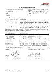
1 Manufacturer's declaration<br />
<strong>Safe</strong> <strong>Lock</strong> manual, Revision 5<br />
September 2010<br />
3
<strong>Safe</strong> <strong>Lock</strong> manual<br />
2 Introduction<br />
2.1 Scope<br />
2.2 Audience<br />
The purpose of this installation guide is to describe the 3 and 4-states <strong>Safe</strong> <strong>Lock</strong> (a<br />
description of the difference between 3 and 4-states <strong>Safe</strong> <strong>Lock</strong> in on page 5) to provide the<br />
necessary information for installation, checks after installation, adjustments, operation, and<br />
preventive maintenance. NOTE! This installation guide describes the mechanical installation<br />
of <strong>Safe</strong> <strong>Lock</strong>. For installation information of safety switches and the connection between the<br />
switches and the overall security/safety system, see the included documentation from the<br />
safety switch manufacturer.<br />
This document is written for authorized installation personnel.<br />
2.3 Prerequisites<br />
In this document, it is assumed that the reader has:<br />
• basic knowledge of Gunnebo <strong>Troax</strong> AB products<br />
• knowledge of safety switches<br />
• knowledge of machine safety<br />
2.4 Special Notes<br />
Pay attention to the special notes in the installation guide.<br />
Caution!<br />
NOTE!<br />
Warning!<br />
Danger of severe personal injury!<br />
An instruction or procedure which, if not carried out<br />
correctly, may result in injury to the technician or other<br />
personnel.<br />
Danger of damage to the equipment!<br />
An instruction or procedure which, if not carried out<br />
correctly, may damage the equipment.<br />
Notes are used to provide important or explanatory<br />
information.<br />
4<br />
<strong>Safe</strong> <strong>Lock</strong> manual, Revision 5<br />
September 2010
<strong>Safe</strong> <strong>Lock</strong> manual<br />
3 Overview<br />
<strong>Safe</strong> <strong>Lock</strong> is a security product equipped with a safety switch to prevent entrance to a<br />
machine installation when the machine is still running.<br />
NOTE! The safety switch <strong>com</strong>es in many different versions. This documentation does not<br />
describe your specific switch. For information about your switch, see the included<br />
documentation from the safety switch manufacturer.<br />
This installation guide describes the 3 and 4-states <strong>Safe</strong> <strong>Lock</strong>. The difference between the<br />
two is described below. NOTE! This is the Gunnebo <strong>Troax</strong> way of describing 3 and 4-states<br />
<strong>Safe</strong> <strong>Lock</strong>.<br />
Figure 1 Difference between 3 and 4-states <strong>Safe</strong> <strong>Lock</strong>. View from above.<br />
State 1<br />
State 2<br />
State 3<br />
Door open. Lever in position unlocked.<br />
Door closed. Lever in position unlocked.<br />
Door closed. Lever in position locked and closing is detected by the safety switch.<br />
Unlocking the door from inside or the outside will automatically stop the<br />
machinery. The unlocking of the door is “unconditional”.<br />
<strong>Safe</strong> <strong>Lock</strong> manual, Revision 5<br />
September 2010<br />
5
<strong>Safe</strong> <strong>Lock</strong> manual<br />
State 4<br />
Door closed. Lever in position locked and closing is detected by the safety switch.<br />
Solenoid in the switch holds key and prevents opening.<br />
The door can only be unlocked after <strong>com</strong>pletion of an external action, such as the<br />
end of the machine sequence, or once a machine’s momentum has been<br />
dissipated. The unlocking of the door is conditional.<br />
3.1 <strong>Safe</strong>ty Instructions<br />
Caution! It is important that you read the safety instructions (below) before installing the<br />
<strong>Safe</strong> <strong>Lock</strong>. Follow all instructions carefully to avoid personal injury or damage to the <strong>Safe</strong><br />
<strong>Lock</strong>.<br />
To prevent the <strong>Safe</strong> <strong>Lock</strong> from being tampered with, the lock must be fixed with blind rivets<br />
and the switch and key fastened with security screws (one-way screws or Torx screws with<br />
pins).<br />
To work safely in the machine installation, block the <strong>Safe</strong> <strong>Lock</strong> with a padlock. The padlock<br />
prevents the door from being closed and locked by someone else. There can be up to three<br />
different persons inside the machine installation at the same time. Each person has his/her<br />
own padlock. NOTE! The padlock is not included in the delivery.<br />
1<br />
2<br />
3<br />
4<br />
6<br />
5<br />
Figure 2 <strong>Safe</strong> <strong>Lock</strong> Overview<br />
1 Switch bracket<br />
2 Handle to open and close<br />
3 <strong>Safe</strong> <strong>Lock</strong> main unit<br />
4 Padlock bracket<br />
5 Emergency lever to open only<br />
6 <strong>Safe</strong>ty switch<br />
6<br />
<strong>Safe</strong> <strong>Lock</strong> manual, Revision 5<br />
September 2010
<strong>Safe</strong> <strong>Lock</strong> manual<br />
4 Unpacking<br />
The <strong>Safe</strong> <strong>Lock</strong> is delivered from the factory in one package with the <strong>Safe</strong> <strong>Lock</strong> main unit and<br />
the switch bracket separately packaged inside.<br />
4.1 General Unpacking<br />
When unpacking the delivered package, check that the contents match the packing list<br />
delivered with the package.<br />
The package should contain:<br />
• <strong>Safe</strong> <strong>Lock</strong> main unit<br />
• switch bracket with switch<br />
• plastic bag with fixing <strong>com</strong>ponents<br />
NOTE! Not all fixing <strong>com</strong>ponents in the bag will be used for the installation.<br />
Inspect every detail for transport damage. If damaged, please notify your sales<br />
representative or Gunnebo <strong>Troax</strong> subsidiary immediately.<br />
<strong>Safe</strong> <strong>Lock</strong> manual, Revision 5<br />
September 2010<br />
7
<strong>Safe</strong> <strong>Lock</strong> manual<br />
5 Installation<br />
In some cases, installation is <strong>com</strong>pleted at Gunnebo <strong>Troax</strong> AB. If so, please go to page 12<br />
for adjustment information.<br />
If the <strong>Safe</strong> <strong>Lock</strong> is not pre-installed, follow the instructions below to install the <strong>Safe</strong> <strong>Lock</strong>.<br />
1. Prepare holes according to the figure below (if not already prepared).<br />
Figure 3 <strong>Safe</strong> <strong>Lock</strong> hole dimensions<br />
8<br />
<strong>Safe</strong> <strong>Lock</strong> manual, Revision 5<br />
September 2010
<strong>Safe</strong> <strong>Lock</strong> manual<br />
2. Install the <strong>Safe</strong> <strong>Lock</strong>. Use the fixing <strong>com</strong>ponents from the plastic bag.<br />
1<br />
2<br />
3<br />
4<br />
Start with<br />
this screw<br />
Figure 4 Installation on door, 3-states <strong>Safe</strong> <strong>Lock</strong><br />
5<br />
Position<br />
1<br />
Figure Description Quantity Part number<br />
Washer 3 89050350<br />
2<br />
Spacer 2 89040114<br />
3<br />
4<br />
Washer 5 89050266<br />
Screw, MC6Sx16 4 89050025<br />
5<br />
Screw, M6Sx20 1 89050005<br />
<strong>Safe</strong> <strong>Lock</strong> manual, Revision 5<br />
September 2010<br />
9
<strong>Safe</strong> <strong>Lock</strong> manual<br />
1<br />
3<br />
2<br />
Start with<br />
this screw<br />
4<br />
Figure 5 Installation on door, 4-states <strong>Safe</strong> <strong>Lock</strong><br />
Position Figure Description Quantity Part number<br />
1 Washer 5 89050350<br />
2 Washer 5 89050266<br />
3 Screw, MC6Sx16 4 89050025<br />
4 Screw, M6Sx20 1 89050005<br />
10<br />
<strong>Safe</strong> <strong>Lock</strong> manual, Revision 5<br />
September 2010
<strong>Safe</strong> <strong>Lock</strong> manual<br />
For swing doors (with some types of switches), the hook must be removed. You are not able<br />
to close the door otherwise. You must remove the hook when you have the following<br />
switches:<br />
• SICK i17-SA213<br />
• GuardMaster Trojan 5<br />
• Schmersal AZ16<br />
3. Use a Torx wrench (see 1 in the figure below) to remove the screw that holds the hook.<br />
1<br />
Figure 6 Remove hook<br />
1 Torx wrench (not included in the delivery)<br />
<strong>Safe</strong> <strong>Lock</strong> manual, Revision 5<br />
September 2010<br />
11
<strong>Safe</strong> <strong>Lock</strong> manual<br />
4. Adjust the vertical position (5) by adjusting the screws on the switch bracket (1).<br />
5. Adjust the horizontal position (6) by adjusting the screws on the <strong>Safe</strong> <strong>Lock</strong> main unit (2).<br />
6. Adjust the depth (7) by adjusting the screws on the switch (4) and rod (3) guide located<br />
on the switch bracket (1).<br />
1<br />
2<br />
3<br />
5<br />
6<br />
4<br />
7<br />
Figure 7 Adjustment of the <strong>Safe</strong> <strong>Lock</strong> Unit<br />
1 Switch bracket<br />
2 <strong>Safe</strong> <strong>Lock</strong> main unit<br />
3 Rod guide<br />
4 <strong>Safe</strong>ty switch<br />
12<br />
<strong>Safe</strong> <strong>Lock</strong> manual, Revision 5<br />
September 2010
<strong>Safe</strong> <strong>Lock</strong> manual<br />
5.1 After Installation<br />
When the installation is <strong>com</strong>plete, and before first use, do the following:<br />
1. Check that all parts are assembled correctly.<br />
2. Check that all screws are tightened. Especially that the screw in the end of the<br />
emergency lever is tightened.<br />
3. Check that the emergency lever on the back of the <strong>Safe</strong> <strong>Lock</strong> unlocks the <strong>Safe</strong> <strong>Lock</strong>.<br />
4. Check that the key enters the switch without scraping. If not, adjust the switch position.<br />
Go to page 12 for adjustment information.<br />
5. Check that the key enters the switch far enough to close the circuit. If not, adjust this by<br />
moving the <strong>Safe</strong> <strong>Lock</strong> main unit towards the switch. Go to page 12 for adjustment<br />
information.<br />
Caution! It is, in no case, allowed to use the safety switch as a mechanical stop.<br />
NOTE! For switches with four fastening holes, use the one-way screw (see 2 in the figure<br />
below) to make a tamper-resistant installation. tion. For switches with two fastening holes, the<br />
switch is assembled with tamper-resistant screws when delivered.<br />
6. To prevent the <strong>Safe</strong> <strong>Lock</strong> from being tampered with, install the three blind rivets (see 1 in<br />
the figure below).<br />
W Warning!<br />
The blind rivets are used to secure and <strong>com</strong>plete the installation. If the blind rivets are not<br />
installed, there might be danger of severe personal injury and damage to the equipment.<br />
Figure 8 After installation<br />
<strong>Safe</strong> <strong>Lock</strong> manual, Revision 5<br />
September 2010<br />
13
<strong>Safe</strong> <strong>Lock</strong> manual<br />
6 Operation<br />
6.1 <strong>Lock</strong>ing<br />
1. Close the door.<br />
2. Unlock and remove the padlock, if one is fitted.<br />
3. Pull the handle to lock the <strong>Safe</strong> <strong>Lock</strong>.<br />
6.2 Unlocking<br />
1. Release the switch key (only applicable for a 4-states <strong>Safe</strong> <strong>Lock</strong>, please follow the switch<br />
instructions delivered from the safety switch manufacturer).<br />
2. Pull the handle to unlock the <strong>Safe</strong> <strong>Lock</strong>.<br />
3. Open the door.<br />
4. If you are going to work inside the machine installation, always make sure that the <strong>Safe</strong><br />
<strong>Lock</strong> is blocked with a padlock.<br />
6.3 Emergency Exit<br />
1. Push the red emergency stop button (only applicable for 4-states <strong>Safe</strong> <strong>Lock</strong>).<br />
2. Press the red emergency lever downwards to unlock the <strong>Safe</strong> <strong>Lock</strong>.<br />
3. Open the door.<br />
NOTE! The <strong>Safe</strong> <strong>Lock</strong> must not be locked from the inside.<br />
14<br />
<strong>Safe</strong> <strong>Lock</strong> manual, Revision 5<br />
September 2010
<strong>Safe</strong> <strong>Lock</strong> manual<br />
7 Preventive Maintenance<br />
This chapter describes the preventive maintenance needed for the <strong>Safe</strong> <strong>Lock</strong>. It is important<br />
that maintenance is carried out properly and regularly to ensure functionality.<br />
1. Tighten the screws to ensure best performance.<br />
2. Wipe off dust from the <strong>Safe</strong> <strong>Lock</strong>, the guide rod, and the switch and key in particular.<br />
3. Check regularly (at least once every work period) that the emergency lever on the back of<br />
the <strong>Safe</strong> <strong>Lock</strong> unlocks the <strong>Safe</strong> <strong>Lock</strong>.<br />
4. If the emergency lever “stands” vertically (as shown in the figure below), something is<br />
wrong with the <strong>Safe</strong> <strong>Lock</strong>. If the lever stands vertically, please contact your sales<br />
representative or Gunnebo <strong>Troax</strong> subsidiary immediately.<br />
Figure 9 Emergency lever in vertical position<br />
<strong>Safe</strong> <strong>Lock</strong> manual, Revision 5<br />
September 2010<br />
15
<strong>Safe</strong> <strong>Lock</strong> manual<br />
7.1 Damp Atmosphere<br />
<strong>Troax</strong> re<strong>com</strong>mends that you lubricate the <strong>Safe</strong> <strong>Lock</strong> (marked with “Lubricate here” in the<br />
figure below) with petrolatum at least once a month. You must not use a high pressure jet of<br />
water on the <strong>Safe</strong> <strong>Lock</strong>.<br />
Lubricate<br />
here<br />
Lubricate<br />
here<br />
Figure 10 Lubrication of <strong>Safe</strong> <strong>Lock</strong><br />
7.2 Dusty Atmosphere<br />
A dusty atmosphere also includes atmospheres with oil and grease.<br />
Preventive maintenance must be carried out at least once a month.<br />
Print number 201009-0243-SE<br />
16<br />
<strong>Safe</strong> <strong>Lock</strong> manual, Revision 5<br />
September 2010