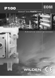
P800/PX800 - Process Pumps
P800/PX800 - Process Pumps
P800/PX800 - Process Pumps

You also want an ePaper? Increase the reach of your titles
YUMPU automatically turns print PDFs into web optimized ePapers that Google loves.
<strong>P800</strong>/<strong>PX800</strong><br />
Advanced Series METAL <strong>Pumps</strong><br />
Engineering<br />
Operation &<br />
Maintenance<br />
Advance your process<br />
WIL-11220-E-06<br />
REPLACES WIL-11220-E-05
TABLE OF CONTENTS<br />
SECTION 1 CAUTIONS—READ FIRST! . . . . . . . . . . . . . . . . . . . . . . . . . . . . . . . . . . . . . . . . . . . . . .1<br />
SECTION 2 WILDEN PUMP DESIGNATION SYSTEM . . . . . . . . . . . . . . . . . . . . . . . . . . . . . . . . .2<br />
SECTION 3 HOW IT WORKS—PUMP & AIR DISTRIBUTION SYSTEM . . . . . . . . . . . . . . . .3<br />
SECTION 4 DIMENSIONAL DRAWINGS . . . . . . . . . . . . . . . . . . . . . . . . . . . . . . . . . . . . . . . . . . . . .4<br />
SECTION 5 PERFORMANCE<br />
A. <strong>P800</strong> Performance Curves<br />
Rubber-Fitted . . . . . . . . . . . . . . . . . . . . . . . . . . . . . . . . . . . . . . . . . . . . . . . . . . . . . . . .6<br />
TPE-Fitted . . . . . . . . . . . . . . . . . . . . . . . . . . . . . . . . . . . . . . . . . . . . . . . . . . . . . . . . . . .6<br />
PTFE-Fitted . . . . . . . . . . . . . . . . . . . . . . . . . . . . . . . . . . . . . . . . . . . . . . . . . . . . . . . . . .7<br />
Ultra-Flex-Fitted . . . . . . . . . . . . . . . . . . . . . . . . . . . . . . . . . . . . . . . . . . . . . . . . . . . .7<br />
Suction Lift Curves . . . . . . . . . . . . . . . . . . . . . . . . . . . . . . . . . . . . . . . . . . . . . . . . . . .8<br />
B. <strong>PX800</strong> Performance<br />
Operating Principal . . . . . . . . . . . . . . . . . . . . . . . . . . . . . . . . . . . . . . . . . . . . . . . . . . 10<br />
How to Use this EMS Curve . . . . . . . . . . . . . . . . . . . . . . . . . . . . . . . . . . . . . . . . . . . 11<br />
Performance Curves<br />
Rubber-Fitted . . . . . . . . . . . . . . . . . . . . . . . . . . . . . . . . . . . . . . . . . . . . . . . . . . . .14<br />
TPE-Fitted . . . . . . . . . . . . . . . . . . . . . . . . . . . . . . . . . . . . . . . . . . . . . . . . . . . . . . .15<br />
PTFE-Fitted . . . . . . . . . . . . . . . . . . . . . . . . . . . . . . . . . . . . . . . . . . . . . . . . . . . . . .16<br />
Ultra-Flex-Fitted . . . . . . . . . . . . . . . . . . . . . . . . . . . . . . . . . . . . . . . . . . . . . . . .17<br />
Suction Lift Curves . . . . . . . . . . . . . . . . . . . . . . . . . . . . . . . . . . . . . . . . . . . . . . . . . .18<br />
SECTION 6 SUGGESTED INSTALLATION, OPERATION & TROUBLESHOOTING . . . . . . . 19<br />
SECTION 7 ASSEMBLY / DISASSEMBLY . . . . . . . . . . . . . . . . . . . . . . . . . . . . . . . . . . . . . . . . . . .22<br />
SECTION 8 EXPLODED VIEW & PARTS LISTING<br />
<strong>P800</strong> Aluminum<br />
Rubber/TPE/PTFE/Ultra-Flex-Fitted . . . . . . . . . . . . . . . . . . . . . . . . . . . . . . . . . . . .30<br />
<strong>P800</strong> Stainless Steel<br />
Rubber/TPE/PTFE/Ultra-Flex-Fitted . . . . . . . . . . . . . . . . . . . . . . . . . . . . . . . . . . . .32<br />
<strong>PX800</strong> Aluminum<br />
Rubber/TPE/PTFE/Ultra-Flex-Fitted . . . . . . . . . . . . . . . . . . . . . . . . . . . . . . . . . . . .34<br />
<strong>PX800</strong> Stainless Steel<br />
Rubber/TPE/PTFE/Ultra-Flex-Fitted . . . . . . . . . . . . . . . . . . . . . . . . . . . . . . . . . . . .36<br />
SECTION 9 ELASTOMER OPTIONS . . . . . . . . . . . . . . . . . . . . . . . . . . . . . . . . . . . . . . . . . . . . . . . . .38
Section 1<br />
CAUTIONS—READ FIRST!<br />
.<br />
CAUTION: Do not apply compressed air to the exhaust<br />
port — pump will not function.<br />
CAUTION: Do not, under any circumstance loosen the set<br />
screw located at the adjuster dial of the Pro-Flo X pump.<br />
If the set screw is loose when the pump is pressurized, it<br />
could eject and cause injury to anyone in the area.<br />
CAUTION: Do not over-lubricate air supply — excess<br />
lubrication will reduce pump performance. Pump is prelubed.<br />
TEMPERATURE LIMITS:<br />
Neoprene –17.7°C to 93.3°C 0°F to 200°F<br />
Buna-N –12.2°C to 82.2°C 10°F to 180°F<br />
Nordel ® –51.1°C to 137.8°C –60°F to 280°F<br />
Viton ® –40°C to 176.7°C –40°F to 350°F<br />
Saniflex –28.9°C to 104.4°C –20°F to 220°F<br />
Polytetrafluoroethylene (PTFE)<br />
4.4°C to 104.4°C 40°F to 220°F<br />
Polyurethane –12.2°C to 65.6°C 10°F to 150°F<br />
Tetra-Flex PTFE w/Neoprene Backed<br />
4.4°C to 107.2°C 40°F to 225°F<br />
Tetra-Flex PTFE w/Nordel ® Backed<br />
-10°C to 137°C 14°F to 280°F<br />
NOTE: Not all materials are available for all models.<br />
Refer to Section 2 for material options for your<br />
pump.<br />
CAUTION: When choosing pump materials, be sure to<br />
check the temperature limits for all wetted components.<br />
Example: Viton ® has a maximum limit of 176.7°C (350°F) but<br />
polypropylene has a maximum limit of only 79°C (175°F).<br />
CAUTION: Maximum temperature limits are based upon<br />
mechanical stress only. Certain chemicals will significantly<br />
reduce maximum safe operating temperatures. Consult<br />
Chemical Resistance Guide (E4) for chemical compatibility<br />
and temperature limits.<br />
WARNING: Prevention of static sparking — If static<br />
sparking occurs, fire or explosion could result. Pump,<br />
valves, and containers must be grounded to a proper<br />
grounding point when handling flammable fluids and<br />
whenever discharge of static electricity is a hazard.<br />
CAUTION: Do not exceed 8.6 bar (125 psig) air supply<br />
pressure.<br />
CAUTION: The process fluid and cleaning fluids must be<br />
chemically compatible with all wetted pump components.<br />
Consult Chemical Resistance Guide (E4).<br />
CAUTION: Do not exceed 82°C (180°F) air inlet temperature<br />
for Pro-Flo X models.<br />
CAUTION: <strong>Pumps</strong> should be thoroughly flushed before<br />
installing into process lines. FDA and USDA approved<br />
pumps should be cleaned and/or sanitized before being<br />
used.<br />
CAUTION: Always wear safety glasses when operating<br />
pump. If diaphragm rupture occurs, material being pumped<br />
may be forced out air exhaust.<br />
CAUTION: Before any maintenance or repair is attempted,<br />
the compressed air line to the pump should be disconnected<br />
and all air pressure allowed to bleed from pump. Disconnect<br />
all intake, discharge and air lines. Drain the pump by turning<br />
it upside down and allowing any fluid to flow into a suitable<br />
container.<br />
CAUTION: Blow out air line for 10 to 20 seconds before<br />
attaching to pump to make sure all pipeline debris is<br />
clear. Use an in-line air filter. A 5µ (micron) air filter is<br />
recommended.<br />
NOTE: When installing Teflon ® diaphragms, it is important<br />
to tighten outer pistons simultaneously (turning in opposite<br />
directions) to ensure tight fit. (See torque specifications in<br />
Section 7.)<br />
NOTE: Cast Iron Teflon ® -fitted pumps come standard<br />
from the factory with expanded Teflon ® gaskets installed<br />
in the diaphragm bead of the liquid chamber. Teflon ®<br />
gaskets cannot be re-used. Consult PS-TG for installation<br />
instructions during reassembly.<br />
NOTE: Before starting disassembly, mark a line from each<br />
liquid chamber to its corresponding air chamber. This line<br />
will assist in proper alignment during reassembly.<br />
CAUTION: Pro-Flo ® pumps cannot be used in submersible<br />
applications. Pro-Flo X is available in both submersible<br />
and non-submersible options. Do not use non-submersible<br />
Pro-Flo X models in submersible applications. Turbo-Flo ®<br />
pumps can also be used in submersible applications.<br />
CAUTION: Tighten all hardware prior to installation.<br />
WIL-11220-E-06 1 WILDEN PUMP & ENGINEERING, LLC
Section 2<br />
WILDEN PUMP DESIGNATION SYSTEM<br />
<strong>P800</strong>/<strong>PX800</strong> METAL<br />
51 mm (2") Pump<br />
Maximum Flow Rate:<br />
674 lpm (178 gpm)<br />
LEGEND<br />
<strong>P800</strong> / XXXXX / XXX / XX / XXX / XXXX<br />
MODEL<br />
O-RINGS<br />
VALVE SEAT<br />
VALVE BALLS<br />
DIAPHRAGMS<br />
AIR VALVE<br />
CENTER BLOCK<br />
AIR CHAMBERS<br />
WETTED PARTS & OUTER PISTON<br />
SPECIALTY<br />
CODE<br />
(if applicable)<br />
MATERIAL CODES<br />
MODEL<br />
<strong>P800</strong> = PRO-FLO ®<br />
<strong>PX800</strong> = PRO-FLO X<br />
WETTED PARTS & OUTER PISTON<br />
AA = ALUMINUM / ALUMINUM<br />
HH = ALLOY C / ALLOY C<br />
SS = STAINLESS STEEL /<br />
STAINLESS STEEL<br />
AIR CHAMBERS<br />
A = ALUMINUM<br />
C = TEFLON ® COATED<br />
N = NICKEL-PLATED<br />
S = STAINLESS STEEL<br />
V = HALAR ® COATED<br />
ALUMINUM (<strong>P800</strong> only)<br />
CENTER BLOCK<br />
A = ALUMINUM(<strong>PX800</strong> only)<br />
N = NICKEL-PLATED<br />
(<strong>PX800</strong> only)<br />
P = POLYPROPYLENE<br />
(<strong>P800</strong> only)<br />
S = STAINLESS STEEL<br />
(<strong>PX800</strong> only)<br />
AIR VALVE<br />
A = ALUMINUM (<strong>PX800</strong> only)<br />
N = NICKEL-PLATED<br />
(<strong>PX800</strong> only)<br />
P = POLYPROPYLENE<br />
(<strong>P800</strong> only)<br />
S = STAINLESS STEEL<br />
(<strong>PX800</strong> only)<br />
DIAPHRAGMS<br />
XBS = CONDUCTIVE BUNA-N<br />
(Two Red Dots)<br />
BNS = BUNA-N (Red Dot)<br />
FSS = SANIFLEX<br />
[Hytrel ® (Cream)]<br />
EPS = EPDM (Blue Dot)<br />
NES = NEOPRENE (Green Dot)<br />
PUS = POLYURETHANE (Clear)<br />
TEU = PTFE W/EPDM<br />
BACK-UP (White)<br />
TNU = PTFE W/NEOPRENE<br />
BACK-UP (White)<br />
TSU = PTFE W/SANIFLEX<br />
BACK-UP (White)<br />
BNU = BUNA-N, ULTRA-FLEX<br />
EPU = EPDM, ULTRA-FLEX<br />
NEU = NEOPRENE, ULTRA-FLEX<br />
VTU = VITON ® , ULTRA-FLEX<br />
VTS = VITON ® (White Dot)<br />
WFS = WIL-FLEX [Santoprene ®<br />
(Orange Dot)]<br />
VALVE BALL<br />
BN = BUNA-N (Red Dot)<br />
FS = SANIFLEX [Hytrel ® (Cream)]<br />
EP = NORDEL ® (Blue Dot)<br />
NE = NEOPRENE (Green Dot)<br />
PU = POLYURETHANE (Clear)<br />
TF = TEFLON ® PTFE (White)<br />
VT = VITON ® (Silver<br />
or White Dot)<br />
WF = WIL-FLEX [Santoprene<br />
(Orange Dot)]<br />
VALVE SEAT<br />
A = ALUMINUM<br />
BN = BUNA-N (Red Dot)<br />
FS = SANIFLEX [Hytrel ® (Cream)]<br />
H = ALLOY C<br />
M = MILD STEEL<br />
EP = NORDEL ® (Blue Dot)<br />
NE = NEOPRENE (Green Dot)<br />
PU = POLYURETHANE (Clear)<br />
S = STAINLESS STEEL<br />
VT = VITON ® (Silver<br />
or White Dot)<br />
WF = WIL-FLEX [Santoprene<br />
(Orange Dot)]<br />
VALVE SEAT O-RING<br />
TF = TEFLON ® PTFE<br />
SPECIALTY CODES<br />
0044 Stallion, balls & seats ONLY<br />
0100 Wil-Gard 110V<br />
0102 Wil-Gard sensor wires ONLY<br />
0103 Wil-Gard 220V<br />
0480 Pump Cycle Monitor (sensor & wires)<br />
0483 Pump Cycle Monitor (module, sensor & wires)<br />
0485 Pump Cycle Monitor (module, sensor & wires), DIN flange<br />
0504 DIN flange<br />
NOTE: MOST ELASTOMERIC MATERIALS USE COLORED DOTS FOR IDENTIFICATION.<br />
NOTE: Not all models are available with all material options.<br />
Nordel ® and Viton ® are registered trademarks of DuPont Dow Elastomers.<br />
Teflon ® is a registered trademark of DuPont.<br />
Halar ® is a registered trademark of Solvay.<br />
WILDEN PUMP & ENGINEERING, LLC 2 WIL-11220-E-06
Section 3<br />
HOW IT WORKS—PUMP<br />
The Wilden diaphragm pump is an air-operated, positive displacement, self-priming pump. These drawings show flow pattern<br />
through the pump upon its initial stroke. It is assumed the pump has no fluid in it prior to its initial stroke.<br />
FIGURE 1 The air valve directs pressurized<br />
air to the back side of diaphragm A. The<br />
compressed air is applied directly to the<br />
liquid column separated by elastomeric<br />
diaphragms. The diaphragm acts as<br />
a separation membrane between the<br />
compressed air and liquid, balancing the<br />
load and removing mechanical stress<br />
from the diaphragm. The compressed<br />
air moves the diaphragm away from<br />
the center of the pump. The opposite<br />
diaphragm is pulled in by the shaft<br />
connected to the pressurized diaphragm.<br />
Diaphragm B is on its suction stroke; air<br />
behind the diaphragm has been forced<br />
out to atmosphere through the exhaust<br />
port of the pump. The movement of<br />
diaphragm B toward the center of the<br />
pump creates a vacuum within chamber B.<br />
Atmospheric pressure forces fluid into<br />
the inlet manifold forcing the inlet valve<br />
ball off its seat. Liquid is free to move<br />
past the inlet valve ball and fill the liquid<br />
chamber (see shaded area).<br />
FIGURE 2 When the pressurized diaphragm,<br />
diaphragm A, reaches the limit of its discharge<br />
stroke, the air valve redirects pressurized<br />
air to the back side of diaphragm B. The<br />
pressurized air forces diaphragm B away<br />
from the center while pulling diaphragm A<br />
to the center. Diaphragm B is now on its<br />
discharge stroke. Diaphragm B forces the<br />
inlet valve ball onto its seat due to the<br />
hydraulic forces developed in the liquid<br />
chamber and manifold of the pump. These<br />
same hydraulic forces lift the discharge<br />
valve ball off its seat, while the opposite<br />
discharge valve ball is forced onto its seat,<br />
forcing fluid to flow through the pump<br />
discharge. The movement of diaphragm A<br />
toward the center of the pump creates a<br />
vacuum within liquid chamber A. Atmospheric<br />
pressure forces fluid into the inlet<br />
manifold of the pump. The inlet valve ball<br />
is forced off its seat allowing the fluid being<br />
pumped to fill the liquid chamber.<br />
FIGURE 3 At completion of the stroke,<br />
the air valve again redirects air to the<br />
back side of diaphragm A, which starts<br />
diaphragm B on its exhaust stroke. As<br />
the pump reaches its original starting<br />
point, each diaphragm has gone through<br />
one exhaust and one discharge stroke.<br />
This constitutes one complete pumping<br />
cycle. The pump may take several cycles<br />
to completely prime depending on the<br />
conditions of the application.<br />
HOW IT WORKS—AIR DISTRIBUTION SYSTEM<br />
The Pro-Flo ® patented air distribution system incorporates two<br />
moving parts: the air valve spool and the pilot spool. The heart of<br />
the system is the air valve spool and air valve. This valve design<br />
incorporates an unbalanced spool. The smaller end of the spool<br />
is pressurized continuously, while the large end is alternately<br />
pressurized then exhausted to move the spool. The spool directs<br />
pressurized air to one air chamber while exhausting the other.<br />
The air causes the main shaft/diaphragm assembly to shift to<br />
one side — discharging liquid on that side and pulling liquid in<br />
on the other side. When the shaft reaches the end of its stroke,<br />
the inner piston actuates the pilot spool, which pressurizes and<br />
exhausts the large end of the air valve spool. The repositioning<br />
of the air valve spool routes the air to the other air chamber.<br />
WIL-11220-E-06 3 WILDEN PUMP & ENGINEERING, LLC
Section 4<br />
DIMENSIONAL DRAWINGS<br />
<strong>P800</strong> Aluminum<br />
DIMENSIONS<br />
ITEM Metric mm Standard (inch)<br />
A 439 17.3<br />
B 89 3.5<br />
C 396 15.6<br />
D 676 26.6<br />
E 760 29.9<br />
F 94 3.7<br />
G 117 4.6<br />
H 325 12.8<br />
J 493 19.4<br />
K 396 15.6<br />
L 330 13.0<br />
M 254 10.0<br />
N 325 12.8<br />
P 379 14.9<br />
R 15 0.6<br />
ANSI/DIN COMBO<br />
S 165 DIA. 6.5 DIA.<br />
T 122 DIA. 4.8 DIA.<br />
U 20 DIA. 0.8 DIA.<br />
<strong>P800</strong> Stainless Steel/Alloy C<br />
DIMENSIONS<br />
ITEM Metric mm Standard (inch)<br />
A 434 17.1<br />
B 89 3.5<br />
C 389 15.3<br />
D 678 26.7<br />
E 760 29.9<br />
F 94 3.7<br />
G 117 4.6<br />
H 325 12.8<br />
J 493 19.4<br />
K 391 15.4<br />
L 330 13.0<br />
M 254 10.0<br />
N 325 12.8<br />
P 379 14.9<br />
R 15 0.6<br />
DIN DN50<br />
S 165 DIA. 6.5 DIA.<br />
T 125 DIA. 4.9 DIA.<br />
U 18 DIA. 0.7 DIA.<br />
ANSI 150#<br />
S 165 DIA. 6.5 DIA.<br />
T 122 DIA. 4.8 DIA.<br />
U 20 DIA. 0.8 DIA.<br />
WILDEN PUMP & ENGINEERING, LLC 4 WIL-11220-E-06
DIMENSIONAL DRAWINGS<br />
<strong>PX800</strong> Aluminum<br />
DIMENSIONS<br />
ITEM Metric mm Standard (inch)<br />
A 439 17.3<br />
B 89 3.5<br />
C 396 15.6<br />
D 676 26.6<br />
E 760 29.9<br />
F 48 1.9<br />
G 117 4.6<br />
H 399 15.7<br />
J 163 6.4<br />
K 340 13.4<br />
L 551 21.7<br />
M 330 13.0<br />
N 254 10.0<br />
P 325 12.8<br />
R 379 14.9<br />
S 15 0.6<br />
ANSI/DIN COMBO<br />
T 165 DIA. 6.5 DIA.<br />
U 122 DIA. 4.8 DIA.<br />
V 20 DIA. .8 DIA.<br />
<strong>PX800</strong> Stainless Steel/Alloy C<br />
DIMENSIONS<br />
ITEM Metric mm Standard (inch)<br />
A 434 17.1<br />
B 89 3.5<br />
C 391 15.4<br />
D 678 26.7<br />
E 760 29.9<br />
F 117 4.6<br />
G 394 15.5<br />
H 48 1.9<br />
J 163 6.4<br />
K 340 13.4<br />
L 551 21.7<br />
M 330 13.0<br />
N 254 10.0<br />
P 325 12.8<br />
R 378 14.9<br />
S 15 0.6<br />
DIN DN50<br />
T 165 DIA. 6.5 DIA.<br />
U 125 DIA. 4.9 DIA.<br />
V 18 DIA. 0.7 DIA.<br />
ANSI 150#<br />
T 165 DIA. 6.5 DIA.<br />
U 122 DIA. 4.8 DIA.<br />
V 20 DIA. .8 DIA.<br />
WIL-11220-E-06 5 WILDEN PUMP & ENGINEERING, LLC
Section 5A<br />
<strong>P800</strong> METAL<br />
RUBBER-FITTED<br />
PERFORMANCE<br />
Height .................................759 mm (29.9")<br />
Width .................................. 439 mm (17.3")<br />
Depth ..................................325 mm (12.8")<br />
Ship Weight ......Aluminum 34 kg (75 lbs.)<br />
316 Stainless Steel 100 kg (220 lbs.)<br />
Alloy C 103 kg (228 lbs.)<br />
Air Inlet ...................................13 mm (1/2")<br />
Inlet ........................................... 51 mm (2")<br />
Outlet ........................................ 51 mm (2")<br />
Suction Lift ......................7.3 m Dry (24.0')<br />
9.5 m Wet (31.0')<br />
Displacement/Stroke .... 2.99 L (0.79 gal.) 1<br />
Max. Flow Rate ........... 587 lpm (155 gpm)<br />
Max. Size Solids ...................6.4 mm (1/4")<br />
1<br />
Displacement per stroke was calculated<br />
at 4.8 bar (70 psig) air inlet pressure<br />
against a 2.1 bar (30 psig) head pressure.<br />
Example: To pump 292 lpm (77 gpm)<br />
against a discharge pressure head of<br />
2.1 bar (30 psig) requires 4.1 bar (60 psig)<br />
and 78 Nm 3 /h (46 scfm) air consumption.<br />
Caution: Do not exceed 8.6 bar (125 psig)<br />
air supply pressure.<br />
Flow rates indicated on chart were determined by pumping water.<br />
For optimum life and performance, pumps should be specified so that daily operation<br />
parameters will fall in the center of the pump performance curve.<br />
<strong>P800</strong> METAL<br />
TPE-FITTED<br />
Height .................................759 mm (29.9")<br />
Width .................................. 439 mm (17.3")<br />
Depth ..................................325 mm (12.8")<br />
Ship Weight ......Aluminum 34 kg (75 lbs.)<br />
316 Stainless Steel 100 kg (220 lbs.)<br />
Alloy C 103 kg (228 lbs.)<br />
Air Inlet ...................................13 mm (1/2")<br />
Inlet ............................................ 51 mm (2")<br />
Outlet ......................................... 51 mm (2")<br />
Suction Lift ......................7.0 m Dry (23.0')<br />
9.5 m Wet (31.0')<br />
Displacement/Stroke .... 2.95 L (0.78 gal.) 1<br />
Max. Flow Rate ............591 lpm (156 gpm)<br />
Max. Size Solids ...................6.4 mm (1/4")<br />
1<br />
Displacement per stroke was calculated<br />
at 4.8 bar (70 psig) air inlet pressure<br />
against a 2.1 bar (30 psig) head pressure.<br />
Example: To pump 284 lpm (75 gpm)<br />
against a discharge pressure head of<br />
2.1 bar (30 psig) requires 4.1 bar (60 psig)<br />
and 78 Nm 3 /h (46 scfm) air consumption.<br />
Caution: Do not exceed 8.6 bar (125 psig)<br />
air supply pressure.<br />
Flow rates indicated on chart were determined by pumping water.<br />
For optimum life and performance, pumps should be specified so that daily operation<br />
parameters will fall in the center of the pump performance curve.<br />
WILDEN PUMP & ENGINEERING, LLC 6 WIL-11220-E-06
PERFORMANCE<br />
<strong>P800</strong> METAL<br />
PTFE-FITTED<br />
Height .................................759 mm (29.9")<br />
Width .................................. 439 mm (17.3")<br />
Depth ..................................325 mm (12.8")<br />
Ship Weight ......Aluminum 34 kg (75 lbs.)<br />
316 Stainless Steel 100 kg (220 lbs.)<br />
Alloy C 103 kg (228 lbs.)<br />
Air Inlet ...................................13 mm (1/2")<br />
Inlet ............................................ 51 mm (2")<br />
Outlet ......................................... 51 mm (2")<br />
Suction Lift ......................4.6 m Dry (15.0')<br />
9.5 m Wet (31.0')<br />
Displacement/Stroke .... 1.67 L (0.44 gal.) 1<br />
Max. Flow Rate ............496 lpm (131 gpm)<br />
Max. Size Solids ...................6.4 mm (1/4")<br />
1<br />
Displacement per stroke was calculated<br />
at 4.8 bar (70 psig) air inlet pressure<br />
against a 2.1 bar (30 psig) head pressure.<br />
Example: To pump 238 lpm (63 gpm)<br />
against a discharge pressure head of<br />
2.1 bar (30 psig) requires 4.1 bar (60 psig)<br />
and 94 Nm 3 /h (55 scfm) air consumption.<br />
Caution: Do not exceed 8.6 bar (125 psig)<br />
air supply pressure.<br />
Flow rates indicated on chart were determined by pumping water.<br />
For optimum life and performance, pumps should be specified so that daily operation<br />
parameters will fall in the center of the pump performance curve.<br />
<strong>P800</strong> METAL<br />
ULTRA-FLEX-FITTED<br />
Height .................................759 mm (29.9")<br />
Width .................................. 439 mm (17.3")<br />
Depth ..................................325 mm (12.8")<br />
Ship Weight ......Aluminum 34 kg (75 lbs.)<br />
316 Stainless Steel 100 kg (220 lbs.)<br />
Alloy C 103 kg (228 lbs.)<br />
Air Inlet ...................................13 mm (1/2")<br />
Inlet ............................................ 51 mm (2")<br />
Outlet ......................................... 51 mm (2")<br />
Suction Lift ......................4.9 m Dry (16.0')<br />
8.8 m Wet (29.0')<br />
Displacement/Stroke .....2.12 L (0.56 gal.) 1<br />
Max. Flow Rate ............526 lpm (139 gpm)<br />
Max. Size Solids ...................6.4 mm (1/4")<br />
1<br />
Displacement per stroke was calculated<br />
at 4.8 bar (70 psig) air inlet pressure<br />
against a 2.1 bar (30 psig) head pressure.<br />
Example: To pump 201 lpm (53 gpm)<br />
against a discharge pressure head of<br />
2.1 bar (30 psig) requires 4.1 bar (60 psig)<br />
and 60 Nm 3 /h (35 scfm) air consumption.<br />
Caution: Do not exceed 8.6 bar (125 psig)<br />
air supply pressure.<br />
Flow rates indicated on chart were determined by pumping water.<br />
For optimum life and performance, pumps should be specified so that daily operation<br />
parameters will fall in the center of the pump performance curve.<br />
WIL-11220-E-06 7 WILDEN PUMP & ENGINEERING, LLC
Section 5C<br />
SUCTION LIFT CURVES<br />
<strong>P800</strong> METAL<br />
SUCTION LIFT CAPABILITY<br />
Suction lift curves are calibrated for pumps operating<br />
at 305 m (1,000') above sea level. This chart is meant<br />
to be a guide only. There are many variables which<br />
can affect your pump’s operating characteristics. The<br />
number of intake and discharge elbows, viscosity of<br />
pumping fluid, elevation (atmospheric pressure) and<br />
pipe friction loss all affect the amount of suction lift<br />
your pump will attain.<br />
WILDEN PUMP & ENGINEERING, LLC 8 WIL-11220-E-06
<strong>PX800</strong><br />
M E T A L<br />
<strong>PX800</strong> PERFORMANCE<br />
WIL-11220-T-05
Section 5B<br />
Pro-Flo X TM Operating Principal<br />
The Pro-Flo X air distribution system with the<br />
revolutionary Efficiency Management System (EMS)<br />
offers flexibility never before seen in the world of<br />
AODD pumps. The<br />
patent-pending EMS<br />
is simple and easy<br />
to use. With the<br />
turn of an integrated<br />
control dial, the operator can select the optimal<br />
balance of flow and efficiency that best meets the<br />
application needs. Pro-Flo X provides higher<br />
performance, lower<br />
operational costs<br />
and flexibility that<br />
exceeds previous<br />
industry standards.<br />
AIR CONSUMPTION<br />
$$$<br />
Turning the dial<br />
changes the<br />
relationship<br />
between air inlet<br />
and exhaust<br />
porting.<br />
Each dial setting<br />
represents an<br />
entirely different<br />
flow curve<br />
Pro-Flo X pumps<br />
are shipped from<br />
the factory on<br />
setting 4, which<br />
is the highest<br />
flow rate setting<br />
possible<br />
Moving the dial<br />
from setting 4<br />
causes a decrease<br />
in flow and an even<br />
greater decrease in<br />
air consumption.<br />
When the air<br />
consumption<br />
decreases more<br />
than the flow<br />
rate, efficiency<br />
is improved and<br />
operating costs<br />
are reduced.<br />
WILDEN PUMP & ENGINEERING, LLC 10 <strong>PX800</strong> Performance
HOW TO USE THIS EMS CURVE<br />
Example 1<br />
SETTING 4 PERFORMANCE CURVE<br />
EMS CURVE<br />
Figure 1 Figure 2<br />
flow multiplier<br />
Example data point = 8.2 GPM<br />
Example data point =<br />
air multiplier<br />
0.58<br />
0.48<br />
This is an example showing how to determine flow rate and<br />
air consumption for your Pro-Flo X pump using the Efficiency<br />
Management System (EMS) curve and the performance<br />
curve. For this example we will be using 4.1 bar (60 psig) inlet<br />
air pressure and 2.8 bar (40 psig) discharge pressure and EMS<br />
setting 2.<br />
Step 1: Identifying performance at setting 4. Locate<br />
the curve that represents the flow rate of the<br />
pump with 4.1 bar (60 psig) air inlet pressure.<br />
Mark the point where this curve crosses the<br />
horizontal line representing 2.8 bar (40 psig)<br />
discharge pressure. (Figure 1). After locating<br />
your performance point on the flow curve,<br />
draw a vertical line downward until reaching<br />
the bottom scale on the chart. Identify the flow<br />
rate (in this case, 8.2 gpm). Observe location<br />
of performance point relative to air consumption<br />
curves and approximate air consumption<br />
value (in this case, 9.8 scfm).<br />
Step 2: Determining flow and air X Factors. Locate<br />
your discharge pressure (40 psig) on the vertical<br />
axis of the EMS curve (Figure 2). Follow<br />
along the 2.8 bar (40 psig) horizontal line until<br />
intersecting both flow and air curves for your<br />
desired EMS setting (in this case, setting 2).<br />
Mark the points where the EMS curves intersect<br />
the horizontal discharge pressure line.<br />
After locating your EMS points on the EMS<br />
curve, draw vertical lines downward until<br />
reaching the bottom scale on the chart. This<br />
identifies the flow X Factor (in this case, 0.58)<br />
and air X Factor (in this case, 0.48).<br />
Step 3: Calculating performance for specific EMS<br />
setting. Multiply the flow rate (8.2 gpm)<br />
obtained in Step 1 by the flow X Factor multiplier<br />
(0.58) in Step 2 to determine the flow rate<br />
at EMS setting 2. Multiply the air consumption<br />
(9.8 scfm) obtained in Step 1 by the air<br />
X Factor multiplier (0.48) in Step 2 to determine<br />
the air consumption at EMS setting 2<br />
(Figure 3).<br />
Figure 3<br />
8.2 gpm (flow rate for Setting 4)<br />
.58<br />
4.8 gpm (Flow rate for setting 2)<br />
9.8 scfm<br />
.48<br />
4.7 scfm<br />
(Flow X Factor setting 2)<br />
(air consumption for setting 4)<br />
(Air X Factor setting 2)<br />
(air consumption for setting 2)<br />
The flow rate and air consumption at Setting<br />
2 are found to be 18.2 lpm (4.8 gpm) and 7.9<br />
Nm 3 /h (4.7 scfm) respectively.<br />
<strong>PX800</strong> Performance 11 WILDEN PUMP & ENGINEERING, LLC
HOW TO USE THIS EMS CURVE<br />
Example 2.1<br />
SETTING 4 PERFORMANCE CURVE<br />
EMS CURVE<br />
EMS Flow<br />
Settings 1 & 2<br />
Figure 4<br />
Example data point = 10.2 gpm<br />
0.49<br />
flow multiplier<br />
Figure 5<br />
This is an example showing how to determine the inlet air<br />
pressure and the EMS setting for your Pro-Flo X pump to<br />
optimize the pump for a specific application. For this example<br />
we will be using an application requirement of 18.9 lpm<br />
(5 gpm) flow rate against 2.8 bar (40 psig) discharge pressure.<br />
This example will illustrate how to calculate the air consumption<br />
that could be expected at this operational point.<br />
DETERMINE EMS SETTING<br />
Step 1: Establish inlet air pressure. Higher air pressures<br />
will typically allow the pump to run<br />
more efficiently, however, available plant air<br />
pressure can vary greatly. If an operating<br />
pressure of 6.9 bar (100 psig) is chosen when<br />
plant air frequently dips to 6.2 bar (90 psig)<br />
pump performance will vary. Choose an operating<br />
pressure that is within your compressed<br />
air system's capabilities. For this example we<br />
will choose 4.1 bar (60 psig).<br />
Step 2: Determine performance point at setting 4. For<br />
this example an inlet air pressure of 4.1 bar<br />
(60 psig) inlet air pressure has been chosen.<br />
Locate the curve that represents the performance<br />
of the pump with 4.1 bar (60 psig) inlet<br />
air pressure. Mark the point where this curve<br />
crosses the horizontal line representing 2.8<br />
bar (40 psig) discharge pressure. After locating<br />
this point on the flow curve, draw a vertical<br />
line downward until reaching the bottom<br />
scale on the chart and identify the flow rate.<br />
In our example it is 38.6 lpm (10.2 gpm). This<br />
is the setting 4 flow rate. Observe the location<br />
of the performance point relative to air<br />
consumption curves and approximate air<br />
consumption value. In our example setting<br />
4 air consumption is 24 Nm 3 /h (14 scfm).<br />
See figure 4.<br />
Step 3: Determine flow X Factor. Divide the required<br />
flow rate 18.9 lpm (5 gpm) by the setting 4 flow<br />
rate 38.6 lpm (10.2 gpm) to determine the flow<br />
X Factor for the application.<br />
5 gpm / 10.2 gpm = 0.49 (flow X Factor)<br />
Step 4: Determine EMS setting from the flow<br />
X Factor. Plot the point representing the flow<br />
X Factor (0.49) and the application discharge<br />
pressure 2.8 bar (40 psig) on the EMS curve.<br />
This is done by following the horizontal 2.8<br />
bar (40 psig) psig discharge pressure line until<br />
it crosses the vertical 0.49 X Factor line. Typically,<br />
this point lies between two flow EMS<br />
setting curves (in this case, the point lies between<br />
the flow curves for EMS setting 1 and<br />
2). Observe the location of the point relative<br />
to the two curves it lies between and approximate<br />
the EMS setting (figure 5). For more precise<br />
results you can mathematically interpolate<br />
between the two curves to determine the<br />
optimal EMS setting.<br />
For this example the EMS setting is 1.8.<br />
WILDEN PUMP & ENGINEERING, LLC 12 <strong>PX800</strong> Performance
HOW TO USE THIS EMS CURVE<br />
Example 2.2<br />
SETTING 4 PERFORMANCE CURVE<br />
EMS CURVE<br />
EMS Air<br />
Settings 1 & 2<br />
Figure 6<br />
Example data point =<br />
10.2 gpm<br />
Example data point =<br />
0.40 air multiplier<br />
Figure 7<br />
Determine air consumption at a specific<br />
EMS setting.<br />
Step 1: Determine air X Factor. In order to determine<br />
the air X Factor, identify the two air EMS setting<br />
curves closest to the EMS setting established<br />
in example 2.1 (in this case, the point lies<br />
between the air curves for EMS setting 1 and<br />
2). The point representing your EMS setting<br />
(1.8) must be approximated and plotted on the<br />
EMS curve along the horizontal line representing<br />
your discharge pressure (in this case, 40<br />
psig). This air point is different than the flow<br />
point plotted in example 2.1. After estimating<br />
(or interpolating) this point on the curve, draw<br />
a vertical line downward until reaching the<br />
bottom scale on the chart and identify the air<br />
X Factor (figure 7).<br />
Step 2: Determine air consumption. Multiply your<br />
setting 4 air consumption (14 scfm) value by<br />
the air X Factor obtained above (0.40) to determine<br />
your actual air consumption.<br />
14 scfm x 0.40 = 5.6 SCFM<br />
In summary, for an application requiring 18.9 lpm<br />
(5 gpm) against 2.8 bar (40 psig) discharge pressure,<br />
the pump inlet air pressure should be set to 4.1 bar<br />
(60 psig) and the EMS dial should be set to 1.8. The<br />
pump would then consume 9.5 Nm 3 /h (5.6 scfm) of<br />
compressed air.<br />
For this example the air X Factor is 0.40<br />
<strong>PX800</strong> Performance 13 WILDEN PUMP & ENGINEERING, LLC
PERFORMANCE<br />
<strong>PX800</strong> METAL RUBBER-FITTED<br />
SETTING 4 PERFORMANCE CURVE EMS CURVE<br />
TECHNICAL DATA<br />
Height . . . . . . . . . . . . . . . . . . . . . . . . . . 668 mm (26.3”)<br />
Width. . . . . . . . . . . . . . . . . . . . . . . . . . . 404 mm (15.9”)<br />
Depth. . . . . . . . . . . . . . . . . . . . . . . . . . . 340 mm (13.4”)<br />
Ship Weight . . . . . . . . . . . . . Aluminum 35 kg (78 lbs.)<br />
316 Stainless Steel 53 kg (117 lbs.)<br />
Cast Iron 49 kg (109 lbs.)<br />
Alloy C 54 kg (119 lbs.)<br />
Air Inlet . . . . . . . . . . . . . . . . . . . . . . . . . . . 19 mm (3/4”)<br />
Inlet . . . . . . . . . . . . . . . . . . . . . . . . . . . . . . . . 51 mm (2”)<br />
Outlet. . . . . . . . . . . . . . . . . . . . . . . . . . . . . . . 51 mm (2”)<br />
Suction Lift . . . . . . . . . . . . . . . . . . . . . 7.4 m Dry (24.4’)<br />
9.3 m Wet (30.6’)<br />
Disp. Per Stroke. . . . . . . . . . . . . . . . . . 3.1 l (0.81 gal.) 1<br />
Max. Flow Rate . . . . . . . . . . . . . . . .685 lpm (181 gpm)<br />
Max. Size Solids . . . . . . . . . . . . . . . . . . . 6.4 mm (1/4”)<br />
1 Displacement per stroke was calculated at 4.8 bar (70 psig)<br />
air inlet pressure against a 2 bar (30 psig)head pressure.<br />
The Efficiency Management System (EMS)<br />
can be used to optimize the performance of<br />
your Wilden pump for specific applications.<br />
The pump is delivered with the EMS adjusted<br />
to setting 4, which allows maximum flow.<br />
The EMS curve allows the pump user to determine<br />
flow and air consumption at each EMS<br />
setting. For any EMS setting and discharge<br />
pressure, the “X factor” is used as a multiplier<br />
with the original values from the setting<br />
4 performance curve to calculate the actual<br />
flow and air consumption values for that specific<br />
EMS setting. Note: you can interpolate<br />
between the setting curves for operation at<br />
intermediate EMS settings.<br />
The Efficiency Management System (EMS) can be used to optimize the performance of your Wilden pump for<br />
specific applications. The pump is delivered with the EMS adjusted to setting 4, which allows maximum flow.<br />
EXAMPLE<br />
A <strong>PX800</strong> metal, Rubber-fitted pump operating at EMS setting 4,<br />
achieved a flow rate of 265 lpm (70 gpm) using 119 Nm3/h (52 scfm)<br />
of air when run at 4.3 bar (62 psig) air inlet pressure and 2.8 bar (40<br />
psig) discharge pressure (See dot on performance curve).<br />
The end user did not require that much flow and wanted to reduce<br />
air consumption at his facility. He determined that EMS setting 2<br />
would meet his needs. At 2.8 bar (40 psig) discharge pressure and<br />
EMS setting 2, the flow “X factor” is 0.62 and the air “X factor” is<br />
0.49 (see dots on EMS curve).<br />
Multiplying the original setting 4 values by the “X factors” provides<br />
the setting 2 flow rate of 164 lpm (43 gpm) and an air consumption<br />
of 43 Nm3/h (26 scfm). The flow rate was reduced by 38% while<br />
the air consumption was reduced by 51%, thus providing increased<br />
efficiency.<br />
For a detailed example for how to set your EMS, see beginning of<br />
performance curve section.<br />
Caution: Do not exceed 8.6 bar (125 psig) air supply pressure.<br />
WILDEN PUMP & ENGINEERING, LLC 14 <strong>PX800</strong> Performance
PERFORMANCE<br />
<strong>PX800</strong> METAL TPE-FITTED<br />
SETTING 4 PERFORMANCE CURVE EMS CURVE<br />
TECHNICAL DATA<br />
Height . . . . . . . . . . . . . . . . . . . . . . . . . . 668 mm (26.3”)<br />
Width. . . . . . . . . . . . . . . . . . . . . . . . . . . 404 mm (15.9”)<br />
Depth. . . . . . . . . . . . . . . . . . . . . . . . . . . 340 mm (13.4”)<br />
Ship Weight . . . . . . . . . . . . . Aluminum 35 kg (78 lbs.)<br />
316 Stainless Steel 53 kg (117 lbs.)<br />
Cast Iron 49 kg (109 lbs.)<br />
Alloy C 54 kg (119 lbs.)<br />
Air Inlet . . . . . . . . . . . . . . . . . . . . . . . . . . . 19 mm (3/4”)<br />
Inlet . . . . . . . . . . . . . . . . . . . . . . . . . . . . . . . . 51 mm (2”)<br />
Outlet. . . . . . . . . . . . . . . . . . . . . . . . . . . . . . . 51 mm (2”)<br />
Suction Lift . . . . . . . . . . . . . . . . . . . . . 7.3 m Dry (23.8’)<br />
9.2 m Wet (30.1’)<br />
Disp. Per Stroke. . . . . . . . . . . . . . . . . . 3.1 l (0.83 gal.) 1<br />
Max. Flow Rate . . . . . . . . . . . . . . . .712 lpm (188 gpm)<br />
Max. Size Solids . . . . . . . . . . . . . . . . . . . 6.4 mm (1/4”)<br />
1 Displacement per stroke was calculated at 4.8 bar (70 psig)<br />
air inlet pressure against a 2 bar (30 psig)head pressure.<br />
The Efficiency Management System (EMS)<br />
can be used to optimize the performance of<br />
your Wilden pump for specific applications.<br />
The pump is delivered with the EMS adjusted<br />
to setting 4, which allows maximum flow.<br />
The EMS curve allows the pump user to determine<br />
flow and air consumption at each EMS<br />
setting. For any EMS setting and discharge<br />
pressure, the “X factor” is used as a multiplier<br />
with the original values from the setting<br />
4 performance curve to calculate the actual<br />
flow and air consumption values for that specific<br />
EMS setting. Note: you can interpolate<br />
between the setting curves for operation at<br />
intermediate EMS settings.<br />
The Efficiency Management System (EMS) can be used to optimize the performance of your Wilden pump for<br />
specific applications. The pump is delivered with the EMS adjusted to setting 4, which allows maximum flow.<br />
EXAMPLE<br />
A PX8 metal, TPE-fitted pump operating at EMS setting 4, achieved<br />
a flow rate of 556 lpm (147 gpm) using 163 Nm 3 /h (96 scfm) of air<br />
when run at 5.5 bar (80 psig) air inlet pressure and 0.7 bar (10 psig)<br />
discharge pressure (See dot on performance curve).<br />
The end user did not require that much flow and wanted to reduce<br />
air consumption at his facility. He determined that EMS setting 1<br />
would meet his needs. At 0.7 bar (10 psig) discharge pressure and<br />
EMS setting 1, the flow “X factor” is 0.33 and the air “X factor” is<br />
0.17 (see dots on EMS curve).<br />
Multiplying the original setting 4 values by the “X factors” provides<br />
the setting 1 flow rate of 184 lpm (49 gpm) and an air consumption<br />
of 28 Nm 3 /h (16 scfm). The flow rate was reduced by 67% while the<br />
air consumption was reduced by 83%, thus providing increased efficiency.<br />
For a detailed example for how to set your EMS, see end of performance<br />
curve section.<br />
Caution: Do not exceed 8.6 bar (125 psig) air supply pressure.<br />
<strong>PX800</strong> Performance 15 WILDEN PUMP & ENGINEERING, LLC
PERFORMANCE<br />
<strong>PX800</strong> METAL PTFE-FITTED<br />
SETTING 4 PERFORMANCE CURVE EMS CURVE<br />
TECHNICAL DATA<br />
Height . . . . . . . . . . . . . . . . . . . . . . . . . .668 mm (26.3”)<br />
Width. . . . . . . . . . . . . . . . . . . . . . . . . . .404 mm (15.9”)<br />
Depth. . . . . . . . . . . . . . . . . . . . . . . . . . .340 mm (13.4”)<br />
Ship Weight . . . . . . . . . . . . Aluminum 35 kg (78 lbs.)<br />
316 Stainless Steel 53 kg (117 lbs.)<br />
Cast Iron 49 kg (109 lbs.)<br />
Alloy C 54 kg (119 lbs.)<br />
Air Inlet . . . . . . . . . . . . . . . . . . . . . . . . . . 19 mm (3/4”)<br />
Inlet . . . . . . . . . . . . . . . . . . . . . . . . . . . . . . . 51 mm (2”)<br />
Outlet. . . . . . . . . . . . . . . . . . . . . . . . . . . . . . 51 mm (2”)<br />
Suction Lift . . . . . . . . . . . . . . . . . . . . .4.5 m Dry (14.8’)<br />
8.7 m Wet (28.4’)<br />
Disp. Per Stroke. . . . . . . . . . . . . . . . . 1.9 l (0.51 gal.) 1<br />
Max. Flow Rate . . . . . . . . . . . . . . .617 lpm (163 gpm)<br />
Max. Size Solids . . . . . . . . . . . . . . . . . . 6.4 mm (1/4”)<br />
1 Displacement per stroke was calculated at 4.8 bar (70 psig)<br />
air inlet pressure against a 2 bar (30 psig)head pressure.<br />
The Efficiency Management System (EMS)<br />
can be used to optimize the performance of<br />
your Wilden pump for specific applications.<br />
The pump is delivered with the EMS adjusted<br />
to setting 4, which allows maximum flow.<br />
The EMS curve allows the pump user to determine<br />
flow and air consumption at each EMS<br />
setting. For any EMS setting and discharge<br />
pressure, the “X factor” is used as a multiplier<br />
with the original values from the setting<br />
4 performance curve to calculate the actual<br />
flow and air consumption values for that specific<br />
EMS setting. Note: you can interpolate<br />
between the setting curves for operation at<br />
intermediate EMS settings.<br />
The Efficiency Management System (EMS) can be used to optimize the performance of your Wilden pump for<br />
specific applications. The pump is delivered with the EMS adjusted to setting 4, which allows maximum flow.<br />
EXAMPLE<br />
A <strong>PX800</strong> metal, PTFE-fitted pump operating at EMS setting 4,<br />
achieved a flow rate of 401 lpm (106 gpm) using 133 Nm 3 /h (78 scfm)<br />
of air when run at 4.8 bar (70 psig) air inlet pressure and 1.4 bar (20<br />
psig) discharge pressure (See dot on performance curve).<br />
The end user did not require that much flow and wanted to reduce<br />
air consumption at his facility. He determined that EMS setting 3<br />
would meet his needs. At 1.4 bar (20 psig) discharge pressure and<br />
EMS setting 3, the flow “X factor” is 0.82 and the air “X factor” is<br />
0.70 (see dots on EMS curve).<br />
Multiplying the original setting 4 values by the “X factors” provides<br />
the setting 3 flow rate of 329 lpm (87 gpm) and an air consumption<br />
of 93 Nm 3 /h (55 scfm). The flow rate was reduced by 18% while the<br />
air consumption was reduced by 30%, thus providing increased efficiency.<br />
For a detailed example for how to set your EMS, see beginning of<br />
performance curve section.<br />
Caution: Do not exceed 8.6 bar (125 psig) air supply pressure.<br />
WILDEN PUMP & ENGINEERING, LLC 16 <strong>PX800</strong> Performance
PERFORMANCE<br />
<strong>PX800</strong> METAL ULTRA-FLEX TM FITTED<br />
SETTING 4 PERFORMANCE CURVE EMS CURVE<br />
TECHNICAL DATA<br />
Height . . . . . . . . . . . . . . . . . . . . . . . . . . 668 mm (26.3”)<br />
Width. . . . . . . . . . . . . . . . . . . . . . . . . . . 404 mm (15.9”)<br />
Depth. . . . . . . . . . . . . . . . . . . . . . . . . . . 340 mm (13.4”)<br />
Ship Weight . . . . . . . . . . . . . Aluminum 35 kg (78 lbs.)<br />
316 Stainless Steel 53 kg (117 lbs.)<br />
Cast Iron 49 kg (109 lbs.)<br />
Alloy C 54 kg (119 lbs.)<br />
Air Inlet . . . . . . . . . . . . . . . . . . . . . . . . . . . 19 mm (3/4”)<br />
Inlet . . . . . . . . . . . . . . . . . . . . . . . . . . . . . . . . 51 mm (2”)<br />
Outlet. . . . . . . . . . . . . . . . . . . . . . . . . . . . . . . 51 mm (2”)<br />
Suction Lift . . . . . . . . . . . . . . . . . . . . . 6.1 m Dry (19.9’)<br />
9.2 m Wet (30.1’)<br />
Disp. Per Stroke. . . . . . . . . . . . . . . . . . 2.1 l (0.56 gal.)1<br />
Max. Flow Rate . . . . . . . . . . . . . . . .632 lpm (167 gpm)<br />
Max. Size Solids . . . . . . . . . . . . . . . . . . . 6.4 mm (1/4”)<br />
1 Displacement per stroke was calculated at 4.8 bar (70 psig)<br />
air inlet pressure against a 2 bar (30 psig) head pressure.<br />
The Efficiency Management System (EMS)<br />
can be used to optimize the performance of<br />
your Wilden pump for specific applications.<br />
The pump is delivered with the EMS adjusted<br />
to setting 4, which allows maximum flow.<br />
The EMS curve allows the pump user to determine<br />
flow and air consumption at each EMS<br />
setting. For any EMS setting and discharge<br />
pressure, the “X factor” is used as a multiplier<br />
with the original values from the setting<br />
4 performance curve to calculate the actual<br />
flow and air consumption values for that specific<br />
EMS setting. Note: you can interpolate<br />
between the setting curves for operation at<br />
intermediate EMS settings.<br />
The Efficiency Management System (EMS) can be used to optimize the performance of your Wilden pump for<br />
specific applications. The pump is delivered with the EMS adjusted to setting 4, which allows maximum flow.<br />
EXAMPLE<br />
A <strong>PX800</strong> metal, Ultra-Flex-fitted pump operating at EMS setting 4,<br />
achieved a flow rate of 276 lpm (73 gpm) using 93 Nm 3 /h (55 scfm)<br />
of air when run at 4.1 bar (60 psig) air inlet pressure and 2.1 bar (30<br />
psig) discharge pressure (See dot on performance curve).<br />
The end user did not require that much flow and wavnted to reduce<br />
air consumption at his facility. He determined that EMS setting 2<br />
would meet his needs. At 2.1 bar (30 psig) discharge pressure and<br />
EMS setting 2, the flow “X factor” is 0.59 and the air “X factor” is<br />
0.46 (see dots on EMS curve).<br />
Multiplying the original setting 4 values by the “X factors” provides<br />
the setting 2 flow rate of 163 lpm (43 gpm) and an air consumption<br />
of 43 Nm 3 /h (25 scfm). The flow rate was reduced by 41% while<br />
the air consumption was reduced by 54%, thus providing increased<br />
efficiency.<br />
For a detailed example for how to set your EMS, see beginning of<br />
performance curve section.<br />
Caution: Do not exceed 8.6 bar (125 psig) air supply pressure.<br />
<strong>PX800</strong> Performance 17 WILDEN PUMP & ENGINEERING, LLC
SUCTION LIFT CURVES<br />
<strong>PX800</strong> METAL<br />
SUCTION LIFT CAPABILITY<br />
Suction lift curves are calibrated for pumps operating<br />
at 305 m (1,000') above sea level. This chart is meant<br />
to be a guide only. There are many variables which<br />
can affect your pump’s operating characteristics. The<br />
number of intake and discharge elbows, viscosity of<br />
pumping fluid, elevation (atmospheric pressure) and<br />
pipe friction loss all affect the amount of suction lift<br />
your pump will attain.<br />
WILDEN PUMP & ENGINEERING, LLC 18 WIL-11220-E-06
Section 6<br />
SUGGESTED INSTALLATION<br />
Wilden pumps are designed to meet the performance<br />
requirements of even the most demanding pumping<br />
applications. They have been designed and manufactured to the<br />
highest standards and are available in a variety of liquid path<br />
materials to meet your chemical resistance needs. Refer to the<br />
performance section of this manual for an in-depth analysis of<br />
the performance characteristics of your pump. Wilden offers<br />
the widest variety of elastomer options in the industry to satisfy<br />
temperature, chemical compatibility, abrasion resistance and<br />
flex concerns.<br />
The suction pipe size should be at least the equivalent or larger<br />
than the diameter size of the suction inlet on your Wilden pump.<br />
The suction hose must be non-collapsible, reinforced type as<br />
these pumps are capable of pulling a high vacuum. Discharge<br />
piping should also be the equivalent or larger than the diameter<br />
of the pump discharge which will help reduce friction losses. It is<br />
critical that all fittings and connections are airtight or a reduction<br />
or loss of pump suction capability will result.<br />
INSTALLATION: Months of careful planning, study, and<br />
selection efforts can result in unsatisfactory pump performance<br />
if installation details are left to chance.<br />
Premature failure and long term dissatisfaction can be avoided<br />
if reasonable care is exercised throughout the installation<br />
process.<br />
LOCATION: Noise, safety, and other logistical factors usually<br />
dictate where equipment will be situated on the production<br />
floor. Multiple installations with conflicting requirements can<br />
result in congestion of utility areas, leaving few choices for<br />
additional pumps.<br />
Within the framework of these and other existing conditions,<br />
every pump should be located in such a way that six key factors<br />
are balanced against each other to maximum advantage.<br />
ACCESS: First of all, the location should be accessible. If it’s<br />
easy to reach the pump, maintenance personnel will have an<br />
easier time carrying out routine inspections and adjustments.<br />
Should major repairs become necessary, ease of access can<br />
play a key role in speeding the repair process and reducing total<br />
downtime.<br />
AIR SUPPLY: Every pump location should have an air line large<br />
enough to supply the volume of air necessary to achieve the<br />
desired pumping rate. Use air pressure up to a maximum of 8.6<br />
bar (125 psig) depending on pumping requirements.<br />
For best results, the pumps should use a 5µ (micron) air filter,<br />
needle valve and regulator. The use of an air filter before the<br />
pump will ensure that the majority of any pipeline contaminants<br />
will be eliminated.<br />
SOLENOID OPERATION: When operation is controlled by a<br />
solenoid valve in the air line, three-way valves should be used.<br />
This valve allows trapped air between the valve and the pump to<br />
bleed off which improves pump performance. Pumping volume<br />
can be estimated by counting the number of strokes per minute<br />
and then multiplying the figure by the displacement per stroke.<br />
MUFFLER: Sound levels are reduced below OSHA specifications<br />
using the standard Wilden muffler. Other mufflers can be used<br />
to further reduce sound levels, but they usually reduce pump<br />
performance.<br />
ELEVATION: Selecting a site that is well within the pump’s<br />
dynamic lift capability will assure that loss-of-prime issues will<br />
be eliminated. In addition, pump efficiency can be adversely<br />
affected if proper attention is not given to site location.<br />
PIPING: Final determination of the pump site should not be made<br />
until the piping challenges of each possible location have been<br />
evaluated. The impact of current and future installations should<br />
be considered ahead of time to make sure that inadvertent<br />
restrictions are not created for any remaining sites.<br />
The best choice possible will be a site involving the shortest<br />
and straightest hook-up of suction and discharge piping.<br />
Unnecessary elbows, bends, and fittings should be avoided.<br />
Pipe sizes should be selected to keep friction losses within<br />
practical limits. All piping should be supported independently<br />
of the pump. In addition, the piping should be aligned to avoid<br />
placing stress on the pump fittings.<br />
Flexible hose can be installed to aid in absorbing the forces<br />
created by the natural reciprocating action of the pump. If the<br />
pump is to be bolted down to a solid location, a mounting<br />
pad placed between the pump and the foundation will assist<br />
in minimizing pump vibration. Flexible connections between<br />
the pump and rigid piping will also assist in minimizing pump<br />
vibration. If quick-closing valves are installed at any point in the<br />
discharge system, or if pulsation within a system becomes a<br />
problem, a surge suppressor (SD Equalizer ® ) should be installed<br />
to protect the pump, piping and gauges from surges and water<br />
hammer.<br />
If the pump is to be used in a self-priming application, make<br />
sure that all connections are airtight and that the suction lift is<br />
within the model’s ability. Note: Materials of construction and<br />
elastomer material have an effect on suction lift parameters.<br />
Please refer to the performance section for specifics.<br />
When pumps are installed in applications involving flooded<br />
suction or suction head pressures, a gate valve should be<br />
installed in the suction line to permit closing of the line for pump<br />
service.<br />
<strong>Pumps</strong> in service with a positive suction head are most efficient<br />
when inlet pressure is limited to 0.5–0.7 bar (7–10 psig).<br />
Premature diaphragm failure may occur if positive suction is 0.7<br />
bar (10 psig) and higher.<br />
SUBMERSIBLE APPLICATIONS: Pro-FloX pumps can<br />
be used for submersible applications, when using the<br />
Pro-Flo X submersible option. Turbo-Flo pumps can also be<br />
used for submersible applications.<br />
NOTE: Pro-Flo ® and Accu-Flo pumps are not submersible.<br />
ALL WILDEN PUMPS ARE CAPABLE OF PASSING SOLIDS.<br />
A STRAINER SHOULD BE USED ON THE PUMP INTAKE TO<br />
ENSURE THAT THE PUMP'S RATED SOLIDS CAPACITY IS NOT<br />
EXCEEDED.<br />
CAUTION: DO NOT EXCEED 8.6 BAR (125 PSIG) AIR SUPPLY<br />
PRESSURE.<br />
WIL-11220-E-06 19 WILDEN PUMP & ENGINEERING, LLC
SUGGESTED INSTALLATION<br />
This illustration is a generic<br />
representation of an air-operated<br />
double-diaphragm pump.<br />
NOTE: In the event of a power failure, the shut off valve<br />
should be closed, if the restarting of the pump is not<br />
desirable once power is regained.<br />
AIR OPERATED PUMPS: To stop the pump from<br />
operating in an emergency situation, simply close the<br />
shut off valve (user supplied) installed in the air supply<br />
line. A properly functioning valve will stop the air supply<br />
to the pump, therefore stopping output. This shut off<br />
valve should be located far enough away from the<br />
pumping equipment such that it can be reached safely<br />
in an emergency situation.<br />
WILDEN PUMP & ENGINEERING, LLC 20 WIL-11220-E-06
SUGGESTED OPERATION & MAINTENANCE<br />
OPERATION: The <strong>P800</strong> and <strong>PX800</strong> are pre-lubricated,<br />
and do not require in-line lubrication. Additional<br />
lubrication will not damage the pump, however if the<br />
pump is heavily lubricated by an external source, the<br />
pump’s internal lubrication may be washed away. If the<br />
pump is then moved to a non-lubricated location, it may<br />
need to be disassembled and re-lubricated as described<br />
in the ASSEMBLY/DISASSEMBLY INSTRUCTIONS.<br />
Pump discharge rate can be controlled by limiting<br />
the volume and/or pressure of the air supply to the<br />
pump. An air regulator is used to regulate air pressure.<br />
A needle valve is used to regulate volume. Pump<br />
discharge rate can also be controlled by throttling<br />
the pump discharge by partially closing a valve in<br />
the discharge line of the pump. This action increases<br />
friction loss which reduces flow rate. (See Section 5.)<br />
This is useful when the need exists to control the pump<br />
from a remote location. When the pump discharge<br />
pressure equals or exceeds the air supply pressure,<br />
the pump will stop; no bypass or pressure relief valve<br />
is needed, and pump damage will not occur. The<br />
pump has reached a “deadhead” situation and can<br />
be restarted by reducing the fluid discharge pressure<br />
or increasing the air inlet pressure. The Wilden <strong>P800</strong><br />
and <strong>PX800</strong> pumps run solely on compressed air and<br />
do not generate heat, therefore your process fluid<br />
temperature will not be affected.<br />
MAINTENANCE AND INSPECTIONS: Since each<br />
application is unique, maintenance schedules may<br />
be different for every pump. Frequency of use, line<br />
pressure, viscosity and abrasiveness of process fluid<br />
all affect the parts life of a Wilden pump. Periodic<br />
inspections have been found to offer the best<br />
means for preventing unscheduled pump downtime.<br />
Personnel familiar with the pump’s construction and<br />
service should be informed of any abnormalities that<br />
are detected during operation.<br />
RECORDS: When service is required, a record should<br />
be made of all necessary repairs and replacements.<br />
Over a period of time, such records can become a<br />
valuable tool for predicting and preventing future<br />
maintenance problems and unscheduled downtime. In<br />
addition, accurate records make it possible to identify<br />
pumps that are poorly suited to their applications.<br />
TROUBLESHOOTING<br />
Pump will not run or runs slowly.<br />
1. Ensure that the air inlet pressure is at least 0.4 bar<br />
(5 psig) above startup pressure and that the differential<br />
pressure (the difference between air inlet and liquid<br />
discharge pressures) is not less than 0.7 bar (10 psig).<br />
2. Check air inlet filter for debris (see recommended<br />
installation).<br />
3. Check for extreme air leakage (blow by) which<br />
would indicate worn seals/bores in the air valve,<br />
pilot spool, main shaft.<br />
4. Disassemble pump and check for obstructions<br />
in the air passageways or objects which would<br />
obstruct the movement of internal parts.<br />
5. Check for sticking ball check valves. If material being<br />
pumped is not compatible with pump elastomers,<br />
swelling may occur. Replace ball check valves and<br />
seals with proper elastomers. Also, as the check<br />
valve balls wear out, they become smaller and can<br />
become stuck in the seats. In this case, replace balls<br />
and seats.<br />
6. Check for broken inner piston which will cause the<br />
air valve spool to be unable to shift.<br />
7. Remove plug from pilot spool exhaust.<br />
Pump runs but little or no product flows.<br />
1. Check for pump cavitation; slow pump speed<br />
down to allow thick material to flow into liquid<br />
chambers.<br />
2. Verify that vacuum required to lift liquid is not<br />
greater than the vapor pressure of the material<br />
being pumped (cavitation).<br />
3. Check for sticking ball check valves. If material being<br />
pumped is not compatible with pump elastomers,<br />
swelling may occur. Replace ball check valves and<br />
seats with proper elastomers. Also, as the check<br />
valve balls wear out, they become smaller and can<br />
become stuck in the seats. In this case, replace balls<br />
and seats.<br />
Pump air valve freezes.<br />
1. Check for excessive moisture in compressed<br />
air. Either install a dryer or hot air generator for<br />
compressed air. Alternatively, a coalescing filter<br />
may be used to remove the water from the<br />
compressed air in some applications.<br />
Air bubbles in pump discharge.<br />
1. Check for ruptured diaphragm.<br />
2. Check tightness of outer pistons (refer to Section 7).<br />
3. Check tightness of fasteners and integrity of<br />
o-rings and seals, especially at intake manifold.<br />
4. Ensure pipe connections are airtight.<br />
Product comes out air exhaust.<br />
1. Check for diaphragm rupture.<br />
2. Check tightness of outer pistons to shaft.<br />
WIL-11220-E-06 21 WILDEN PUMP & ENGINEERING, LLC
Section 7<br />
PUMP DISASSEMBLY<br />
Tools Required :<br />
• 9/16" Wrench<br />
• Adjustable Wrench<br />
• Vise equipped w/<br />
soft jaws (such as<br />
plywood, plastic<br />
or other suitable<br />
material)<br />
CAUTION: Before any maintenance or repair is attempted, the compressed air line<br />
to the pump should be disconnected and all air pressure allowed to bleed from the<br />
pump. Disconnect all intake, discharge, and air lines. Drain the pump by turning it<br />
upside down and allowing any fluid to flow into a suitable container. Be aware of<br />
any hazardous effects of contact with your process fluid.<br />
NOTE: The model photographed for these instructions incorporates rubber<br />
diaphragms, balls, and seats. Models with PTFE diaphragms, balls and seats are<br />
the same except where noted.<br />
Step 1<br />
Please note alignment marks on<br />
liquid chambers. Use to properly<br />
align center section to liquid<br />
chambers.<br />
Step 2<br />
Using a 9/16" wrench, loosen the<br />
discharge manifold from the liquid<br />
chambers.<br />
Step 3<br />
Remove the discharge manifold to<br />
expose the valve balls and valve<br />
seats. Inspect ball cage area of<br />
manifold for excessive wear or<br />
damage.<br />
WILDEN PUMP & ENGINEERING, LLC 22 WIL-11220-E-06
PUMP DISASSEMBLY<br />
Step 4<br />
Step 5<br />
Step 6<br />
After removing discharge valve balls<br />
and valve seats, from the discharge<br />
manifold and liquid chamber, inspect<br />
for nicks, gouges, chemical attack or<br />
abrasive wear. Note: Replace worn<br />
parts with genuine Wilden parts for<br />
reliable performance.<br />
Using a 9/16" wrench, loosen the<br />
inlet manifold from the liquid<br />
chambers.<br />
Remove the inlet valve balls and<br />
valve seats from the inlet manifold<br />
and inspect for nicks, gouges,<br />
chemical attack or abrasive wear.<br />
Step 7<br />
Using a 9/16" wrench, remove the<br />
liquid chamber from the center<br />
section.<br />
Step 8<br />
The liquid chamber should be<br />
removed to expose the diaphragm<br />
and outer piston. Rotate center<br />
section and remove opposite liquid<br />
chamber.<br />
Step 9<br />
Using two adjustable wrenches or<br />
rotating both diaphragms by hand,<br />
remove the diaphragm assembly<br />
from the center section assembly.<br />
WIL-11220-E-06 23 WILDEN PUMP & ENGINEERING, LLC
PUMP DISASSEMBLY<br />
Step 10<br />
After loosening and removing<br />
the outer piston, the diaphragm<br />
assembly can be disassembled.<br />
Step 11<br />
To remove diaphragm assembly<br />
from shaft, secure shaft with soft<br />
jaws (a vise fitted with plywood,<br />
plastic or other suitable material) to<br />
ensure shaft is not nicked, scratched<br />
or gouged. Using an adjustable<br />
wrench, remove diaphragm assembly<br />
from shaft.<br />
Finding<br />
Sleep<br />
A Spares easier<br />
Nightmare<br />
with<br />
?<br />
PRODUCTS:<br />
AODDP<br />
(Air Operated Double<br />
Diaphragm <strong>Pumps</strong>)<br />
• Warren-Rupp ®<br />
• ARO ®<br />
• Other<br />
PUMP PARTS<br />
(Low Cost)<br />
• Diaphragms<br />
• Valve balls<br />
• Valve seats<br />
Spectrom is not your typical after market part supplier. We do not simply sell pump<br />
parts; we provide value added procurement solutions.<br />
Our unique network enables us to purchase effectively, resulting in low cost solutions.<br />
We also know that low purchase price is not enough - quality, integrity and<br />
inventory are also important. Spectrom is structured to provide Pre and Post sales<br />
support, giving our customers value added application and pump knowledge.<br />
Contact us to have a procurement solution developed for you. We don’t just fit you<br />
into a generic system, we develop specific solutions that achieve results.<br />
Spectrom will ship your order from our facility within 3 working days!<br />
WARNING: These parts may exhibit better life than OEM parts.<br />
KNOWLEDGE<br />
& SERVICE<br />
• Competitive pricing<br />
• Delivery<br />
• Service<br />
• Inventory<br />
1-909-512-1261 www.spectromparts.com<br />
WILDEN PUMP & ENGINEERING, LLC 24 WIL-11220-E-06
AIR VALVE / CENTER SECTION DISASSEMBLY<br />
Tools Required:<br />
• 3/16" Hex<br />
Head Wrench<br />
• 1/4" Hex Head Wrench<br />
• Snap Ring Pliers<br />
• O-Ring Pick<br />
CAUTION: Before any maintenance or repair is attempted, the compressed air line<br />
to the pump should be disconnected and all air pressure allowed to bleed from the<br />
pump. Disconnect all intake, discharge, and air lines. Drain the pump by turning it<br />
upside down and allowing any fluid to flow into a suitable container. Be aware of<br />
hazardous effects of contact with your process fluid.<br />
The <strong>P800</strong> metal pump utilizes a revolutionary Pro-Flo ® air distribution system. The<br />
<strong>PX800</strong> metal pump utilizes the Pro-Flo X air distribution system. Proprietary<br />
composite seals reduce the co efficient of friction and allow the <strong>P800</strong> and <strong>PX800</strong> to<br />
run lube-free. Constructed of acetal, polypropylene or aluminum, the Pro-Flo ® air<br />
distribution system is designed to perform in on/off, non-freezing, non-stalling,<br />
tough duty applications.<br />
Step 1<br />
Using a 3/16" Hex head wrench,<br />
loosen air valve bolts.<br />
Step 2<br />
Remove muffler plate and air valve<br />
bolts from air valve assembly<br />
exposing muffler gasket for<br />
inspection. Replace if necessary.<br />
Step 3<br />
Lift away air valve assembly<br />
and remove air valve gasket for<br />
inspection. Replace if necessary.<br />
WIL-11220-E-06 25 WILDEN PUMP & ENGINEERING, LLC
AIR VALVE / CENTER SECTION DISASSEMBLY<br />
Step 4<br />
Remove air valve end cap to expose<br />
air valve spool by simply lifting<br />
up on end cap once air valve bolts<br />
are removed. Note: Pro-Flo X air<br />
valve incorporates an end cap at<br />
both ends of the air valve.<br />
Step 5<br />
Remove the air valve spool from<br />
the air valve body by threading one<br />
air valve bolt into the end of the<br />
air valve spool and gently sliding<br />
the spool out of the air valve body.<br />
Inspect seals for signs of wear and<br />
replace entire assembly if necessary.<br />
Use caution when handling air valve<br />
spool to prevent damaging seals.<br />
Note: Seals should not be removed<br />
from assembly. Seals are not sold<br />
separately.<br />
Step 6<br />
Remove pilot sleeve retaining snap<br />
ring on both sides of center section<br />
with snap ring pliers.<br />
NOTCHED<br />
END<br />
Step 7<br />
Remove pilot spool sleeve from<br />
center section.<br />
Step 8<br />
Using an o-ring pick, gently remove the o-ring from the opposite side of the<br />
“notched end” on one side of the pilot spool. Gently remove the pilot spool<br />
from pilot spool sleeve and inspect for nick, gouges and wear. Replace<br />
pilot sleeve or outer sleeve o-rings if necessary. During re-assembly, never<br />
insert the pilot spool into the sleeve with the “notched end” first, this end<br />
incorporates the urethane o-ring and will be damaged as it slides over the<br />
ports cut in the sleeve. Note: Seals should not be removed from pilot<br />
spool. Seals are not sold separately.<br />
WILDEN PUMP & ENGINEERING, LLC 26 WIL-11220-E-06
AIR VALVE / CENTER SECTION DISASSEMBLY<br />
Step 9<br />
Check center section shaft seals for<br />
signs of wear. If necessary, remove<br />
the shaft seals with o-ring pick and<br />
replace.<br />
SUBMERSIBLE PRO-FLO X <br />
Non-Submersible<br />
Submersible<br />
Step 1<br />
Install a 1/4" NPT pipe plug<br />
(00-7010-08) into the pilot spool<br />
bleed port located at the front of the<br />
center block.<br />
Step 2<br />
Next, install an optional submersible air valve gasket<br />
(04-2621-52). The submersible air valve gasket can<br />
be purchased as a spare part or included with the<br />
purchase of a new Pro-Flo X pump.<br />
WIL-11220-E-06 27 WILDEN PUMP & ENGINEERING, LLC
REASSEMBLY HINTS & TIPS<br />
ASSEMBLY:<br />
Upon performing applicable maintenance to the air<br />
distribution system, the pump can now be reassembled.<br />
Please refer to the disassembly instructions for photos<br />
and parts placement. To reassemble the pump, follow<br />
the disassembly instructions in reverse order. The air<br />
distribution system needs to be assembled first, then<br />
the diaphragms and finally the wetted path. Please find<br />
the applicable torque specifications on this page. The<br />
following tips will assist in the assembly process.<br />
• Lubricate air valve bore, center section shaft and pilot<br />
spool bore with NLGI grade 2 white EP bearing grease<br />
or equivalent.<br />
• Clean the inside of the center section shaft bore to<br />
ensure no damage is done to new shaft seals.<br />
• A small amount NLGI grade 2 white EP bearing<br />
grease can be applied to the muffler and air valve<br />
gaskets to locate gaskets during assembly.<br />
• Make sure that the exhaust port on the muffler plate<br />
is centered between the two exhaust ports on the<br />
center section.<br />
• Stainless bolts should be lubed to reduce the<br />
possibility of seizing during tightening.<br />
• Use a mallet to tamp lightly on the large clamp<br />
bands to seat the diaphragm before tightening.<br />
PRO-FLO ® MAXIMUM TORQUE SPECIFICATIONS<br />
Description of Part<br />
Air Valve<br />
Air Chamber/Center Block<br />
Liquid Chamber/Air Chamber, Aluminum Bolted Only<br />
Liquid Chamber/Air Chamber, Stainless Steel Bolted Only<br />
Outer Pistons, Rubber & PTFE, Excluding Stainless Steel<br />
Inner Pistons<br />
Outer Pistons, Rubber & PTFE, Stainless Steel Inner Pistons<br />
Outer Pistons, Ultra-Flex<br />
Torque<br />
5.1 N•m (45 in-lbs)<br />
27.1 N•m (20 ft-lbs)<br />
27.1 N•m (20 ft-lbs)<br />
54.2 N•m (40 ft-lbs)<br />
108.5 N•m (80 ft-lbs)<br />
119.3 N•m (88 ft-lbs)<br />
74.6 N•m (55 ft-lbs)<br />
PRO-FLO X MAXIMUM TORQUE SPECIFICATIONS<br />
Description of Part<br />
Air Valve<br />
Air Chamber/Center Block<br />
Liquid Chamber/Air Chamber, Aluminum Bolted Only<br />
Liquid Chamber/Air Chamber, Stainless Steel Bolted Only<br />
Outer Pistons, Rubber & PTFE, Excluding Stainless<br />
Steel Inner Pistons<br />
Outer Pistons, Rubber & PTFE, Stainless Steel Inner Pistons<br />
Outer Pistons, Ultra-Flex<br />
Torque<br />
13.6 N•m (120 in-lbs)<br />
27.1 N•m (20 ft-lbs)<br />
27.1 N•m (20 ft-lbs)<br />
54.2 N•m (40 ft-lbs)<br />
108.5 N•m (80 ft-lbs)<br />
119.3 N•m (88 ft-lbs)<br />
74.6 N•m (55 ft-lbs)<br />
SHAFT SEAL INSTALLATION:<br />
PRE-INSTALLATION<br />
• Once all of the old seals have been removed, the<br />
inside of the bushing should be cleaned to ensure<br />
no debris is left that may cause premature damage<br />
to the new seals.<br />
INSTALLATION<br />
The following tools can be used to aid in the installation<br />
of the new seals:<br />
Needle Nose Pliers<br />
Phillips Screwdriver<br />
Electrical Tape<br />
• Wrap electrical tape around each leg of the needle nose<br />
pliers (heat shrink tubing may also be used). This is done<br />
to prevent damaging the inside surface of the new seal.<br />
• With a new seal in hand, place the two legs of the needle<br />
nose pliers inside the seal ring. (See Figure A.)<br />
• Open the pliers as wide as the seal diameter will allow,<br />
then with two fingers pull down on the top portion of<br />
the seal to form kidney bean shape. (See Figure B.)<br />
• Lightly clamp the pliers together to hold the seal into<br />
the kidney shape. Be sure to pull the seal into as tight<br />
of a kidney shape as possible, this will allow the seal to<br />
travel down the bushing bore easier.<br />
• With the seal clamped in the pliers, insert the seal into<br />
the bushing bore and position the bottom of the seal<br />
into the correct groove. Once the bottom of the seal is<br />
seated in the groove, release the clamp pressure on the<br />
pliers. This will allow the seal to partially snap back to its<br />
original shape.<br />
• After the pliers are removed, you will notice a slight<br />
bump in the seal shape. Before the seal can be properly<br />
resized, the bump in the seal should be removed as<br />
much as possible. This can be done with either the<br />
Phillips screwdriver or your finger. With either the side<br />
of the screwdriver or your finger, apply light pressure<br />
to the peak of the bump. This pressure will cause the<br />
bump to be almost completely eliminated.<br />
• Lubricate the edge of the shaft with NLGI grade 2<br />
white EP bearing grease.<br />
• Slowly insert the center shaft with a rotating motion.<br />
This will complete the resizing of the seal.<br />
• Perform these steps for the remaining seal.<br />
Figure B<br />
NEEDLE NOSE<br />
PLIERS<br />
Figure A<br />
SHAFT SEAL RING<br />
SHAFT SEAL RING<br />
TAPE<br />
TAPE<br />
WILDEN PUMP & ENGINEERING, LLC 28 WIL-11220-E-06
NOTES<br />
WIL-11220-E-06 29 WILDEN PUMP & ENGINEERING, LLC
Section 8<br />
EXPLODED VIEW & PARTS LISTING<br />
<strong>P800</strong> ALUMINUM Rubber/TPE/PTFE/Ultra-Flex-Fitted<br />
E XPLODED VIE W<br />
ALL CIRCLED PART IDENTIFIERS ARE INCLUDED IN REPAIR KITS (see section 9).<br />
WILDEN PUMP & ENGINEERING, LLC 30 WIL-11220-E-06
EXPLODED VIEW & PARTS LISTING<br />
<strong>P800</strong> ALUMINUM Rubber/TPE/PTFE/Ultra-Flex-Fitted<br />
PARTS LISTING<br />
No. Part Description Qty.<br />
Rubber/TPE-Fitted<br />
<strong>P800</strong>/AAPP<br />
P/N<br />
PTFE-Fitted<br />
<strong>P800</strong>/AAPP<br />
P/N<br />
1 Air Valve Assembly 1 , Pro-Flo ® 1 04-2000-20-700 04-2000-20-700<br />
2 O-Ring (-225), End Cap (1.859 x .139) 1 04-2390-52-700 04-2390-52-700<br />
3 End Cap, Pro-Flo ® 1 04-2330-20-700 04-2330-20-700<br />
4 Screw, HCH, Air Valve (1/4"-20 x 4-1/2") 4 01-6000-03 01-6000-03<br />
5 Screw, SCH, Air Valve (10-16 x 1-3/4") 2 04-6351-03 04-6351-03<br />
6 Muffler Plate, Pro-Flo ® 1 04-3180-20-700 04-3180-20-700<br />
7 Gasket, Muffler Plate, Pro-Flo ® 1 04-3500-52-700 04-3500-52-700<br />
8 Gasket, Air Valve, Pro-Flo ® 1 04-2600-52-700 04-2600-52-700<br />
9 Center Block Assembly, Pro-Flo ® 1 04-3110-20 04-3110-20<br />
10 Bushing, Reducer 1 04-6950-20-700 04-6950-20-700<br />
11 Nut, Square (1/4" 20) 4 00-6505-03 00-6505-03<br />
12 Sleeve, Threaded, Pro-Flo ® 4 04-7710-08 04-7710-08<br />
13 Pilot Sleeve Assembly 1 04-3880-99 04-3880-99<br />
14 Pilot Spool Retaining O-Ring 2 04-2650-49-700 04-2650-49-700<br />
15 Shaft Seal 2 08-3210-55-225 08-3210-55-225<br />
16 Gasket, Center Block, Pro-Flo ® 2 04-3526-52 04-3526-52<br />
17 Air Chamber, Pro-Flo ® 2 08-3681-01 08-3681-01<br />
18 Screw, HSFHS (3/8"-16 x 1") 8 71-6250-08 71-6250-08<br />
19 Retaining Ring 2 04-3890-03 04-3890-03<br />
20 Shaft 1 08-3810-09 08-3840-09<br />
Shaft, Ultra-Flex 1 08-3841-03 N/A<br />
21 Shaft Stud 2 N/A 08-6152-08<br />
Shaft Stud, Ultra-Flex 2 08-6150-08 N/A<br />
22 Inner Piston 2 08-3700-01 08-3750-01<br />
Inner Piston, Ultra-Flex 2 08-3761-01 N/A<br />
23 Diaphragm 2 * 08-1010-55-42<br />
24 Diaphragm, Back-Up 2 N/A 08-1060-51<br />
25 Outer Piston 2 08-4550-01 08-4600-01<br />
Outer Piston, Ultra-Flex 2 04-4552-01 N/A<br />
26 Seat, Valve 4 * 08-1121-01<br />
27 Ball, Balve 4 * 08-1080-55<br />
Valve Seat O-Ring (not shown) 4 * 08-1200-55<br />
28 Liquid Chamber 2 08-5000-01-42 08-5000-01-42<br />
29 Discharge Manifold, ANSI/DIN combo 1 08-5020-01-42 08-5020-01-42<br />
30 Inlet Manifold, ANSI/DIN combo 1 08-5080-01-42 08-5080-01-42<br />
31 Screw, HHCS (3/8"-16 x 1-1/4") 60 08-6185-08 08-6185-08<br />
Muffler (Not Shown) 1 08-3510-99 08-3510-99<br />
* See elastomer chart.<br />
1<br />
Air Valve Assembly includes item numbers 2 and 3.<br />
All boldface items are primary wear parts.<br />
WIL-11220-E-06 31 WILDEN PUMP & ENGINEERING, LLC
Section 8<br />
EXPLODED VIEW & PARTS LISTING<br />
<strong>P800</strong> STAINLESS STEEL Rubber/TPE/PTFE/Ultra-Flex-Fitted<br />
E X P L O D E D V I E W<br />
ALL CIRCLED PART IDENTIFIERS ARE INCLUDED IN REPAIR KITS (see section 9).<br />
WILDEN PUMP & ENGINEERING, LLC 32 WIL-11220-E-06
EXPLODED VIEW & PARTS LISTING<br />
<strong>P800</strong> STAINLESS STEEL Rubber/TPE/PTFE/Ultra-Flex-Fitted<br />
P A R T S L I S T I N G<br />
No. Part Description Qty.<br />
<strong>P800</strong>/SSAPP<br />
P/N<br />
Rubber/TPE-Fitted<br />
<strong>P800</strong>/HHAPP<br />
P/N<br />
<strong>P800</strong>/SSAPP<br />
P/N<br />
PTFE-Fitted<br />
<strong>P800</strong>/HHAPP<br />
P/N<br />
1 Air Valve Assembly 1 , Pro-Flo ® 1 04-2000-20-700 04-2000-20-700 04-2000-20-700 04-2000-20-700<br />
2 O-Ring (-225), End Cap (1.859 x .139) 1 04-2390-52-700 04-2390-52-700 04-2390-52-700 04-2390-52-700<br />
3 End Cap, Pro-Flo ® 1 04-2330-20-700 04-2330-20-700 04-2330-20-700 04-2330-20-700<br />
4 Screw, HHC, Air Valve (1/4"-20 x 4-1/2") 4 01-6000-03 01-6000-03 01-6000-03 01-6000-03<br />
5 Screw, SCHS, Air Valve (10-16 X 1-3/4") 2 04-6351-03 04-6351-03 04-6351-03 04-6351-03<br />
6 Muffler Plate, Pro-Flo ® 1 04-3180-20-700 04-3180-20-700 04-3180-20-700 04-3180-20-700<br />
7 Gasket, Muffler Plate, Pro-Flo ® 1 04-3500-52-700 04-3500-52-700 04-3500-52-700 04-3500-52-700<br />
8 Gasket, Air Valve, Pro-Flo ® 1 04-2600-52-700 04-2600-52-700 04-2600-52-700 04-2600-52-700<br />
9 Center Block Assembly, Pro-Flo ® 1 04-3110-20 04-3110-20 04-3110-20 04-3110-20<br />
10 Bushing, Reducer 1 04-6950-20-700 04-6950-20-700 04-6950-20-700 04-6950-20-700<br />
11 Nut, Square (1/4" 20) 4 00-6505-03 00-6505-03 00-6505-03 00-6505-03<br />
12 Sleeve, Threaded, Pro-Flo ® 4 04-7710-08 04-7710-08 04-7710-08 08-3840-09<br />
13 Pilot Sleeve Assembly 1 04-3880-99 04-3880-99 04-3880-99 04-3880-99<br />
14 Pilot Spool Retaining O-Ring 2 04-2650-49-700 04-2650-49-700 04-2650-49-700 04-2650-49-700<br />
15 Shaft Seal 2 08-3210-55-225 08-3210-55-225 08-3210-55-225 08-3210-55-225<br />
16 Gasket, Center Block, Pro-Flo ® 2 04-3526-52 04-3526-52 04-3526-52 04-3526-52<br />
17 Air Chamber, Pro-Flo ® 2 08-3681-01 08-3681-01 08-3681-01 08-3681-01<br />
18 Screw, HSFHS (3/8"-16 x 1") 8 71-6250-08 71-6250-08 71-6250-08 71-6250-08<br />
19 Retaining Ring 2 04-3890-03 04-3890-03 04-3890-03 04-3890-03<br />
20 Shaft 1 08-3810-09 08-3810-09 08-3840-09 08-3840-09<br />
Shaft, Ultra-Flex 1 08-3841-03 08-3841-03 N/A N/A<br />
21 Shaft Stud, Teflon 2 N/A N/A 08-6152-08 08-6152-08<br />
Shaft Stud, Ultra-Flex 2 08-6150-08 08-6150-08 N/A N/A<br />
22 Inner Piston 2 08-3700-01 08-3700-01 08-3750-01 08-3750-01<br />
Inner Piston, Ultra-Flex 2 08-3761-01 08-3761-01 N/A N/A<br />
23 Diaphragm 2 * * 08-1010-55-42 08-1010-55-42<br />
24 Diaphragm, Back-Up 2 N/A N/A 08-1060-51 08-1060-51<br />
25 Outer Piston 2 08-4550-03 08-4550-04 08-4600-03 08-4600-04<br />
Outer Piston, Ultra-Flex 2 04-4550-03 04-4550-04 N/A N/A<br />
26 Seat, Valve 4 * * 08-1121-03 08-1121-04<br />
27 Ball, Balve 4 * * 08-1080-55 08-1080-55<br />
Valve Seat O-Ring (not shown) 4 * * 08-1200-55 08-1200-55<br />
28 Liquid Chamber 2 08-5000-03-40 08-5000-04-40 08-5000-03-40 08-5000-04-40<br />
29 Discharge Manifold, ANSI 1 08-5020-03-42 08-5020-04-42 08-5020-03-42 08-5020-04-42<br />
Discharge Manifold, DIN 1 08-5020-03-43 08-5020-04-43 08-5020-03-43 08-5020-04-43<br />
30 Inlet Manifold, ANSI 1 08-5080-03-42 08-5080-04-42 08-5080-03-42 08-5080-04-42<br />
Inlet Manifold, DIN 1 08-5080-03-43 08-5080-04-43 08-5080-03-43 08-5080-04-43<br />
31 Screw, HHC (3/8"-16 x 1-1/2") 28 08-6190-03-42 08-6190-03-42 08-6190-03-42 08-6190-03-42<br />
32 Flat Washer (3/8") 28 02-6730-03 02-6730-03 02-6730-03 02-6730-03<br />
33 Disc Spring (3/8") 28 08-6820-03-42 08-6820-03-42 08-6820-03-42 08-6820-03-42<br />
34 Hex Nut (3/8"-16) 28 02-6430-03 02-6430-03 02-6430-03 02-6430-03<br />
35 Screw, HHC (5/16"-18 x 1") 32 08-6180-03-42 08-6180-03-42 08-6180-03-42 08-6180-03-42<br />
36 Flat Washer (5/16") 32 08-6730-03-42 08-6730-03-42 08-6730-03-42 08-6730-03-42<br />
37 Disc Spring (5/16") 32 08-6810-03-42 08-6810-03-42 08-6810-03-42 08-6810-03-42<br />
38 Hex Nut (5/16"-18) 32 08-6400-03 08-6400-03 08-6400-03 08-6400-03<br />
Muffler (Not Shown) 1 08-3510-99 08-3510-99 08-3510-99 08-3510-99<br />
* See elastomer chart.<br />
1<br />
Air Valve Assembly includes item numbers 2 and 3.<br />
All boldface items are primary wear parts.<br />
WIL-11220-E-06 33 WILDEN PUMP & ENGINEERING, LLC
EXPLODED VIEW & PARTS LISTING<br />
<strong>PX800</strong> ALUMINUM Rubber/TPE/PTFE/Ultra-Flex-Fitted<br />
E XPLODED VIEW<br />
ALL CIRCLED PART IDENTIFIERS ARE INCLUDED IN REPAIR KITS (see section 9).<br />
WILDEN PUMP & ENGINEERING, LLC 34 WIL-11220-E-06
EXPLODED VIEW & PARTS LISTING<br />
<strong>PX800</strong> ALUMINUM<br />
Rubber/TPE/PTFE/Ultra-Flex-Fit ted<br />
PAR TS L IS TING<br />
No. Part Description Qty.<br />
Rubber/TPE-Fitted<br />
<strong>PX800</strong>/AAAAA<br />
P/N<br />
PTFE-Fitted<br />
<strong>PX800</strong>/AAAAA<br />
P/N<br />
1 Air Valve Assembly 1 , PRO-FLO X 1 04-2030-01 04-2030-01<br />
2 O-Ring (-225), End Cap (1.859 x .139) 2 04-2390-52-700 04-2390-52-700<br />
3 End Cap, PRO-FLO X 2 04-2340-01 04-2340-01<br />
4 Screw, SCH, Air Valve (1/4"-20 x 4-1/2") 4 01-6000-03 01-6000-03<br />
5 Muffler Plate, PRO-FLO X 1 04-3185-01 04-3185-01<br />
6 Gasket, Muffler Plate, PRO-FLO X 1 04-3502-52 04-3502-52<br />
7 Gasket, Air Valve, PRO-FLO X 1 04-2620-52 04-2620-52<br />
8 Center Block Assembly, PRO-FLO X 1 08-3126-01 08-3126-01<br />
9 Pilot Sleeve Assembly 1 04-3880-99 04-3880-99<br />
10 Pilot Spool Retaining O-Ring 2 04-2650-49-700 04-2650-49-700<br />
11 Shaft Seal 2 08-3210-55-225 08-3210-55-225<br />
12 Gasket, Center Block, PRO-FLO X 2 04-3528-52 04-3528-52<br />
13 Air Chamber, PRO-FLO X 2 08-3690-01 08-3690-01<br />
14 Screw, HSFHS (3/8"-16 x 1") 8 71-6250-08 71-6250-08<br />
15 Retaining Ring 2 04-3890-03 04-3890-03<br />
16 Shaft 1 08-3810-09 08-3840-09<br />
Shaft, Ultra-Flex 1 08-3841-03 N/A<br />
17 Shaft Stud, PTFE 2 N/A 08-6152-08<br />
Shaft Stud, Ultra-Flex 2 08-6150-08 N/A<br />
18 Inner Piston 2 08-3700-01 08-3750-01<br />
Inner Piston, Ultra-Flex 2 08-3761-01 N/A<br />
19 Diaphragm 2 * 08-1010-55-42<br />
20 Diaphragm, Back-Up 2 N/A 08-1060-51<br />
21 Outer Piston 2 08-4550-01 08-4600-01<br />
Outer Piston, Ultra-Flex 2 04-4552-01 N/A<br />
22 Seat, Valve 4 * 08-1121-01<br />
23 Ball, Balve 4 * 08-1080-55<br />
Valve Seat O-Ring (not shown) 4 * 08-1200-55<br />
24 Liquid Chamber 2 08-5000-01-42 08-5000-01-42<br />
25 Discharge Manifold, ANSI/DIN combo 1 08-5020-01-42 08-5020-01-42<br />
26 Inlet Manifold, ANSI/DIN combo 1 08-5080-01-42 08-5080-01-42<br />
27 Screw, HHCS (3/8"-16 x 1-1/4") 60 08-6185-08 08-6185-08<br />
28 O-ring (-206), Air Adjustment Pin (.484 x .139) 1 02-3200-52 02-3200-52<br />
29 Shaft Bushings 2 08-3306-13 08-3306-13<br />
Muffler (Not Shown) 1 15-3510-99R 15-3510-99R<br />
*See elastomer chart.<br />
1<br />
Air Valve Assembly includes item numbers 2 and 3.<br />
2<br />
Center Block Assembly includes items 11, 28 and 29.<br />
All boldface items are primary wear parts.<br />
WIL-11220-E-06 35 WILDEN PUMP & ENGINEERING, LLC
EXPLODED VIEW & PARTS LISTING<br />
<strong>PX800</strong> STAINLESS STEEL Rubber/TPE/PTFE/Ultra-Flex-Fitted<br />
E X P L O D E D V I E W<br />
ALL CIRCLED PART IDENTIFIERS ARE INCLUDED IN REPAIR KITS (see section 9).<br />
WILDEN PUMP & ENGINEERING, LLC 36 WIL-11220-E-06
EXPLODED VIEW & PARTS LISTING<br />
<strong>PX800</strong> STAINLESS STEEL Rubber/TPE/PTFE/Ultra-Flex-Fitted<br />
P A R T S L I S T I N G<br />
No. Part Description Qty.<br />
<strong>PX800</strong>/SSAAA<br />
P/N<br />
Rubber/TPE-Fitted<br />
<strong>PX800</strong>/HHAAA<br />
P/N<br />
<strong>PX800</strong>/SSSSS<br />
P/N<br />
<strong>PX800</strong>/SSAAA<br />
P/N<br />
PTFE-Fitted<br />
<strong>PX800</strong>/HHAAA<br />
P/N<br />
<strong>PX800</strong>/SSSSS<br />
P/N<br />
1 Pro-Flo X Assembly, Air Valve 1 1 04-2030-01 04-2030-01 04-2030-03 04-2030-01 04-2030-01 04-2030-03<br />
2 O-Ring (-225), End Cap (1.859 x .139) 2 04-3290-52-700 04-3290-52-700 04-3290-52-700 04-3290-52-700 04-3290-52-700 04-3290-52-700<br />
3 End Cap 2 04-2340-01 04-2340-01 04-2340-03 04-2340-01 04-2340-01 04-2340-03<br />
4 Screw, SHC, Air Valve (1/4”-20 x 4 1/2”) 4 01-6000-03 01-6000-03 01-6000-03 01-6000-03 01-6000-03 01-6000-03<br />
5 Muffler Plate, Pro-Flo V 1 04-3185-01 04-3185-01 04-3185-03 04-3185-01 04-3185-01 04-3185-03<br />
6 Gasket, Muffler Plate, Pro-Flo V 1 04-3502-52 04-3502-52 04-3502-52 04-3502-52 04-3502-52 04-3502-52<br />
7 Gasket, Air Valve, Pro-Flo V 1 04-2620-52 04-2620-52 04-2620-52 04-2620-52 04-2620-52 04-2620-52<br />
8 Center Block Assembly, Pro-Flo X 2 1 08-3126-01 08-3126-01 08-3126-03 08-3126-01 08-3126-01 08-3126-03<br />
9 Pilot Sleeve Assembly 1 04-3880-99 04-3880-99 04-3880-99 04-3880-99 04-3880-99 04-3880-99<br />
10 Pilot Spool Retaining O-Ring 2 04-2650-49-700 04-2650-49-700 04-2650-49-700 04-2650-49-700 04-2650-49-700 04-2650-49-700<br />
11 Shaft Seal 2 08-3210-55-225 08-3210-55-225 08-3210-55-225 08-3210-55-225 08-3210-55-225 08-3210-55-225<br />
12 Gasket, Center Block Pro-Flo V 2 04-3529-52 04-3529-52 04-3529-52 04-3529-52 04-3529-52 04-3529-52<br />
13 Air Chamber, Pro-Flo 2 08-3690-01 08-3690-01 08-3690-03 08-3690-01 08-3690-01 08-3690-03<br />
14 Screw, HSFHS (3/8”-16 x 1”) 8 71-6250-08 71-6250-08 71-6250-08 71-6250-08 71-6250-08 71-6250-08<br />
15 Retaining Ring 2 04-3890-03 04-3890-03 04-3890-03 04-3890-03 04-3890-03 04-3890-03<br />
16 Shaft 1 08-3810-09 08-3810-09 08-3810-09 08-3840-09 08-3840-09 08-3840-09<br />
Shaft, Ultra-Flex 1 08-3841-03 08-3841-03 08-3841-03 N/A N/A N/A<br />
17 Shaft Stud, PTFE 2 N/A N/A N/A 08-6152-08 08-6152-08 08-6152-08<br />
Shaft Stud, Ultra-Flex 2 08-6150-08 08-6150-08 08-6150-08 N/A N/A N/A<br />
18 Piston, Inner 2 08-3700-01 08-3700-01 08-3700-03 08-3750-01 08-3750-01 08-3752-03<br />
Piston Inner, Ultra-Flex 2 08-3761-01 08-3761-01 08-3761-01 N/A N/A N/A<br />
19 Diaphragm 2 * * * 08-1010-55-42 08-1010-55-42 08-1010-55-42<br />
20 Diaphragm, Back-Up 2 N/A N/A N/A 08-1060-51 08-1060-51 08-1060-51<br />
21 Piston, Outer 2 08-4550-03 08-4550-04 08-4550-03 08-4600-03 08-4600-04 08-4600-03<br />
Piston Outer, Ultra-Flex 2 04-4550-03 04-4550-04 04-4550-03 N/A N/A N/A<br />
22 Seat, Valve 4 * * * 08-1121-03 04-1121-04 08-1121-03<br />
23 Ball, Valve 4 * * * 08-1080-55 08-1080-55 08-1080-55<br />
Valve Seat O-ring (Not Shown) 4 * * * 08-1200-55 08-1200-55 08-1200-55<br />
24 Liquid Chamber 2 08-5000-03-40 08-5000-04-40 08-5000-03-40 08-5000-03-40 08-5000-04-40 08-5000-03-40<br />
25 Manifold, Inlet, ANSI 1 08-5080-03-42 08-5080-04-42 08-5080-03-42 08-5080-03-42 08-5080-04-42 08-5080-03-42<br />
Manifold, Inlet, DIN 1 08-5080-03-43 08-5080-04-43 08-5080-03-43 08-5080-03-43 08-5080-04-43 08-5080-03-43<br />
26 Manifold, Discharge, ANSI 1 08-5020-03-42 08-5020-04-42 08-5020-03-42 08-5020-03-42 08-5020-04-42 08-5020-03-42<br />
Manifold, Discharge, DIN 1 08-5020-03-43 08-5020-04-43 08-5020-03-43 08-5020-03-43 08-5020-04-43 08-5020-03-43<br />
27 Screw, HHC (3/8”-16 x 1-1/2”) 28 08-6190-03-42 08-6190-03-42 08-6190-03-42 08-6190-03-42 08-6190-03-42 08-6190-03-42<br />
28 Washer, Flat, (3/8”) 28 02-6730-03 02-6730-03 02-6730-03 02-6730-03 02-6730-03 02-6730-03<br />
29 Disc Spring (3/8”) 28 08-6820-03-42 08-6820-03-42 08-6820-03-42 08-6820-03-42 08-6820-03-42 08-6820-03-42<br />
30 Hex Nut (3/8”-16) 28 02-6430-03 02-6430-03 02-6430-03 02-6430-03 02-6430-03 02-6430-03<br />
31 Screw, HHC (5/16”-18 x 1”) 32 08-6180-03-42 08-6180-03-42 08-6180-03-42 08-6180-03-42 08-6180-03-42 08-6180-03-42<br />
32 Washer, Flat, (5/16”) 32 08-6730-03-42 08-6730-03-42 08-6730-03-42 08-6730-03-42 08-6730-03-42 08-6730-03-42<br />
33 Disc Spring (5/16”) 32 08-6810-03-42 08-6810-03-42 08-6810-03-42 08-6810-03-42 08-6810-03-42 08-6810-03-42<br />
34 Hex Nut (5/16”-18) 32 08-6400-03 08-6400-03 08-6400-03 08-6400-03 08-6400-03 08-6400-03<br />
35 O-Ring (-210), Adjuster (Ø.734” x Ø.139”) 1 02-3200-52 02-3200-52 02-3200-52 02-3200-52 02-3200-52 02-3200-52<br />
36 Bushing, Shaft 2 08-3306-13 08-3306-13 08-3306-13 08-3306-13 08-3306-13 08-3306-13<br />
Muffler (not shown) 1 15-3510-99R 15-3510-99R 15-3510-99R 15-3510-99R 15-3510-99R 15-3510-99R<br />
* See elastomer chart - Section 9<br />
1<br />
Air Valve Assembly includes items 2 and 3.<br />
2<br />
Center Block Assembly includes item 11, 35 and 36.<br />
All boldface items are primary wear parts.<br />
WIL-11220-E-06 37 WILDEN PUMP & ENGINEERING, LLC
Section 9<br />
<strong>P800</strong> & <strong>PX800</strong> METAL<br />
MATERIAL DIAPHRAGMS (2)<br />
ELASTOMER OPTIONS<br />
ULTRA-FLEX<br />
DIAPHRAGMS (2)<br />
BACKUP<br />
DIAPHRAGMS (2) VALVE BALLS (4) VALVE SEATS (4)<br />
VALVE SEAT<br />
O-RINGS (4)<br />
Polyurethane 08-1010-50 N/A N/A 08-1080-50 08-1120-50 N/A<br />
Neoprene 08-1010-51 08-1020-51 08-1060-51 08-1080-51 08-1120-51 N/A<br />
Buna-N 08-1010-52 08-1020-52 N/A 08-1080-52 08-1120-52 N/A<br />
Nordel ® 08-1010-54 08-1020-54 08-1060-54 08-1080-54 08-1120-54 N/A<br />
Viton ® 08-1010-53 08-1020-53 N/A 08-1080-53 08-1120-53 N/A<br />
Saniflex 08-1010-56 N/A 08-1060-56 08-1080-56 08-1120-56 N/A<br />
PTFE 08-1010-55-42 N/A N/A 08-1080-55 N/A 08-1200-55 1<br />
Wil-Flex 08-1010-58 N/A N/A 08-1080-58 08-1120-58 N/A<br />
Aluminum N/A N/A N/A N/A 08-1121-01 N/A<br />
Stainless Steel N/A N/A N/A N/A 08-1121-03 N/A<br />
Alloy C N/A N/A N/A N/A 08-1121-04 N/A<br />
Mild Steel N/A N/A N/A N/A 08-1121-08 N/A<br />
1<br />
Utilized in conjunction with metallic seat.<br />
<strong>P800</strong> & <strong>PX800</strong> METAL STALLION<br />
MATERIAL<br />
VALVE BALLS<br />
(4) P/N<br />
VALVE SEATS<br />
(4) P/N<br />
Neoprene 08-1080-51-50 08-1120-51-50<br />
Buna-N 08-1080-52-50 08-1120-52-50<br />
Nordel ® (EPDM) 08-1080-54-50 08-1120-54-50<br />
Viton ® 08-1080-53-50 08-1120-53-50<br />
Polyurethane 08-1080-50-50 08-1120-50-50<br />
Saniflex 08-1080-56-50 08-1120-56-50<br />
Wil-Flex 08-1080-58-50 04-1120-58-50<br />
ELASTOMER KITS OPTIONS<br />
PRO-FLO ®<br />
DESCRIPTION NEOPRENE BUNA-N VITON ® EPDM<br />
Pro-Flo ® Metal 08-9554-51 08-9554-52 08-9554-53 08-9554-54<br />
Pro-Flo ® Metal (Ultra-Flex) 08-9564-51 08-9564-52 08-9564-53 08-9564-54<br />
DESCRIPTION PTFE WIL-FLEX SANIFLEX POLYURETHANE<br />
Pro-Flo ® Metal N/A 08-9554-58 08-9554-56 08-9554-50<br />
Pro-Flo ® Advanced Metal (PTFE 1 ) 08-9570-55 N/A N/A N/A<br />
PRO-FLO X<br />
DESCRIPTION NEOPRENE BUNA-N VITON ® EPDM<br />
PRO-FLO X Metal 08-9582-51 08-9582-52 08-9582-53 08-9582-54<br />
PRO-FLO X Metal (Ultra-Flex) 08-9586-51 08-9586-52 08-9586-53 08-9586-54<br />
DESCRIPTION PTFE WIL-FLEX SANIFLEX POLYURETHANE<br />
PRO-FLO X Advanced Metal (PTFE 1 ) 08-9588-55 N/A N/A N/A<br />
1<br />
51 mm (2") Advanced aluminum, stainless steel and alloy C pumps require special PTFE diaphragms (p/n 08-1010-55-42).<br />
WILDEN PUMP & ENGINEERING, LLC 38 WIL-11220-E-06
A compressed air line attached to the air regulator<br />
body sets and maintains pressure on the air side<br />
of the diaphragm. As a reciprocating pump begins its<br />
stroke, liquid discharge presure increases which flexes<br />
the Equalizer ® diaphragm inward (toward the air side).<br />
This action accumulates fluid in the liquid chamber<br />
(phase 1). When the pump redirects its motion upon stroke<br />
completion, the liquid discharge pressure decreases<br />
allowing the Equalizer ® diaphragm to flex outward<br />
displacing the fluid into the discharge line (phase 2).<br />
This motion provides the supplementary pumping action<br />
needed to minimize pressure fluctuation.<br />
Phase 1<br />
Phase 2
E L A S T O M E R K I T S<br />
Program Details:<br />
• Elastomer & ADS Repair Kits<br />
• All Sizes Available<br />
• PTFE, Rubber & TPE Elastomers<br />
• One Part Number Simplifies Inventory<br />
• Eliminates Order Errors<br />
• Reduces Re-Build Time<br />
• Rejuvenates Your Pump<br />
NOTE: See Section 9.
WARRANTY<br />
Each and every product manufactured by Wilden Pump and Engineering, LLC is built to meet the highest<br />
standards of quality. Every pump is functionally tested to insure integrity of operation.<br />
Wilden Pump and Engineering, LLC warrants that pumps, accessories and parts manufactured or supplied by<br />
it to be free from defects in material and workmanship for a period of five (5) years from date of installation or<br />
six (6) years from date of manufacture, whichever comes first. Failure due to normal wear, misapplication, or<br />
abuse is, of course, excluded from this warranty.<br />
Since the use of Wilden pumps and parts is beyond our control, we cannot guarantee the suitability of any pump<br />
or part for a particular application and Wilden Pump and Engineering, LLC shall not be liable for any consequential<br />
damage or expense arising from the use or misuse of its products on any application. Responsibility is limited<br />
solely to replacement or repair of defective Wilden pumps and parts.<br />
All decisions as to the cause of failure are the sole determination of Wilden Pump and Engineering, LLC.<br />
Prior approval must be obtained from Wilden for return of any items for warranty consideration and must be<br />
accompanied by the appropriate MSDS for the product(s) involved. A Return Goods Tag, obtained from an<br />
authorized Wilden distributor, must be included with the items which must be shipped freight prepaid.<br />
The foregoing warranty is exclusive and in lieu of all other warranties expressed or implied (whether written or oral)<br />
including all implied warranties of merchantability and fitness for any particular purpose. No distributor or other<br />
person is authorized to assume any liability or obligation for Wilden Pump and Engineering, LLC other than expressly<br />
provided herein.<br />
PLEASE PRINT OR TYPE AND FAX TO WILDEN<br />
PUMP INFORMATION<br />
Item # Serial #<br />
Company Where Purchased<br />
YOUR INFORMATION<br />
Company Name<br />
Industry<br />
Name<br />
Title<br />
Street Address<br />
City State Postal Code Country<br />
Telephone Fax E-mail Web Address<br />
Number of pumps in facility?<br />
Number of Wilden pumps?<br />
Types of pumps in facility (check all that apply): Diaphragm Centrifugal Gear Submersible Lobe<br />
Other<br />
Media being pumped?<br />
How did you hear of Wilden Pump? Trade Journal Trade Show Internet/E-mail Distributor<br />
Other<br />
ONCE COMPLETE, FAX TO (909) 783-3440<br />
NOTE: WARRANTY VOID IF PAGE IS NOT FAXED TO WILDEN<br />
WILDEN PUMP & ENGINEERING, LLC