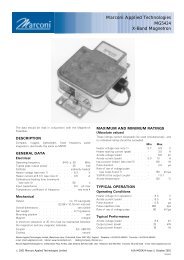
Marconi Applied Technologies MG5241 X-Band Magnetron
Marconi Applied Technologies MG5241 X-Band Magnetron
Marconi Applied Technologies MG5241 X-Band Magnetron

Create successful ePaper yourself
Turn your PDF publications into a flip-book with our unique Google optimized e-Paper software.
TEST CONDITIONS AND LIMITS<br />
The magnetron is tested to comply with the following electrical<br />
specification.<br />
Test Conditions<br />
Heater voltage (for test) . . . . . . . . 6.3 V<br />
Anode current (mean) . . . . . . . . 5.0 mA<br />
Duty cycle . . . . . . . . . . . . 0.001<br />
Pulse duration (see note 6) . . . . . . . 1.0 ms<br />
VSWR at the output coupler . . . . . . 1.15:1 max<br />
Rate of rise of voltage pulse (see note 4):<br />
using hard tube pulser . . . . . . 150 kV/ms min<br />
alternatively using line type pulser . . . . 75 kV/ms min<br />
Limits<br />
Min Max<br />
Anode voltage (peak) . . . . . . . 5.4 6.0 kV<br />
Output power (mean) . . . . . 10 – W<br />
Frequency (see note 7) . . . . . 9380 9440 MHz<br />
RF bandwidth at 1 / 4 power . . . . . – 2.5 MHz<br />
Frequency pulling<br />
(VSWR not less than 1.5:1) . . . . – 23 MHz<br />
Stability (see note 8) . . . . . . . – 0.05 %<br />
Cold impedance . . . . . . . . . . . see note 9<br />
Heater current . . . . . . . . . . . . see note 10<br />
Temperature coefficient of frequency . . . . see note 11<br />
LIFE TEST<br />
The quality of all production is monitored by the random<br />
selection of tubes which are then life-tested under Test<br />
Conditions Oscillation 1. If the tube is to be operated under<br />
conditions other than those specified herein, <strong>Marconi</strong> <strong>Applied</strong><br />
<strong>Technologies</strong> should be consulted to verify that the life of the<br />
magnetron will not be impaired.<br />
End of Life Criteria<br />
(under Test Conditions Oscillation 1)<br />
Anode voltage (peak) . . . . . 5.4 to 6.1 kV<br />
Output power (mean) . . . . . . . 9.0 W min<br />
RF bandwidth at 1 / 4 power . . . . . . 3.5 MHz max<br />
Frequency . . . . . . . 9380 to 9440 MHz<br />
NOTES<br />
1. No reduction of heater voltage is required at any value of<br />
mean input power. For optimum performance a value<br />
within the specified ratings must be maintained.<br />
The magnetron heater must be protected against arcing by<br />
the use of a minimum capacitance of 4000 pF shunted<br />
across the heater directly at the input terminals; in some<br />
cases a capacitance as high as 2 mF may be necessary<br />
depending on the equipment design. For further details see<br />
the <strong>Magnetron</strong> Preamble.<br />
2. For ambient temperatures above 0 8C. For ambient<br />
temperatures between 0 and 755 8C, cathode pre-heating<br />
time is 75 seconds minimum.<br />
3. The various parameters are related by the following<br />
formula:<br />
Pi = i apk xv apk xDu<br />
where Pi = mean input power in watts<br />
i apk = peak anode current in amperes<br />
v apk = peak anode voltage in volts<br />
and Du = duty cycle.<br />
4. Defined as the steepest tangent to the leading edge of the<br />
voltage pulse above 80% amplitude. Any capacitance in<br />
the viewing system must not exceed 6.0 pF.<br />
5. The maximum rate of rise of voltage for stable operation<br />
depends upon detailed characteristics of the applied pulse<br />
and the pulser design. The specified maximum rating<br />
applies to typical hard tube pulsers. For minimum starting<br />
jitter and optimum operation, the recommended rate of<br />
rise of voltage for most line type pulsers is from 50 to<br />
65 kV/ms.<br />
6. Tolerance + 10%.<br />
7. Other frequency ranges can be supplied on request.<br />
8. With the magnetron operating into a VSWR of 1.15:1 over<br />
a peak anode current range of 3.0 to 6.0 A. Pulses are<br />
defined as missing when the RF energy level is less than<br />
70% of the normal energy level in a 0.5% frequency<br />
range. Missing pulses are expressed as a percentage of<br />
the number of input pulses applied during a two minute<br />
period of observation.<br />
9. The impedance of the magnetron measured at the operating<br />
frequency when not oscillating will be such as to give a<br />
VSWR of at least 6:1, with a voltage minimum 16.5 to<br />
22.5 mm from the output flange towards the anode.<br />
10. Measured with heater voltage of 6.3 V and no anode input<br />
power, the heater current limits are 0.5 A minimum, 0.6 A<br />
maximum.<br />
11. Design test only. The maximum frequency change with<br />
anode temperature change (after warming) is<br />
70.25 MHz/8C.<br />
<strong>MG5241</strong>, page 2<br />
#2001 <strong>Marconi</strong> <strong>Applied</strong> <strong>Technologies</strong>