Marconi Applied Technologies MG5241 X-Band Magnetron
Marconi Applied Technologies MG5241 X-Band Magnetron
Marconi Applied Technologies MG5241 X-Band Magnetron

Create successful ePaper yourself
Turn your PDF publications into a flip-book with our unique Google optimized e-Paper software.
<strong>Marconi</strong> <strong>Applied</strong> <strong>Technologies</strong><br />
<strong>MG5241</strong><br />
X-<strong>Band</strong> <strong>Magnetron</strong><br />
The data should be read in conjunction with the <strong>Magnetron</strong><br />
Preamble.<br />
ABRIDGED DATA<br />
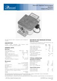
Compact, rugged, lightweight, fixed frequency pulse magnetron.<br />
Operating frequency . . . . . . 9410 + 30 MHz<br />
Typical peak output power . . . . . . 12.5 kW<br />
Magnet . . . . . . . . . . . . . . . integral<br />
Output . . . . . . . . . . . . no. 16 waveguide<br />
(22.86 x 10.16 mm internal)<br />
Coupler . . . . . . . . . . . . . IEC UBR100<br />
Cooling . . . . . . . . . . . . . . . natural<br />
GENERAL<br />
Electrical<br />
Cathode . . . . . . . . . . . . indirectly heated<br />
Heater voltage (see note 1) . . . . . . . 6.3 V<br />
Heater current at 6.3 V . . . . . . . . 0.5 A<br />
Cathode pre-heating time (minimum)<br />
(see note 2) . . . . . . . . . . 60 s<br />
Input capacitance . . . . . . . . . . 8.0 pF max<br />
Mechanical<br />
Overall dimensions . . . . . . . . . . . see outline<br />
Net weight . . . . . . . . . . . . 0.7 kg approx<br />
Mounting position . . . . . . . . . . . . . any<br />
A minimum clearance of 25 mm must be maintained between<br />
the magnetron and any magnetic materials.<br />
Cooling . . . . . . . . . . . . . . . natural<br />
MAXIMUM AND MINIMUM RATINGS<br />
(Absolute values)<br />
These ratings cannot necessarily be used simultaneously, and<br />
no individual rating should be exceeded.<br />
Min Max<br />
Heater voltage (see note 1) . . . . . 5.7 6.9 V<br />
Heater starting current (peak) . . . . – 3.0 A<br />
Anode voltage (peak) . . . . . . . 5.4 6.4 kV<br />
Anode current (peak) . . . . . . . 3.0 6.0 A<br />
Input power (mean) (see note 3) . . . – 70 W<br />
Duty cycle . . . . . . . . . . – 0.0025<br />
Pulse duration . . . . . . . . . – 2.5 ms<br />
Rate of rise of voltage pulse<br />
(see notes 4 and 5) . . . . . . . – 150 kV/ms<br />
VSWR at the output coupler . . . . – 1.5:1<br />
TYPICAL OPERATION<br />
Operating Conditions<br />
Heater voltage (for operation) . . . . . . 6.3 V<br />
Anode current (peak) . . . . . . . . . 5.0 A<br />
Pulse duration . . . . . . . . . . . 1.0 ms<br />
Pulse repetition rate . . . . . . . . 1000 pps<br />
Rate of rise of voltage pulse . . . . . . 60 kV/ms<br />
Typical Performance<br />
Anode voltage (peak) . . . . . . . . . 5.8 kV<br />
Output power (peak) . . . . . . . . 12.5 kW<br />
Output power (mean) . . . . . . . . 12.5 W<br />
<strong>Marconi</strong> <strong>Applied</strong> <strong>Technologies</strong> Limited, Waterhouse Lane, Chelmsford, Essex CM1 2QU England Telephone: +44 (0)1245 493493 Facsimile: +44 (0)1245 492492<br />
e-mail: mtech.uk@marconi.com Internet: www.marconitech.com Holding Company: <strong>Marconi</strong> p.l.c.<br />
<strong>Marconi</strong> <strong>Applied</strong> <strong>Technologies</strong> Inc. 4 Westchester Plaza, PO Box 1482, Elmsford, NY10523-1482 USA Telephone: (914) 592-6050 Facsimile: (914) 592-5148 e-mail: mtech.usa@marconi.com<br />
#2001 <strong>Marconi</strong> <strong>Applied</strong> <strong>Technologies</strong> Limited A1A-<strong>MG5241</strong> Issue 4, October 2001<br />
181/5765
TEST CONDITIONS AND LIMITS<br />
The magnetron is tested to comply with the following electrical<br />
specification.<br />
Test Conditions<br />
Heater voltage (for test) . . . . . . . . 6.3 V<br />
Anode current (mean) . . . . . . . . 5.0 mA<br />
Duty cycle . . . . . . . . . . . . 0.001<br />
Pulse duration (see note 6) . . . . . . . 1.0 ms<br />
VSWR at the output coupler . . . . . . 1.15:1 max<br />
Rate of rise of voltage pulse (see note 4):<br />
using hard tube pulser . . . . . . 150 kV/ms min<br />
alternatively using line type pulser . . . . 75 kV/ms min<br />
Limits<br />
Min Max<br />
Anode voltage (peak) . . . . . . . 5.4 6.0 kV<br />
Output power (mean) . . . . . 10 – W<br />
Frequency (see note 7) . . . . . 9380 9440 MHz<br />
RF bandwidth at 1 / 4 power . . . . . – 2.5 MHz<br />
Frequency pulling<br />
(VSWR not less than 1.5:1) . . . . – 23 MHz<br />
Stability (see note 8) . . . . . . . – 0.05 %<br />
Cold impedance . . . . . . . . . . . see note 9<br />
Heater current . . . . . . . . . . . . see note 10<br />
Temperature coefficient of frequency . . . . see note 11<br />
LIFE TEST<br />
The quality of all production is monitored by the random<br />
selection of tubes which are then life-tested under Test<br />
Conditions Oscillation 1. If the tube is to be operated under<br />
conditions other than those specified herein, <strong>Marconi</strong> <strong>Applied</strong><br />
<strong>Technologies</strong> should be consulted to verify that the life of the<br />
magnetron will not be impaired.<br />
End of Life Criteria<br />
(under Test Conditions Oscillation 1)<br />
Anode voltage (peak) . . . . . 5.4 to 6.1 kV<br />
Output power (mean) . . . . . . . 9.0 W min<br />
RF bandwidth at 1 / 4 power . . . . . . 3.5 MHz max<br />
Frequency . . . . . . . 9380 to 9440 MHz<br />
NOTES<br />
1. No reduction of heater voltage is required at any value of<br />
mean input power. For optimum performance a value<br />
within the specified ratings must be maintained.<br />
The magnetron heater must be protected against arcing by<br />
the use of a minimum capacitance of 4000 pF shunted<br />
across the heater directly at the input terminals; in some<br />
cases a capacitance as high as 2 mF may be necessary<br />
depending on the equipment design. For further details see<br />
the <strong>Magnetron</strong> Preamble.<br />
2. For ambient temperatures above 0 8C. For ambient<br />
temperatures between 0 and 755 8C, cathode pre-heating<br />
time is 75 seconds minimum.<br />
3. The various parameters are related by the following<br />
formula:<br />
Pi = i apk xv apk xDu<br />
where Pi = mean input power in watts<br />
i apk = peak anode current in amperes<br />
v apk = peak anode voltage in volts<br />
and Du = duty cycle.<br />
4. Defined as the steepest tangent to the leading edge of the<br />
voltage pulse above 80% amplitude. Any capacitance in<br />
the viewing system must not exceed 6.0 pF.<br />
5. The maximum rate of rise of voltage for stable operation<br />
depends upon detailed characteristics of the applied pulse<br />
and the pulser design. The specified maximum rating<br />
applies to typical hard tube pulsers. For minimum starting<br />
jitter and optimum operation, the recommended rate of<br />
rise of voltage for most line type pulsers is from 50 to<br />
65 kV/ms.<br />
6. Tolerance + 10%.<br />
7. Other frequency ranges can be supplied on request.<br />
8. With the magnetron operating into a VSWR of 1.15:1 over<br />
a peak anode current range of 3.0 to 6.0 A. Pulses are<br />
defined as missing when the RF energy level is less than<br />
70% of the normal energy level in a 0.5% frequency<br />
range. Missing pulses are expressed as a percentage of<br />
the number of input pulses applied during a two minute<br />
period of observation.<br />
9. The impedance of the magnetron measured at the operating<br />
frequency when not oscillating will be such as to give a<br />
VSWR of at least 6:1, with a voltage minimum 16.5 to<br />
22.5 mm from the output flange towards the anode.<br />
10. Measured with heater voltage of 6.3 V and no anode input<br />
power, the heater current limits are 0.5 A minimum, 0.6 A<br />
maximum.<br />
11. Design test only. The maximum frequency change with<br />
anode temperature change (after warming) is<br />
70.25 MHz/8C.<br />
<strong>MG5241</strong>, page 2<br />
#2001 <strong>Marconi</strong> <strong>Applied</strong> <strong>Technologies</strong>
PERFORMANCE CHART<br />
7<br />
5177A<br />
6<br />
MAXIMUM<br />
TYPICAL<br />
5<br />
MINIMUM<br />
4<br />
3<br />
PEAK OUTPUT POWER (kW) PEAK ANODE VOLTAGE (kV)<br />
2<br />
1<br />
0<br />
20<br />
15<br />
10<br />
5<br />
PEAK CURRENT<br />
RATING LIMITS<br />
TYPICAL<br />
MINIMUM<br />
0 0 1 2 3 4 5 6 7 8<br />
PEAK ANODE CURRENT (A)<br />
HEALTH AND SAFETY HAZARDS<br />
<strong>Marconi</strong> <strong>Applied</strong> <strong>Technologies</strong> magnetrons are safe to handle<br />
and operate, provided that the relevant precautions stated<br />
herein are observed. <strong>Marconi</strong> <strong>Applied</strong> <strong>Technologies</strong> does not<br />
accept responsibility for damage or injury resulting from the use<br />
of electronic devices it produces. Equipment manufacturers and<br />
users must ensure that adequate precautions are taken.<br />
Appropriate warning labels and notices must be provided on<br />
equipments incorporating <strong>Marconi</strong> <strong>Applied</strong> <strong>Technologies</strong><br />
devices and in operating manuals.<br />
High Voltage<br />
Equipment must be designed so that personnel cannot come<br />
into contact with high voltage circuits. All high voltage circuits<br />
and terminals must be enclosed and fail-safe interlock switches<br />
must be fitted to disconnect the primary power supply and<br />
discharge all high voltage capacitors and other stored charges<br />
before allowing access. Interlock switches must not be<br />
bypassed to allow operation with access doors open.<br />
RF Radiation<br />
Personnel must not be exposed to excessive RF radiation. All<br />
RF connectors must be correctly fitted before operation so that<br />
no leakage of RF energy can occur and the RF output must be<br />
coupled efficiently to the load. It is particularly dangerous to<br />
look into open waveguide or coaxial feeders while the device is<br />
energised. Screening of the cathode sidearm of high power<br />
magnetrons may be necessary.<br />
X-Ray Radiation<br />
High voltage magnetrons emit a significant intensity of X-rays<br />
not only from the cathode sidearm but also from the output<br />
waveguide. These rays can constitute a health hazard unless<br />
adequate shielding for X-ray radiation is provided. This is a<br />
characteristic of all magnetrons and the X-rays emitted<br />
correspond to a voltage much higher than that of the anode.<br />
#2001 <strong>Marconi</strong> <strong>Applied</strong> <strong>Technologies</strong> <strong>MG5241</strong>, page 3
OUTLINE<br />
(All dimensions without limits are nominal)<br />
5039F<br />
G<br />
H<br />
J<br />
SEE NOTE 1<br />
2 HOLES 1L<br />
SEE NOTE 2<br />
K<br />
M<br />
D<br />
A<br />
T<br />
2 HOLES 1N<br />
BY S DEEP<br />
SEE NOTE 2<br />
E<br />
2 HOLES 1N<br />
SEE NOTE 2<br />
F<br />
P<br />
T<br />
Q<br />
C<br />
R<br />
R<br />
B<br />
Ref<br />
Millimetres<br />
A 113.0 max<br />
B 41.53 max<br />
C 35.0 max<br />
D 87.0 max<br />
E 10.0 min<br />
F 3.33 max<br />
G 240.0 min<br />
H 52.5 max<br />
J 30.0 max<br />
K 21.5 max<br />
4.52 max<br />
L<br />
4.37 min<br />
M 87.95<br />
4.39 max<br />
N<br />
4.24 min<br />
P 20.2 max<br />
Q 5.15 + 0.10<br />
R 15.5<br />
S 5.00 min<br />
T 16.26<br />
Lead Connections<br />
Colour<br />
Green<br />
Yellow<br />
Element<br />
Heater<br />
Heater, cathode<br />
Outline Notes<br />
1. The mating surface of the magnetron baseplate will be flat<br />
to within 0.20 mm.<br />
2. Positional tolerance of holes +0.2 mm with respect to<br />
waveguide aperture.<br />
Whilst <strong>Marconi</strong> <strong>Applied</strong> <strong>Technologies</strong> has taken care to ensure the accuracy of the information contained herein it accepts no responsibility for the consequences of any<br />
use thereof and also reserves the right to change the specification of goods without notice. <strong>Marconi</strong> <strong>Applied</strong> <strong>Technologies</strong> accepts no liability beyond that set out in its<br />
standard conditions of sale in respect of infringement of third party patents arising from the use of tubes or other devices in accordance with information contained herein.<br />
<strong>MG5241</strong>, page 4<br />
Printed in England<br />
#2001 <strong>Marconi</strong> <strong>Applied</strong> <strong>Technologies</strong>