Markings - Maryland State Highway Administration
Markings - Maryland State Highway Administration
Markings - Maryland State Highway Administration

Create successful ePaper yourself
Turn your PDF publications into a flip-book with our unique Google optimized e-Paper software.
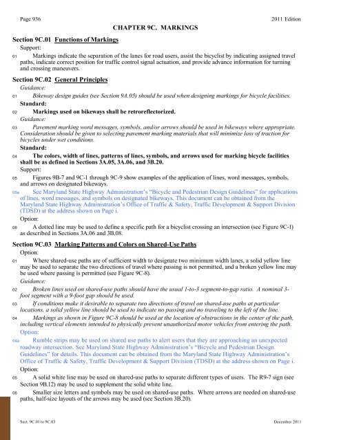
Page 936<br />
CHAPTER 9C. MARKINGS<br />
2011 Edition<br />
Section 9C.01 Functions of <strong>Markings</strong><br />
Support:<br />
01 <strong>Markings</strong> indicate the separation of the lanes for road users, assist the bicyclist by indicating assigned travel<br />
paths, indicate correct position for traffic control signal actuation, and provide advance information for turning<br />
and crossing maneuvers.<br />
Section 9C.02 General Principles<br />
Guidance:<br />
01 Bikeway design guides (see Section 9A.05) should be used when designing markings for bicycle facilities.<br />
Standard:<br />
02 <strong>Markings</strong> used on bikeways shall be retroreflectorized.<br />
Guidance:<br />
03 Pavement marking word messages, symbols, and/or arrows should be used in bikeways where appropriate.<br />
Consideration should be given to selecting pavement marking materials that will minimize loss of traction for<br />
bicycles under wet conditions.<br />
Standard:<br />
04 The colors, width of lines, patterns of lines, symbols, and arrows used for marking bicycle facilities<br />
shall be as defined in Sections 3A.05, 3A.06, and 3B.20.<br />
Support:<br />
05 Figures 9B-7 and 9C-1 through 9C-9 show examples of the application of lines, word messages, symbols,<br />
and arrows on designated bikeways.<br />
05a See <strong>Maryland</strong> <strong>State</strong> <strong>Highway</strong> <strong>Administration</strong>’s “Bicycle and Pedestrian Design Guidelines” for applications<br />
of lines, word messages, and symbols on designated bikeways. This document can be obtained from the<br />
<strong>Maryland</strong> <strong>State</strong> <strong>Highway</strong> <strong>Administration</strong>’s Office of Traffic & Safety, Traffic Development & Support Division<br />
(TDSD) at the address shown on Page i.<br />
Option:<br />
06 A dotted line may be used to define a specific path for a bicyclist crossing an intersection (see Figure 9C-1)<br />
as described in Sections 3A.06 and 3B.08.<br />
Section 9C.03 Marking Patterns and Colors on Shared-Use Paths<br />
Option:<br />
01 Where shared-use paths are of sufficient width to designate two minimum width lanes, a solid yellow line<br />
may be used to separate the two directions of travel where passing is not permitted, and a broken yellow line may<br />
be used where passing is permitted (see Figure 9C-8).<br />
Guidance:<br />
02 Broken lines used on shared-use paths should have the usual 1-to-3 segment-to-gap ratio. A nominal 3-<br />
foot segment with a 9-foot gap should be used.<br />
03 If conditions make it desirable to separate two directions of travel on shared-use paths at particular<br />
locations, a solid yellow line should be used to indicate no passing and no traveling to the left of the line.<br />
04 <strong>Markings</strong> as shown in Figure 9C-8 should be used at the location of obstructions in the center of the path,<br />
including vertical elements intended to physically prevent unauthorized motor vehicles from entering the path.<br />
Option:<br />
04a Rumble strips may be used on shared use paths to alert users that they are approaching an unexpected<br />
roadway intersection. See <strong>Maryland</strong> <strong>State</strong> <strong>Highway</strong> <strong>Administration</strong>’s “Bicycle and Pedestrian Design<br />
Guidelines” for details. This document can be obtained from the <strong>Maryland</strong> <strong>State</strong> <strong>Highway</strong> <strong>Administration</strong>’s<br />
Office of Traffic & Safety, Traffic Development & Support Division (TDSD) at the address shown on Page i.<br />
Option:<br />
05 A solid white line may be used on shared-use paths to separate different types of users. The R9-7 sign (see<br />
Section 9B.12) may be used to supplement the solid white line.<br />
06 Smaller size letters and symbols may be used on shared-use paths. Where arrows are needed on shared-use<br />
paths, half-size layouts of the arrows may be used (see Section 3B.20).<br />
Sect. 9C.01 to 9C.03 December 2011
2011 Edition Page 937<br />
Figure 9C-1. Example of Intersection Pavement <strong>Markings</strong>—Designated<br />
Bicycle Lane with Left-Turn Area, Heavy Turn Volumes, Parking,<br />
One-Way Traffic, or Divided <strong>Highway</strong><br />
See Figure 3A-1a for spacing<br />
of Type III Dotted Line.<br />
*<br />
*<br />
*<br />
**<br />
Note:<br />
For marking of the pocket<br />
lane, see <strong>Maryland</strong> <strong>State</strong><br />
<strong>Highway</strong> <strong>Administration</strong>’s<br />
Bicycle and Pedestrian<br />
Design Guidelines.<br />
See Chapter 3B for<br />
pavement marking arrow<br />
use.<br />
** **<br />
R3-7R<br />
or<br />
R3-7(1)R<br />
50 ft MIN.<br />
See Figure 3A-1a for<br />
spacing of Type I Dotted Line.<br />
R4-4<br />
December 2011 Sect. 9C.04
Page 938<br />
2011 Edition<br />
Figure 9C-2. Examples of Center Line <strong>Markings</strong> for Shared-Use Paths<br />
9 ft<br />
3 ft<br />
Normal<br />
width broken<br />
yellow line<br />
Normal<br />
width solid<br />
yellow line<br />
A - Passing permitted<br />
B - Passing NOT permitted<br />
Section 9C.04 <strong>Markings</strong> For Bicycle Lanes<br />
Support:<br />
01 Pavement markings designate that portion of the roadway for preferential use by bicyclists. <strong>Markings</strong> inform<br />
all road users of the restricted nature of the bicycle lane.<br />
Standard:<br />
02 Longitudinal pavement markings shall be used to define bicycle lanes.<br />
Guidance:<br />
03 If used, bicycle lane word, symbol, and/or arrow markings (see Figure 9C-3) should be placed at the<br />
beginning of a bicycle lane and at periodic intervals along the bicycle lane based on engineering judgment.<br />
Standard:<br />
04 If the bicycle lane symbol marking is used in conjunction with word or arrow messages, it shall precede them.<br />
Option:<br />
05 If the word, symbol, and/or arrow pavement markings shown in Figure 9C-3 are used, Bike Lane signs (see<br />
Section 9B.04) may also be used, but to avoid overuse of the signs not necessarily adjacent to every set of<br />
pavement markings.<br />
Sect. 9C.04 December 2011
2011 Edition Page 939<br />
Figure 9C-3. Word, Symbol, and Arrow Pavement <strong>Markings</strong> for Bicycle Lanes<br />
Normal<br />
white line<br />
Normal<br />
white line<br />
Normal white line<br />
72 inches<br />
Legend<br />
Optional<br />
72 inches<br />
72 inches<br />
72 inches<br />
72 inches<br />
72 inches<br />
44 inches<br />
64 inches<br />
72 inches<br />
72 inches<br />
44 inches<br />
A - Bike Symbol<br />
B - Helmeted Bicyclist Symbol<br />
C - Word Legends<br />
When required, Option A shall be used on <strong>State</strong> owned, operated, and maintained roadways.<br />
Standard:<br />
06 A through bicycle lane shall not be positioned to the right of a right turn only lane or to the left of a<br />
left turn only lane.<br />
Support:<br />
07 A bicyclist continuing straight through an intersection from the right of a right-turn lane or from the left of a<br />
left-turn lane would be inconsistent with normal traffic behavior and would violate the expectations of right- or<br />
left-turning motorists.<br />
Guidance:<br />
08 When the right through lane is dropped to become a right turn only lane, the bicycle lane markings should<br />
stop at least 100 feet before the beginning of the right-turn lane. Through bicycle lane markings should resume<br />
to the left of the right turn only lane.<br />
09 An optional through-right turn lane next to a right turn only lane should not be used where there is a<br />
through bicycle lane. If a capacity analysis indicates the need for an optional through-right turn lane, the<br />
bicycle lane should be discontinued at the intersection approach.<br />
10 Posts or raised pavement markers should not be used to separate bicycle lanes from adjacent travel lanes.<br />
December 2011 Sect. 9C.04
Page 940<br />
Support:<br />
2011 Edition<br />
11 Using raised devices creates a collision potential for bicyclists by placing fixed objects immediately adjacent<br />
to the travel path of the bicyclist. In addition, raised devices can prevent vehicles turning right from merging with<br />
the bicycle lane, which is the preferred method for making the right turn. Raised devices used to define a bicycle<br />
lane can also cause problems in cleaning and maintaining the bicycle lane.<br />
Standard:<br />
12 Bicycle lanes shall not be provided on the circular roadway of a roundabout.<br />
Guidance:<br />
13 Bicycle lane markings should stop at least 100 feet before the crosswalk, or if no crosswalk is provided, at<br />
least 100 feet before the yield line, or if no yield line is provided, then at least 100 feet before the edge of the<br />
circulatory roadway.<br />
Support:<br />
14 Examples of bicycle lane markings at right-turn lanes are shown in Figures 9C-1, 9C-4, and 9C-5. Examples<br />
of pavement markings for bicycle lanes on a two-way street are shown in Figure 9C-6. Pavement word message,<br />
symbol, and arrow markings for bicycle lanes are shown in Figure 9C-3.<br />
Section 9C.05 Bicycle Detector Symbol<br />
Option:<br />
01 A symbol (see Figure 9C-7) may be placed on the pavement indicating the optimum position for a bicyclist<br />
to actuate the signal.<br />
02 An R10-22 sign (see Section 9B.13 and Figure 9B-2) may be installed to supplement the pavement marking.<br />
Section 9C.06 Pavement <strong>Markings</strong> for Obstructions<br />
Guidance:<br />
01 In roadway situations where it is not practical to eliminate a drain grate or other roadway obstruction that<br />
is inappropriate for bicycle travel, white markings applied as shown in Figure 9C-8 should be used to guide<br />
bicyclists around the condition.<br />
Section 9C.07 Shared Lane Marking<br />
Option:<br />
01 The Shared Lane Marking shown in Figure 9C-9 may be used to:<br />
A. Assist bicyclists with lateral positioning in a shared lane with on-street parallel parking in order to<br />
reduce the chance of a bicyclist’s impacting the open door of a parked vehicle,<br />
B. Assist bicyclists with lateral positioning in lanes that are too narrow for a motor vehicle and a bicycle to<br />
travel side by side within the same traffic lane,<br />
C. Alert road users of the lateral location bicyclists are likely to occupy within the traveled way,<br />
D. Encourage safe passing of bicyclists by motorists, and<br />
E. Reduce the incidence of wrong-way bicycling.<br />
Guidance:<br />
02 The Shared Lane Marking should not be placed on roadways that have a speed limit above 35 mph.<br />
Standard:<br />
03 Shared Lane <strong>Markings</strong> shall not be used on shoulders or in designated bicycle lanes.<br />
Guidance:<br />
04 If used in a shared lane with on-street parallel parking, Shared Lane <strong>Markings</strong> should be placed so that the<br />
centers of the markings are at least 11 feet from the face of the curb, or from the edge of the pavement where<br />
there is no curb.<br />
05 If used on a street without on-street parking that has an outside travel lane that is less than 14 feet wide, the<br />
centers of the Shared Lane <strong>Markings</strong> should be at least 4 feet from the face of the curb, or from the edge of the<br />
pavement where there is no curb.<br />
06 If used, the Shared Lane Marking should be placed immediately after an intersection and spaced at<br />
intervals not greater than 250 feet thereafter.<br />
Option:<br />
07 Section 9B.06 describes a Bicycles May Use Full Lane sign that may be used in addition to or instead of the<br />
Shared Lane Marking to inform road users that bicyclists might occupy the travel lane.<br />
07a The NOTICE (W16-18P) Plaque may be used to supplement the use of the Bicycle May Use Full Lane (R4-<br />
11) sign.<br />
Sect. 9C.04 to 9C.07 December 2011
2011 Edition Page 941<br />
Figure 9C-4. Example of Bicycle Lane Treatment at a Right Turn Only Lane<br />
* **<br />
R3-7R<br />
or<br />
R3-7(1)R<br />
See Figure 3A-1a for<br />
spacing of Type I Dotted Line.<br />
R4-4 at upstream end of<br />
right turn only lane taper<br />
*<br />
**<br />
Note:<br />
For marking of the pocket<br />
lane, see <strong>Maryland</strong> <strong>State</strong><br />
<strong>Highway</strong> <strong>Administration</strong>’s<br />
Bicycle and Pedestrian<br />
Design Guidelines.<br />
See Chapter 3B for<br />
pavement marking arrow<br />
use.<br />
December 2011 Sect. 9C.07
Page 942<br />
Figure 9C-4a. Example of Typical Shoulder Bicycle Lane<br />
Changes to Right Turn Lane With Pocket Lane<br />
2011 Edition<br />
*<br />
See Figure 3A-1a for<br />
spacing of Type I Dotted Line.<br />
R4-4<br />
*<br />
Note:<br />
See Chapter 3B<br />
for pavement marking arrow<br />
use.<br />
Sect. 9C.07 December 2011
2011 Edition Page 943<br />
Figure 9C-5. Example of Bicycle Lane Treatment at Parking Lane<br />
into a Right Turn Only Lane<br />
* **<br />
R3-7R<br />
or<br />
R3-7(1)R<br />
See Figure 3A-1a for<br />
spacing of Type I Dotted Line.<br />
R4-4 at upstream end<br />
of right turn only lane<br />
*<br />
**<br />
Note:<br />
For marking of the pocket<br />
lane, see <strong>Maryland</strong> <strong>State</strong><br />
<strong>Highway</strong> <strong>Administration</strong>’s<br />
Bicycle and Pedestrian<br />
Design Guidelines.<br />
See Chapter 3B for<br />
pavement marking arrow<br />
use.<br />
December 2011 Sect. 9C.07
Page 944<br />
2011 Edition<br />
Figure 9C-6. Example of Pavement <strong>Markings</strong> for Bicycle Lanes<br />
on a Two-Way Street<br />
R3-17<br />
R7 series sign<br />
(as appropriate)<br />
Minor intersection<br />
R8-3<br />
R3-17<br />
50 to 200 feet of dotted<br />
line if bus stop or heavy<br />
right-turn volume<br />
Normal width<br />
solid white line<br />
Example of application<br />
where parking is prohibited<br />
Example of application<br />
where parking is permitted<br />
Normal width solid white line<br />
Normal width solid<br />
white line (optional)<br />
R3-17<br />
R7 series sign<br />
(as appropriate)<br />
Signalized intersection<br />
Note:<br />
For marking of the pocket<br />
lane, see <strong>Maryland</strong> <strong>State</strong><br />
<strong>Highway</strong> <strong>Administration</strong>’s<br />
Bicycle and Pedestrian<br />
Design Guidelines.<br />
R8-3<br />
R3-17<br />
Dotted line for bus stops<br />
immediately beyond the<br />
intersection is optional;<br />
otherwise use normal<br />
width solid white line<br />
50 to 200 feet of dotted line -<br />
2-foot line, 6-foot space<br />
Sect. 9C.07 December 2011
2011 Edition<br />
Page 945<br />
Figure 9C-6a. Example of Typical Shoulder Bicycle Lane<br />
Changes to Right Turn Lane Without Pocket Lane<br />
R3-17<br />
R3-17a<br />
R4-4<br />
R3-17<br />
R3-17b<br />
December 2011<br />
Sect. 9C.07
Page 946<br />
2011 Edition<br />
Figure 9C-6b. Example of Typical Shoulder Bicycle Lane<br />
Changes to Left Turn Bypass Lane Without Continuing Bike Lane<br />
R3-17<br />
R3-17a<br />
R3-17<br />
R3-17b<br />
Sect. 9C.07 December 2011
2011 Edition Page 947<br />
Figure 9C-7. Bicycle Detector Pavement Marking<br />
6 inches<br />
5 inches<br />
24 inches<br />
2 inches<br />
6 inches<br />
2<br />
inches<br />
December 2011 Sect. 9C.07
Page 948<br />
2011 Edition<br />
Figure 9C-8. Examples of Obstruction Pavement <strong>Markings</strong><br />
10 ft 1 ft<br />
Obstruction<br />
Normal width solid yellow line<br />
A - Obstruction within the path<br />
W<br />
Pier, abutment, grate, or other obstruction<br />
Wide solid white line (see Section 3A.06)<br />
Direction of bicycle travel<br />
B - Obstruction at edge of path or roadway<br />
L = WS, where W is the offset in feet and S is bicycle approach speed in mph<br />
Provide an additional foot of offset for a raised obstruction and use the formula<br />
L = (W+1) S for the taper length<br />
Figure 9C-9. Shared Lane Marking<br />
112 inches<br />
72 inches<br />
40 inches<br />
Sect. 9C.07 December 2011