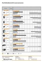
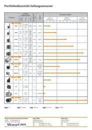
SIGNAL CONDITIONER PMX-24
- Converts potentiometer signals into analog output signals (e.g. 0...10 V or 4...20 mA) - With cable break detection and alarm output - Input: potentiometer 1...20 kΩ - Differential potentiometer supply - Configurable output - Electrically isolated - High interference resistance - Low residual ripple - DIN rail mounting
- Converts potentiometer signals into analog
output signals (e.g. 0...10 V or 4...20 mA)
- With cable break detection and alarm output
- Input: potentiometer 1...20 kΩ
- Differential potentiometer supply
- Configurable output
- Electrically isolated
- High interference resistance
- Low residual ripple
- DIN rail mounting

Create successful ePaper yourself
Turn your PDF publications into a flip-book with our unique Google optimized e-Paper software.
<strong>SIGNAL</strong> <strong>CONDITIONER</strong><br />
<strong>PMX</strong>-<strong>24</strong> Signal Conditioner<br />
Key Features:<br />
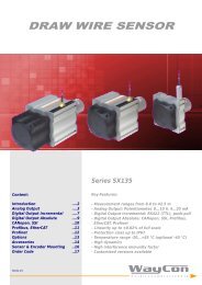
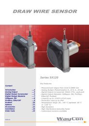
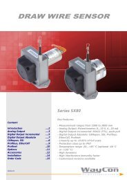
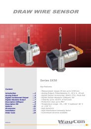
Content:<br />
Introduction ....2<br />
Technical Data ....2<br />
Cable Break Detection ....3<br />
Electrical Connection ....3<br />
Settings ....4<br />
- Converts potentiometer signals into analog<br />
output signals (e.g. 0...10 V or 4...20 mA)<br />
- With cable break detection and alarm output<br />
- Input: potentiometer 1...20 kΩ<br />
- Differential potentiometer supply<br />
- Configurable output<br />
- Electrically isolated<br />
- High interference resistance<br />
- Low residual ripple<br />
- DIN rail mounting<br />
10.12.14
- 2 -<br />
INTRODUCTION<br />
Signal conditioners are used for potentiometers to convert an input signal into a different proportional output signal. These are often standardised values such as<br />
0...10 V or 4...20 mA, needed for ordinary connection to controls. A signal conditioning and an electrical isolation ensures an optimal signal performance.<br />
The <strong>PMX</strong>-<strong>24</strong> offers various current and voltage outputs, e.g. 4...20 mA, 0...10 V, 0...5 V, ±5 V, ±10 V, which can be configured easily via DIP switch (switch on the<br />
board). The signal output is electrically isolated and characterised by extremely low residual noise, free of any spikes. Concerning the interference, the supply of the<br />
potentiometer is realised with a high precise differential voltage reference of ±5 V, therefore longer cables can be used between the potentiometer and conditioner<br />
and signal interference by external system parts are minimised.<br />
TECHNICAL DATA<br />
<strong>PMX</strong>-<strong>24</strong><br />
Output<br />
4...20 mA, 0...10 V, 0...5 V, ±10 V, ±5 V, adjustable via DIP<br />
switch, electrically isolated, 4 wire technology<br />
Input<br />
Supply<br />
Potentiometer with 1...20 kΩ<br />
9...36 VDC<br />
Max. supply current<br />
Max. shunt current output<br />
Dynamic<br />
Noise<br />
30 mA, max. 44 mA (with current output in use)<br />
< 300 Ω<br />
300 Hz (-3 dB) active 6-pole Bessel filter<br />
15°C 0.00005 %/K<br />
Power-on drift<br />
0.0025% of FS without warming up<br />
Connection technology<br />
4 wire technology<br />
Protection class<br />
IP30 (EN60529)<br />
Circuit diagram<br />
V+ Pin 1: Screen<br />
Pin 2: GND<br />
+<br />
Pin 3: 9...36 VDC<br />
Pin 4: Alarm 1<br />
Pin 5: Pot +<br />
Pin 6: Cursor<br />
Pin 7: Pot -<br />
Pin 8: Screen<br />
A<br />
V<br />
Pin 10: Alarm 2<br />
Pin 11: GND (Signal)<br />
Pin 12: Voltage<br />
Pin 13: Current<br />
Note:<br />
GND signal and GND can be connected if 3 wire<br />
technology is used.<br />
Pin 1 and Pin 8 are internally connected.<br />
TECHNICAL DRAWING
- 3 -<br />
CABLE BREAK DETECTION<br />
In case of a cable break between the sensor and transducer, there is no signal at the electronics input. Conventional devices would detect this as the cursor signal in<br />
accordance with the initial position of the potentiometer, where the cursor signal is 0 V. For an analog output of 4...20 mA this corresponds to 4 mA, for bipolar<br />
voltage outputs of ±10 V this corresponds to -10 V, ±5 V output thus -5 V, etc.<br />
A detected cable break activates the following functions:<br />
1. A switch fully disconnects the outputs and no current or voltage signal is applied to the output.<br />
2. A red ERROR LED on the front of the housing flashes.<br />
3. An alarm switch output is activated (closer), allowing additional actions to be controlled, like an acoustic signal or an emergency shut-off.<br />
The cable break detection is activated when the sensor cable (or at least the supply lines of the potentiometer) is completely cut (a partial break of the wiper<br />
connection only will not activate this function). The cable break detection works for potentiometers up to a max. resistance of 20 kOhm.<br />
Functions with cable break detection activated<br />
Output is deactivated<br />
via a switch. No current<br />
or voltage signal<br />
Red LED flashes<br />
An alarm switching output is<br />
activated (closer),<br />
Cable breakage ON: 30 Ω<br />
Cable breakage OFF: ꝏ<br />
Capacity max. 30 mA<br />
or ±14 V<br />
schematic display of a cable breakage<br />
ELEKTRICAL CONNECTION<br />
The housing of the conditioner can be opened by sliding off the cover at the<br />
indicated locations. Tools are not required.<br />
After removing the protective foil, the DIP switches on the top of the board can<br />
be set to the desired output signal.<br />
on<br />
off<br />
OUT<br />
Switch<br />
Setting<br />
420 mA 1 1 0<br />
10 V 1 1 0<br />
5 V 1 1 1<br />
±10 V 0 0 0<br />
±5 V 0 1 0
- 4 -<br />
SETTINGS<br />
Setting the Offset (zero) and gain:<br />
Please note, when using long lines between the potentiometer and conditioner the zero point and gain may change. Install the potentiometer with the required cable<br />
length and then set the zero point and gain. We recommend the following procedure:<br />
1. Move the potentiometer to the start of the measuring range.<br />
2. Offset: Adjust the front Zero potentiometer to 4.000 mA (for 4...20 mA) or 0.000 V (for 0...10 V) output signal.<br />
3. Move the potentiometer to the end of the measuring range.<br />
4. Set gain: Adjust the Gain potentiometer to 20.000 mA or 10.000 V output signal.<br />
5. Check the output signal again at the beginning and the end of the measuring range. If there are minor deviations, please repeat steps 2 to 4.<br />
Output signal 0...5 V: Same procedure as 0...10 V<br />
Output signal ±5 V/±10 V:<br />
Signal Inversion:<br />
Move the potentiometer to the centre of the measuring range. Set the offset to 0.000 V. Move the potentiometer to the start and end<br />
of the measuring range and check if the values are identical (e.g. -10.035 V and +10.035 V). If not, adjust with offset potentiometer. Then<br />
adjust the gain potentiometer to 5.000 V (-5.000 V) or 10.000 V (-10.000 V).<br />
If an inverted output signal is required (20...4 mA/ 10...0 V/ 5...0 V), please switch terminals 5 and 7 on the conditioner.<br />
Subject to change without prior notice.<br />
WayCon Positionsmesstechnik GmbH<br />
email: info@waycon.de<br />
internet: www.waycon.de<br />
Head Office<br />
Mehlbeerenstr. 4<br />
820<strong>24</strong> Taufkirchen<br />
Tel. +49 (0)89 67 97 13-0<br />
Fax +49 (0)89 67 97 13-250<br />
Office Köln<br />
Auf der Pehle 1<br />
50321 Brühl<br />
Tel. +49 (0)2232 56 79 44<br />
Fax +49 (0)2232 56 79 45