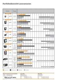
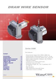
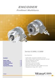
ENCODER Incremental A36/A58
- Incremental output Linedriver L (RS422, TTL), or Push-Pull G - Housing diameter 36 mm or 58 mm - Solid shaft, hollow shaft and through hollow shaft - Protection class IP64, solid shaft version also IP67 - Temperature range up to -20...+85 °C - Output frequency up to 300 kHz - Rotation speed up to 12.000 r/min - Aluminium housing - Customised versions available
- Incremental output Linedriver L (RS422, TTL),
or Push-Pull G
- Housing diameter 36 mm or 58 mm
- Solid shaft, hollow shaft and through hollow shaft
- Protection class IP64, solid shaft version also IP67
- Temperature range up to -20...+85 °C
- Output frequency up to 300 kHz
- Rotation speed up to 12.000 r/min
-
Aluminium housing
-
Customised versions available

Create successful ePaper yourself
Turn your PDF publications into a flip-book with our unique Google optimized e-Paper software.
- 6 -<br />
ELECTRICAL CONNECTION <strong>A36</strong>, <strong>A58</strong><br />
Signal 0 V +V 0 V sens<br />
* +V sens<br />
* A A Not B B Not Z Z Not screen<br />
Connector M23, 12-pole 10 12 11 2 5 6 8 1 3 4 housing<br />
Connector M12, 8-pole 1 2 - - 3 4 5 6 7 8 housing<br />
Cable output white brown black violet green yellow grey pink blue red housing<br />
* For Linedriver L only. For long cable lengths it may occur that the operating voltage at the sensor does not suffice due to the output resistance. With the sensor lines<br />
0 V sens and +V sens the operating voltage can be checked and, if necessary, be readjusted at the input connection.<br />
+V: Encoder power supply +VDC A, A Not : <strong>Incremental</strong> output channel A<br />
0 V: Encoder power supply ground GND (0 V) B, B Not : <strong>Incremental</strong> output channel B<br />
0 V sens / +V sens : Using the sensor outputs of the encoder, the voltage Z, Z Not : Reference signal<br />
present can be measured and if necessary increased accordingly<br />
Connector output M23, 12 poles<br />
(only for <strong>A58</strong>)<br />
Connector output M12, 8 poles<br />
Cable output<br />
Cable type<br />
PVC, flexible<br />
Cable direction<br />
radial or axial<br />
Length<br />
2.0 m<br />
Diameter<br />
ø 4.5 mm<br />
Wires<br />
8 (push-pull) and 10 (linedriver) x 0.14 mm²<br />
Temperature fixed installation -30...+85 °C<br />
flexible installation -20...+85 °C<br />
Assignment<br />
see table above<br />
ELECTRICAL DATA <strong>A36</strong>, <strong>A58</strong><br />
Electrical Data<br />
Linedriver L<br />
Push Pull G<br />
RS422 (TTL compatible)<br />
Power supply [VDC] 5, ±5 % 8...30<br />
Current consumption without load<br />
[mA]<br />
typ. 40, max. 90 typ. 40, max. 100<br />
Load / channel <strong>A36</strong><br />
[mA]<br />
max. ±20 max. ±20<br />
Load / channel <strong>A58</strong><br />
[mA]<br />
max. ±20 max. ±40<br />
Pulse frequency <strong>A36</strong><br />
[kHz]<br />
max. 300 max. 200<br />
Pulse frequency <strong>A58</strong><br />
[kHz]<br />
max. 300 max. 200<br />
Signal level high [V] min. 2.5 min. +V – 3<br />
Signal level low<br />
[V]<br />
max. 0.5 max. 0.5<br />
Sensor<br />
Circuit<br />
Sensor<br />
Circuit<br />
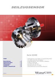
Recommended circuit<br />
+5 V<br />
A<br />
Z<br />
+5 V<br />
A<br />
R L<br />
+V = 8..30 V<br />
0 V<br />
Ā<br />
0 V<br />
Ā<br />
0 V<br />
Z = 120 Ohm<br />
R L<br />
= 1 kOhm<br />
.<br />
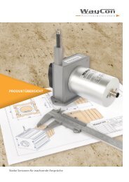
Output signal<br />
Pulses A and B are 90° phase-delayed (detection of direction). The Z-Pulse<br />
is emitted once per turn. The Z-Pulse can be used as a reference mark.<br />
The diagram shows the signal without inverted pulses<br />
A<br />
90° 360°<br />
B<br />
Z<br />
90°<br />
Z-Pulse with A/B<br />
AND-related<br />
Clockwise rotation - view onto shaft