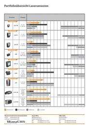
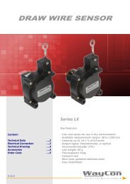
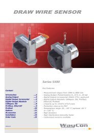
ENCODER Incremental A36/A58
- Incremental output Linedriver L (RS422, TTL), or Push-Pull G - Housing diameter 36 mm or 58 mm - Solid shaft, hollow shaft and through hollow shaft - Protection class IP64, solid shaft version also IP67 - Temperature range up to -20...+85 °C - Output frequency up to 300 kHz - Rotation speed up to 12.000 r/min - Aluminium housing - Customised versions available
- Incremental output Linedriver L (RS422, TTL),
or Push-Pull G
- Housing diameter 36 mm or 58 mm
- Solid shaft, hollow shaft and through hollow shaft
- Protection class IP64, solid shaft version also IP67
- Temperature range up to -20...+85 °C
- Output frequency up to 300 kHz
- Rotation speed up to 12.000 r/min
-
Aluminium housing
-
Customised versions available

You also want an ePaper? Increase the reach of your titles
YUMPU automatically turns print PDFs into web optimized ePapers that Google loves.
<strong>ENCODER</strong><br />
<strong>Incremental</strong> Angle Transducer<br />
Series <strong>A36</strong>, <strong>A58</strong><br />
Key-Features:<br />
Content:<br />
Technical Data <strong>A36</strong> ....2<br />
Technical Data <strong>A58</strong> ....4<br />
Elektrical Data ....6<br />
Accessories ....7<br />
Measuring Wheels ....8<br />
Order Code ....9<br />
- <strong>Incremental</strong> output Linedriver L (RS422, TTL),<br />
or Push-Pull G<br />
- Housing diameter 36 mm or 58 mm<br />
- Solid shaft, hollow shaft and through hollow shaft<br />
- Protection class IP64, solid shaft version also IP67<br />
- Temperature range up to -20...+85 °C<br />
- Output frequency up to 300 kHz<br />
- Rotation speed up to 12.000 r/min<br />
- Aluminium housing<br />
- Customised versions available<br />
17.12.14
- 2 -<br />
TECHNICAL DATA <strong>A36</strong><br />
Solid shaft<br />
Hollow shaft / Through hollow shaft<br />
Shaft diameter D [mm] 6 6 / 6.35 / 8 (depth of hollow shaft = 2 x D)<br />
Selectable resolution * [pulses/turn] 25 / 100 / 125 / 200 / 250 / 300 / 360 / 500 / 1000 / 1024 / 1250 / 1500 / 2000 / 2048 / 2500 / 3600<br />
<strong>A36</strong><br />
Sensor element<br />
Output signal<br />
<strong>Incremental</strong>-Encoder (with optical code disk)<br />
A/B-Pulses (90° phase-delayed), Z-Pulse (plus inverted pulses A not , B not , Z not )<br />
Electrical data see page 6<br />
Maximum rotation speed [r/min]<br />
12.000 6000<br />
Maximum shaft load [N] radial 40, axial 20 radial 40, axial 20<br />
Moment of inertia<br />
Starting torque at 20°C<br />
[kgm²]<br />
[Nm]<br />
0,2x10 -6<br />
- 3 -<br />
TECHNICAL DRAWING <strong>A36</strong><br />
Solid shaft, connector output axial<br />
Hollow shaft / Through hollow shaft, cable output radial<br />
Through hollow shaft, cable output axial
- 4 -<br />
TECHNICAL DATA <strong>A58</strong><br />
Solid shaft<br />
Hollow shaft / Through hollow shaft<br />
Shaft diameter D [mm] 6 / 10 / 12 12 / 20 / 25 / 28<br />
Selectable resolution * [pulses/turn] 60 / 100 / 125 / 200 / 250 / 400 / 500 / 960 / 1000 / 1024 / 2000 / 2048 / 5000<br />
<strong>A58</strong><br />
Sensor element<br />
Output signal<br />
<strong>Incremental</strong>-Encoder (with optical code disk)<br />
A/B-Pulses (90° phase-delayed), Z-Pulse (plus inverted pulses A not , B not , Z not )<br />
Electrical data see page 6<br />
Maximum rotation speed [r/min]<br />
12.000 2500<br />
Maximum shaft load [N] radial 40, axial 60 radial 60, axial 80<br />
Moment of inertia<br />
Starting torque at 20°C<br />
[kgm²]<br />
[Nm]<br />
1,4x10 -6<br />
- 5 -<br />
TECHNICAL DRAWING <strong>A58</strong><br />
Solid shaft, cable output radial<br />
Solid shaft, cable output axial<br />
Synchro flange (measurements for connector and cable output please see versions with solid shaft)<br />
Through hollow shaft, connector output radial M23, 12 poles<br />
(measurements for connector output radial M12, 8 poles, see page 4)<br />
Through hollow through shaft, cable output radial
- 6 -<br />
ELECTRICAL CONNECTION <strong>A36</strong>, <strong>A58</strong><br />
Signal 0 V +V 0 V sens<br />
* +V sens<br />
* A A Not B B Not Z Z Not screen<br />
Connector M23, 12-pole 10 12 11 2 5 6 8 1 3 4 housing<br />
Connector M12, 8-pole 1 2 - - 3 4 5 6 7 8 housing<br />
Cable output white brown black violet green yellow grey pink blue red housing<br />
* For Linedriver L only. For long cable lengths it may occur that the operating voltage at the sensor does not suffice due to the output resistance. With the sensor lines<br />
0 V sens and +V sens the operating voltage can be checked and, if necessary, be readjusted at the input connection.<br />
+V: Encoder power supply +VDC A, A Not : <strong>Incremental</strong> output channel A<br />
0 V: Encoder power supply ground GND (0 V) B, B Not : <strong>Incremental</strong> output channel B<br />
0 V sens / +V sens : Using the sensor outputs of the encoder, the voltage Z, Z Not : Reference signal<br />
present can be measured and if necessary increased accordingly<br />
Connector output M23, 12 poles<br />
(only for <strong>A58</strong>)<br />
Connector output M12, 8 poles<br />
Cable output<br />
Cable type<br />
PVC, flexible<br />
Cable direction<br />
radial or axial<br />
Length<br />
2.0 m<br />
Diameter<br />
ø 4.5 mm<br />
Wires<br />
8 (push-pull) and 10 (linedriver) x 0.14 mm²<br />
Temperature fixed installation -30...+85 °C<br />
flexible installation -20...+85 °C<br />
Assignment<br />
see table above<br />
ELECTRICAL DATA <strong>A36</strong>, <strong>A58</strong><br />
Electrical Data<br />
Linedriver L<br />
Push Pull G<br />
RS422 (TTL compatible)<br />
Power supply [VDC] 5, ±5 % 8...30<br />
Current consumption without load<br />
[mA]<br />
typ. 40, max. 90 typ. 40, max. 100<br />
Load / channel <strong>A36</strong><br />
[mA]<br />
max. ±20 max. ±20<br />
Load / channel <strong>A58</strong><br />
[mA]<br />
max. ±20 max. ±40<br />
Pulse frequency <strong>A36</strong><br />
[kHz]<br />
max. 300 max. 200<br />
Pulse frequency <strong>A58</strong><br />
[kHz]<br />
max. 300 max. 200<br />
Signal level high [V] min. 2.5 min. +V – 3<br />
Signal level low<br />
[V]<br />
max. 0.5 max. 0.5<br />
Sensor<br />
Circuit<br />
Sensor<br />
Circuit<br />
Recommended circuit<br />
+5 V<br />
A<br />
Z<br />
+5 V<br />
A<br />
R L<br />
+V = 8..30 V<br />
0 V<br />
Ā<br />
0 V<br />
Ā<br />
0 V<br />
Z = 120 Ohm<br />
R L<br />
= 1 kOhm<br />
.<br />
Output signal<br />
Pulses A and B are 90° phase-delayed (detection of direction). The Z-Pulse<br />
is emitted once per turn. The Z-Pulse can be used as a reference mark.<br />
The diagram shows the signal without inverted pulses<br />
A<br />
90° 360°<br />
B<br />
Z<br />
90°<br />
Z-Pulse with A/B<br />
AND-related<br />
Clockwise rotation - view onto shaft
- 7 -<br />
ACCESSORIES<br />
Cable with connector M12, 8 poles, shielded<br />
K8P2M-S-M12<br />
2 m, connector straight<br />
K8P5M-S-M12<br />
5 m, connector straight<br />
K8P10M-S-M12 10 m, connector straight<br />
K8P2M-SW-M12 2 m, connector angular<br />
K8P5M-SW-M12 5 m, connector angular<br />
K8P10M-SW-M12 10 m, connector angular<br />
Cable with connector M23, 8 poles, shielded<br />
K8P2M-S-M23<br />
2 m, connector straight<br />
K8P5M-S-M23<br />
5 m, connector straight<br />
K8P10M-S-M23 10 m, connector straight<br />
K8P...-M12<br />
D8-W/G-M12-S<br />
Mating connector M12, 8 poles, shielded<br />
D8-G-M12-S mating connector straight<br />
D8-W-M12-S mating connector angular<br />
protection class: IP67<br />
temperature: -25...+90 °C<br />
cable passage: ø 4...8 mm<br />
wire diameter: 0.14...0.34 mm²<br />
mode of connection: spring cage<br />
Mating connector M23, 12 poles<br />
CON012-S straight, metal housing<br />
wire diameter: AWG 16...26 mm²<br />
cable diameter: ø 5.5...10 mm<br />
CON012-S<br />
Couplings<br />
Bellows couplings are used for the free of backlash connection between an encoder and a shaft. The couplings are free<br />
of wear and compensate lateral, axial and angular shaft misalignment. The mounting on the shaft is done by clamping<br />
hubs.<br />
The following bellow couplings are usually on stock:<br />
MBK-15.5-23-06-06 MBK-20-26-06-10 MBK-20-26-10-10<br />
Mounting by clamping excentics<br />
The <strong>A36</strong> and <strong>A58</strong> encoder can be mounted with these excentrics.<br />
The BX36 and BX58 kits include 3 excentrics and 3 screws.<br />
Required drill holes:<br />
BX36: M2.5-screw thread, depth 5 mm, ø screw-hole circle 42 mm<br />
BX58: M3-screw thread, depth 6 mm, ø screw-hole circle 65 mm<br />
Digital distance and speed display - WAY-D for incremental output signals<br />
Use the WAY-D display to visualise the measured distance or the speed (tachometer) of the position transducer. A<br />
transfer of data to a PC or PLC can be done with the RS232 interface of the WAY-DR.<br />
Protection class:<br />
Display:<br />
Supply:<br />
IP65 (front panel)<br />
6 digits<br />
115 / 250 VAC<br />
Output Linedriver L (TTL, RS422):<br />
WAY-DS-5VH:<br />
display only, input level TTL<br />
WAY-DG-5VH:<br />
display with two presets and switching outputs, input level TTL<br />
WAY-DR-5VH:<br />
display with serial interface RS232 / RS485, input level TTL<br />
Output Push-Pull G:<br />
WAY-DS:<br />
WAY-DG:<br />
WAY-DR:<br />
display only, input level HTL<br />
display with two presets and switching outputs, input level HTL<br />
display with serial interface RS232 / RS485, input level HTL<br />
For further information please see the WAY-D data sheet.
- 8 -<br />
MEASURING WHEELS<br />
Measuring wheels for measuring the length of products in movement, e.g. in the paper, metal, textile, wood or plastic industry.<br />
Material of wheel body: aluminium<br />
Temperature range: -30...80°C<br />
Surface of the measured<br />
Recommended<br />
material<br />
Profile<br />
Cardboard 1, 2, 3, 4, 5<br />
Wood 1, 2, 3, 4, 5<br />
Textile 1, 2, 3, 4<br />
Plastics (e.g. PVC, PE,..) 2, 3, 4, 5<br />
Paper 2, 3, 4, 5<br />
Wire, greased metals, steel profiles, leather 2<br />
Carpet, cables, nonwoven<br />
3<br />
Greased metals, glass, floor coverings 4<br />
Painted surfaces 2, 4<br />
Rubber, soft plastic 1<br />
Measuring Wheel Profile Coating Weight Bore Order Code<br />
Circumference / Ø / Width Measuring Wheel<br />
1 diamond knurl (aluminium) 60 g 10 mm MSR-02-1<br />
0.2 m / Ø 63.7 mm / 12 mm<br />
2 plastic (polyurethane) smooth 60 g (6 mm MSR-02-2<br />
3 tufted rubber (polyurethane) 60 g on MSR-02-3<br />
4 plastic (polyurethane) corrugated 60 g request) MSR-02-4<br />
1 diamond knurl (aluminium) 775 g<br />
MSR-05-1<br />
0.5 m / Ø 159.2 mm / 25 mm<br />
2 plastic (polyurethane) smooth 700 g<br />
10 mm<br />
MSR-05-2<br />
3 tufted rubber (polyurethane) 700 g MSR-05-3<br />
4 plastic (polyurethane) corrugated 700 g MSR-05-4<br />
12“ / Ø 3.82“ / 0.38“<br />
5 natural rubber (NR) smooth 100 g 10 mm MSR-12-5<br />
SPRING <strong>ENCODER</strong> ARM<br />
• Spring encoder arm for easy mounting of a measuring wheel with Encoder<br />
• Flexible mounting position: 9 setting positions in 40° steps<br />
• Base plate, variable in 4 directions<br />
• Adjustable spring pressure, max. 40 N<br />
• Pressure for each notch approx. 20 N (first notch between<br />
0 and approx. 20 N)<br />
• Temperature range -40...120°C
- 9 -<br />
ORDER CODE <strong>A36</strong><br />
<strong>A36</strong><br />
Shaft Version<br />
Solid shaft<br />
Through hollow shaft<br />
Hollow shaft<br />
W<br />
H<br />
SH<br />
-<br />
IP67<br />
Protection Class<br />
Standard IP64<br />
IP67 (only for solid shaft versions)<br />
Shaft diameter [mm]<br />
Solid shaft: 6<br />
Through hollow shaft: 6 / 6.35 / 8<br />
Hollow shaft: 6 / 6.35 / 8<br />
6<br />
KA<br />
KR<br />
SR<br />
SA<br />
Connection<br />
Cable output axial 1 , 2<br />
Cable output radial<br />
Connector output M12 radial<br />
Connector output M12 axial 1 , 2<br />
1 not available for through hollow shaft<br />
Output<br />
Linedriver L (RS422, TTL)<br />
Push-Pull G<br />
L<br />
G<br />
2 for Linedriver: 10 wires (with additional sensor lines)<br />
for Push-Pull: 8 wires (without additional sensor lines)<br />
Resolution [Pulses/turn]<br />
25 / 100 / 200 / 360 / 500 / 1000 / 1024 /<br />
1500 / 2000 / 2048 / 2500 / 3600<br />
ORDER CODE <strong>A58</strong><br />
<strong>A58</strong><br />
Shaft Version<br />
Solid shaft (with clamping flange)<br />
Solid shaft (with Synchro flange)<br />
Hollow shaft<br />
W<br />
WY<br />
H<br />
-<br />
IP67<br />
Protection Class<br />
Standard IP64<br />
IP67 (only for solid shaft versions)<br />
Shaft diameter [mm]<br />
Solid shaft (with clamping flange): 6 / 10 / 12<br />
Solid shaft (with Synchro flange): 6<br />
Through hollow shaft: 12 / 20 / 24 / 25 / 28<br />
Output<br />
6<br />
KA<br />
KR<br />
SR<br />
SA<br />
SRM12<br />
SAM12<br />
Connection<br />
Cable output axial (not for hollow shaft) *<br />
Cable output radial *<br />
Connector output M23 radial<br />
Connector output M23 axial (not for hollow shaft)<br />
Connector output M12 radial<br />
Connector output M12 axial (not for hollow shaft)<br />
Linedriver L (RS422, TTL)<br />
Push-Pull G<br />
L<br />
G<br />
* for Linedriver: 10 wires (with additional sensor lines)<br />
for Push-Pull: 8 wires (without additional sensor lines)<br />
Resolution [Pulses/turn]<br />
60 / 100 / 200 / 250 / 400 / 500 / 960 / 1000 /<br />
1024 / 2000 / 5000
- 10 -<br />
ACCESSORIES<br />
Cable with connector M12, 8 poles, shielded<br />
Clamping excentric kit<br />
K8P2M-S-M12 2 m, straight connector BX36<br />
for <strong>A36</strong>, the kit includes 3 excentrics and 3 screws<br />
K8P5M-S-M12 5 m, straight connector BX58<br />
for <strong>A58</strong>, the kit includes 3 excentrics and 3 screws<br />
K8P10M-S-M12<br />
K8P2M-SW-M12<br />
K8P5M-SW-M12<br />
10 m, straight connector<br />
2 m, angular connector<br />
5 m, angular connector<br />
Couplings<br />
MBK-15.5-23-06-06 coupling, bore diameter: 2 x ø 6 mm<br />
K8P10M-SW-M12 10 m, angular connector MBK-20-26-06-10<br />
MBK-20-26-10-10<br />
coupling, bore diameter: ø 6 mm, ø 10 mm<br />
coupling, bore diameter: 2 x ø 10 mm<br />
Cable with connector M23, 8 poles, shielded<br />
K8P2M-S-M23<br />
K8P5M-S-M23<br />
2 m, straight connector<br />
5 m, straight connector Digital display 1 channel, Linedriver L (input level TTL, RS422)<br />
K8P10M-S-M23 10 m, straight connector<br />
WAY-DS-5VH display only<br />
WAY-DG-5VH display with two presets and switching outputs<br />
Mating Connector M23, 12 poles, shielded WAY-DR-5VH display with serial interface RS232 / RS485<br />
CON012-S<br />
straight, M23 for self assembly, metal housing<br />
Mating Connector M12, 8 poles, shielded<br />
Digital display 1 channel, Push-Pull G<br />
D8-G-M12-S straight, M12 for self assembly<br />
WAY-DS display only<br />
D8-W-M12-S angular, M12 for self assembly<br />
WAY-DG<br />
WAY-DR<br />
display with two presets and switching outputs<br />
display with serial interface RS232 / RS485<br />
Extended cable for cable output (2m is standard)<br />
Kabel-PVC-36<br />
Kabel-PVC-58<br />
1 for each additional meter (for series <strong>A36</strong>)<br />
1 for each additional meter (for series <strong>A58</strong>)<br />
Subject to change without prior notice.<br />
WayCon Positionsmesstechnik GmbH<br />
email: info@waycon.de<br />
internet: www.waycon.de<br />
Head Office<br />
Mehlbeerenstr. 4<br />
82024 Taufkirchen<br />
Tel. +49 (0)89 67 97 13-0<br />
Fax +49 (0)89 67 97 13-250<br />
Office Köln<br />
Auf der Pehle 1<br />
50321 Brühl<br />
Tel. +49 (0)2232 56 79 44<br />
Fax +49 (0)2232 56 79 45