
Create successful ePaper yourself
Turn your PDF publications into a flip-book with our unique Google optimized e-Paper software.
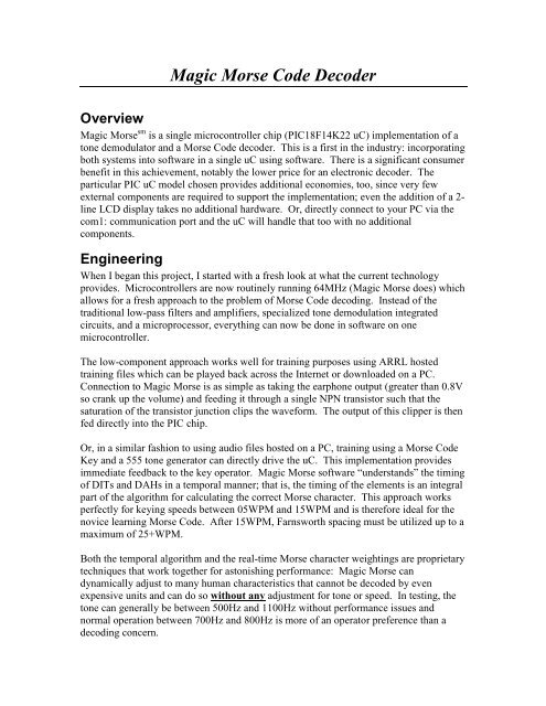
<strong>Magic</strong> <strong>Morse</strong> <strong>Code</strong> <strong>Decoder</strong><br />
Overview<br />
<strong>Magic</strong> <strong>Morse</strong> sm is a single microcontroller chip (PIC18F14K22 uC) implementation of a<br />
tone demodulator and a <strong>Morse</strong> <strong>Code</strong> decoder. This is a first in the industry: incorporating<br />
both systems into software in a single uC using software. There is a significant consumer<br />
benefit in this achievement, notably the lower price for an electronic decoder. The<br />
particular PIC uC model chosen provides additional economies, too, since very few<br />
external components are required to support the implementation; even the addition of a 2line<br />
LCD display takes no additional hardware. Or, directly connect to your PC via the<br />
com1: communication port and the uC will handle that too with no additional<br />
components.<br />
Engineering<br />
When I began this project, I started with a fresh look at what the current technology<br />
provides. Microcontrollers are now routinely running 64MHz (<strong>Magic</strong> <strong>Morse</strong> does) which<br />
allows for a fresh approach to the problem of <strong>Morse</strong> <strong>Code</strong> decoding. Instead of the<br />
traditional low-pass filters and amplifiers, specialized tone demodulation integrated<br />
circuits, and a microprocessor, everything can now be done in software on one<br />
microcontroller.<br />
The low-component approach works well for training purposes using ARRL hosted<br />
training files which can be played back across the Internet or downloaded on a PC.<br />
Connection to <strong>Magic</strong> <strong>Morse</strong> is as simple as taking the earphone output (greater than 0.8V<br />
so crank up the volume) and feeding it through a single NPN transistor such that the<br />
saturation of the transistor junction clips the waveform. The output of this clipper is then<br />
fed directly into the PIC chip.<br />
Or, in a similar fashion to using audio files hosted on a PC, training using a <strong>Morse</strong> <strong>Code</strong><br />
Key and a 555 tone generator can directly drive the uC. This implementation provides<br />
immediate feedback to the key operator. <strong>Magic</strong> <strong>Morse</strong> software “understands” the timing<br />
of DITs and DAHs in a temporal manner; that is, the timing of the elements is an integral<br />
part of the algorithm for calculating the correct <strong>Morse</strong> character. This approach works<br />
perfectly for keying speeds between 05WPM and 15WPM and is therefore ideal for the<br />
novice learning <strong>Morse</strong> <strong>Code</strong>. After 15WPM, Farnsworth spacing must be utilized up to a<br />
maximum of 25+WPM.<br />
Both the temporal algorithm and the real-time <strong>Morse</strong> character weightings are proprietary<br />
techniques that work together for astonishing performance: <strong>Magic</strong> <strong>Morse</strong> can<br />
dynamically adjust to many human characteristics that cannot be decoded by even<br />
expensive units and can do so without any adjustment for tone or speed. In testing, the<br />
tone can generally be between 500Hz and 1100Hz without performance issues and<br />
normal operation between 700Hz and 800Hz is more of an operator preference than a<br />
decoding concern.
Performance<br />
How good can a single-chip solution really be? The answer surprised even me after the<br />
design and throughout the testing period. Using ARRL wave files for <strong>Morse</strong> <strong>Code</strong><br />
training, the circuit works without any fiddling (volume set once) from 05WPM to<br />
15WPM. JAVA software programs on the Internet with Farnsworth encoding can move<br />
the upper end of the decoding to over 25WPM. Lab testing with 100% accuracy has been<br />
accomplished from 6WPM to 29WPM – Please note that your results may vary<br />
significantly because of the PC electronics; distortion, noise, signal amplitude are all<br />
variables that cannot be qualified.<br />
uC and Optional 5V power Circuitry<br />
The digital circuit is simplicity and can be built on a breadboard or universal PC<br />
prototyping boards.
Audio Circuitry<br />
<strong>Magic</strong> <strong>Morse</strong> is a training aid for <strong>Morse</strong> <strong>Code</strong>. Therefore, lab testing has been limited to<br />
training files provided by the ARRL on their website and online training programs.<br />
Additionally, to assist with keying exercises, the output from the code practice oscillator<br />
can be applied to the clipper circuitry to drive <strong>Magic</strong> <strong>Morse</strong>. The preferred circuit is a<br />
single 555 phase lock loop which uses the same +5V supply as <strong>Magic</strong> <strong>Morse</strong>. The<br />
schematic can be found here: http://www.sentex.net/~mec1995/circ/morse1.htm<br />
This simple circuit performed superbly in the lab.<br />
What I have not tested is the use of <strong>Magic</strong> <strong>Morse</strong> with amateur communication receivers<br />
or shortwave radios. This is an area where Ham expertise in electronic assembly will<br />
certainly be required because a low-pass filter and narrow-band pass filter must be<br />
utilized to both isolate the specific code and to eliminate potential interference. After the<br />
filtering, it is most likely that the voltage will be under 0.8V and therefore not acceptable<br />
to drive the NPN clipper circuit and amplification will be required. Such circuitry is well<br />
discussed on the Internet and some Hams have made a small business from the design<br />
and selling of such hardware. There are links in the Appendix section for anyone<br />
interested but this is unchartered waters for <strong>Magic</strong> <strong>Morse</strong>.<br />
The audio “clipper” circuit used with <strong>Magic</strong> <strong>Morse</strong> is intended only for simple<br />
interfacing requirements: such as the earphone jack from a PC or the code practice<br />
oscillator. An earphone output must generate a minimum of 0.8V positive peak or<br />
higher. This voltage, fed to the base of the NPN transistor through a 2.2K to 150 Ohm<br />
resistor will cause the NPN to saturate and clip the lower (near 0V) audio signal. The<br />
output of the clipper is fed to the uC chip on Pin #11. The uC input pin idles at +5V.
After assembly of you <strong>Magic</strong> <strong>Morse</strong> <strong>Code</strong> <strong>Decoder</strong> on a suitable circuit or prototyping<br />
board, we suggest that you utilize the first site listed in the Web Resources section of the<br />
Appendix to become familiar with using the circuit and adjusting the volume feeding the<br />
clipper.<br />
<strong>Magic</strong> <strong>Morse</strong> supports 2 LEDs for visual output: Pin #15 and Pin #16. Both pins are<br />
“active high” which means that the uC provides +5V to a LED for the power on source.<br />
Pin #15 is active for “DAH” and Pin #16 is active for “DIT”.<br />
WARNING: you must supply at least a 200 ohm resistor for each LED to limit current.<br />
The only time the two LEDS are illuminated together is during the few seconds during<br />
initial power and software initialization of <strong>Magic</strong> <strong>Morse</strong>.<br />
Contact Us<br />
If you need to contact us or just want to let us know what you are doing with <strong>Magic</strong><br />
<strong>Morse</strong>, please send eMail to: magic.morse@gmail.com If your communication needs a<br />
response, please allow us 48 hours to research and create a return email. If you send in<br />
suggestions for feature designs or modifications, please understand that all submissions<br />
become our property if we elect to use them. This policy is just sensible since we may<br />
already be working on the enhancement or may have received a similar request from<br />
another customer. Each request will be analyzed for overall benefit to this product and<br />
some suggestions may not fit in our marketing or technical parameters.<br />
Thank you,<br />
Ray Burne<br />
<strong>Magic</strong> <strong>Morse</strong>
APPENDIX<br />
LCD INFO<br />
The uC is pre-programmed with formatting code to utilize 2-line by 16-character LCD<br />
displays. During testing, two brands were certified for commonly available 9600 BAUD<br />
(N,8,1) displays:<br />
http://www.sparkfun.com/products/9877 (Default)<br />
http://www.seetron.com/bpi216.html<br />
The two displays are significantly different in that the SparkFun display “idles high” and<br />
the Scott Edwards display “idles low”. Pin #3 on the uC can be grounded to change the<br />
default idle high to a idle low state required for the Seetron display or for connecting to a<br />
PC directly from Pin #19 of the uC (PC integrated 5V RS232 port Com1: or port Com2:<br />
expects an idle-low connection.)<br />
However, we do realize that you may already have a LCD display which is capable of<br />
directly interfacing via a serial interface to the <strong>Magic</strong> <strong>Morse</strong> <strong>Code</strong> <strong>Decoder</strong> uC. Some<br />
LCD displays may work without any software modifications if the display is 2-lines and<br />
has 16 or greater characters per line. The display will only show 16 characters, however,<br />
before switching to the beginning of the next line. Any LCD connected serially to <strong>Magic</strong><br />
<strong>Morse</strong> must be 9600 BAUD and support the “N,8,1” protocol. If you get “gibberish” turn<br />
off the power and reverse the state of Pin #3 (ground or open) and repower the unit. If<br />
neither options work and the display is 9600,N,8,1 then it is likely to assume the display<br />
is not compatible.<br />
Web Resources<br />
Listed below are Internet resources which you may find useful in designing and building<br />
a quality narrow-bandwidth audio frontend for the <strong>Magic</strong> <strong>Morse</strong> chip.<br />
http://morsecode.scphillips.com/jtranslator.html<br />
http://hamradio.cc/projects/<strong>Morse</strong>_<strong>Code</strong>_<strong>Decoder</strong>_Circuit.php<br />
http://www.qsl.net/dl4yhf/old_hamradio_stuff/index.html<br />
http://www.electronics-project-design.com/HamRadioCircuit.html<br />
http://kb1kix.net/blog/?cat=12<br />
http://www.qsl.net/k3pd/chap07.pdf (starting pg 15)<br />
http://www.rason.org/Projects/cwfilter/cwfilter.htm<br />
http://www.falstad.com/circuit/ (roll your own from scratch)