Crystal - cs5336.pdf
Crystal - cs5336.pdf
Crystal - cs5336.pdf

You also want an ePaper? Increase the reach of your titles
YUMPU automatically turns print PDFs into web optimized ePapers that Google loves.
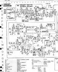
CS5336, CS5338, CS5339<br />
*<br />
L/ R<br />
Input<br />
SCLK<br />
Input<br />
0 1 2<br />
15 16 17 18 19 20 0 1 2 15 16 17 18 19 20<br />
FSYNC<br />
Input<br />
** *** **<br />
***<br />
SDATA<br />
Output<br />
15 15 14 1 0 T2 T1 T0 15 15 14 1 0 T2 T1 T0<br />
Left Audio Data Tag Bits Left Data Right Audio Data Tag Bits Right Data<br />
Tag<br />
Tag<br />
*<br />
SCLK for CS5336/8.<br />
**<br />
***<br />
Rising FSYNC enables<br />
SCLK inverted for CS5339<br />
SCLK to clock out SDATA<br />
Falling FSYNC stops SCLK from<br />
clocking out SDATA<br />
Figure 5. Data Output Timing - SLAVE Mode, FSYNC controlled<br />
output each bit, except the MSB, which is clocked<br />
out by the L/R edge. As shown in Figure 4, when<br />
FSYNC is high, serial data bits are clocked immediately<br />
following the L/R edge.<br />
In SLAVE mode with FSYNC controlled, as<br />
shown in Figure 5, when FSYNC is low, only the<br />
MSB is clocked out after the L/R edge. With<br />
FSYNC low, SCLK is ignored. When it is desired<br />
to start clocking out data, bring FSYNC high<br />
which enables SCLK to start clocking out data.<br />
Bringing FSYNC low will stop the data being<br />
clocked out. This feature is particularly useful to<br />
Input Level T2 T1 T0<br />
1.375 x FS 1 1 1<br />
1.250 x FS to 1.375 x FS 1 1 0<br />
1.125 x FS to 1.250 x FS 1 0 1<br />
1.000 x FS to 1.125 x FS 1 0 0<br />
-1.006dB to 0.000dB 0 1 1<br />
-3.060dB to -1.006dB 0 1 0<br />
-6.000dB to -3.060dB 0 0 1<br />
< -6.000dB 0 0 0<br />
FS = Full Scale (0dB) Input<br />
position in time the data bits onto a common serial<br />
bus.<br />
The serial nature of the output data results in the<br />
left and right data words being read at different<br />
times. However, the words within an L/R cycle<br />
represent simultaneously sampled analog inputs.<br />
In all modes, additional bits are output after the<br />
data bits: 3 tag bits and a left/right indicator. The<br />
tag bits indicate a near-to-clipping input condition<br />
for the data word to which the tag bits are attached.<br />
Table 2 shows the relationship between<br />
input level and the tag bit values. The serial bit<br />
immediately following the tag bits is 0 for the<br />
left channel, and 1 for the right channel. The remaining<br />
bits before the next L/R edge will be 1’s<br />
for the left channel and 0’s for the right channel.<br />
Normally, the tag bits are separated from the<br />
audio data by the digital signal processor. However,<br />
if the tag bits are interpreted as audio data,<br />
their position below the LSB would result as a<br />
very small dc offset.<br />
In all modes, SCLK is shown for the CS5336 and<br />
CS5338, where data bits are clocked out on rising<br />
edges. SCLK is inverted for the CS5339.<br />
Table 2. Tag Bit Definition<br />
DS23F1 3-47