Crystal - cs5336.pdf
Crystal - cs5336.pdf
Crystal - cs5336.pdf

You also want an ePaper? Increase the reach of your titles
YUMPU automatically turns print PDFs into web optimized ePapers that Google loves.
CS5336, CS5338, CS5339<br />
L/ R<br />
Output<br />
* SCLK<br />
Output<br />
0 1 2 3 16 17 18 19 20 21 31 0 1 2 3 16 17 18 19 20 21 31 0 1<br />
FSYNC<br />
Output<br />
SDATA<br />
Output<br />
15 14 1 0 T2 T1 T0 15 14 1 0 T2 T1 T0<br />
* SCLK for CS5336/8.<br />
SCLK inverted for<br />
CS5339<br />
Left Audio Data Tag Bits Left Data Tag Right Audio Data Tag Bits Right Data Tag<br />
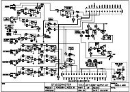
Figure 3. Data Output Timing - MASTER mode<br />
L/ R<br />
Input<br />
* SCLK<br />
Input<br />
0 1 2 15 16 17 18 19 20 30 31 0 1 2 15 16 17 18 19 20 21 31 0 1<br />
FSYNC<br />
Input (high)<br />
SDATA<br />
Output<br />
15 14 1 0 T2 T1 T0 15 14 1 0 T2 T1 T0<br />
* SCLK for CS5336/8.<br />
SCLK inverted for<br />
CS5339<br />
Left Audio Data Tag Bits Left Data Tag Right Audio Data Tag Bits Right Data Tag<br />
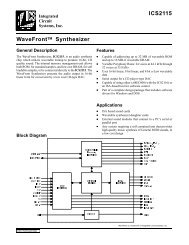
Figure 4. Data Output Timing - SLAVE Mode, FSYNC high<br />
low, ICLKD is divided by 2 to generate OCLKD.<br />
The phase relationship between ICLKD and<br />
OCLKD is always the same, and is shown in the<br />
Switching Characteristics Timing Diagrams.<br />
When CMODE is high, OCLKD is ICLKD divided<br />
by 3. There are two possible phase<br />
relationships between ICLKD and OCLKD,<br />
which depend on the start-up timing between<br />
DPD and L/R, shown in Figure 2.<br />
Serial Data Interface<br />
The serial data output interface has 3 possible<br />
modes of operation: MASTER mode, SLAVE<br />
mode with FSYNC high, and SLAVE mode with<br />
FSYNC controlled. In MASTER mode, the A/D<br />
converter is driven from a master clock (ICLKD)<br />
and outputs all other clocks, derived from ICLKD<br />
(see Figure 3). Notice the one SCLK cycle delay<br />
between L/R edges and FSYNC rising edges.<br />
FSYNC brackets the 16 data bits for each channel.<br />
In SLAVE mode, L/R and SCLK are inputs. L/R<br />
must be externally derived from ICLKD, and<br />
should be equal to the Output Word Rate. SCLK<br />
should be equal to the input sample rate, which is<br />
equal to OCLKD/2. Other SCLK frequencies are<br />
possible, but may degrade dynamic range because<br />
of interference effects. Data bits are clocked out<br />
via the SDATA pin using the SCLK and L/R inputs.<br />
The rising edge of SCLK causes the ADC to<br />
3-46 DS23F1