Crystal - cs5336.pdf
Crystal - cs5336.pdf
Crystal - cs5336.pdf

You also want an ePaper? Increase the reach of your titles
YUMPU automatically turns print PDFs into web optimized ePapers that Google loves.
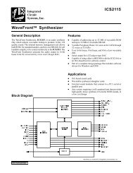
CS5336, CS5338, CS5339<br />
GENERAL DESCRIPTION<br />
The CS5336, CS5338, and CS5339 are 16-bit, 2-<br />
channel A/D converters designed specifically for<br />
stereo digital audio applications. The devices use<br />
two one-bit delta-sigma modulators which simultaneously<br />
sample the analog input signals at a 64<br />
X sampling rate. The resulting serial bit streams<br />
are digitally filtered, yielding pairs of 16-bit values.<br />
This technique yields nearly ideal conversion<br />
performance independent of input frequency and<br />
amplitude. The converters do not require difficultto-design<br />
or expensive anti-alias filters, and do not<br />
require external sample-and-hold amplifiers or a<br />
voltage reference.<br />
An on-chip voltage reference provides for an input<br />
signal range of ± 3.68 volts. Any zero offset is<br />
internally calibrated out during a power-up selfcalibration<br />
cycle. Output data is available in serial<br />
form, coded as 2’s complement 16-bit numbers.<br />
Typical power consumption of only 400 mW can<br />
be further reduced by use of the power-down<br />
mode.<br />
For more information on delta-sigma modulation<br />
and the particular implementation inside these<br />
ADCs, see the references at the end of this data<br />
sheet.<br />
OCLKD/<br />
L/R CMODE ICLKD ICLKA SCLK<br />
(kHz) (MHz) (MHz) (MHz)<br />
32 low 8.192 4.096 2.048<br />
32 high 12.288 4.096 2.048<br />
44.1 low 11.2896 5.6448 2.8224<br />
44.1 high 16.9344 5.6448 2.8224<br />
48 low 12.288 6.144 3.072<br />
48 high 18.432 6.144 3.072<br />
Table 1. Common Clock Frequencies<br />
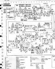
SYSTEM DESIGN<br />
Very few external components are required to support<br />
the ADC. Normal power supply decoupling<br />
components, voltage reference bypass capacitors<br />
and a single resistor and capacitor on each input<br />
for anti-aliasing are all that’s required, as shown<br />
in Figure 1.<br />
Master Clock Input<br />
The master input clock (ICLKD) into the ADC<br />
runs the digital filter, and is used to generate the<br />
modulator sampling clock. ICLKD frequency is<br />
determined by the desired Output Word Rate<br />
(OWR) and the setting of the CMODE pin.<br />
CMODE high will set the required ICLKD frequency<br />
to 384 X OWR, while CMODE low will<br />
set the required ICLKD frequency to 256 X<br />
OWR. Table 1 shows some common clock frequencies.<br />
The digital output clock (OCLKD) is<br />
always equal to 128 X OWR, which is always<br />
2 X the input sample rate. OCLKD should be<br />
connected to ICLKA, which controls the input<br />
sample rate.<br />
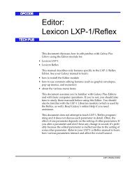
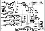
The phase alignment between ICLKD and<br />
OCLKD is determined as follows: when CMODE is<br />
ICLKD<br />
Input<br />
DPD<br />
Input<br />
_<br />
L/ R<br />
Input<br />
OCLKD<br />
Output<br />
_<br />
L/ R<br />
Input<br />
OCLKD<br />
Output<br />
1<br />
1<br />
2<br />
2<br />
*<br />
**<br />
0 1 2 3 4 5 6 7<br />
***<br />
* DPD low is recognized on the next ICLKD rising edge (#0)<br />
** L/R rising before ICLKD rising #2 causes OCLKD -1<br />
*** L/R rising after ICLKD rising #2 causes OCLKD - 2<br />
Figure 2. ICLKD to OCLKD Timing with CMODE<br />
high (384 X OWR)<br />
DS23F1 3-45