Crystal - cs5336.pdf
Crystal - cs5336.pdf
Crystal - cs5336.pdf

Create successful ePaper yourself
Turn your PDF publications into a flip-book with our unique Google optimized e-Paper software.
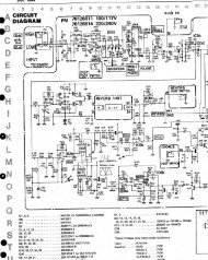
CS5336, CS5338, CS5339<br />
ZEROL, ZEROR - Zero Level Inputs for Left and Right Channels, PINS 3, 26.<br />
Analog zero level inputs for the left and right channels. The levels present on these pins<br />
can be used as zero during the offset calibration cycle. Normally connected to AGND,<br />
optionally through networks matched to the analog input networks.<br />
Analog Outputs<br />
VREF - Voltage Reference Output, PIN 28.<br />
Nominally -3.68 volts. Normally connected to a 0.1µF ceramic capacitor in parallel with a<br />
10µF or larger electrolytic capacitor. Note the negative output polarity.<br />
Digital Inputs<br />
ICLKA - Analog Section Input Clock, PIN 23.<br />
This clock is internally divided by 2 to set the modulators’ sample rate. Sampling rates,<br />
output rates, and digital filter characteristics scale to ICLKA frequency. ICLKA frequency<br />
is 128 X the output word rate. For example, 6.144 MHz ICLKA corresponds to an output<br />
word rate of 48 kHz per channel. Normally connected to OCLKD.<br />
ICLKD - Digital Section Input Clock, PIN 20.<br />
This is the clock which runs the digital filter. ICLKD frequency is determined by the<br />
required output word rate and by the CMODE pin. If CMODE is low, ICLKD frequency<br />
should be 256 X the desired output word rate. If CMODE is high, ICLKD should be<br />
384 X the desired output word rate. For example, with CMODE low, ICLKD should be<br />
12.288 MHz for an output word rate of 48 kHz. This clock also generates OCLKD,<br />
which is always 128 X the output word rate.<br />
APD - Analog Power Down, PIN 6.<br />
Analog section power-down command. When high, the analog circuitry is in power-down<br />
mode. APD is normally connected to DPD when using the power down feature. If power<br />
down is not used, then connect APD to AGND.<br />
DPD - Digital Power Down, PIN 10<br />
Digital section power-down command. Bringing DPD high puts the digital section into<br />
power-down mode. Upon returning low, the ADC starts an offset calibration cycle. This<br />
takes 4096 L/R periods (85.33 ms with a 12.288 MHz ICLKD). DCAL is high during the<br />
calibrate cycle and goes low upon completion. DPD is normally connected to APD when<br />
using the power down feature. A calibration cycle should always be initiated after<br />
applying power to the supply pins.<br />
ACAL - Analog Calibrate, PIN 7.<br />
Analog section calibration command. When high, causes the left and right channel<br />
modulator inputs to be internally connected to ZEROL and ZEROR inputs respectively.<br />
May be connected to DCAL.<br />
DS23F1 3-55