Crystal - cs5336.pdf
Crystal - cs5336.pdf
Crystal - cs5336.pdf

Create successful ePaper yourself
Turn your PDF publications into a flip-book with our unique Google optimized e-Paper software.
CS5336, CS5338, CS5339<br />
Certain serial modes align well with various interface<br />
requirements. A CS5339 in MASTER mode,<br />
with an inverted L/R signal, generates I 2 S<br />
(Philips) compatible timing. A CS5336 in MAS-<br />
TER mode, using FSYNC, interfaces well with a<br />
Motorola DSP56000. A CS5336 in SLAVE mode<br />
emulates a CS5326 style interface, and also links<br />
up to a DSP56000 in network mode.<br />
Analog Connections<br />
The analog inputs are presented to the modulators<br />
via the AINR and AINL pins. The analog input<br />
signal range is determined by the internal voltage<br />
reference value, which is typically -3.68 volts.<br />
The input signal range therefore is typically<br />
± 3.68 volts.<br />
The ADC samples the analog inputs at<br />
3.072 MHz for a 12.288 MHz ICLKD (CMODE<br />
low). For the CS5336, the digital filter rejects all<br />
noise between 26 kHz and (3.072 MHz-26 kHz).<br />
For the CS5338 and CS5339, the digital filter rejects<br />
all noise between 28 kHz and<br />
(3.072 MHz-28 kHz). However, the filter will not<br />
reject frequencies right around 3.072 MHz (and<br />
multiples of 3.072 MHz). Most audio signals do<br />
not have significant energy at 3.072 MHz. Nevertheless,<br />
a 51 Ω resistor in series with the analog<br />
input, and a 10 nF NPO or COG capacitor to<br />
ground will attenuate any noise energy at 3.072<br />
MHz, in addition to providing the optimum<br />
source impedance for the modulators. The use of<br />
capacitors which have a large voltage coefficient<br />
(such as general purpose ceramics) should be<br />
avoided since these can degrade signal linearity. If<br />
active circuitry precedes the ADC, it is recommended<br />
that the above RC filter is placed between<br />
the active circuitry and the AINR and AINL pins.<br />
The above example frequencies scale linearly with<br />
output word rate.<br />
The on-chip voltage reference output is brought<br />
out to the VREF pin. A 10 µF electrolytic capacitor<br />
in parallel with a 0.1 µF ceramic capacitor<br />
attached to this pin eliminates the effects of high<br />
frequency noise. Note the negative value of VREF<br />
when using polarized capacitors. No load current<br />
may be taken from the VREF output pin.<br />
The analog input level used as zero during the<br />
offset calibration period (described later) is input<br />
on the ZEROL and ZEROR pins. Typically, these<br />
pins are directly attached to AGND. For the ultimate<br />
in offset nulling, networks can be attached to<br />
ZEROR and ZEROL whose impedances match<br />
the impedances present on AINL and AINR.<br />
Power-Down and Offset Calibration<br />
The ADC has a power-down mode wherein typical<br />
consumption drops to 150 µW. In addition,<br />
exiting the power-down state initiates an offset<br />
calibration procedure.<br />
APD and DPD are the analog and digital powerdown<br />
pins. When high, they place the analog and<br />
digital sections in the power-down mode. Bringing<br />
these pins low takes the part out of<br />
power-down mode. DPD going low initiates a<br />
calibration cycle. If not using the power down<br />
feature, APD should be tied to AGND. When using<br />
the power down feature, DPD and APD may<br />
be tied together if the capacitor on VREF is not<br />
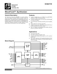
Cal Period<br />
(4096 x L/R clocks)<br />
(85.33 ms @ 48kHz)<br />
DPD<br />
Filter Delay Time<br />
(~40 L/R periods)<br />
(~2 ms @ 48 kHz)<br />
Normal Operation<br />
DCAL<br />
Figure 6. Initial Calibration Cycle Timing<br />
3-48 DS23F1