Download the Software PDF - Bosch Rexroth Corp.
Download the Software PDF - Bosch Rexroth Corp.
Download the Software PDF - Bosch Rexroth Corp.

Create successful ePaper yourself
Turn your PDF publications into a flip-book with our unique Google optimized e-Paper software.
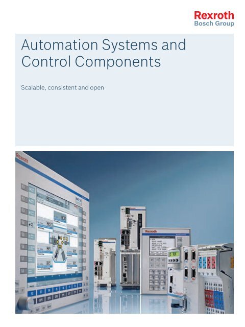
Automation Systems and<br />
Control Components<br />
Scalable, consistent and open
Automation Systems and<br />
Control Components<br />
Scalable, consistent and open
Automation expertise | Automation systems and control components<br />
3<br />
Contents<br />
Expertise in automation technology 04<br />
Automation systems – summary 08<br />
IndraMotion MTX – CNC system for machine<br />
tools<br />
10<br />
Discover <strong>the</strong> unlimited possibilities of <strong>Rexroth</strong>’s automation<br />
systems. They integrate all control and drive components to<br />
provide optimum automation solutions: state-of-<strong>the</strong>-art,<br />
ultra-efficient, and highly future-proof.<br />
IndraMotion MLD – drive-based motion logic<br />
system<br />
IndraMotion MLC – controller-based motion<br />
logic system<br />
22<br />
30<br />
IndraLogic – open PLC systems 42<br />
Control components – summary 58<br />
IndraWorks – engineering framework 60<br />
IndraControl V – human-machine interfaces<br />
(HMI) and industrial PCs<br />
80<br />
IndraControl L – controller-based hardware 122<br />
Inline – I/O technology in IP20 140<br />
IndraControl S20 – I/O technology in IP20 176<br />
IndraControl S67 – I/O technology in IP67 188<br />
Fieldline – I/O technology in IP67 202<br />
Interconnection technology – cables and plugs 208<br />
Glossary 220<br />
Standards and certificates 223<br />
<br />
<strong>Bosch</strong> <strong>Rexroth</strong> AG, 72 604 EN/2012-04
4 Automation systems and control components | Automation expertise<br />
Expertise in automation technology<br />
Discover <strong>the</strong> unlimited possibilities of <strong>Rexroth</strong>’s automation<br />
systems. They integrate all control and drive components to<br />
provide optimum automation solutions: state-of-<strong>the</strong>-art,<br />
ultra-efficient, and highly future-proof.<br />
Based on decades of experience, we developed a state of<br />
<strong>the</strong> art control platform allowing you, as a machine<br />
manufacturer, to realize your innovative machine concepts.<br />
The extensive control portfolio opens up completely new<br />
perspectives for easy, safe, and economic automation and<br />
flexible extension of your system.<br />
We are sure you will find your preferred control solution<br />
with <strong>Rexroth</strong>. On <strong>the</strong> one hand, we offer complete<br />
automation systems and our modern controls cover all<br />
automation tasks – from a compact PLC to a flexible<br />
motion control and innovative CNC control. On <strong>the</strong> o<strong>the</strong>r<br />
hand, <strong>the</strong> performance and function of <strong>the</strong> drive, controller,<br />
or PC-based control systems can be adapted exactly to<br />
your individual requirements.<br />
Design your future with <strong>the</strong> flexibility you need and<br />
configure <strong>the</strong> control solutions exactly how you require<br />
<strong>the</strong>m for your applications – with systems, modules, and<br />
components from <strong>Rexroth</strong>.<br />
<strong>Bosch</strong> <strong>Rexroth</strong> AG, 72 604 EN/2012-04
Automation expertise | Automation systems and control components<br />
5<br />
Uniform engineering software for all solutions<br />
IndraWorks now allows you to solve all of your tasks with<br />
one single software – from project planning and<br />
programming to visualization and diagnostics. Its innovative<br />
feature: IndraWorks is universally available in all of our<br />
automation systems as an integrated engineering software<br />
– you’ll profit from <strong>the</strong> fast access to all functions and data<br />
of <strong>the</strong> control components and from <strong>the</strong> increased<br />
understandability of your automation solution.<br />
Consistent PLC logic according to IEC 61131-3<br />
Using <strong>the</strong> IndraLogic PLC runtime system in all of your<br />
automation solutions, you will be able to standardize your<br />
application programs in conformance with IEC 61131-3.<br />
With its user-friendly handling, this program system that is<br />
fully integrated in IndraWorks facilitates <strong>the</strong> creation of<br />
modularized and object-oriented applications.<br />
functions which you can easily integrate in your<br />
applications by simple parameterization.<br />
sercos – E<strong>the</strong>rnet-based communication<br />
The 3rd generation sercos meets all requirements for a<br />
future-oriented machine network – open, consistent and<br />
fast. From drives and controls to I/O peripherals, all<br />
automation components are easily combined to form an<br />
understandable and capable overall system. With real-time<br />
and innovative features, sercos <strong>the</strong> automation bus<br />
provides maximum performance and flexibility in all<br />
applications.<br />
Maximum flexibility with integrated motion logic<br />
The family of open system software combines all<br />
components from <strong>Rexroth</strong> to provide integrated solutions<br />
with motion and logic control. Using IndraMotion, you can<br />
implement all of your centralized and distributed control<br />
designs, customized to your industry-specific requirements.<br />
Scalable platforms for all control topologies<br />
The scalable control, visualization and I/O hardware<br />
platforms allow easy, flexible and integrated automation of<br />
your applications. Combined with open communication<br />
interfaces, <strong>the</strong>se hardware platforms provide automation<br />
solutions that are also sustainable in <strong>the</strong> future and allow<br />
factory automation with any degree of freedom.<br />
Safety on board – certified integrated safety solution<br />
The drive integrated safety technology „Safety on Board“<br />
provides reliable personnel protection for all motion<br />
applications. With <strong>the</strong> IndraDrive family, <strong>the</strong> “Safety on<br />
Board” system, certified according to EN ISO 13849-1, Cat.<br />
3 PL d and EN 62061 SIL 2, provides comprehensive safety<br />
<br />
<strong>Bosch</strong> <strong>Rexroth</strong> AG, 72 604 EN/2012-04
Bildname<br />
S2373_01G.fh11<br />
Ersetzt durch<br />
Bilddatenbank<br />
qja qnein<br />
Nr.:<br />
Produktkatalog<br />
qja qnein<br />
Nr.:<br />
Bild-/Grafikart<br />
CD-ROM<br />
Auftraggeber<br />
BRC/MKT1<br />
Aufnahmedatum/-ort 01.2005<br />
Auftragnehmer<br />
Techno-Artworks<br />
Verwendungsnachweis<br />
Bildname<br />
S2447_01G.fh11<br />
Ersetzt durch<br />
Bilddatenbank<br />
qja qnein<br />
Nr.:<br />
Produktkatalog<br />
qja qnein<br />
Nr.:<br />
Bild-/Grafikart<br />
Weltkugel<br />
Auftraggeber<br />
BRC/MKT1<br />
Aufnahmedatum/-ort 01.2005<br />
Auftragnehmer<br />
Techno-Artworks<br />
Verwendungsnachweis<br />
Bildname<br />
S2373_01G.fh11<br />
Ersetzt durch<br />
Bilddatenbank<br />
qja qnein<br />
Nr.:<br />
Produktkatalog<br />
qja qnein<br />
Nr.:<br />
Bild-/Grafikart<br />
CD-ROM<br />
Auftraggeber<br />
BRC/MKT1<br />
Aufnahmedatum/-ort 01.2005<br />
Auftragnehmer<br />
Techno-Artworks<br />
Verwendungsnachweis<br />
Bildname<br />
S2478_02G.fh11<br />
Ersetzt durch<br />
Bilddatenbank<br />
qja qnein<br />
Nr.:<br />
Produktkatalog<br />
qja qnein<br />
Nr.:<br />
Bild-/Grafikart<br />
Auftraggeber<br />
BRC/MKT1<br />
Aufnahmedatum/-ort 01.2005<br />
Auftragnehmer<br />
Techno-Artworks<br />
Verwendungsnachweis<br />
6 Automation systems and control components | Automation expertise<br />
Automation system and<br />
control components at a glance<br />
Bildname<br />
S2478_01G.fh11<br />
Ersetzt durch<br />
Bilddatenbank<br />
qja qnein<br />
Nr.:<br />
Produktkatalog<br />
qja qnein<br />
Nr.:<br />
IndraMotion MLD<br />
Bild-/Grafikart<br />
Auftraggeber<br />
BRC/MKT1<br />
Aufnahmedatum/-ort 01.2005<br />
Auftragnehmer<br />
Techno-Artworks<br />
Verwendungsnachweis<br />
Drive-based<br />
motion logic system<br />
IndraMotion MLC<br />
Controller-based<br />
motion logic system<br />
E<strong>the</strong>rnet<br />
IndraControl V<br />
VPP<br />
VPB<br />
VDP<br />
Industrial PC<br />
IndraControl L<br />
L10<br />
L20<br />
L25<br />
Controller-based control hardware<br />
L40<br />
Inline/<br />
IndraControl S20/S67<br />
Fieldline<br />
Inline<br />
bus coupler<br />
Inline<br />
block I/O,<br />
digital<br />
Inline<br />
block I/O,<br />
analog<br />
Inline<br />
I/O modules<br />
I<br />
IndraDrive<br />
IndraDrive C<br />
IndraDrive M<br />
IndraDrive Cs<br />
Drives<br />
<strong>Bosch</strong> <strong>Rexroth</strong> AG, 72 604 EN/2012-04
Bildname<br />
S2373_01G.fh11<br />
Ersetzt durch<br />
Bilddatenbank<br />
qja qnein<br />
Nr.:<br />
Produktkatalog<br />
qja qnein<br />
Nr.:<br />
Bild-/Grafikart<br />
CD-ROM<br />
Auftraggeber<br />
BRC/MKT1<br />
Aufnahmedatum/-ort 01.2005<br />
Auftragnehmer<br />
Techno-Artworks<br />
Verwendungsnachweis<br />
Bildname<br />
S2478_02G.fh11<br />
Ersetzt durch<br />
Bilddatenbank<br />
qja qnein<br />
Nr.:<br />
Produktkatalog<br />
qja qnein<br />
Nr.:<br />
Bild-/Grafikart<br />
Auftraggeber<br />
BRC/MKT1<br />
Aufnahmedatum/-ort 01.2005<br />
Auftragnehmer<br />
Techno-Artworks<br />
Verwendungsnachweis<br />
Bildname<br />
S2373_01G.fh11<br />
Ersetzt durch<br />
Bilddatenbank<br />
qja qnein<br />
Nr.:<br />
Produktkatalog<br />
qja qnein<br />
Nr.:<br />
Bild-/Grafikart<br />
CD-ROM<br />
Auftraggeber<br />
BRC/MKT1<br />
Aufnahmedatum/-ort 01.2005<br />
Auftragnehmer<br />
Techno-Artworks<br />
Verwendungsnachweis<br />
Automation expertise | Automation systems and control components 7<br />
IndraMotion MTX<br />
CNC systems<br />
IndraLogic<br />
PLC<br />
IndraWorks<br />
Engineering + operation<br />
Bildname<br />
Ersetzt durch<br />
Bilddatenbank<br />
Produktkatalog<br />
S<br />
q<br />
N<br />
q<br />
N<br />
Bild-/Grafikart<br />
L<br />
Auftraggeber<br />
B<br />
Aufnahmedatum/-ort 0<br />
Auftragnehmer<br />
T<br />
Verwendungsnachweis<br />
Engineering<br />
VDP40<br />
VAM VAK VEP<br />
VEP30<br />
VCP VCH<br />
Control panels/keyboards Embedded PC Controller<br />
L45<br />
L65/85<br />
Function modules<br />
Controller-based control hardware<br />
IndraControl S20<br />
bus coupler<br />
IndraControl S20<br />
I/O modules<br />
IndraControl S67<br />
bus coupler<br />
IndraControl S67<br />
I/O modules<br />
Fieldline M8<br />
I/O modules<br />
IndraDrive Mi<br />
Drives<br />
IndraDyn<br />
Motors<br />
<strong>Bosch</strong> <strong>Rexroth</strong> AG, 72 604 EN/2012-04
8 Automation systems and control components | Automation systems<br />
Automation systems –<br />
CNC, PLC, and motion control<br />
<strong>Bosch</strong> <strong>Rexroth</strong> AG, 72 604 EN/2012-04
Automation systems | Automation systems and control components<br />
9<br />
IndraMotion MTX –<br />
CNC system for machine tools 10<br />
IndraMotion MLD –<br />
drive-based motion logic system 22<br />
IndraMotion MLC –<br />
controller-based motion logic system 30<br />
IndraLogic –<br />
open PLC systems 42<br />
<br />
<strong>Bosch</strong> <strong>Rexroth</strong> AG, 72 604 EN/2012-04
10 Automation systems and control components | IndraMotion MTX<br />
IndraMotion MTX –<br />
highly productive CNC solution<br />
for all machine tools<br />
<strong>Rexroth</strong> IndraMotion MTX is <strong>the</strong> individually scalable<br />
CNC platform with integrated PLC for successful<br />
machining and forming applications. Excellent<br />
performance and comprehensive technology functions<br />
open new horizons for maximum productivity and<br />
flexibility.<br />
Whe<strong>the</strong>r you control a standard machine or a fully<br />
automated production system – IndraMotion MTX always<br />
ensures highly dynamic processing with minimized<br />
downtimes in your application. The following system<br />
versions are available:<br />
▶▶<br />
▶▶<br />
▶▶<br />
▶▶<br />
IndraMotion MTX micro – <strong>the</strong> tailor-made, compact<br />
system solution for turning and milling machines<br />
IndraMotion MTX standard – <strong>the</strong> modular CNC control<br />
for universal machines and machining centers<br />
IndraMotion MTX performance – <strong>the</strong> high-performance<br />
CNC control for fast machining centers with up to<br />
64 axes<br />
IndraMotion MTX advanced – <strong>the</strong> CNC control with extra<br />
power for multi-technology machining with <strong>the</strong> highest<br />
dynamics<br />
Your benefits<br />
▶▶<br />
Innovative CNC kernel with comprehensive technology<br />
functions for turning, milling, drilling, grinding, bending,<br />
nibbling, punching, shape cutting and handling<br />
▶▶<br />
Shortest CNC cycle times, even for high-speed<br />
machining<br />
▶▶<br />
Minimum PLC processing times<br />
▶▶<br />
Open system platform<br />
▶▶<br />
Performance and function individually scalable<br />
▶▶<br />
sercos III automation bus for fast, continuous<br />
communication between control, drives, and<br />
I/O components<br />
▶▶<br />
Uniform operating concept for easy programming<br />
▶▶<br />
Flexibly configurable user interface<br />
▶▶<br />
Open standards for easy connection of higher-order<br />
ERP systems<br />
IndraMotion MTX is <strong>the</strong> tailor-made CNC solution for<br />
turning, milling, drilling, grinding, bending, nibbling,<br />
punching, and shape cutting.<br />
<strong>Bosch</strong> <strong>Rexroth</strong> AG, 72 604 EN/2012-04
IndraMotion MTX | Automation systems and control components<br />
11<br />
Open, complete, and efficient<br />
▶▶<br />
▶▶<br />
▶▶<br />
Highest manufacturing precision down to <strong>the</strong><br />
nanometer range<br />
Modern CNC solution for excellent performance<br />
Shortest CNC and PLC cycle times for dynamic<br />
machining<br />
Application examples:<br />
IndraMotion MTX micro is <strong>the</strong> compact, powerful, and CNC<br />
cost-effective solution from <strong>Rexroth</strong> for standard turning<br />
and milling machines.<br />
▶▶<br />
Turning with constant cutting speed<br />
▶▶<br />
Rigid or non-rigid tapping<br />
▶▶<br />
Combined spindle/revolver axes<br />
▶▶<br />
Milling with 2.5D and 3D machining with up to<br />
4 interpolating axes<br />
▶▶<br />
Direct programming of drawing dimensions<br />
▶▶<br />
Turning, drilling, and milling cycles for complete<br />
machining<br />
▶▶<br />
Cylinder surface and C-axis machining<br />
The modular IndraMotion MTX system controls standard<br />
and universal machines for milling, turning, drilling,<br />
grinding, nibbling, punching, shape cutting, and bending<br />
easily, quickly, and effectively. Proven CNC functions cover a<br />
broad range of applications from highly precise and quick<br />
machining of free-form surfaces to <strong>the</strong> most-demanding<br />
grinding applications, as well as plasma, laser, or waterjet<br />
machines.<br />
▶▶<br />
Spline interpolation and B-spline compressor<br />
▶▶<br />
Nano interpolation<br />
▶▶<br />
5-axis machining and 3D cutter radius compensation<br />
▶▶<br />
Any combination of machining technologies in one<br />
process, e.g. for turning on milling machines<br />
▶▶<br />
Spindle coupling and electronic transmission<br />
▶▶<br />
High-speed I/O in interpolator cycle<br />
▶▶<br />
Intelligent, hydraulic axis control and interpolation<br />
between hydraulic and electric axes<br />
▶▶<br />
SafeMotion for integrated safety functions<br />
<br />
<strong>Bosch</strong> <strong>Rexroth</strong> AG, 72 604 EN/2012-04
12 Automation systems and control components | IndraMotion MTX<br />
IndraMotion MTX –<br />
technical data<br />
MTX micro MTX standard MTX performance MTX advanced<br />
Machining technologies<br />
Turning ● ● ● ●<br />
Milling ● ● ● ●<br />
Drilling ● ● ● ●<br />
Grinding ● ● ● ●<br />
Nibbling, shape cutting ● ● ● ●<br />
Forming – ● ● ●<br />
Axis control<br />
Default number of axes 3/4 ● 8 ● 8 ● 8 ●<br />
Max. number of axes 6 ○ 8 ● 64 ○ 64 ○<br />
Max. number of spindles <strong>the</strong>reof 2 ● 2 ● 32 ○ 32 ○<br />
Default number of independent channels 2 ● 2 ● 3 ● 3 ●<br />
Max. number of independent channels 2 ● 2 ● 12 ○ 12 ○<br />
Default number of interpolating axes per channel 4 ● 4 ● 4 ● 4 ●<br />
Max. number of interpolating axes per channel 4 ● 4 ● 8* ○ 8* ○<br />
Linear axes ● ● ● ●<br />
Rotary axes ● ● ● ●<br />
Endlessly turning rotary axis ● ● ● ●<br />
Hirth axes ● ● ● ●<br />
Spindle/C-axis switching ● ● ● ●<br />
Max. number of gantry groups per channel 1 4 ○ 2) 6) 8 ○ 2) 3) 6) 8 ○ 2) 3) 6)<br />
Channel-crossing axis transfer ● ● ● ●<br />
Electronic cam ● ● ● ●<br />
Spindle coupling via electronic transmission ● ○ 7) ○ 7) ○ 7)<br />
<strong>Software</strong> limits ● ● ● ●<br />
Main spindle synchronization ● ○ 1) 2) ○ 2) 2) 3) ○ 2) 2) 3)<br />
Axis-specific jerk limitation ● ● ● ●<br />
Integrated safety system according to EN ISO 13849-1<br />
and EN 62061 (safe stop, safe motion)<br />
– <br />
Interpolation functions<br />
Linear interpolation ● ● ● ●<br />
Linear interpolation with/without exact stop ● ● ● ●<br />
Circular interpolation with radius and center-point<br />
programming, helical interpolation<br />
● ● ● ●<br />
Circular interpolation with tangential entry ● ● ● ●<br />
Rigid tapping cycle ● ○ 1) 6) ○ 1) 6) ○ 1) 6)<br />
Thread cutting ● ○ 1) ○ 1) ○ 1)<br />
Cylinder surface transformation ● ● ● ●<br />
● Default ○ Optional Optional in connection with a PC Optional with IndraDrive<br />
1) “Turning 1” technology package 2) “Milling 1” technology package 3) “Milling 2” technology package 4) “Turning” CNC simulation<br />
5) “Milling” CNC simulation 6) “Shape cutting” technology package 7) “Electronic transmission” technology package<br />
*) An export license is required for this option. Per part I C of <strong>the</strong> export list (EC Regulation) item 2D002.<br />
<strong>Bosch</strong> <strong>Rexroth</strong> AG, 72 604 EN/2012-04
IndraMotion MTX | Automation systems and control components<br />
13<br />
MTX micro MTX standard MTX performance MTX advanced<br />
Machining technologies<br />
C-axis transformation ● ● ● ●<br />
NC block preview, look-ahead<br />
Max. 1,000 blocks<br />
●<br />
Max. 1,000 blocks<br />
●<br />
Max. 1,000 blocks<br />
●<br />
Max. 1,000 blocks<br />
●<br />
5-axis transformation with TCP programming – – ○ 3) ○ 3)<br />
Jogging with active transformation – – ○ 3) ○ 3)<br />
Spline interpolation, C1 + C2, continuous cubic splines,<br />
B-splines, NURBS<br />
● ○ 1) 2) ○ 1) 2) 3) ○ 1) 2) 3)<br />
Nanometer resolution ● ● ● ●<br />
Feed functions<br />
Feed in mm/min or inch/min ● ● ● ●<br />
Time programming ● ● ● ●<br />
Feed rate per revolution ● ● ● ●<br />
Constant cutting speed ● ○ 1) ○ 1) ○ 1)<br />
Fixed Stop ● ● ● ●<br />
Torque reduction ● ● ● ●<br />
Shifts and compensations<br />
Mirroring, scaling, rotating ● ● ● ●<br />
Zero offsets ● ● ● ●<br />
Compensations and zero offsets<br />
programmable through CPL<br />
● ● ● ●<br />
Placements (FRAMES) ● ○ 2) ○ 2) 3) ○ 2) 3)<br />
2D compensation ● ● ● ●<br />
3D cutter radius compensation – – ○ 3) ○ 3)<br />
Compensation with plane switching ● ● ● ●<br />
Tangential tool guidance ● ● ● ●<br />
Tool management<br />
Integrated flexible tool management ● ● ● ●<br />
Configurable tool database ● ● ● ●<br />
Freely definable tool compensation<br />
(length, radius, cutting position compensation, user data)<br />
● ● ● ●<br />
Additive tool compensations (D compensations) – ● ● ●<br />
Access to tool data from PLC ● ● ● ●<br />
Access to tool data from CNC ● ● ● ●<br />
CNC programming<br />
Part program development DIN ISO 66025/<br />
RS 274D<br />
DIN ISO 66025/<br />
RS 274D<br />
DIN ISO 66025/<br />
RS 274D<br />
DIN ISO 66025/<br />
RS 274D<br />
High-level language programming, CPL<br />
(customer programming language)<br />
● ● ● ●<br />
Graphical NC simulation – ○ 4) 5) ○ 4) 5) ○ 4) 5)<br />
CNC user memory 64 MB 256 MB 512 MB 1,024 MB<br />
● Default ○ Optional Optional in connection with a PC Optional with IndraDrive<br />
1) “Turning 1” technology package 2) “Milling 1” technology package 3) “Milling 2” technology package 4) “Turning” CNC simulation<br />
5) “Milling” CNC simulation 6) “Shape cutting” technology package 7) “Electronic transmission” technology package<br />
*) An export license is required for this option. Per part I C of <strong>the</strong> export list (EC Regulation) item 2D002.<br />
<br />
<strong>Bosch</strong> <strong>Rexroth</strong> AG, 72 604 EN/2012-04
14 Automation systems and control components | IndraMotion MTX<br />
IndraMotion MTX –<br />
technical data<br />
MTX micro MTX standard MTX performance MTX advanced<br />
CNC programming<br />
Static memory 4 MB 8 MB 8 MB 16 MB<br />
Max. size of parts program<br />
8 MB<br />
PC hard disk<br />
(network file<br />
system) ●<br />
PC hard disk<br />
(network file<br />
system) ●<br />
PC hard disk<br />
(network file<br />
system) ●<br />
CompactFlash data memory ● ● ● ●<br />
Technology cycles<br />
Drilling ● ● ● ●<br />
Turning ● ● ● ●<br />
Milling ● ● ● ●<br />
Functions<br />
Dwell time in seconds ● ● ● ●<br />
Acceleration programming, loop gain programming ● ● ● ●<br />
Homing through NC program ● ● ● ●<br />
Absolute dimension, relative dimension ● ● ● ●<br />
Switching between inch and mm ● ● ● ●<br />
Probe, static/on-<strong>the</strong>-fly measurement ● ● ● ●<br />
Read process and drive data through sercos ● ● ● ●<br />
Roundings and chamfers ● ● ● ●<br />
Corner rounding with splines ● ● ● ●<br />
Laser power control ● ● ● ●<br />
Digitizing ● ● ● ●<br />
NC block defined by PLC ● ● ● ●<br />
Support for control elements<br />
Configurable operator screens – <br />
Cycle header/input support, OEM cycles – <br />
NC program restart/block search ● ● ● ●<br />
Dry run ● ● ● ●<br />
Retracting from and returning to <strong>the</strong> contour ● ● ● ●<br />
Retrace function: reversing over <strong>the</strong> contour ● ○ 6) ○ 6) ○ 6)<br />
PLC programming<br />
Integrated PLC: IndraLogic ● ● ● ●<br />
Programming languages according to IEC 61131-3<br />
(IL, LD, CFC, ST, SFC, FBD)<br />
● ● ● ●<br />
PLC program memory 2 MB 8 MB 8 MB 16 MB<br />
Number of local/on-board I/Os 32 I/16 O ● 8 I/8 O ● 8 I/8 O ● 8 I/8 O ●<br />
Max. number of local/on-board I/Os 96 I/48 O ○ ○ ○ ○<br />
Number of high-speed inputs/outputs 8 I/8 O ● 8 I/8 O ● 8 I/8 O ● 8 I/8 O ●<br />
Number of fieldbus inputs/outputs in bytes 8,192 I/8,192 O 8,192 I/8,192 O 8,192 I/8,192 O 8,192 I/8,192 O<br />
Multitasking ● ● ● ●<br />
Max. number of PLC tasks 2 16 16 16<br />
● Default ○ Optional Optional in connection with a PC Optional with IndraDrive<br />
(1) “Turning 1” technology package (2) “Milling 1” technology package (3) “Milling 2” technology package (4) “Turning” CNC simulation<br />
(5) “Milling” CNC simulation (6) “Shape cutting” technology package (7) “Electronic transmission” technology package<br />
*) An export license is required for this option. Per part I C of <strong>the</strong> export list (EC Regulation) item 2D002.<br />
<strong>Bosch</strong> <strong>Rexroth</strong> AG, 72 604 EN/2012-04
IndraMotion MTX | Automation systems and control components<br />
15<br />
MTX micro MTX standard MTX performance MTX advanced<br />
Diagnostic and startup tools<br />
Integrated, system-crossing engineering framework IndraWorks ○ ● ● ●<br />
Instructions and error messages in plain text ● ● ● ●<br />
Integrated drive project planning ● ● ● ●<br />
Drive oscilloscope ○ ● ● ●<br />
Integrated PLC project planning ○ ● ● ●<br />
Logic analyzer ○ ● ● ●<br />
Circular shape test ○ ● ● ●<br />
NC analyzer – ● ● ●<br />
Action recorder IndraMotion MTX acr – ○ ○ ○<br />
Cycle time analyzer IndraMotion MTX cta ○ ○ ○ ○<br />
Energy analyzer IndraMotion MTX ega ○ ○ ○ ○<br />
Remote condition monitoring system IndraMotion MTX rcm – ○ ○ ○<br />
Remote diagnosis I-Remote – ○ ○ ○<br />
IndraMotion MTX micro Trainer ● – – –<br />
IndraWorks view 3D – ○ ○ ○<br />
IndraWorks machine simulator – ○ ○ ○<br />
Open architecture<br />
Configurable user interface with all standard functions – ● ● ●<br />
User-specific operator screens – ● ● ●<br />
Adaptation and integration through standardized interfaces<br />
(OPC-UA, XML, ActiveX, .NET)<br />
– ● ● ●<br />
Control hardware and interfaces<br />
CPU IndraControl L45 IndraControl L65 IndraControl L85<br />
Digital drive interface sercos<br />
100 Mbaud<br />
●<br />
100 Mbaud ● 100 Mbaud ● 100 Mbaud ●<br />
PROFIBUS master/slave – 12 Mbaud ● 12 Mbaud ● 12 Mbaud ●<br />
E<strong>the</strong>rnet TCP/IP<br />
100 Mbaud<br />
●<br />
10/100 Mbaud ● 10/100 Mbaud ● 10/100 Mbaud ●<br />
E<strong>the</strong>rNet/IP adapter (slave) – ○ ○ ○<br />
PROFINET – ○ ○ ○<br />
<strong>Software</strong> and hardware<br />
Operating system Windows XP/Windows 7 – ○ ○ ○<br />
Panel PC IndraControl VPP 16/40*<br />
– CPU: Intel Celeron P4500, 1.86 GHz or Core I5, 2.4 GHz or Core I7, 2.66 GHz<br />
– TFT display: 30.5 cm (12")/38.1 cm (15")<br />
– ○ ○ ○<br />
– 16 machine control keys<br />
Industrial PC IndraControl VPB 40*<br />
– CPU: Intel Celeron P4500, 1.86 GHz or Core I5, 2.4 GHz or Core I7, 2.66 GHz<br />
– ○ ○ ○<br />
Embedded PC IndraControl VEP 40/50*<br />
– CPU: Intel Atom, 1.1 GHz, 1 GB RAM<br />
– TFT display: 30.5 cm (12")/38.1 cm (15")<br />
– ○ ○ ○<br />
– 16 machine control keys<br />
● Default ○ Optional Optional in connection with a PC Optional with IndraDrive<br />
(1) “Turning 1” technology package (2) “Milling 1” technology package (3) “Milling 2” technology package (4) “Turning” CNC simulation<br />
(5) “Milling” CNC simulation (6) “Shape cutting” technology package (7) “Electronic transmission” technology package<br />
*) An export license is required for this option. Per part I C of <strong>the</strong> export list (EC Regulation) item 2D002.<br />
<br />
<strong>Bosch</strong> <strong>Rexroth</strong> AG, 72 604 EN/2012-04
16 Automation systems and control components | IndraMotion MTX<br />
IndraMotion MTX micro –<br />
system configuration<br />
Example configuration<br />
Engineering<br />
E<strong>the</strong>rnet<br />
IndryDyn<br />
IndraControl V<br />
Inlne<br />
IndraDrive<br />
IndraDyn<br />
System configuration<br />
<strong>Software</strong><br />
Page(s)<br />
Engineering framework IndraWorks 60–79<br />
Drive control unit with integrated CNC<br />
Basic device IndraDrive HCT, IndraDrive HCQ See <strong>the</strong> IndraMotion MTX micro brochure<br />
Option modules Digital I/O 140–175<br />
Standard interfaces sercos, E<strong>the</strong>rnet TCP/IP –<br />
HMI technology<br />
Visualization device and operator panel IndraControl VDP80 See "IndraMotion MTX micro" brochure<br />
Drives and motors<br />
Drive system for additional axes IndraDrive See "Drive System <strong>Rexroth</strong> IndraDrive"<br />
Servo and main spindle motors IndraDyn See "Drive System <strong>Rexroth</strong> IndraDrive"<br />
<strong>Bosch</strong> <strong>Rexroth</strong> AG, 72 604 EN/2012-04
IndraMotion MTX | Automation systems and control components<br />
17<br />
IndraMotion MTX micro –<br />
ordering data<br />
Ordering data for firmware<br />
Description<br />
Firmware for IndraMotion MTX micro<br />
Ordering data for software and software options<br />
Description<br />
<strong>Software</strong> DVD, Engineering framework IndraWorks<br />
Single license, IndraWorks (Engineering MTX micro)<br />
Multiple license (25), ndraWorks (Eengineering MTX micro)<br />
<strong>Software</strong> DVD, MTX micro trainer<br />
Ordering data for hardware<br />
Description<br />
Basic device 4-axes, 32 I, 16 O<br />
Basic device 4-axes, 64 I, 32 O<br />
Basic device 4-axes, 96 I, 48 O<br />
Basic device 3-axes, 32 I, 16 O<br />
Basic device 3-axes, 64 I, 32 O<br />
Basic device 3-axes, 96 I, 48 O<br />
Turning control panel<br />
Milling control panel<br />
Turning control panel, graphite gray<br />
Milling control panel, graphite gray<br />
Universal control panel, graphite gray<br />
Basic device control panel connecting cable<br />
Type code<br />
FWA-MICRO*-MTX-xxVRS-NN<br />
Type code<br />
SWA-IWORKS-MTX-xxVRS-D0-DVD<br />
SWL-IWORKS-MTX-xxVRS-D0-MICRO<br />
SWL-IWORKS-MTX-xxVRS-D0-MICRO*M25<br />
SWA-MICRO*-MTX-xxVRS-A3-DVD**-TRAINER<br />
Type code<br />
HCQ02.1E-W0025-A-03-B-L8-1S-NN-NN-NN-FW<br />
HCQ02.1E-W0025-A-03-B-L8-1S-D1-NN-NN-FW<br />
HCQ02.1E-W0025-A-03-B-L8-1S-D1-D1-NN-FW<br />
HCT02.1E-W0025-A-03-B-L8-2S-NN-NN-NN-FW<br />
HCT02.1E-W0025-A-03-B-L8-2S-D1-NN-NN-FW<br />
HCT02.1E-W0025-A-03-B-L8-2S-D1-D1-NN-FW<br />
VDP80.1FAN-C1-NN-EN<br />
VDP80.1FBN-C1-NN-EN<br />
VDP80.1FGN-C1-NN-EN<br />
VDP80.1FHN-C1-NN-EN<br />
VDP80.1FKN-C1-NN-EN<br />
RKB0030<br />
xx = software/firmware version<br />
Current documentation can be found in <strong>the</strong> Internet at www.boschrexroth.com/mediadirectory.<br />
<br />
<strong>Bosch</strong> <strong>Rexroth</strong> AG, 72 604 EN/2012-04
VAC 30<br />
18 Automation systems and control components | IndraMotion MTX<br />
IndraMotion MTX standard –<br />
system configuration<br />
Example configuration<br />
Engineering<br />
E<strong>the</strong>rnet<br />
IndraControl L<br />
IndraControl V<br />
Inline<br />
IndraDrive<br />
Hydraulics<br />
IndraDyn<br />
System configuration<br />
<strong>Software</strong><br />
Page(s)<br />
Engineering framework IndraWorks 60 – 79<br />
Control components<br />
Control hardware IndraControl L45 122 – 138<br />
Standard interfaces sercos, PROFIBUS, E<strong>the</strong>rnet TCP/IP, E<strong>the</strong>rNet/IP –<br />
HMI/PC technology<br />
Visualization devices, controller-based IndraControl VCP, VCH 84 – 91<br />
Visualization devices, embedded PC IndraControl VEP 92 – 97<br />
Visualization devices, industrial PC IndraControl VPP, IndraControl VPB, VDP 100 – 114<br />
I/O modules<br />
Distributed input/output modules in IP20 Inline 140 – 175<br />
Distributed input/output modules in IP67 IndraControl S67 188 – 201<br />
Drives and motors<br />
Drive system IndraDrive and IndraDyn See "Drive System<br />
<strong>Rexroth</strong> IndraDrive"<br />
<strong>Bosch</strong> <strong>Rexroth</strong> AG, 72 604 EN/2012-04
IndraMotion MTX | Automation systems and control components<br />
19<br />
IndraMotion MTX standard –<br />
ordering data<br />
Ordering data for firmware<br />
Description<br />
Firmware for IndraMotion MTX standard<br />
Ordering data for software and software options<br />
Description<br />
<strong>Software</strong> DVD, Engineering framework IndraWorks<br />
Single license, IndraWorks (Operation)<br />
Multiple license (25), IndraWorks (Operation)<br />
Single license, IndraWorks (Operation and Engineering)<br />
Multiple license (25), IndraWorks (Operation and Engineering)<br />
Single license, IndraWorks (Offline Programming)<br />
Multiple license (25), IndraWorks (Offline Programming)<br />
Single license, IndraWorks (OPC server)<br />
Multiple license (25), IndraWorks (OPC server)<br />
Option, technology package – turning 1<br />
Option, technology package – milling 1 (DE/EN)<br />
Option, electronic gear and system axis coupling<br />
Option, action recorder<br />
Option, technology package – shape cutting<br />
Option, cycle time analyzer<br />
Option, cycle time analyzer (on dongle)<br />
Option, energy analyzer<br />
Option, energy analyzer (on dongle)<br />
Option, efficiency workbench recorder (for CTA and EGA)<br />
Option, remote condition monitoring runtime<br />
Option, NC simulation, milling<br />
Option, NC simulation, turning<br />
Ordering data for hardware<br />
Description<br />
IndraControl L45 with sercos, PROFIBUS<br />
Type code<br />
FWA-CML45*-MTX-xxVRS-NN<br />
Type code<br />
SWA-IWORKS-MTX-xxVRS-D0-DVD<br />
SWL-IWORKS-MTX-xxVRS-D0-OPD<br />
SWL-IWORKS-MTX-xxVRS-D0-OPD*M25<br />
SWL-IWORKS-MTX-xxVRS-D0-OPDENG<br />
SWL-IWORKS-MTX-xxVRS-D0-OPDENG*M25<br />
SWL-IWORKS-MTX-xxVRS-D0-WORKSTATION<br />
SWL-IWORKS-MTX-xxVRS-D0-WORKSTATION*M25<br />
SWL-IWORKS-MTX-xxVRS-D0-COM<br />
SWL-IWORKS-MTX-xxVRS-D0-COM*M25<br />
SWS-MTX***-RUN-NNVRS-D0-TUR1<br />
SWS-MTX***-RUN-NNVRS-D0-BAZ1<br />
SWS-MTX***-RUN-NNVRS-D0-GEAR<br />
SWS-MTX***-RUN-NNVRS-D0-ACR<br />
SWS-MTX***-RUN-NNVRS-D0-SHC1<br />
SWS-MTX***-RUN-NNVRS-D0-CTA*ANALYZER<br />
SWS-MTX***-RUN-NNVRS-D0-CTA*ANALYZER-DGL<br />
SWS-MTX***-RUN-NNVRS-D0-EGA*ANALYZER<br />
SWS-MTX***-RUN-NNVRS-D0-EGA*ANALYZER-DGL<br />
SWS-MTX***-RUN-NNVRS-D0-EWB*RECORDER<br />
SWS-MTX***-RUN-NNVRS-D0-RCM<br />
SWS-MTX***-RUN-NNVRS-D0-SIM*M<br />
SWS-MTX***-RUN-NNVRS-D0-SIM*T<br />
Type code<br />
CML45.1-3P-504-NA-NNNN-NW<br />
xx = software/firmware version<br />
Current documentation can be found in <strong>the</strong> Internet at www.boschrexroth.com/mediadirectory.<br />
<br />
<strong>Bosch</strong> <strong>Rexroth</strong> AG, 72 604 EN/2012-04
VAC 30<br />
VAC 30<br />
VAC 30<br />
VAC 30<br />
VAC 30<br />
20 Automation systems and control components | IndraMotion MTX<br />
IndraMotion MTX performance/advanced –<br />
system configuration<br />
Controller-based<br />
PC-based<br />
Engineering<br />
Example configuration<br />
E<strong>the</strong>rnet<br />
Engineering<br />
Engineering<br />
Engineering<br />
Example configuration<br />
Engineering<br />
E<strong>the</strong>rnet<br />
E<strong>the</strong>rnet<br />
IndraControl L<br />
IndraControl V<br />
E<strong>the</strong>rnet<br />
E<strong>the</strong>rnet<br />
Plug-in card<br />
IndraControl L IndraControl V<br />
IndraControl V<br />
Plug-in card<br />
IndraControl V<br />
IndraControl L<br />
IndraControl V<br />
Inline<br />
Inline<br />
Inline<br />
IndraDrive<br />
IndraDrive<br />
IndraDrive<br />
Hydraulics<br />
Inline<br />
Inline<br />
IndraDrive<br />
IndryDyn<br />
IndraDrive<br />
Hydraulics<br />
Hydraulics<br />
IndryDyn<br />
IndraDyn<br />
IndraDyn<br />
IndryDyn<br />
System configuration<br />
<strong>Software</strong><br />
Page(s)<br />
Engineering framework IndraWorks 60 – 79<br />
Control components<br />
Control hardware IndraControl L65, IndraControl L85 122 – 138<br />
Standard interfaces sercos, PROFIBUS, E<strong>the</strong>rnet TCP/IP, E<strong>the</strong>rNet/IP –<br />
HMI/PC technology<br />
Visualization devices, controller-based IndraControl VCP, VCH 84 – 91<br />
Visualization devices, embedded PC IndraControl VEP 92 – 97<br />
Visualization devices, industrial PC IndraControl VPP, VPB, VDP 100 – 114<br />
I/O modules<br />
Distributed input/output modules in IP20 Inline 140 – 175<br />
Distributed input/output modules in IP67 IndraControl S67 188 – 201<br />
Drives and motors<br />
Drive system IndraDrive and IndraDyn See "Drive System<br />
<strong>Rexroth</strong> IndraDrive"<br />
<strong>Bosch</strong> <strong>Rexroth</strong> AG, 72 604 EN/2012-04
IndraMotion MTX | Automation systems and control components<br />
21<br />
IndraMotion MTX performance/advanced –<br />
ordering data<br />
Ordering data for firmware<br />
Description<br />
Firmware for IndraMotion MTX performance<br />
Firmware for IndraMotion MTX advanced<br />
Ordering data for software and software options<br />
Description<br />
<strong>Software</strong> DVD, Engineering framework IndraWorks<br />
Single license, IndraWorks (Operation)<br />
Multiple license (25), IndraWorks (Operation)<br />
Single license, IndraWorks (Operation and Engineering)<br />
Multiple license (25), IndraWorks (Operation and Engineering)<br />
Single license, IndraWorks (Offline Programming)<br />
Multiple license (25), IndraWorks (Offline Programming)<br />
Single license, IndraWorks (OPC server)<br />
Multiple license (25), IndraWorks (OPC server)<br />
Option, technology package – turning 1<br />
Option, technology package – milling 1 (DE/EN)<br />
Option, technology package – milling 2 (DE/EN)<br />
Option, electronic gear and system axis coupling<br />
Option, action recorder<br />
Option, technology package – shape cutting<br />
Option, cycle time analyzer<br />
Option, cycle time analyzer (on dongle)<br />
Option, energy analyzer<br />
Option, energy analyzer (on dongle)<br />
Option, efficiency workbench recorder (for CTA and EGA)<br />
Option, remote condition monitoring runtime<br />
Option, NC simulation, milling<br />
Option, NC simulation, turning<br />
Ordering data for hardware<br />
Description<br />
Basic device IndraControl VP with plug-in card IndraControl P60<br />
Basic device IndraControl VP with plug-in card IndraControl P60 and<br />
high-speed I/O interface (8 I/8 O)<br />
Basic device IndraControl VP with plug-in card IndraControl P70<br />
Basic device IndraControl VP with plug-in card IndraControl P70 and<br />
high-speed I/O interface (8 I/8 O)<br />
IndraControl L65 with sercos, PROFIBUS<br />
IndraControl L85 with sercos, PROFIBUS<br />
Type code<br />
FWA-CMP60*-MTX-xxVRS-NN, FWA-CML65*-MTX-xxVRS-NN<br />
FWA-CMP70*-MTX-xxVRS-NN, FWA-CML85*-MTX-xxVRS-NN<br />
Type code<br />
SWA-IWORKS-MTX-xxVRS-D0-DVD<br />
SWL-IWORKS-MTX-xxVRS-D0-OPD<br />
SWL-IWORKS-MTX-xxVRS-D0-OPD*M25<br />
SWL-IWORKS-MTX-xxVRS-D0-OPDENG<br />
SWL-IWORKS-MTX-xxVRS-D0-OPDENG*M25<br />
SWL-IWORKS-MTX-xxVRS-D0-WORKSTATION<br />
SWL-IWORKS-MTX-xxVRS-D0-WORKSTATION*M25<br />
SWL-IWORKS-MTX-xxVRS-D0-COM<br />
SWL-IWORKS-MTX-xxVRS-D0-COM*M25<br />
SWS-MTX***-RUN-NNVRS-D0-TUR1<br />
SWS-MTX***-RUN-NNVRS-D0-BAZ1<br />
SWS-MTX***-RUN-NNVRS-D0-BAZ2<br />
SWS-MTX***-RUN-NNVRS-D0-GEAR<br />
SWS-MTX***-RUN-NNVRS-D0-ACR<br />
SWS-MTX***-RUN-NNVRS-D0-SHC1<br />
SWS-MTX***-RUN-NNVRS-D0-CTA*ANALYZER<br />
SWS-MTX***-RUN-NNVRS-D0-CTA*ANALYZER-DGL<br />
SWS-MTX***-RUN-NNVRS-D0-EGA*ANALYZER<br />
SWS-MTX***-RUN-NNVRS-D0-EGA*ANALYZER-DGL<br />
SWS-MTX***-RUN-NNVRS-D0-EWB*RECORDER<br />
SWS-MTX***-RUN-NNVRS-D0-RCM<br />
SWS-MTX***-RUN-NNVRS-D0-SIM*M<br />
SWS-MTX***-RUN-NNVRS-D0-SIM*T<br />
Type code<br />
CFG-VPN01A1-GC-NN-NN<br />
CFG-VPN01A1-GC-IC-NN<br />
CFG-VPN01A1-WC-NN-NN<br />
CFG-VPN01A1-WC-NO-NN<br />
CML65.1-3P-504-NA-NNNN-NW<br />
CML85.1-3P-504-NA-NNNN-NW<br />
xx = software/firmware version<br />
Current documentation can be found in <strong>the</strong> Internet at www.boschrexroth.com/mediadirectory.<br />
<br />
<strong>Bosch</strong> <strong>Rexroth</strong> AG, 72 604 EN/2012-04
22 Automation systems and control components | IndraMotion MLD<br />
IndraMotion MLD –<br />
drive-based automation solution for<br />
single-axis and multi-axis applications<br />
The integrated IndraMotion MLD automation solution is<br />
based on <strong>the</strong> scalable IndraDrive platform. Highperformance<br />
motion control and PLC functions are joined<br />
to form a complete automation system for modern<br />
machine concepts. Higher-level controls are no longer<br />
necessary. This provides a clear and fast solution for<br />
complex control and motion tasks.<br />
The drive-based solution is scalable as a single-axis control<br />
for simple applications as well as a multi-axis control for<br />
applications with a maximum of 10 axes. Ready-to-use<br />
function libraries simplify <strong>the</strong> use of intelligent drive<br />
functions of IndraDrive. In addition, function blocks<br />
according to PLCopen provide access to standardized<br />
motion control functions. The open technology and<br />
communication interfaces simplify integration of<br />
IndraMotion MLD in <strong>the</strong> automation design.<br />
Your benefits<br />
▶▶<br />
Compact system for modular distributed architectures<br />
▶▶<br />
Scalable as single-axis or multi-axis control<br />
▶▶<br />
Electronic synchronization of up to 10 servo-axes<br />
▶▶<br />
Ready-to-use function libraries according to PLCopen<br />
▶▶<br />
Integrated intelligent drive functions<br />
▶▶<br />
Optional interfaces for communication, safety and<br />
additional encoder<br />
▶▶<br />
Drive-integrated motion control and PLC according to<br />
IEC 61131-3<br />
▶▶<br />
Certified safety technology according to<br />
EN ISO 13849‐1, category 3 PL d and EN 62061 SIL 2<br />
▶▶<br />
Intuitive engineering framework IndraWorks for project<br />
development, programming, visualization and<br />
diagnostics<br />
▶▶<br />
<strong>Software</strong> options with technology packages and turnkey<br />
solutions<br />
IndraMotion MLD from <strong>Rexroth</strong> helps you to integrate your<br />
valuable know-how directly in <strong>the</strong> drive, thus ensuring your<br />
competitive edge.<br />
<strong>Bosch</strong> <strong>Rexroth</strong> AG, 72 604 EN/2012-04
IndraMotion MLD | Automation systems and control components<br />
<br />
23<br />
Compact, intelligent and economic<br />
▶▶<br />
▶▶<br />
▶▶<br />
Very cost-effective solution for single-axis and multiaxis<br />
applications without any additional hardware<br />
Minimized engineering through conformity with IEC and<br />
PLCopen<br />
Faster implementation of your system solution through<br />
predefined technology packages<br />
As a sub-system, IndraMotion MLD can be flexibly<br />
integrated in <strong>the</strong> most varied machines and systems and<br />
ensures <strong>the</strong> highest productivity and efficiency in many<br />
applications:<br />
▶▶<br />
Machine tools<br />
▶▶<br />
Production machines<br />
▶▶<br />
Process systems<br />
▶▶<br />
Heavy load handling<br />
▶▶<br />
Automotive<br />
▶▶<br />
Renewable energies<br />
▶▶<br />
Cellulose and paper<br />
▶▶<br />
Solar technology<br />
IndraMotion MLD controls drive-based compact systems,<br />
as well as modules in a complex system, that demand<br />
extremely precise and fast drive synchronization in <strong>the</strong><br />
following areas:<br />
▶▶<br />
Packaging technology<br />
▶▶<br />
Printing presses and processing machines<br />
▶▶<br />
Forming machines and simple machine tools<br />
▶▶<br />
Bending and drawing machines, spinning la<strong>the</strong>s<br />
▶▶<br />
Press automation<br />
▶▶<br />
Nibbling and punching<br />
▶▶<br />
Wood processing<br />
▶▶<br />
Assembly and handling<br />
▶▶<br />
Transfer and transport<br />
▶▶<br />
Warehouses and storage<br />
<br />
<strong>Bosch</strong> <strong>Rexroth</strong> AG, 72 604 EN/2012-04
24 Automation systems and control components | IndraMotion MLD<br />
IndraMotion MLD –<br />
technical data<br />
MLD-M<br />
IndraDrive<br />
Cs<br />
MLD-M<br />
IndraDrive<br />
C/M<br />
MLD-S<br />
IndraDrive<br />
Cs<br />
MLD-S<br />
IndraDrive<br />
C/M<br />
MLD-S<br />
IndraDrive<br />
Mi<br />
Control<br />
Runtime system Integrated motion logic systems ● ● ● ● ●<br />
Multitasking ● ● ● ● ●<br />
Data management Code, data, retentive data, user data ● ● ● ● ●<br />
Storage Boot project ● ● ● ● ●<br />
PLC project as packed archive file ● ● ● ● ●<br />
User data to <strong>the</strong> internal memory and<br />
a removable storage medium<br />
● ● ● ● ●<br />
Support System events ● ● ● ● ●<br />
Probe function, control ○ ○ ○ ○ ○<br />
User memory Total: code, data 4 MB 4 MB 512 kB 512 kB 512 kB<br />
Retentive memory Total: system, user 32 kB 32 kB 32 kB 32 kB 32 kB<br />
On-board diagnosis and settings<br />
Status display<br />
(boot, sercos, test)<br />
Display ● ● ● ● –<br />
Errors, warnings, messages,<br />
system reset<br />
Display, keys ● ● ● ● –<br />
E<strong>the</strong>rnet settings<br />
(IP address)<br />
Display, keys ● ● ● ● –<br />
Voltage monitoring, watchdog ● ● ● ● ●<br />
Relay output ready for operation ● ● ● ● ●<br />
IndraMotion service tool ▼ ▼ – – –<br />
On-board communication interfaces<br />
sercos III Automation bus (master) ● ● ○ ○ ▼<br />
Automation bus (slave) ○ ○ ○ ○ ▼<br />
Multi-E<strong>the</strong>rnet ● ● ● ○ ▼<br />
sercos II Real-time motion bus ○ ○ ○ ○ ○<br />
PROFIBUS Slave ○ ○ ○ ○ –<br />
PROFINET IO Device (slave) ○ ○ ○ ○ ▼<br />
E<strong>the</strong>rNet/IP Adapter (slave) ○ ○ ○ ○ ▼<br />
DeviceNet Slave – ○ – ○ –<br />
E<strong>the</strong>rCAT Slave ○ ○ ○ ○ ▼<br />
E<strong>the</strong>rnet TCP/IP ● ● ● ○ ▼<br />
ModbusTCP Server (slave) ○ ○ ○ ○ ▼<br />
CANopen Slave ▼ ○ ▼ ○ –<br />
RS232 On-board – ● – ● –<br />
● Default ▼ In preparation ○ Optional – Not available<br />
<strong>Bosch</strong> <strong>Rexroth</strong> AG, 72 604 EN/2012-04
IndraMotion MLD | Automation systems and control components<br />
<br />
25<br />
MLD-M<br />
IndraDrive<br />
Cs<br />
MLD-M<br />
IndraDrive<br />
C/M<br />
MLD-S<br />
IndraDrive<br />
Cs<br />
MLD-S<br />
IndraDrive<br />
C/M<br />
MLD-S<br />
IndraDrive<br />
Mi<br />
Options<br />
Encoder Number Max. 2 Max. 2 Max. 2 Max. 2 Max. 1<br />
Encoder emulation Number – Max. 1 – Max. 1 –<br />
HMI<br />
IndraControl VCP, VCH E<strong>the</strong>rnet TCP/IP, OPC ○ ○ ○ ○ ○<br />
IndraControl VEP, VEH E<strong>the</strong>rnet TCP/IP, OPC ○ ○ ○ ○ ○<br />
IndraControl VSP, VPP, VSB/VDP, VPB/VDP E<strong>the</strong>rnet TCP/IP, OPC ○ ○ ○ ○ ○<br />
Inputs/outputs<br />
On-board<br />
Digital inputs Number 5 3 5 4 5<br />
Digital inputs/outputs (any adjustment) Number 1 4 1 3 1<br />
High-speed digital inputs (probe) Number/sampling time 2/500 µs 2/41 µs 2/500 µs 1/83 µs 2/500 µs<br />
Analog inputs/outputs 1 / – 1 / 2 1 / – Max. 2/– –<br />
Local<br />
Analog inputs/outputs – Max. 2/2 – Max. 2/2 –<br />
Digital inputs/outputs – Max. 16/16 – Max. 16/16 –<br />
Distributed via Inline (IP20)<br />
sercos III On-board ● ● ○ ○ ▼<br />
Logic control<br />
PLC runtime system<br />
IndraLogic 1G kernel Conf. with IEC 61131-3 ● ● ● ● ●<br />
Program organization According to IEC 61131-3 ● ● ● ● ●<br />
Loading and executing IEC-61131-3<br />
applications<br />
● ● ● ● ●<br />
Task management<br />
Freely configurable tasks (priority 0-20) Cyclic, free-running,<br />
event-controlled,<br />
externally eventcontrolled<br />
4 4 4 4 4<br />
Task-synchronous processing of <strong>the</strong><br />
I/O process image<br />
● ● ● ● ●<br />
sercos III-synchronous processing of <strong>the</strong><br />
I/O process image<br />
● ● ● ● ●<br />
Min. PLC cycle time Synch. with system cycle 1 ms 1 ms 1 ms 1 ms 1 ms<br />
Synch. with sercos cycle 1 ms 1 ms 1 ms 1 ms 1 ms<br />
Min. motion cycle time Set value generator 0.25 ms 0.25 ms 1 ms 1 ms 1 ms<br />
PLC processing times<br />
Typical processing time for<br />
1,000 instructions/μs<br />
● Default ▼ In preparation ○ Optional – Not available<br />
Command mix (real,<br />
integer, bool, etc.)<br />
50 50 100 260 260<br />
Bool operations 50 50 100 270 270<br />
Word operations 45 45 90 240 240<br />
<br />
<strong>Bosch</strong> <strong>Rexroth</strong> AG, 72 604 EN/2012-04
26 Automation systems and control components | IndraMotion MLD<br />
IndraMotion MLD –<br />
technical data<br />
MLD-M<br />
IndraDrive<br />
Cs<br />
MLD-M<br />
IndraDrive<br />
C/M<br />
MLD-S<br />
IndraDrive<br />
Cs<br />
MLD-S<br />
IndraDrive<br />
C/M<br />
MLD-S<br />
IndraDrive<br />
Mi<br />
Motion control<br />
Number of axes Real/virtual/encoder/grouped 1 / 10 / 2 / 1 1 / 10 / 2 / 1 1 / 1 / 2 / 0 1 / 1 / 2 / 0 1 / 1 / 2 / 0<br />
Synchronization<br />
Real axes (servo drives) ● ● ● ● ●<br />
(ELS – electronic line shaft) Virtual axes (virtual masters) ● ● ● ● ●<br />
Encoder axes (real masters) ● ● ● ● ●<br />
Grouped axes (cross communication) ● ● – – –<br />
Dynamic synchronization ● ● ● ● ●<br />
Master axis cascading ● ● – – –<br />
Positioning Single-axis ● ● ● ● ●<br />
Electronic gears ● ● ● ● ●<br />
Electronic cams<br />
Intermediate point tables (in <strong>the</strong><br />
drive, max. 1,024 intermediate<br />
4 4 4 4 4<br />
points)<br />
Electronic motion profile<br />
(in <strong>the</strong> control, motion profiles with 2 2 2 2 2<br />
max. 8 segments)<br />
Torque control ● ● ● ● ●<br />
Velocity control ● ● ● ● ●<br />
Motion commands according MC_MoveAbsolute ● ● ● ● ●<br />
to PLCopen (choice)<br />
MC_MoveRelative ● ● ● ● ●<br />
MC_MoveVelocity ● ● ● ● ●<br />
MC_CamIn, MC_CamOut ● ● ● ● ●<br />
MC_GearIn, MC_GearOut ● ● ● ● ●<br />
Extended motion commands MB_ReadListParameter ● ● ● ● ●<br />
(choice)<br />
MB_WriteListParameter ● ● ● ● ●<br />
MB_GearInPos ● ● ● ● ●<br />
MB_PhasingSlave ● ● ● ● ●<br />
MB_Home ● ● ● ● ●<br />
MB_ClearAllError ● ● ● ● ●<br />
Extended system functions (choice)<br />
Programmable limit switches ○ ○ ○ ○ ○<br />
Encoder ○ ○ ○ ○ ○<br />
Fault tolerance for failure of<br />
connected devices<br />
● ● ○ ○ ○<br />
I/O ● ● ○ ○ ○<br />
Drives ● ● – – –<br />
Ring healing and redundancy ● ● ○ ○ ○<br />
● Default ▼ In preparation ○ Optional – Not available<br />
<strong>Bosch</strong> <strong>Rexroth</strong> AG, 72 604 EN/2012-04
IndraMotion MLD | Automation systems and control components<br />
<br />
27<br />
MLD-M<br />
IndraDrive<br />
Cs<br />
MLD-M<br />
IndraDrive<br />
C/M<br />
MLD-S<br />
IndraDrive<br />
Cs<br />
MLD-S<br />
IndraDrive<br />
C/M<br />
MLD-S<br />
IndraDrive<br />
Mi<br />
Technology functions (choice)<br />
Crank kinematics ○ ○ ○ ○ ○<br />
Cross cutter ○ ○ – – –<br />
Flying cut-off ○ ○ ○ ○ ○<br />
Tension control ○ ○ – – –<br />
Register control ○ ○ ○ ○ ○<br />
Winder ○ ○ ○ ○ ○<br />
Smart belt ○ ○ ○ ○ ○<br />
Diagnosis<br />
Diagnosis (status, warnings, Function blocks (software) ● ● ● ● ●<br />
errors)<br />
Parameter access to diagnosis<br />
memory (software)<br />
● ● ● ● ●<br />
Locally via display (control hardware) ● ● ● ● ●<br />
Axis monitoring<br />
(e.g. capacity, encoders, limit values)<br />
● ● ● ● ●<br />
Diagnosis memory<br />
(64 kB, max. 999 messages)<br />
● ● ● ● ●<br />
Debugging monitor for<br />
IEC applications<br />
● ● ● ● ●<br />
Drive systems<br />
IndraDrive ● ● – – –<br />
IndraDrive Mi MPB firmware ▼ ▼ – – –<br />
IndraDrive Cs ● ● – – –<br />
Master communication sercos III ● ● ● ● ●<br />
Min. sercos III cycle time 0.25 ms 0.25 ms 1 ms 1 ms 1 ms<br />
Engineering and operation<br />
IndraWorks ○ ○ ○ ○ ○<br />
IndraMotion service tool ▼ ▼ – – –<br />
● Default ▼ In preparation ○ Optional – Not available<br />
<br />
<strong>Bosch</strong> <strong>Rexroth</strong> AG, 72 604 EN/2012-04
28 Automation systems and control components | IndraMotion MLD<br />
IndraMotion MLD –<br />
system configuration<br />
Example configuration<br />
E<strong>the</strong>rnet<br />
Operation/<br />
Engineering<br />
E<strong>the</strong>rnet<br />
IndraControl V<br />
MLD<br />
Inline<br />
IndraDyn<br />
System configuration<br />
<strong>Software</strong><br />
Page(s)<br />
Engineering framework IndraWorks 60 – 79<br />
HMI<br />
Manual operator panel IndraControl VxH 90f/98f<br />
Compact operator panel IndraControl VCP 84 – 89<br />
Embedded PC IndraControl VEP 92 – 97<br />
Panel PC IndraControl VPP 100 – 103<br />
Standard interfaces E<strong>the</strong>rnet TCP/IP –<br />
I/O modules<br />
Local and distributed input/output modules in IP20 Inline 140 – 175<br />
Standard interfaces sercos III –<br />
Drives and motors<br />
Control/drive system<br />
IndraDrive and IndraDyn<br />
See "Drive System<br />
<strong>Rexroth</strong> IndraDrive"<br />
Standard interfaces sercos III –<br />
<strong>Bosch</strong> <strong>Rexroth</strong> AG, 72 604 EN/2012-04
IndraMotion MLD | Automation systems and control components<br />
<br />
29<br />
IndraMotion MLD –<br />
ordering data<br />
Ordering data for firmware<br />
Description<br />
Firmware IndraDrive BASIC with option TF (with PLC capable for technology functions)<br />
Firmware IndraDrive ADVANCED with option ML (with PLC capable for technology functions)<br />
Firmware IndraDrive ADVANCED with option MA (with PLC capable for extensive technology<br />
functions)<br />
Technology function Rollfeed Standard for IndraMotion MLD-S, based on IndraDrive ADVANCED<br />
Technology function Rollfeed Standard for IndraMotion MLD-S, based on IndraDrive Basic<br />
Technology function Rollfeed Extended for IndraMotion MLD-S, based on IndraDrive ADVANCED<br />
Technology function Flying Shear for IndraMotion MLD-S, based on IndraDrive ADVANCED<br />
Technology function Sequential Motion Control for IndraMotion MLD-S, based on IndraDrive<br />
ADVANCED<br />
Ordering data for software<br />
Description<br />
<strong>Software</strong> DVD, Engineering framework IndraWorks for IndraDrive drives (parameterization)<br />
<strong>Software</strong> DVD, Engineering framework IndraWorks for IndraDrive drives (service tool)<br />
<strong>Software</strong> DVD, Engineering framework IndraWorks for IndraMotion MLD<br />
Single license, for IndraWorks tool CamBuilder<br />
<strong>Software</strong> CD technology functions for IndraMotion MLD<br />
<strong>Software</strong> CD technology functions for IndraMotion for Handling<br />
Ordering data for hardware<br />
Description<br />
Control and drive platform<br />
xx = IndraDrive configuration or software/firmware version<br />
Current documentation can be found in <strong>the</strong> Internet at www.boschrexroth.com/mediadirectory.<br />
Type code<br />
FWA-INDRV*-MPB-xxVRS-xx-x-xxx-TF<br />
FWA-INDRV*-MPH-xxVRS-xx-x-xxx-ML<br />
FWA-INDRV*-MPH-xxVRS-D5-1-ALL-MA<br />
FWS-MLDTFA-RFS-xxVRS-D0<br />
FWS-MLDTFB-RFS-xxVRS-D0<br />
FWS-MLDTFA-RFE-xxVRS-D0<br />
FWS-MLDTFA-SPF-xxVRS-D0<br />
FWS-MLDTFA-SMC-xxVRS-D0<br />
Type code<br />
SWA-IWORKS-D*-xxVRS-D0-DVD**-COPY<br />
SWA-IWORKS-DS*-xxVRS-D0-DVD**-COPY<br />
SWA-IWORKS-MLD-xxVRS-D0-DVD**-COPY<br />
SWS-IWORKS-CAM-xxVRS-D0<br />
SWA-IM*MLD-LTE-xxVRS-D0-CD650-COPY<br />
SWA-IM*ML*-LHA-xxVRS-D0-CD650-COPY<br />
Type code<br />
See product catalog “Drive System <strong>Rexroth</strong><br />
IndraDrive”<br />
<br />
<strong>Bosch</strong> <strong>Rexroth</strong> AG, 72 604 EN/2012-04
30 Automation systems and control components | IndraMotion MLC<br />
IndraMotion MLC –<br />
controller-based solution with<br />
motion, robot and logic control<br />
The compact <strong>Rexroth</strong> IndraMotion MLC motion logic<br />
system gives you any freedom you wish for your<br />
consistent and modern machine automation. Innovative<br />
software and firmware functions, easy engineering and<br />
open system interfaces provide maximum flexibility in all<br />
motion applications.<br />
By combining motion, robot and logic control with<br />
technology functions, you can synchronize multi-axis<br />
applications very easily – freely scalable for central or<br />
decentralized solutions with a flexible control platform.<br />
Motion functions, such as master axes, electronic gears,<br />
electronic cams and <strong>the</strong> innovative FlexProfile for complex<br />
motion sequences, can be used quickly and transparently.<br />
Robot control provides full functionality for multi-axis path<br />
interpolation in space. Hydraulic axes can be integrated<br />
into <strong>the</strong> automation solution just as fast and just as simply,<br />
with <strong>the</strong> same tools and functions. The engineering<br />
framework IndraWorks with intuitive operation and <strong>the</strong><br />
PLCopen-compliant software interface with standardized<br />
function blocks according to IEC 61131-3 facilitate<br />
integration in various machine designs.<br />
Regardless whe<strong>the</strong>r you are using electric or hydraulic drive<br />
technology: The motion logic system IndraMotion MLC is<br />
<strong>the</strong> answer for all tasks demanding easy engineering,<br />
flexible process adjustments, and cost-optimized<br />
automation.<br />
Your benefits<br />
▶▶<br />
▶▶<br />
▶▶<br />
▶▶<br />
▶▶<br />
▶▶<br />
▶▶<br />
▶▶<br />
▶▶<br />
Quick integration in various processes, machines and<br />
systems<br />
Compact and powerful control platform IndraControl L<br />
Scalable for centralized and distributed architectures<br />
with maximum performance<br />
Open communication interfaces for integration in<br />
heterogeneous control topologies<br />
Integrated runtime system with motion, robot and logic<br />
controls<br />
Extensive software libraries in conformity with<br />
IEC 61131-3 and PLCopen<br />
Industry-specific library functions<br />
Innovative motion function FlexProfile for complex<br />
motion sequences<br />
IndraWorks – one tool for all engineering tasks<br />
IndraMotion MLC is <strong>the</strong> integrated controller-based system<br />
solution from <strong>Rexroth</strong>. Ready-to-use technology functions<br />
accelerate engineering, for example in packaging and<br />
handling applications.<br />
<strong>Bosch</strong> <strong>Rexroth</strong> AG, 72 604 EN/2012-04
IndraMotion MLC | Automation systems and control components<br />
31<br />
Simple, open and flexible<br />
▶▶<br />
▶▶<br />
▶▶<br />
Overall solution with integrated motion logic<br />
Simple in use and scalable in performance and function<br />
Optimum performance for all mechatronic solutions<br />
As a centralized motion logic system, IndraMotion MLC can<br />
be used for all single- and multi-axis applications with <strong>the</strong><br />
highest synchronicity and optimum motion design:<br />
▶▶<br />
Up to 64 axes<br />
▶▶<br />
Synchronous movements with time and positiondependent<br />
segments<br />
▶▶<br />
Support of hydraulic axes<br />
▶▶<br />
Robot control with multi-axis path interpolation<br />
▶▶<br />
Electronic programmable limit switches with sampling<br />
rates of up to 125 μs and 64 outputs<br />
With an open system architecture, IndraMotion MLC is <strong>the</strong><br />
ideal system solution for all automation tasks, such as:<br />
▶▶<br />
Packaging<br />
▶▶<br />
Printing<br />
▶▶<br />
Moving<br />
▶▶<br />
Positioning<br />
▶▶<br />
Forming<br />
▶▶<br />
Pressing<br />
▶▶<br />
Assembly and handling<br />
<br />
<strong>Bosch</strong> <strong>Rexroth</strong> AG, 72 604 EN/2012-04
32 Automation systems and control components | IndraMotion MLC<br />
IndraMotion MLC –<br />
technical data<br />
MLC<br />
L40 1G<br />
MLC<br />
L65 1G<br />
Control<br />
System<br />
Runtime system Integrated motion logic system ● ● ● ● ●<br />
Multitasking ● ● ● ● ●<br />
Data management for code, data, retentive<br />
data, user data<br />
● ● ● ● ●<br />
Boot project storage ● ● ● ● ●<br />
Storage of control projects as packed<br />
archive file<br />
● ● ● ● ●<br />
Storage of user data to <strong>the</strong> internal<br />
memory and a removable storage medium<br />
● ● ● ● ●<br />
Support of function modules 4 4 2 4 4<br />
Support of system events ● ● ● ● ●<br />
Probe function, control ● ● ○ ● ●<br />
User memory Total: code, data 24 MB 36 MB 12 MB 24 MB 36 MB<br />
Retentive memory Total: system, user 128 kB 256 kB 256 kB 256 kB 256 kB<br />
On-board diagnosis and settings<br />
Status display LED ● ● ● ● ●<br />
Status display (boot, sercos, test) Display ● ● ● ● ●<br />
Errors, warnings, messages, system reset Display, keys ● ● ● ● ●<br />
E<strong>the</strong>rnet settings (IP address) Display, keys ● ● ● ● ●<br />
Voltage monitoring, watchdog LED ● ● ● ● ●<br />
Relay output ready for operation LED ● ● ● ● ●<br />
IndraMotion Service Tool Web-based engineering – – ● ● ●<br />
● Default ▼ In preparation ○ Optional<br />
MLC<br />
L25<br />
MLC<br />
L45<br />
MLC<br />
L65<br />
<strong>Bosch</strong> <strong>Rexroth</strong> AG, 72 604 EN/2012-04
IndraMotion MLC | Automation systems and control components<br />
33<br />
MLC<br />
L40 1G<br />
MLC<br />
L65 1G<br />
On-board communication interfaces<br />
sercos III Real-time E<strong>the</strong>rnet bus – ● ● ● ●<br />
sercos II Real-time motion bus ● ○ ○ ○ ○<br />
Master axis grouping sercos II ○ ○ ○ ○ ○<br />
sercos III ○ ○ ○ ○ ○<br />
Number of controls in control link 64 64 64 64 64<br />
PROFIBUS Master ● ● – ● ●<br />
Slave ● – – ● ●<br />
PROFINET IO Controller (master) – – ○ ○ ○<br />
Device (slave) – – ○ ○ ○<br />
E<strong>the</strong>rNet/IP Scanner (master) – – ▼ ▼ ▼<br />
Adapter (slave) – – ○ ○ ○<br />
E<strong>the</strong>rnet TCP/IP ● ● ● ● ●<br />
Control link E<strong>the</strong>rnet TCP/UDP/IP ● ● ● ● ●<br />
RS232 ● – – – –<br />
Function modules<br />
Number 4 4 2 4 4<br />
PROFIBUS master/slave ○ ○ – – –<br />
Real-time E<strong>the</strong>rnet/PROFIBUS – – ○ ○ ○<br />
DeviceNet master ○ ○ – – –<br />
Real-time E<strong>the</strong>rnet/DeviceNet – – ▼ ▼ ▼<br />
sercos III/master axis grouping ○ ○ ○ ○ ○<br />
sercos II/master axis grouping ○ ○ ○ ○ ○<br />
Programmable limit switches ○ ○ ○ ○ ○<br />
SRAM ○ ○ ○ ○ ○<br />
Fast I/O ○ ○ ○ ○ ○<br />
HMI<br />
IndraControl VCP, VCH E<strong>the</strong>rnet TCP/IP, OPC ○ ○ ○ ○ ○<br />
IndraControl VEP, VEH E<strong>the</strong>rnet TCP/IP, OPC ○ ○ ○ ○ ○<br />
IndraControl VSP, VPP, VSB/VDP, VPB/VDP E<strong>the</strong>rnet TCP/IP, OPC ○ ○ ○ ○ ○<br />
Inputs/outputs<br />
On-board<br />
High-speed digital inputs Interrupt capability, typ. 50 μs 8 8 – 8 8<br />
High-speed digital outputs 0.5 A, typ. 500 μs 8 8 – 8 8<br />
● Default ▼ In preparation ○ Optional – Not available<br />
MLC<br />
L25<br />
MLC<br />
L45<br />
MLC<br />
L65<br />
<br />
<strong>Bosch</strong> <strong>Rexroth</strong> AG, 72 604 EN/2012-04
34 Automation systems and control components | IndraMotion MLC<br />
IndraMotion MLC –<br />
technical data<br />
<strong>Bosch</strong> <strong>Rexroth</strong> AG, 72 604 EN/2012-04<br />
MLC<br />
L40 1G<br />
MLC<br />
L65 1G<br />
Inputs/outputs<br />
Local<br />
High-speed digital inputs<br />
(FAST I/O function module)<br />
Interrupt capability, typ. 40 μs ○ ○ ○ ○ ○<br />
High-speed digital outputs<br />
(FAST I/O function module)<br />
0.5 A, typ. 70 μs ○ ○ ○ ○ ○<br />
Inline (digital, analog, relay, technology) 64 bytes, max. 512 I/O ○ ○ ○ ○ ○<br />
Distributed via Inline (IP20)<br />
sercos III On-board/function module –/○ ○/○ ○/○ ○/○ ○/○<br />
PROFIBUS On-board/function module ○ ○ ○ ○ ○<br />
DeviceNet Function module ○ ○ – – –<br />
Distributed via Fieldline (IP67)<br />
PROFIBUS On-board/function module –/○ ○/○ ○/○ ○/○ ○/○<br />
DeviceNet Function module ○ ○ – – –<br />
Distributed via IndraControl S67 (IP67)<br />
sercos III On-board/function module –/○ ○/○ ○/○ ○/○ ○/○<br />
PROFIBUS On-board/function module –/○ ○/○ ○/○ ○/○ ○/○<br />
DeviceNet On-board/function module ○ ○ – – –<br />
Logic control<br />
PLC runtime system<br />
PLC kernel - IndraLogic 1G Conforming with IEC 61131-3 • • – – –<br />
PLC kernel - IndraLogic 2G<br />
Conforming with IEC 61131-3 with<br />
extensions<br />
– – • • •<br />
Program organization According to IEC 61131-3 • • • • •<br />
Loading and executing IEC 61131-3<br />
applications<br />
• • • • •<br />
Task management<br />
Freely configurable tasks (priority 1-20)<br />
Cyclic, free-running,<br />
event-controlled, externally<br />
8 8 8 8 8<br />
event-controlled<br />
Cycle-synchronous processing of <strong>the</strong><br />
I/O process image<br />
• • • • •<br />
sercos III-synchronous processing of <strong>the</strong><br />
I/O process image<br />
– – • • •<br />
Min. PLC cycle time Synchronous to <strong>the</strong> system cycle 1 ms 1 ms 1 ms 1 ms 1 ms<br />
Synchronous to <strong>the</strong> sercos cycle – – 1 ms 0.5 ms 0.25 ms<br />
Min. motion cycle time Set value generation 1 ms 1 ms 2 ms 1 ms 1 ms<br />
PLC processing times<br />
Command mix (real, integer, word, bool, etc.) Per 1,000 instructions 50 µs 5 µs 35 µs 30 µs 5 µs<br />
Bool operations Per 1,000 instructions 50 µs 5 µs 20 µs 30 µs 5 µs<br />
Word operations Per 1,000 instructions 50 µs 5 µs 20 µs 30 µs 5 µs<br />
● Default ▼ In preparation ○ Optional – Not available<br />
MLC<br />
L25<br />
MLC<br />
L45<br />
MLC<br />
L65
IndraMotion MLC | Automation systems and control components<br />
35<br />
MLC<br />
L40 1G<br />
MLC<br />
L65 1G<br />
Motion control<br />
Number of axes Virtual, real, encoder, grouped 32 64 16 32 64<br />
Control axis Centrally controlled – – 4 8 32<br />
Synchronization<br />
Virtual axes (virtual masters) • • • • •<br />
(ELS – electronic line shaft) Encoder axes (real axis) • • • • •<br />
Real axes (servo drives) • • • • •<br />
Grouped axes (cross communication) • • • • •<br />
Dynamic synchronization • • • • •<br />
Master axis cascading • • • • •<br />
Positioning Single-axis • • • • •<br />
Electronic gears • • • • •<br />
Electronic cams<br />
Intermediate point tables (in <strong>the</strong> drive,<br />
max. 1,024 intermediate points)<br />
4 4 4 4 4<br />
Electronic motion profile<br />
(in <strong>the</strong> control, motion profile with<br />
2 2 2 2 2<br />
max. 16 segments)<br />
FlexProfile (in <strong>the</strong> control,<br />
master/time-based motion profiles with 4 4 4 4 4<br />
max. 16 segments)<br />
Motion commands according to MC_MoveAbsolute • • • • •<br />
PLCopen (choice)<br />
MC_MoveRelative • • • • •<br />
MC_MoveVelocity • • • • •<br />
MC_Home • • • • •<br />
MC_CamIn, MC_CamOut • • • • •<br />
MC_GearIn, MC_GearOut • • • • •<br />
Extended motion commands MB_ReadListParameter • • • • •<br />
(choice)<br />
MB_WriteListParameter • • • • •<br />
MB_GearInPos • • • • •<br />
ML_PhasingSlave • • • • •<br />
MB_ClearAxisError • • • • •<br />
MB_ClearSystemError • • • • •<br />
Hydraulics functions<br />
Best-in-class control – – • • •<br />
Synchronizer (active/passive) – – • • •<br />
Control transfer – – • • •<br />
Force ramps/curves – – • • •<br />
Travel-dependent deceleration – – • • •<br />
FcP/SvP control – – • • •<br />
● Default ▼ In preparation ○ Optional – Not available<br />
MLC<br />
L25<br />
MLC<br />
L45<br />
MLC<br />
L65<br />
<br />
<strong>Bosch</strong> <strong>Rexroth</strong> AG, 72 604 EN/2012-04
36 Automation systems and control components | IndraMotion MLC<br />
IndraMotion MLC –<br />
technical data<br />
MLC<br />
L40 1G<br />
MLC<br />
L65 1G<br />
Robot control<br />
Number of axes per kinematic 16 16 16 16 16<br />
Multi-axis kinematics Incl. auxiliary axes 16 16 16 16 16<br />
Kinematics transformations • • • • •<br />
LINEAR, CIRCULAR, PTP types of<br />
interpolation<br />
• • • • •<br />
Configurable block transitions • • • • •<br />
Override • • • • •<br />
Teach-in function • • • • •<br />
Approximate positioning • • • • •<br />
Late blending – – • • •<br />
Belt synchronization • • • • •<br />
Jogging/single step – – • • •<br />
Speed limitation For path and axes • • • • •<br />
Acceleration limitation For path and axes • • • • •<br />
Safety zones ▼ ▼ ▼ ▼ ▼<br />
Extended system functions (choice)<br />
Programmable limit switches • • • • •<br />
PID control • • • • •<br />
Temperature control • • • • •<br />
Technology functions (choice)<br />
Crank kinematics • • • • •<br />
Cross cutter • • • • •<br />
Flying shear • • • • •<br />
Sag control • • • • •<br />
Tension control • • • • •<br />
Register control – – • • •<br />
Winder • • • • •<br />
Magic belt – – • • •<br />
Smart belt – – • • •<br />
Hydraulic axes – – • • •<br />
● Default ▼ In preparation ○ Optional – Not available<br />
MLC<br />
L25<br />
MLC<br />
L45<br />
MLC<br />
L65<br />
<strong>Bosch</strong> <strong>Rexroth</strong> AG, 72 604 EN/2012-04
IndraMotion MLC | Automation systems and control components<br />
37<br />
MLC<br />
L40 1G<br />
MLC<br />
L65 1G<br />
Diagnosis<br />
Status, warnings, errors Function blocks (software) • • • • •<br />
Parameter access to diagnosis memory<br />
(software)<br />
• • • • •<br />
Locally via display (control hardware) • • • • •<br />
Axis monitoring (e.g. capacity, encoders,<br />
limit values)<br />
• • • • •<br />
Diagnosis memory (64 kB,<br />
max. 999 messages)<br />
• • • • •<br />
Debugging monitor for<br />
IEC 61131‐3 application<br />
• • • • •<br />
Engineering<br />
IndraWorks ○ ○ ○ ○ ○<br />
IndraMotion Service Tool (IMST) – – ○ ○ ○<br />
Drive systems<br />
Electric axes<br />
IndraDrive<br />
BASIC and ADVANCED<br />
with MPB/MPH firmware<br />
• • • • •<br />
Dual-axis control units with MPD firmware • • • • •<br />
IndraDrive Mi With MPB firmware • • • • •<br />
IndraDrive Cs • • • • •<br />
EcoDrive Cs • • • • •<br />
sercos pack profiles • • • • •<br />
Master communication sercos III • • • • •<br />
Min. sercos III cycle time 1 ms 1 ms 1 ms 0.5 ms 0.25 ms<br />
Hydraulic axes<br />
HNC100.3 Hydraulic drive • • • • •<br />
● Default ▼ In preparation ○ Optional – Not available<br />
MLC<br />
L25<br />
MLC<br />
L45<br />
MLC<br />
L65<br />
<br />
<strong>Bosch</strong> <strong>Rexroth</strong> AG, 72 604 EN/2012-04
38 Automation systems and control components | IndraMotion MLC<br />
IndraMotion MLC –<br />
system configuration<br />
Example configuration<br />
Operation/<br />
Engineering<br />
Cross communication<br />
IndraControl L<br />
IndraControl V<br />
IndraDrive<br />
Inline<br />
IndraDyn<br />
System configuration<br />
<strong>Software</strong><br />
Page(s)<br />
Engineering framework IndraWorks 60 – 79<br />
Control components<br />
Control hardware IndraControl L25 128<br />
IndraControl L40 129<br />
IndraControl L45 130<br />
IndraControl L65 131<br />
Function modules Cross communication/sercos II 133 – 136<br />
sercos III 133 – 136<br />
PROFIBUS master 133 – 136<br />
DeviceNet master 133 – 136<br />
Real-time E<strong>the</strong>rnet/PROFIBUS 133 – 136<br />
Programmable limit switches 133 – 136<br />
Fast I/O 133 – 136<br />
SRAM 133 – 136<br />
HMI/PC technology<br />
Visualization devices, controller-based IndraControl VCP, VCH 84 – 91<br />
Visualization devices, embedded PC IndraControl VEP 92 – 97<br />
Visualization devices, high-end industrial PC IndraControl VPP 100 – 103<br />
Standard interfaces E<strong>the</strong>rnet TCP/IP, PROFIBUS –<br />
I/O modules<br />
Local and distributed input/output modules in IP20 Inline 140 – 175<br />
Distributed input/output modules in IP67 IndraControl S67, Fieldline 188 – 201<br />
Standard interface PROFIBUS, sercos III –<br />
Drives and motors<br />
Control/drive system IndraDrive and IndraDyn See "Drive System <strong>Rexroth</strong> IndraDrive"<br />
Standard interface sercos II (IndraControl L40) –<br />
sercos III (IndraControl L25, L45, L65) –<br />
<strong>Bosch</strong> <strong>Rexroth</strong> AG, 72 604 EN/2012-04
IndraMotion MLC | Automation systems and control components<br />
39<br />
IndraMotion MLC 1) –<br />
ordering data<br />
Ordering data for firmware<br />
Description<br />
Firmware for IndraControl L40<br />
Firmware for IndraControl L65<br />
Ordering data for software<br />
Description<br />
Single license, Engineering framework IndraWorks MLC<br />
Multiple license (25), Engineering framework IndraWorks MLC<br />
Single license, IndraWorks CamBuilder<br />
<strong>Software</strong> CD, technology functions for IndraMotion for Handling<br />
Ordering data for hardware<br />
Description<br />
Control hardware IndraControl L40 with sercos II and PROFIBUS<br />
Control hardware IndraControl L65 with sercos III, PROFIBUS and real-time E<strong>the</strong>rnet<br />
Control hardware IndraControl L65 with SRAM, sercos III, PROFIBUS and real-time E<strong>the</strong>rnet<br />
IndraControl L function module, sercos III<br />
IndraControl L function module, cross communication (sercos II)<br />
IndraControl L function module, PROFIBUS master<br />
IndraControl L function module, DeviceNet master<br />
IndraControl L function module, programmable limit switches<br />
IndraControl L function module, Fast I/O<br />
IndraControl L function module, SRAM<br />
xx = software/firmware version<br />
1) Based on 1st generation PLC kernel<br />
Current documentation can be found in <strong>the</strong> Internet at www.boschrexroth.com/mediadirectory.<br />
Type code<br />
FWA-CML402-MLC-xxVRS-D0<br />
FWA-CML65*-MLC-xxVRS-D0<br />
Type code<br />
SWA-IWORKS-ML*-xxVRS-D0-CD650<br />
SWA-IWORKS-ML*-xxVRS-D0-CD650-MUL<br />
SWS-IWORKS-CAM-xxVRS-D0<br />
SWA-IM*ML*-LHA-xxVRS-D0-CD650-COPY<br />
Type code<br />
CML40.2-SP-330-NA-NNNN-NW<br />
CML65.1-3P-500-NA-NNNN-NW<br />
CML65.1-3P-504-NA-NNNN-NW<br />
CFL01.1-R3<br />
CFL01.1-Q2<br />
CFL01.1-P1<br />
CFL01.1-V1<br />
CFL01.1-N1<br />
CFL01.1-E2<br />
CFL01.1-Y1<br />
<br />
<strong>Bosch</strong> <strong>Rexroth</strong> AG, 72 604 EN/2012-04
40 Automation systems and control components | IndraMotion MLC<br />
IndraMotion MLC 2) –<br />
ordering data<br />
Ordering data for firmware<br />
Description<br />
Firmware for IndraControl L25<br />
Firmware for IndraControl L45<br />
Firmware for IndraControl L65<br />
Single license, Extended Register Controller<br />
Single license, Extended Register Controller<br />
Single license, Advanced Tension Controller<br />
Multiple license (10), Advanced Tension Controller<br />
Multiple license (25), Advanced Tension Controller<br />
Ordering data for software<br />
Description<br />
<strong>Software</strong> DVD, Engineering framework IndraWorks<br />
Single license, IndraWorks Engineering<br />
Multiple license (25), IndraWorks Engineering<br />
Single license, IndraWorks TeamServer<br />
Single license, IndraWorks OPC server<br />
Multiple license (25), IndraWorks OPC server<br />
Single license, IndraWorks Operation<br />
Multiple license (25), IndraWorks Operation<br />
Single license, IndraWorks CamBuilder<br />
Multiple license (25), IndraWorks CamBuilder<br />
Single license, IndraWorks TeamClient (VCS)<br />
Multiple license (10), IndraWorks TeamClient (VCS)<br />
Multiple license (25), IndraWorks TeamClient (VCS)<br />
Ordering data for hardware<br />
Description<br />
Control hardware IndraControl L25 with sercos III<br />
Control hardware IndraControl L45 with sercos III, PROFIBUS and real-time E<strong>the</strong>rnet<br />
Control hardware IndraControl L45 with SRAM, sercos III, PROFIBUS and real-time E<strong>the</strong>rnet<br />
Control hardware IndraControl L65 with sercos III, PROFIBUS and real-time E<strong>the</strong>rnet<br />
Control hardware IndraControl L65 with SRAM, sercos III, PROFIBUS and real-time E<strong>the</strong>rnet<br />
IndraControl L function module, sercos III<br />
IndraControl L function module, cross communication (sercos II)<br />
IndraControl L function module, real-time E<strong>the</strong>rnet + PROFIBUS<br />
IndraControl L function module, programmable limit switches<br />
IndraControl L function module, Fast I/O<br />
IndraControl L function module, SRAM<br />
xx = software/firmware version; 2) Based on 2nd generation PLC kernel<br />
Current documentation can be found in <strong>the</strong> Internet at www.boschrexroth.com/mediadirectory.<br />
Type code<br />
FWA-CML25*-MLC-xxVRS-D0<br />
FWA-CML45*-MLC-xxVRS-D0<br />
FWA-CML65*-MLC-xxVRS-D0<br />
FWS-IM*MLC-TEC-12VRS-NN-REGI*EXT<br />
FWS-IM*MLC-TEC-12VRS-NN-REGI*ADV<br />
FWS-IM*MLC-TEC-NNVRS-NN-TENS*ADV<br />
FWS-IM*MLC-TEC-NNVRS-NN-TENS*ADVM10<br />
FWS-IM*MLC-TEC-NNVRS-NN-TENS*ADVM25<br />
Type code<br />
SWA-IWORKS-ML*-xxVRS-D0-DVD<br />
SWL-IWORKS-ML*-xxVRS-D0-ENG<br />
SWL-IWORKS-ML*-xxVRS-D0-ENG*M25<br />
SWL-IWORKS-ML*-xxVRS-D0-TEAMSERVER<br />
SWL-IWORKS-ML*-xxVRS-D0-COM<br />
SWL-IWORKS-ML*-xxVRS-D0-COM*M25<br />
SWL-IWORKS-ML*-xxVRS-D0-OPD<br />
SWL-IWORKS-ML*-xxVRS-D0-OPD*M25<br />
SWS-IWORKS-CAM-xxVRS-D0<br />
SWS-IWORKS-CAM-xxVRS-D0-M25<br />
SWS-IWORKS-VCS-xxVRS-D0<br />
SWS-IWORKS-VCS-xxVRS-D0-M10<br />
SWS-IWORKS-VCS-xxVRS-D0-M25<br />
Type code<br />
CML25.1-3N-400-NN-NNC1-NW<br />
CML45.1-3P-500-NA-NNNN-NW<br />
CML45.1-3P-504-NA-NNNN-NW<br />
CML65.1-3P-500-NA-NNNN-NW<br />
CML65.1-3P-504-NA-NNNN-NW<br />
CFL01.1-R3<br />
CFL01.1-Q2<br />
CFL01.1-TP<br />
CFL01.1-N1<br />
CFL01.1-E2<br />
CFL01.1-Y1<br />
<strong>Bosch</strong> <strong>Rexroth</strong> AG, 72 604 EN/2012-04
IndraMotion MLC | Automation systems and control components<br />
41<br />
<br />
<strong>Bosch</strong> <strong>Rexroth</strong> AG, 72 604 EN/2012-04
42 Automation systems and control components | IndraLogic<br />
IndraLogic –<br />
open PLC systems for universal use<br />
The powerful PLC systems from <strong>Bosch</strong> <strong>Rexroth</strong> set new<br />
benchmarks for automation with a consistent control,<br />
programming and communication design. Whe<strong>the</strong>r<br />
controller, embedded PC or industrial PC, <strong>the</strong> free<br />
selection of control platforms helps you solve all tasks<br />
quickly and efficiently.<br />
With <strong>the</strong> latest PLC programming in accordance with <strong>the</strong><br />
IEC-61131-3 standard and new language elements for<br />
object orientation, fully integrated in <strong>the</strong> engineering<br />
framework IndraWorks, you can implement your<br />
application with a single uniform software tool.<br />
On various platforms, <strong>the</strong> capacity and functionality of<br />
IndraLogic can be customized precisely to centralized and<br />
distributed automation architectures:<br />
IndraLogic XLC<br />
With <strong>the</strong> latest PLC technology, <strong>the</strong> new PLC system<br />
IndraLogic XLC (eXtended Logic Control) offers verifiable<br />
user benefits for intelligent automation of production<br />
machines and systems. The IndraWorks software<br />
completely integrates all tools and shortens <strong>the</strong> engineering<br />
process chain.<br />
Object-oriented language extensions in <strong>the</strong> programming<br />
increase <strong>the</strong> quality of <strong>the</strong> user programs through simplified<br />
modularization and accelerate creation of machine variants.<br />
The openness and scalability of <strong>the</strong> IndraControl family are<br />
<strong>the</strong> basis for flexible, user-oriented solutions in distributed<br />
or centralized control topologies. sercos <strong>the</strong> automation<br />
bus is <strong>the</strong> high-performance backbone of all system<br />
peripherals. Fast I/O signal processing and highly dynamic<br />
motion control tasks can be implemented thanks to a useroriented<br />
task setting of <strong>the</strong> powerful motion logic runtime<br />
system. Uniform system information and transparent<br />
diagnosis of <strong>the</strong> entire system minimize downtimes and<br />
noticeably increase productivity in <strong>the</strong> most varied<br />
applications and processes.<br />
<strong>Rexroth</strong> IndraLogic is <strong>the</strong> complete PLC solution for<br />
successful automation designs – efficient, scalable and<br />
standardized.<br />
<strong>Bosch</strong> <strong>Rexroth</strong> AG, 72 604 EN/2012-04
IndraLogic | Automation systems and control components<br />
43<br />
Efficient, open, and standardized<br />
▶▶<br />
▶▶<br />
▶▶<br />
Consistent automation solution<br />
Comprehensive functions and numerous interfaces<br />
Uniform engineering and convenient operation<br />
IndraLogic L/V<br />
The PLC series IndraLogic L und IndraLogic V are available<br />
with a uniform runtime system and in various designs and<br />
performance classes.<br />
IndraLogic L is based on <strong>the</strong> scalable control platform<br />
IndraControl L. Its compact design with modules enables<br />
easy assembly on hat rails, making it ideal for any<br />
automation environment. A consistent avoidance of wear<br />
parts, such as batteries and fans, helps <strong>the</strong> control to<br />
achieve <strong>the</strong> highest level of reliability while saving on<br />
maintenance. Whe<strong>the</strong>r you prefer a panel PC or separate<br />
PC and control unit – IndraLogic V gives you all <strong>the</strong> freedom<br />
needed to control and visualize your applications.<br />
A tiered range of devices with an extremely robust<br />
industrial design in conjunction with <strong>the</strong> real-time operating<br />
systems VxWorks/VxWin or Microsoft Windows CE<br />
guarantee reliable use in <strong>the</strong> most varied applications.<br />
The complete system engineering is intuitive, user-friendly,<br />
and uniform thanks to <strong>the</strong> engineering framework<br />
IndraWorks.<br />
Your benefits:<br />
▶▶<br />
▶▶<br />
▶▶<br />
▶▶<br />
▶▶<br />
State-of-<strong>the</strong>-art control hardware with many extension<br />
options<br />
The latest PLC kernel IndraLogic 2G (based on<br />
CoDeSys V3)<br />
High-performance communication via sercos III real-time<br />
E<strong>the</strong>rnet for all peripherals<br />
Synchronized motion control function<br />
IndraWorks – one tool for all engineering tasks<br />
<br />
<strong>Bosch</strong> <strong>Rexroth</strong> AG, 72 604 EN/2012-04
44 Automation systems and control components | IndraLogic<br />
IndraLogic XLC –<br />
technical data<br />
IndraLogic<br />
XLC L25<br />
IndraLogic<br />
XLC L45<br />
IndraLogic<br />
XLC L65<br />
Control<br />
Runtime system Integrated motion logic system ● ● ●<br />
Multitasking ● ● ●<br />
Data management Code, data, retentive data, user data ● ● ●<br />
Storage Boot project ● ● ●<br />
PLC project as packed archive file ● ● ●<br />
User data to <strong>the</strong> internal memory and a<br />
removable storage medium<br />
● ● ●<br />
Support Function modules 2 4 4<br />
System events ● ● ●<br />
Probe ● ● ●<br />
User memory Total: code, data 12 MB 24 MB 36 MB<br />
Retentive memory Total: system, user 256 kB 256 kB 256 kB<br />
On-board diagnosis and settings<br />
Status display (boot, sercos, test) Display ● ● ●<br />
Errors, warnings, messages, system reset ● ● ●<br />
E<strong>the</strong>rnet settings (IP address) ● ● ●<br />
Voltage monitoring, watchdog ● ● ●<br />
Relay output ready for operation ● ● ●<br />
IndraMotion Service Tool ○ ○ ○<br />
On-board communication interfaces<br />
sercos III Real-time E<strong>the</strong>rnet bus ○ ○ ○<br />
PROFIBUS Master ○ ● ●<br />
Slave ○ ● ●<br />
PROFINET IO Controller (master) ○ ○ ○<br />
Device (slave) ○ ○ ○<br />
E<strong>the</strong>rNet/IP Scanner (master) ▼ ▼ ▼<br />
Adapter (slave) ○ ○ ○<br />
E<strong>the</strong>rnet TCP/IP ● ● ●<br />
Control grouping E<strong>the</strong>rnet TCP/UDP/IP ● ● ●<br />
Function modules<br />
Number 2 4 4<br />
Real-time E<strong>the</strong>rnet/PROFIBUS ○ ○ ○<br />
Programmable limit switches ○ ○ ○<br />
Fast I/O ○ ○ ○<br />
● Default ▼ In preparation ○ Optional – Not available<br />
<strong>Bosch</strong> <strong>Rexroth</strong> AG, 72 604 EN/2012-04
IndraLogic | Automation systems and control components<br />
45<br />
IndraLogic<br />
XLC L25<br />
IndraLogic<br />
XLC L45<br />
IndraLogic<br />
XLC L65<br />
HMI<br />
IndraControl VCP, VCH E<strong>the</strong>rnet TCP/IP, OPC ○ ○ ○<br />
IndraControl VEP, VEH E<strong>the</strong>rnet TCP/IP, OPC ○ ○ ○<br />
IndraControl VSP, VPP, VSB/VDP, VPB/VDP E<strong>the</strong>rnet TCP/IP, OPC ○ ○ ○<br />
Inputs/outputs<br />
On-board<br />
High-speed digital inputs Interrupt capability, typ. 50 μs – 8 8<br />
High-speed digital outputs 0.5 A, typ. 500 μs – 8 8<br />
Local<br />
High-speed digital inputs<br />
(FAST I/O function module)<br />
Interrupt capability, typ. 40 μs ○ ○ ○<br />
High-speed digital outputs<br />
(FAST I/O function module)<br />
0.5 A, typ. 70 μs ○ ○ ○<br />
Inline (digital, analog, relay, technology) 64 bytes, max. 512 I/O ○ ○ ○<br />
Distributed via Inline (IP20)<br />
sercos III On-board/function module ○ ○ ○<br />
PROFIBUS On-board/function module ○ ○ ○<br />
Distributed via Fieldline (IP67)<br />
PROFIBUS On-board/function module ○ ○ ○<br />
Distributed via IndraControl S67 (IP67)<br />
sercos III On-board/function module ○ ○ ○<br />
PROFIBUS On-board/function module ○ ○ ○<br />
Logic control<br />
PLC runtime system<br />
IndraLogic 2G kernel Conforming with IEC 61131-3 with extensions ● ● ●<br />
Program organization According to IEC 61131-3 ● ● ●<br />
Loading and executing IEC-61131-3<br />
applications<br />
● ● ●<br />
Task management<br />
Freely configurable tasks (priority 0-20)<br />
Cyclic, free-running, event-controlled,<br />
externally event-controlled<br />
8 8 8<br />
Cycle-synchronous processing of <strong>the</strong><br />
I/O process image<br />
● ● ●<br />
sercos III-synchronous processing of <strong>the</strong><br />
I/O process image<br />
● ● ●<br />
Min. PLC cycle time Synchronous to <strong>the</strong> system cycle 1 ms 1 ms 1 ms<br />
Synchronous to <strong>the</strong> sercos cycle 1 ms 0.5 ms 0.25 ms<br />
Min. motion cycle time Command value generator 2 ms 1 ms 1 ms<br />
● Default ▼ In preparation ○ Optional – Not available<br />
<br />
<strong>Bosch</strong> <strong>Rexroth</strong> AG, 72 604 EN/2012-04
46 Automation systems and control components | IndraLogic<br />
IndraLogic XLC –<br />
technical data<br />
IndraLogic<br />
XLC L25<br />
IndraLogic<br />
XLC L45<br />
IndraLogic<br />
XLC L65<br />
PLC processing times<br />
Typical processing time for<br />
Command mix (real, integer, bool, etc.) 35 µs 30 µs 5 µs<br />
1,000 instructions<br />
Bool operations 20 µs 30 µs 5 µs<br />
Word operations 20 µs 30 µs 5 µs<br />
Motion control<br />
Number of axes Real, virtual, encoder 16 32 64<br />
Synchronization<br />
Real axes (servo drives) ● ● ●<br />
(ELS – electronic line shaft)<br />
Virtual axes (virtual masters) ● ● ●<br />
Encoder axes (real masters) ● ● ●<br />
Dynamic synchronization ● ● ●<br />
Master axis cascading ● ● ●<br />
Positioning Single-axis ● ● ●<br />
Electronic gears ● ● ●<br />
Electronic cams<br />
Intermediate point tables<br />
(in <strong>the</strong> drive, max. 1,024 intermediate points)<br />
4 4 4<br />
Electronic motion profile<br />
(in <strong>the</strong> control, motion profiles with<br />
2 2 2<br />
max. 16 segments)<br />
FlexProfile<br />
(in <strong>the</strong> control, master/time-based motion<br />
4 4 4<br />
profiles with max. 16 segments)<br />
Motion commands according to PLCopen MC_MoveAbsolute ● ● ●<br />
(choice)<br />
MC_MoveRelative ● ● ●<br />
MC_MoveVelocity ● ● ●<br />
MC_Home ● ● ●<br />
MC_CamIn, MC_CamOut ● ● ●<br />
MC_GearIn, MC_GearOut ● ● ●<br />
Extended motion commands (choice) MB_ReadListParameter ● ● ●<br />
MB_WriteListParameter ● ● ●<br />
MB_GearInPos ● ● ●<br />
MB_PhasingSlave ● ● ●<br />
MB_ClearAxisError ● ● ●<br />
MB_ClearSystemError ● ● ●<br />
Extended system functions (choice)<br />
Programmable limit switches ● ● ●<br />
PID controller ● ● ●<br />
Temperature controller ● ● ●<br />
● Default ▼ In preparation ○ Optional – Not available<br />
<strong>Bosch</strong> <strong>Rexroth</strong> AG, 72 604 EN/2012-04
IndraLogic | Automation systems and control components<br />
47<br />
IndraLogic<br />
XLC L25<br />
IndraLogic<br />
XLC L45<br />
Diagnosis<br />
Diagnosis (status, warnings, errors) Function blocks (software) ● ● ●<br />
Parameter access to diagnosis memory<br />
(software)<br />
● ● ●<br />
Locally via display (control hardware) ● ● ●<br />
Axis monitoring (e.g. capacity, encoders,<br />
limit values)<br />
● ● ●<br />
Diagnosis memory (64 kB, max. 999 messages) ● ● ●<br />
Debugging monitor for IEC applications ● ● ●<br />
Drive systems<br />
IndraDrive ● ● ●<br />
IndraDrive Cs ● ● ●<br />
EcoDrive Cs ● ● ●<br />
sercos Pack Profile ● ● ●<br />
Master communication sercos III ● ● ●<br />
Engineering and operation<br />
IndraWorks ○ ○ ○<br />
IndraMotion Service Tool ○ ○ ○<br />
● Default ▼ In preparation ○ Optional – Not available<br />
IndraLogic<br />
XLC L65<br />
<br />
<strong>Bosch</strong> <strong>Rexroth</strong> AG, 72 604 EN/2012-04
48 Automation systems and control components | IndraLogic<br />
IndraLogic XLC –<br />
system configuration<br />
Example configuration<br />
E<strong>the</strong>rnet<br />
Engineering/<br />
Operation<br />
IndraControl L<br />
IndraControl V<br />
IndraDrive<br />
IndraDyn<br />
System configuration<br />
<strong>Software</strong><br />
Page(s)<br />
Engineering framework IndraWorks 60 – 79<br />
Control components<br />
Control hardware IndraControl L25, IndraControl L45, IndraControl L65 122 – 139<br />
HMI/PC technology<br />
Manual operator panel IndraControl VxH 90f/98f<br />
Compact operator panel IndraControl VCP 84 – 89<br />
Embedded PC IndraControl VEP 92 – 97<br />
Panel PC IndraControl VPP 100 – 103<br />
I/O modules<br />
Local and distributed input/output modules in IP20 Inline 140 – 175<br />
Distributed input/output modules in IP67 IndraControl S67 188 – 201<br />
<strong>Bosch</strong> <strong>Rexroth</strong> AG, 72 604 EN/2012-04
IndraLogic | Automation systems and control components<br />
49<br />
IndraLogic XLC –<br />
ordering data<br />
Ordering data for firmware<br />
Description<br />
Firmware for IndraControl L25<br />
Firmware for IndraControl L45<br />
Firmware for IndraControl L65<br />
Ordering data for software and software options<br />
Description<br />
<strong>Software</strong> DVD, Engineering framework IndraWorks<br />
Single license, IndraWorks Engineering<br />
Multiple license (25), IndraWorks Engineering<br />
Single license, IndraWorks TeamServer (VCS)<br />
Single license, IndraWorks Communication (OPC server)<br />
Multiple license (25), IndraWorks Communication (OPC server)<br />
Single license, IndraWorks Operation<br />
Multiple license (25), IndraWorks Operation<br />
Single license, IndraWorks CamBuilder<br />
Multiple license (25), IndraWorks CamBuilder<br />
Single license, IndraWorks TeamClient (VCS)<br />
Multiple license (10), IndraWorks TeamClient (VCS)<br />
Multiple license (25), IndraWorks TeamClient (VCS)<br />
Ordering data for hardware<br />
Description<br />
Control hardware IndraControl L25 with sercos III<br />
Control hardware IndraControl L25 with PROFIBUS and real-time E<strong>the</strong>rnet<br />
Control hardware IndraControl L45 with sercos III, PROFIBUS and real-time E<strong>the</strong>rnet<br />
Control hardware IndraControl L45 with PROFIBUS and real-time E<strong>the</strong>rnet<br />
Control hardware IndraControl L65 with sercos III, PROFIBUS and real-time E<strong>the</strong>rnet<br />
Control hardware IndraControl L65 with PROFIBUS and real-time E<strong>the</strong>rnet<br />
IndraControl L function module, real-time E<strong>the</strong>rnet + PROFIBUS<br />
IndraControl L function module, programmable limit switches<br />
IndraControl L function module, Fast I/O<br />
Current documentation can be found in <strong>the</strong> Internet at www.boschrexroth.com/mediadirectory.<br />
Type code<br />
FWA-CML25*-XLC-xxVRS-D0<br />
FWA-CML45*-XLC-xxVRS-D0<br />
FWA-CML65*-XLC-xxVRS-D0<br />
Type code<br />
SWA-IWORKS-ML*-xxVRS-D0-DVD**<br />
SWL-IWORKS-XLC-xxVRS-D0-ENG<br />
SWL-IWORKS-XLC-xxVRS-D0-ENG*M25<br />
SWL-IWORKS-ML*-xxVRS-D0-TEAMSERVER<br />
SWL-IWORKS-ML*-xxVRS-D0-COM<br />
SWL-IWORKS-ML*-xxVRS-D0-COM*M25<br />
SWL-IWORKS-ML*-xxVRS-D0-OPD<br />
SWL-IWORKS-ML*-xxVRS-D0-OPD*M25<br />
SWS-IWORKS-CAM-xxVRS-D0<br />
SWS-IWORKS-CAM-xxVRS-D0-M25<br />
SWS-IWORKS-VCS-xxVRS-D0<br />
SWS-IWORKS-VCS-xxVRS-D0-M10<br />
SWS-IWORKS-VCS-xxVRS-D0-M25<br />
Type code<br />
CML25.1-3N-400-NN-NNC1-NW<br />
CML25.1-PN-400-NN-NNC1-NW<br />
CML45.1-3P-500-NA-NNNN-NW<br />
CML45.1-NP-500-NA-NNNN-NW<br />
CML65.1-3P-500-NA-NNNN-NW<br />
CML65.1-NP-500-NA-NNNN-NW<br />
CFL01.1-TP<br />
CFL01.1-N1<br />
CFL01.1-E2<br />
<br />
<strong>Bosch</strong> <strong>Rexroth</strong> AG, 72 604 EN/2012-04
50 Automation systems and control components | IndraLogic<br />
IndraLogic L –<br />
technical data<br />
<strong>Bosch</strong> <strong>Rexroth</strong> AG, 72 604 EN/2012-04<br />
IndraLogic<br />
L10<br />
IndraLogic<br />
L20<br />
IndraLogic<br />
L40<br />
Control<br />
Runtime system Conforming with IEC 61131-3 ● ● ●<br />
Multitasking ● ● ●<br />
Data management Code, data, retentive data, user data ● ● ●<br />
Storage Boot project ● ● ●<br />
PLC project as packed archive file ● ● ●<br />
User data to <strong>the</strong> internal memory and a<br />
removable storage medium<br />
● ● ●<br />
Support Function modules – – 4<br />
Support System events ● ● ●<br />
User memory Total: code, data 4 MB 3 MB 24 MB<br />
Retentive memory Total: system, user 32 kB 64 kB 128 kB<br />
On-board diagnosis and settings<br />
Status display (boot, sercos, test) Display/LED –/● ●/– ●/–<br />
Errors, warnings, messages, system reset Display, keys/LEDs –/● ●/– ●/–<br />
E<strong>the</strong>rnet settings (IP address) Display, keys/LEDs –/● ●/– ●/–<br />
Voltage monitoring, watchdog ● ● ●<br />
Relay output ready for operation ● ● ●<br />
On-board communication interfaces<br />
PROFIBUS Master – ● ●<br />
Slave – ● ●<br />
E<strong>the</strong>rNet/IP Adapter (slave) ● ● ●<br />
E<strong>the</strong>rnet TCP/IP ● ● ●<br />
Control link E<strong>the</strong>rnet TCP/UDP/IP ● ● ●<br />
RS232 – ● ●<br />
Function modules<br />
Number – – 4<br />
PROFIBUS master – – ○<br />
DeviceNet master – – ○<br />
Fast I/O – – ○◯<br />
HMI<br />
IndraControl VCP, VCH E<strong>the</strong>rnet TCP/IP, OPC ○ ○ ○<br />
IndraControl VEP, VEH E<strong>the</strong>rnet TCP/IP, OPC ○ ○ ○<br />
IndraControl VSP, VPP, VSB/VDP, VPB/VDP E<strong>the</strong>rnet TCP/IP, OPC ○ ○ ○<br />
Inputs/outputs<br />
On-board<br />
High-speed digital inputs Interrupt capability, typ. 50 μs 8 8 8<br />
High-speed digital outputs 0.5 A, typ. 500 μs 4 8 8<br />
Local<br />
High-speed digital inputs<br />
(function module FAST I/O)<br />
Interrupt capability, typ. 40 μs – – ○<br />
High-speed digital outputs<br />
(function module FAST I/O)<br />
0.5 A, typ. 70 μs – – ○<br />
● Default ▼ In preparation ○ Optional – Not available
IndraLogic | Automation systems and control components<br />
51<br />
IndraLogic<br />
L10<br />
IndraLogic<br />
L20<br />
IndraLogic<br />
L40<br />
Inputs/outputs<br />
Local<br />
Inline (digital, analog, relay, technology) 32 bytes, max. 256 I/O ○ ○ –<br />
Inline (digital, analog, relay, technology) 64 bytes, max. 512 I/O – – ○<br />
Distributed via Inline (IP20)<br />
PROFIBUS On-board/function module – ●/– ●/○<br />
DeviceNet Function module – – ○<br />
Distributed via Fieldline (IP67)<br />
PROFIBUS On-board/function module – ●/– ○<br />
DeviceNet Function module – – ○<br />
Distributed via IndraControl S67 (IP67)<br />
PROFIBUS On-board/function module ○/○ ●/– ●/○<br />
DeviceNet On-board/function module – – –/○<br />
Logic control<br />
PLC runtime system<br />
IndraLogic 1G kernel Conforming with IEC 61131-3 ● ● ●<br />
Program organization According to IEC 61131-3 ● ● ●<br />
Loading and executing IEC-61131-3 applications ● ● ●<br />
Motion control functions via PLCopen function modules – ● ●<br />
Task management<br />
Freely configurable tasks (priority 0-31)<br />
Cyclic, free-running, event-controlled,<br />
externally event-controlled<br />
8 8 16<br />
Cycle-synchronous processing of <strong>the</strong> I/O process image ● ● ●<br />
Min. PLC cycle time Synchronous to <strong>the</strong> system cycle 1 ms 1 ms 1 ms<br />
PLC processing times<br />
Typical processing time for 1,000 instructions Command mix (real, integer, bool, etc.) 150 µs 150 µs 50 µs<br />
Bool operations 150 µs 140 µs 50 µs<br />
Word operations 150 µs 140 µs 30 µs<br />
Extended system functions (choice)<br />
PID control ● ● ●<br />
Temperature control ● ● ●<br />
Diagnosis<br />
Diagnosis (status, warnings, errors) Function blocks (software) ● ● ●<br />
Locally via display (control hardware) – ● ●<br />
Diagnosis memory (64 kB,<br />
max. 999 messages)<br />
● ● ●<br />
Debugging monitor for IEC applications ● ● ●<br />
Engineering and operation<br />
IndraWorks ○ ○ ○<br />
Compatible with all IndraLogic systems ● ● ●<br />
● Default ▼ In preparation ○ Optional – Not available<br />
<br />
<strong>Bosch</strong> <strong>Rexroth</strong> AG, 72 604 EN/2012-04
52 Automation systems and control components | IndraLogic<br />
IndraLogic L –<br />
system configuration<br />
Example configuration<br />
E<strong>the</strong>rnet<br />
Engineering/<br />
Operation<br />
IndraControl L<br />
IndraControl V<br />
IndraDrive<br />
Inline<br />
IndraDyn<br />
System configuration<br />
<strong>Software</strong><br />
Page(s)<br />
Engineering framework IndraWorks 60 – 79<br />
Control components<br />
Control hardware IndraControl L10, IndraControl L20, IndraControl L40 122 – 139<br />
HMI/PC technology<br />
Manual operator panel IndraControl VxH 90, 98<br />
Compact operator panel IndraControl VCP 84 – 89<br />
Embedded PC IndraControl VEP 92 – 97<br />
Keyboards IndraControl VAK 115 – 116<br />
Control panels IndraControl VAM 117 – 119<br />
Box PC/displays IndraControl VPB and VDP 104 – 114<br />
Panel PC IndraControl VPP 100 – 103<br />
I/O modules<br />
Local and distributed input/output modules in IP20 Inline 140 – 175<br />
Distributed input/output modules in IP67 IndraControl S67 188 – 201<br />
<strong>Bosch</strong> <strong>Rexroth</strong> AG, 72 604 EN/2012-04
IndraLogic | Automation systems and control components<br />
53<br />
IndraLogic L –<br />
ordering data<br />
Ordering data for firmware<br />
Description<br />
Firmware for IndraControl L10<br />
Firmware for IndraControl L20<br />
Firmware for IndraControl L20 for IndraMotion for Handling<br />
Firmware for IndraControl L40<br />
Firmware for IndraControl L40 for IndraMotion for Handling<br />
Ordering data for software and software options<br />
Description<br />
<strong>Software</strong> DVD, Engineering framework IndraWorks<br />
Single license, IndraWorks Engineering<br />
Multiple license (25), IndraWorks Engineering<br />
Single license, IndraWorks Communication (OPC server)<br />
Multiple license (25), IndraWorks Communication (OPC server)<br />
Single license, IndraWorks Operation<br />
Multiple license (25), IndraWorks Operation<br />
<strong>Software</strong> CD, Technology functions for IndraMotion for Handling<br />
Ordering data for hardware<br />
Description<br />
Control hardware IndraControl L10<br />
Control hardware IndraControl L20<br />
Control hardware IndraControl L40 with PROFIBUS<br />
IndraControl L function module PROFIBUS master<br />
IndraControl L function module DeviceNet master<br />
IndraControl L function module Fast I/O<br />
Current documentation can be found in <strong>the</strong> Internet at www.boschrexroth.com/mediadirectory.<br />
Type code<br />
FWA-CML10*-IL*-xxVRS-D0<br />
FWA-CML20*-IL*-xxVRS-D0<br />
FWA-CML20*-IL*-xxVRS-D0*T01<br />
FWA-CML40*-IL*-xxVRS-D0<br />
FWA-CML40*-IL*-xxVRS-D0*T01<br />
Type code<br />
SWA-IWORKS-ML*-xxVRS-D0-DVD**<br />
SWL-IWORKS-XLC-xxVRS-D0-ENG<br />
SWL-IWORKS-XLC-xxVRS-D0-ENG*M25<br />
SWL-IWORKS-ML*-xxVRS-D0-COM<br />
SWL-IWORKS-ML*-xxVRS-D0-COM*M25<br />
SWL-IWORKS-ML*-xxVRS-D0-OPD<br />
SWL-IWORKS-ML*-xxVRS-D0-OPD*M25<br />
SWA-IM*ML*-LHA-xxVRS-D0-CD650-COPY<br />
Type code<br />
CML10.1-NN-210-NB-NNNN-NW<br />
CML20.1-NP-120-NA-NNNN-NW<br />
CML45.1-3P-500-NA-NNNN-NW<br />
CFL01.1-P1<br />
CFL01.1-V1<br />
CFL01.1-E2<br />
<br />
<strong>Bosch</strong> <strong>Rexroth</strong> AG, 72 604 EN/2012-04
54 Automation systems and control components | IndraLogic<br />
IndraLogic V –<br />
technical data<br />
IndraLogic<br />
VE<br />
IndraLogic<br />
VS<br />
IndraLogic<br />
VP<br />
Control<br />
Runtime system Conforming with IEC 61131-3 ● ● ●<br />
Multitasking ● ● ●<br />
Data management Code, data, retentive data, user data ● ● ●<br />
Storage Boot project ● ● ●<br />
PLC project as packed archive file ● ● ●<br />
User data to <strong>the</strong> internal memory and a<br />
removable storage medium<br />
● ● ●<br />
Support System events ● ● ●<br />
User memory Total: code, data 24 MB 48 MB 48 MB<br />
Retentive memory Total: system, user 256 kB 2 MB 2 MB<br />
On-board diagnosis and settings<br />
Status display (boot, sercos, test) SoftPanel ● ● ●<br />
Errors, warnings, messages, system reset SoftPanel ● ● ●<br />
E<strong>the</strong>rnet settings (IP address) SoftPanel ● ● ●<br />
Voltage monitoring, watchdog ● ● ●<br />
On-board communication interfaces<br />
PROFIBUS Master ● ● ●<br />
E<strong>the</strong>rnet TCP/IP ● ● ●<br />
Control link E<strong>the</strong>rnet TCP/UDP/IP ● ● ●<br />
HMI<br />
IndraControl VCP, VCH E<strong>the</strong>rnet TCP/IP, OPC ○ ○ ○<br />
IndraControl VEP, VEH E<strong>the</strong>rnet TCP/IP, OPC ● ○ ○<br />
IndraControl VSP, VPP, VSB/VDP, VPB/VDP E<strong>the</strong>rnet TCP/IP, OPC ○ ● ●<br />
Inputs/outputs<br />
Distributed via Inline (IP20)<br />
PROFIBUS On-board ○ ○ ○<br />
Distributed via Fieldline (IP67)<br />
PROFIBUS On-board ○ ○ ○<br />
Distributed via IndraControl S67 (IP67)<br />
PROFIBUS On-board ○ ○ ○<br />
Logic control<br />
PLC runtime system<br />
IndraLogic 1G kernel Conforming with IEC 61131-3 ● ● ●<br />
Program organization According to IEC 61131-3 ● ● ●<br />
Loading and executing IEC-61131-3<br />
applications<br />
● ● ●<br />
Motion control functions via PLCopen function<br />
blocks<br />
● ● ●<br />
● Default ▼ In preparation ○ Optional – Not available<br />
<strong>Bosch</strong> <strong>Rexroth</strong> AG, 72 604 EN/2012-04
IndraLogic | Automation systems and control components<br />
55<br />
Logic control<br />
Task management<br />
Freely configurable tasks (priority 0-31)<br />
Cyclic, free-running, event-controlled,<br />
externally event-controlled<br />
IndraLogic<br />
VE<br />
IndraLogic<br />
VS<br />
IndraLogic<br />
VP<br />
16 32 32<br />
Cycle-synchronous processing of <strong>the</strong><br />
I/O process image<br />
● ● ●<br />
Min. PLC cycle time Synchronous with <strong>the</strong> system cycle 1 ms 1 ms 1 ms<br />
PLC processing times<br />
Typical processing time for<br />
Command mix (real, integer, bool, etc.) 15 µs 10 µs 5 µs<br />
1,000 instructions<br />
Bool operations 10 µs 10 µs 5 µs<br />
Word operations 20 µs 10 µs 5 µs<br />
Extended system functions (choice)<br />
PID controller ● ● ●<br />
Temperature controller ● ● ●<br />
Diagnosis<br />
Diagnosis (status, warnings, errors) Function blocks (software) ● ● ●<br />
SoftPanel ● ● ●<br />
Diagnosis memory (64 kB, max. 999 messages) ● ● ●<br />
Debugging monitor for IEC applications ● ● ●<br />
Engineering and operation ● ● ●<br />
IndraWorks ○ ○ ○<br />
Compatibility with all IndraLogic V systems ● ● ●<br />
● Default ▼ In preparation ○ Optional – Not available<br />
<br />
<strong>Bosch</strong> <strong>Rexroth</strong> AG, 72 604 EN/2012-04
56 Automation systems and control components | IndraLogic<br />
IndraLogic V –<br />
system configuration<br />
Example configuration<br />
E<strong>the</strong>rnet<br />
Engineering/<br />
Operation<br />
IndraControl V<br />
IndraDrive<br />
Inline<br />
IndraDyn<br />
System configuration<br />
<strong>Software</strong><br />
Page(s)<br />
Engineering framework IndraWorks 60 – 79<br />
Control components<br />
Embedded PC IndraControl VEP 92 – 97<br />
Box PC/displays IndraControl VPB and VDP 104 – 114<br />
I/O modules<br />
Local and distributed input/output modules in IP20 Inline 140 – 175<br />
Distributed input/output modules in IP67 IndraControl S67 188 – 201<br />
<strong>Bosch</strong> <strong>Rexroth</strong> AG, 72 604 EN/2012-04
IndraLogic | Automation systems and control components<br />
57<br />
IndraLogic V –<br />
ordering data<br />
Ordering data for firmware<br />
Description<br />
Type code<br />
Runtime license IndraLogic VE<br />
SWL-VE**01-ILC-04VRS-NN-0024<br />
Runtime license IndraLogic VE for IndraMotion for Handling<br />
SWL-VE**01-ILC-04VRS-NN-0024-T01<br />
Firmware for IndraLogic VS/VP<br />
FWA-VSXVPX-IL*-04VRS-D0-0048<br />
Ordering data for software and software options<br />
Description<br />
Type code<br />
<strong>Software</strong> DVD, Engineering framework IndraWorks<br />
SWA-IWORKS-ML*-xxVRS-D0-DVD**<br />
Single license, IndraWorks Engineering<br />
SWL-IWORKS-XLC-xxVRS-D0-ENG<br />
Multiple license (25), IndraWorks Engineering<br />
SWL-IWORKS-XLC-xxVRS-D0-ENG*M25<br />
Single license, IndraWorks Communication (OPC server)<br />
SWL-IWORKS-ML*-xxVRS-D0-COM<br />
Multiple license (25), IndraWorks Communication (OPC server)<br />
SWL-IWORKS-ML*-xxVRS-D0-COM*M25<br />
Single license, IndraWorks Operation<br />
SWL-IWORKS-ML*-xxVRS-D0-OPD<br />
Multiple license (25), IndraWorks Operation<br />
SWL-IWORKS-ML*-xxVRS-D0-OPD*M25<br />
<strong>Software</strong> CD, Technology functions for IndraMotion for Handling<br />
SWA-IM*ML*-LHA-xxVRS-D0-CD650-COPY<br />
Ordering data for hardware<br />
Description<br />
Type code<br />
IndraControl VEP 30, PROFIBUS, control components<br />
VEP30.3CCU-256NA-MAD-128-NN-FW<br />
IndraControl VEP 30 CG, PROFIBUS, control components<br />
VEP30.3DKU-256NA-MAD-128-CG-FW<br />
IndraControl VEP 40, PROFIBUS, control components<br />
VEP40.3CEU-256NA-MAD-128-NN-FW<br />
IndraControl VEP 50, PROFIBUS, control components<br />
VEP50.3CHU-256NA-MAD-128-NN-FW<br />
IndraControl VS/VP For detailed type codes, see pp. 100–107<br />
Current documentation can be found in <strong>the</strong> Internet at www.boschrexroth.com/mediadirectory.<br />
<br />
<strong>Bosch</strong> <strong>Rexroth</strong> AG, 72 604 EN/2012-04
58 Automation systems and control components |<br />
Automation systems<br />
and control components –<br />
software, hardware, and peripherals<br />
<strong>Bosch</strong> <strong>Rexroth</strong> AG, 72 604 EN/2012-04
| Automation systems and control components 59<br />
IndraWorks – engineering framework 60<br />
IndraControl V – human-machine interfaces (HMI)<br />
and industrial PCs<br />
80<br />
IndraControl L – controller-based hardware 122<br />
Inline – I/O technology in IP20 140<br />
IndraControl S20 – I/O technology in IP20 176<br />
IndraControl S67 – I/O technology in IP67 188<br />
Fieldline – I/O technology in IP67 202<br />
Interconnection technology – cables and plugs 208<br />
<strong>Bosch</strong> <strong>Rexroth</strong> AG, 72 604 EN/2012-04
60 Automation systems and control components | IndraWorks<br />
IndraWorks – one tool for all engineering tasks<br />
<strong>Rexroth</strong> IndraWorks allows you to solve all tasks in a<br />
uniform and intuitive software environment – from<br />
project planning and programming to visualization and<br />
diagnosis.<br />
The uniform engineering framework IndraWorks is<br />
consistently available for all systems. You, as user, profit<br />
from <strong>the</strong> fast and transparent access to all functions and<br />
system data of <strong>the</strong> automation components. The<br />
standardized tools and interfaces help you to solve all<br />
engineering tasks centrally with a single software program.<br />
Your benefits<br />
▶▶<br />
Available for all IndraMotion and IndraLogic systems<br />
from <strong>Rexroth</strong><br />
▶▶<br />
Integrated framework for all engineering tasks<br />
▶▶<br />
Consistent operating environment for project planning,<br />
programming, visualization and diagnosis<br />
▶▶<br />
Central project management with intuitive system<br />
navigation<br />
▶▶<br />
Intelligent operation with wizard support<br />
▶▶<br />
Comprehensive online help<br />
▶▶<br />
Uniform programming according to <strong>the</strong> PLC standard<br />
IEC 61131–3<br />
▶▶<br />
PLCopen-conforming function block and technology<br />
libraries<br />
▶▶<br />
Standardized interfaces for communication<br />
▶▶<br />
Transparent access to all system components<br />
▶▶<br />
Integrated FDT/DTM interface for integrating DTMs of<br />
third-party manufacturers<br />
<strong>Bosch</strong> <strong>Rexroth</strong> AG, 72 604 EN/2012-04
IndraWorks | Automation systems and control components<br />
<br />
61<br />
IndraWorks – <strong>the</strong> universal engineering<br />
framework<br />
▶▶<br />
▶▶<br />
▶▶<br />
▶▶<br />
One tool for all automation tasks<br />
Quick startup via dialog-driven commissioning<br />
Offline configuration of projects<br />
Comfortable programming environment<br />
Project planning Programming Operation and visualization<br />
Planning of <strong>the</strong> overall system is<br />
uniform and consistent for all solutions.<br />
User and multi-project management are<br />
available in all instances. The project<br />
and device explorers provide access to<br />
all automation systems and control<br />
components. With its clearly organized<br />
dialog boxes, IndraWorks guides you<br />
intuitively through <strong>the</strong> configuration of<br />
your system.<br />
The IndraLogic runtime system that is<br />
integrated in all solutions is<br />
consistently programmed in<br />
IndraWorks. The complete language<br />
scope specified in IEC 61131-3 is<br />
available. System-specific additional<br />
functions, such as motion blocks<br />
according to PLCopen or technology<br />
blocks, can be quickly and transparently<br />
implemented in your logic programs.<br />
Apart from providing engineering<br />
functions, IndraWorks is also an HMI<br />
front end for various applications.<br />
IndraWorks allows you to create machineor<br />
system-specific screens. Using <strong>the</strong><br />
project development tool WinStudio, you<br />
can easily integrate standard screens in<br />
<strong>the</strong> user interface. In addition, you can<br />
easily use pre-developed ActiveX controls<br />
in your HMI applications.<br />
Parameterization Diagnosis Tools<br />
The project explorer provides access to<br />
all data of <strong>the</strong> system components.<br />
Wizards guide you through all<br />
engineering steps, interactively and in<br />
sequence. Control and drive options or<br />
motion axes can be parameterized<br />
easily and clearly, even offline. I/O<br />
peripherals and communication<br />
interfaces can be configured through<br />
<strong>the</strong> integrated configurators. The online<br />
help provides you with all necessary<br />
information.<br />
<br />
Comprehensive tools are implemented<br />
in IndraWorks to facilitate startup or<br />
service activities. Such tools cover <strong>the</strong><br />
complete range from four-channel<br />
oscilloscope and logic analyzer through<br />
debugging functions of <strong>the</strong> PLC logic to<br />
manifold status messages and system<br />
diagnostics. At <strong>the</strong> push of a button<br />
comprehensive detailed information on<br />
controls, drives, HMI, and peripherals<br />
are provided.<br />
The tools for all engineering tasks are<br />
integrated in IndraWorks. Additional<br />
solution-specific tools are consistently<br />
available in <strong>the</strong> software framework.<br />
Using menus or <strong>the</strong> project tree, you<br />
can access, for example, CamBuilder<br />
for creating cams, simulation tools,<br />
firmware management, or systemspecific<br />
programming editors.<br />
<strong>Bosch</strong> <strong>Rexroth</strong> AG, 72 604 EN/2012-04
62 Automation systems and control components | IndraWorks<br />
IndraWorks Engineering –<br />
technical data<br />
System IndraDrive IndraMotion<br />
MLC<br />
IndraWorks variants<br />
IndraMotion<br />
MLD<br />
IndraLogic<br />
XLC<br />
IndraLogic<br />
L/V<br />
IndraMotion<br />
MTX<br />
IndraWorks ML* ● ● ● ● ● –<br />
IndraWorks MTX ● – ● ● ● ●<br />
IndraWorks MLD ● – ● – – –<br />
IndraWorks D ● – – – – –<br />
IndraWorks Ds ● – – – – –<br />
Basic functions<br />
Supported operating systems MS Windows XP, Windows 7 ● ● ● ● ● ●<br />
Multilinguality of framework ● ● ● ● ● ●<br />
Multilinguality of projects ● ● ● ● ● ●<br />
Export/import of texts of <strong>the</strong> PLC projects ● ● ● ● ● ●<br />
Firmware management ● ● ● ● ● ●<br />
Deactivating/parking drives in <strong>the</strong> project ● ● ● ● ● ●<br />
Automatic scan of drives and<br />
I/O participants<br />
● ● ● ● ● ●<br />
Switching between online and offline<br />
modes<br />
● ● ● ● ● ●<br />
Automatic system monitoring Display of messages and errors ● ● ● ● ● ●<br />
Project comparison ● ● ● ● ● ●<br />
Online change ● ● ● ● ● ●<br />
Find/replace ● ● ● ● ● ●<br />
Cross references ● ● ● ● ● ●<br />
Call tree ● ● ● ● ● ●<br />
Log file ● ● ● ● ● ●<br />
Integration of third-party commissioning<br />
tools via FDT/DTMs<br />
– ● 1) – ● – ●<br />
Working with version control (VCS) – <strong>Software</strong> option<br />
Supported VCS systems Sub-version – ● 1) – ● – q<br />
Microsoft Visual Source Safe – ● 1) – ● – q<br />
Check objects in/out – ● 1) – ● – q<br />
Hijack objects – ● 1) – ● – q<br />
Object comparison<br />
Device, POE, function block,<br />
library, visualization<br />
– ● 1) – ● – q<br />
Undo functions – ● 1) – ● – q<br />
Update working copy – ● 1) – ● – q<br />
Show version history – ● 1) – ● – q<br />
Show versioned elements – ● 1) – ● – q<br />
Configuration and project planning<br />
System configurator ● ● ● ● ● ●<br />
Device library for controls, visualization,<br />
peripherals<br />
● ● ● ● ● ●<br />
Commissioning wizards ● ● ● ● ● ●<br />
Project navigator ● ● ● ● ● ●<br />
I/O configurator ● ● ● ● ● ●<br />
Fieldbus configurator ● ● ● ● ● ●<br />
Axis configurator Real axes ● ● ● ● – ●<br />
Virtual axes – ● ● ● – ●<br />
Encoder axes – ● ● ● – –<br />
Link axes – ● ● – – –<br />
Control axes – ● – – – –<br />
<strong>Bosch</strong> <strong>Rexroth</strong> AG, 72 604 EN/2012-04
IndraWorks | Automation systems and control components<br />
<br />
63<br />
System IndraDrive IndraMotion<br />
MLC<br />
IndraMotion<br />
MLD<br />
IndraLogic<br />
XLC<br />
IndraLogic<br />
L/V<br />
IndraMotion<br />
MTX<br />
Configuration and project planning<br />
Drive configurator ● ● ● ● ● ●<br />
Project archiving ● ● ● ● ● ●<br />
Parameter monitor for controls and drives ● ● ● ● ● ●<br />
Offline parameterization of controls and<br />
drives<br />
● ● ● ● ● ●<br />
FlexProfile configurator ● ● – ● – –<br />
Cam editor CamBuilder ◦ ◦ ◦ ◦ – –<br />
Robot control<br />
Configuration of standard<br />
kinematics<br />
– ● – – – –<br />
Definition of user-specific<br />
kinematics<br />
– ● – – – –<br />
Integrated RCL editor – ● – – – –<br />
Extended project handling ● ● ● ● ● ●<br />
PLC programming<br />
Graphical editors<br />
SFC – Sequential Function Chart – ● ● ● ● ●<br />
Time monitoring per step – ● ● ● ● ●<br />
Error analysis – ● ● ● ● ●<br />
Control flags – ● ● ● ● ●<br />
LD – Ladder Diagram – ● ● ● ● ●<br />
FBD – Function Block Diagram – ● ● ● ● ●<br />
CFC – Continuous Function Chart Auto-routing of connections – ● ● ● ● ●<br />
Possibility of macros to structure<br />
large networks<br />
– ● ● ● ● ●<br />
Textual editors –<br />
IL – Instruction List – ● ● ● ● ●<br />
ST – Structured Text – ● ● ● ● ●<br />
SEQ.ST – Sequential programming Based on ST – ● – – – –<br />
RCL – Robot Control Language – ● – – – –<br />
Language elements<br />
Operators According to IEC 61131–3 – ● ● ● ● ●<br />
Operands<br />
Constants, variables, addresses,<br />
functions<br />
– ● ● ● ● ●<br />
Bit access – ● ● ● ● ●<br />
Typed pointers – ● ● ● ● ●<br />
Object-oriented language extension – ● 1) q ● – ●<br />
Data types<br />
Standard according to IEC 61131–3<br />
incl. LREAL<br />
– ● ● ● ● ●<br />
User-defined: arrays, structures,<br />
enumeration, alias, pointer<br />
– ● ● ● ● ●<br />
Robot control: POINT, JC_POINT, BELT,<br />
TEXT, ARRAY, WC_FRAME, FILE<br />
– ● – – – –<br />
Special editor features<br />
Syntax coloring – ● ● ● ● ●<br />
Semantic coloring – ● ● ● ● ●<br />
Multiple undo/redo – ● ● ● ● ●<br />
Context-sensitive input assistance – ● ● ● ● ●<br />
Context-sensitive menus – ● ● ● ● ●<br />
Auto-declaration with type identification – ● ● ● ● ●<br />
Name spaces – ● ● ● ● ●<br />
• Default q In preparation ◦ Optional – Not available 1) Not IndraMotion MLC 04VRS or below<br />
<br />
<strong>Bosch</strong> <strong>Rexroth</strong> AG, 72 604 EN/2012-04
64 Automation systems and control components | IndraWorks<br />
IndraWorks Engineering –<br />
technical data<br />
System IndraDrive IndraMotion<br />
MLC<br />
IndraMotion<br />
MLD<br />
IndraLogic<br />
XLC<br />
IndraLogic<br />
L/V<br />
IndraMotion<br />
MTX<br />
Special editor features<br />
Auto-complete (IntelliSense) for structures,<br />
functions, function blocks<br />
– ● ● ● ● ●<br />
Pre-compile for permanent syntax check – ● ● ● ● ●<br />
Folding (fading in/out of program blocks<br />
and structures)<br />
– ● ● ● ● ●<br />
Extended find and replace – ● ● ● ● ●<br />
Smart coding (auto-complete and<br />
auto‐format)<br />
– ● ● ● ● ●<br />
Library management<br />
Managed libraries (several library versions<br />
in one project)<br />
– ● 1) q ● – ●<br />
License management – ● 1) q ● – ●<br />
Programming assistance<br />
Offline programming – ● ● ● ● ●<br />
Automatic variable declaration of <strong>the</strong><br />
system components<br />
– ● ● ● ● ●<br />
Structures for access to axis data – ● ● ● ● ●<br />
AXIS_REF (reference to axis data) – ● ● ● – ●<br />
ML_AXISDATA (direct access to axis data) – ● ● ● – –<br />
Generic Application Template<br />
Automatic code generation Program structure – ● 1) ● ● – –<br />
Error handling – ● 1) ● ● – –<br />
Possible to separate program<br />
frame and user code<br />
– ● 1) – – – –<br />
Wizard-assisted creating,<br />
editing, deleting of<br />
Operating modes – ● 1) ● ● – –<br />
Operating states – ● 1) ● ● – –<br />
Modules – ● 1) ● – – –<br />
Axes – ● 1) ● ● – –<br />
Visualizations – ● 1) – ● – –<br />
Online debugging and commissioning<br />
Diagnosis<br />
Real-time logic analyzer – ● ● ● ● ●<br />
Oscilloscope function<br />
Graphical output with zoom<br />
function<br />
● ● ● ● ● ●<br />
Display of signal values of drives ● ● ● ● ● ●<br />
Scaling ● ● ● ● ● ●<br />
Measuring with/without trigger ● ● ● ● ● ●<br />
Circular shape test – – – – – ●<br />
NC analyzer – – – – – ●<br />
Action recorder IndraMotion MTX acr – – – – – ●<br />
Cycle time analyzer IndraMotion MTX cta – – – – – ●<br />
Debugging<br />
Monitoring of variables Trace ● ● ● ● ● ●<br />
Forcing of variables and variable sets ● ● ● ● ● ●<br />
Project debugging Incl. robot control – ● – – – –<br />
Power flow Sequential check – ● ● ● ● ●<br />
Online exchange of function blocks – ● ● ● ● ●<br />
Offline simulation of PLC variables – ● ● ● ● ●<br />
Parameter monitor ● ● ● ● ● ●<br />
<strong>Bosch</strong> <strong>Rexroth</strong> AG, 72 604 EN/2012-04
IndraWorks | Automation systems and control components<br />
<br />
65<br />
System IndraDrive IndraMotion<br />
MLC<br />
IndraMotion<br />
MLD<br />
IndraLogic<br />
XLC<br />
IndraLogic<br />
L/V<br />
IndraMotion<br />
MTX<br />
Debugging<br />
Writing of variables ● ● ● ● ● ●<br />
Breakpoint – ● ● ● ● ●<br />
Single step operation – ● ● ● ● ●<br />
Single cycle operation – ● ● ● ● ●<br />
Flow control – ● ● ● ● ●<br />
Libraries (choice)<br />
Basic libraries System functions – ● ● ● ● ●<br />
Communication – ● ● ● ● ●<br />
PLCopen – ● ● ● ● ●<br />
Data handling – ● ● ● ● ●<br />
Diagnosis – ● ● ● ● ●<br />
Axis interface – ● ● ● – ●<br />
Technology libraries Kinematics – ● – ● – –<br />
Programmable limit switch – ● – ● – –<br />
Gantry axes – ● ◦ ● – –<br />
Probe evaluation – ● ● ● – –<br />
Programmable limit switch – ● – ● – –<br />
PID controller – ● q ● ● –<br />
Temperature controller – ● q ● ● –<br />
Hydraulic functions – ● – – – –<br />
Technology libraries (industry-specific) Register control – Basic – ● ◦ – – –<br />
Register control – Advanced – ◦ ◦ – – –<br />
Register control – Extended – ◦ – – – –<br />
Tension control – 1 axis – ● ◦ – – –<br />
Tension control – 8 axes – ◦ – – – –<br />
Cross cutter – ● ◦ – – –<br />
Sag control – ● – – – –<br />
Flying shear – ● ◦ – – –<br />
Smart belt/magic belt – ● ◦ – – –<br />
Magic belt – ● – – – –<br />
Crank/bell-crank kinematics – ● ◦ – – –<br />
Winder and dancer controller – ● ◦ – – –<br />
HMI project planning<br />
WinStudio Lite 500 variables – ● – ● ● ●<br />
WinStudio 1.5 k 1,500 variables – ◦ ◦ ◦ ◦ ◦<br />
WinStudio 4 k 4,000 variables – ◦ ◦ ◦ ◦ ◦<br />
WinStudio 64 k 64,000 variables – ◦ ◦ ◦ ◦ ◦<br />
WinStudio 512 k 512,000 variables – ◦ ◦ ◦ ◦ ◦<br />
VI-Composer ◦ ◦ ◦ ◦ ◦ ◦<br />
Simulation<br />
IndraMotion MTX workstation software PLC emulation – – – – – ●<br />
NC emulation – – – – – ●<br />
3D offline simulation of workpiece<br />
processing of NC parts programs<br />
– – – – – ◦<br />
IndraWorks View 3D (3D machine volume<br />
simulation incl. process link)<br />
– – – – – ◦<br />
IndraWorks Machine Simulator (SiL/HiL<br />
peripherals simulation)<br />
– – – – – ◦<br />
• Default q In preparation ◦ Optional – Not available 1) Not IndraMotion MLC 04VRS or below<br />
<br />
<strong>Bosch</strong> <strong>Rexroth</strong> AG, 72 604 EN/2012-04
66 Automation systems and control components | IndraWorks<br />
IndraWorks Operation –<br />
technical data<br />
System<br />
IndraMotion<br />
MLC<br />
IndraLogic<br />
XLC<br />
IndraLogic<br />
L/V<br />
IndraMotion<br />
MTX<br />
IndraWorks variants<br />
IndraWorks Operation ML* ● 1) ● ● –<br />
IndraWorks Operation MTX – – – ●<br />
Supported operating systems<br />
MS Windows XP/XPe (32 bit) ● ● ● ●<br />
MS Windows 7 (32/64 bit) ● ● ● ●<br />
Basic function<br />
WinStudio runtime Function scope of lite license (500 tags) ● ● ● ●<br />
General operating scope concept Pre-developed navigation bars (OP/F/M panels) ● ● ● ●<br />
Header display: System status, diagnostic messages,<br />
PLC state, etc.<br />
● ● ● ●<br />
Pre-developed operator screens for moving axes manually,<br />
incl. a display of position, status, and feasibility<br />
● ● ● ●<br />
ACI images (configurable screens to show pre-developed<br />
and customer-specific ActiveX and .NET controls)<br />
● ● ● ●<br />
Show customer-specific HMI images (WinStudio) ● ● ● ●<br />
Pre-developed operating scopes Maintenance and diagnosis ● ● ● ●<br />
Prepare (machine-specific operator screens) – – – ●<br />
Machine (axis position, override for feed/spindle,<br />
G-code, etc.)<br />
– – – ●<br />
Program (CNC program editor, program selection) – – – ●<br />
Tool management<br />
(tool identification, downtime management,<br />
– – – ●<br />
correction value application, type definition)<br />
System (channel display and change) – – – ●<br />
Production data – – – ●<br />
Localization<br />
Standard languages German/English ● ● ● ●<br />
Optional language modules HMI interface texts ◦ ◦ ◦ ◦<br />
NC messages – – – ◦<br />
Drive diagnosis (only with “OPDENG” language module) ◦ ◦ ◦ ◦<br />
Diagnosis<br />
Diagnostic systems ProVi (PLC-based message system) ● ● ● ●<br />
MZA (machine error and status display) – – – ●<br />
NC messages – – – ●<br />
Header message line<br />
Display of active messages with <strong>the</strong> following classes:<br />
Warning, error, note<br />
● ● ● ●<br />
Diagnosis operating scope Detailed list of all errors according to date/time ● ● ● ●<br />
Extended information on <strong>the</strong> cause and remedy<br />
(text or HTML)<br />
● ● ● ●<br />
Filter according to message class ● ● ● ●<br />
Log file<br />
Logging of all message classes with time stamp:<br />
Note/warning/error/set-up diagnosis/start requirement<br />
● ● ● ●<br />
Filter according to: time frame, source, message class, and<br />
text<br />
● ● ● ●<br />
Export function in format: ASCII/CSV XML ● ● ● ●<br />
Fieldbus diagnosis PROFIBUS DP ● ● ● ●<br />
Overview and display of individual<br />
bus participants<br />
● ● ● ●<br />
Criteria analysis for sequences<br />
Automatic display of sequence name and<br />
program instruction at <strong>the</strong> time <strong>the</strong> error occurred<br />
● ● ● ●<br />
Optional extensions<br />
Technology packages<br />
E.g. shop programming, machining centers,<br />
NC simulation<br />
– – – ◦<br />
WinStudio license packages<br />
Function and variable extension from 1K5 ti 512K tags<br />
(Win XP max. 4K)<br />
◦ ◦ ◦ ◦<br />
• Default q In preparation ◦ Optional – Not available • 1) From IndraMotion MLC 11VRS<br />
<strong>Bosch</strong> <strong>Rexroth</strong> AG, 72 604 EN/2012-04
IndraWorks | Automation systems and control components<br />
<br />
67<br />
IndraWorks –<br />
ordering data<br />
IndraWorks Engineering<br />
Description<br />
Type code<br />
Installation DVD for IndraMotion MLC, IndraLogic XLC, IndraLogic L/V<br />
SWA-IWORKS-ML*-xxVRS-D0-DVD**<br />
Installation DVD for IndraMotion MTX<br />
SWA-IWORKS-MTX-xxVRS-D0-DVD**<br />
Single license – IndraWorks Engineering for IndraMotion MLC, IndraLogic XLC and IndraLogic L/V SWL-IWORKS-ML*-xxVRS-D0-ENG<br />
25 single licenses – IndraWorks Engineering for IndraMotion MLC, IndraLogic XLC and IndraLogic L/V SWL-IWORKS-ML*-xxVRS-D0-ENG*M25<br />
Single license – IndraWorks Engineering for IndraLogic XLC and IndraLogic L/V<br />
SWL-IWORKS-XLC-xxVRS-D0-ENG<br />
25 single licenses – IndraWorks Engineering for IndraLogic XLC and IndraLogic L/V SWL-IWORKS-XLC-xxVRS-D0-ENG*M25<br />
Single license – IndraWorks Operation + Engineering for IndraMotion MTX<br />
SWL-IWORKS-MTX-xxVRS-D0-OPDENG<br />
25 single licenses – IndraWorks Operation + Engineering for IndraMotion MTX SWL-IWORKS-MTX-xxVRS-D0-OPDENG*M25<br />
Single license – IndraWorks Engineering for IndraMotion MTX micro<br />
SWL-IWORKS-MTX-xxVRS-D0-MICRO<br />
25 single licenses – IndraWorks Operation + Engineering for IndraMotion MTX micro SWL-IWORKS-MTX-xxVRS-D0-MICRO*M25<br />
Single license – IndraWorks MTX Workstation<br />
SWL-IWORKS-MTX-xxVRS-D0-WORKSTATION<br />
25 single licenses – IndraWorks MTX Workstation SWL-IWORKS-MTX-xxVRS-D0-WORKSTATION*25<br />
Single license – IndraWorks Communication (OPC server) and WinStudio Lite for IndraMotion MLC, SWL-IWORKS-ML*-xxVRS-D0-COM<br />
IndraLogic XLC and IndraLogic L/V<br />
25 single licenses – IndraWorks Communication (OPC server) and WinStudio Lite for IndraMotion MLC, SWL-IWORKS-ML*-xxVRS-D0-COM*M25<br />
IndraLogic XLC and IndraLogic L/V<br />
Single license – IndraWorks Communication (OPC server) and WinStudio Lite for IndraMotion MTX SWL-IWORKS-MTX-xxVRS-D0-COM<br />
25 single licenses – IndraWorks Communication (OPC server) and WinStudio Lite for IndraMotion MTX SWL-IWORKS-MTX-xxVRS-D0-COM*M25<br />
IndraWorks Operation<br />
Description<br />
Type code<br />
Installation DVD for IndraMotion MLC, IndraLogic XLC, IndraLogic L/V<br />
SWA-IWORKS-ML*-xxVRS-D0-DVD**<br />
Installation DVD for IndraMotion MTX<br />
SWA-IWORKS-MTX-xxVRS-D0-DVD**<br />
Single license – IndraWorks Operation for IndraMotion MLC, IndraLogic XLC and IndraLogic L/V SWL-IWORKS-ML*-xxVRS-D0-OPD<br />
25 single licenses – IndraWorks Operation for IndraMotion MLC, IndraLogic XLC and IndraLogic L/V SWL-IWORKS-ML*-xxVRS-D0-OPD*M25<br />
Single license – IndraWorks Operation for IndraMotion MTX<br />
SWL-IWORKS-MTX-xxVRS-D0-OPD<br />
25 single licenses – IndraWorks Operation for IndraMotion MTX SWL-IWORKS-MTX-xxVRS-D0-OPD*M25<br />
IndraWorks options<br />
Description<br />
Type code<br />
Single license – IndraWorks CamBuilder for IndraMotion MLC, IndraLogic XLC<br />
SWS-IWORKS-CAM-xxVRS-D0<br />
25 single licenses – IndraWorks CamBuilder for IndraMotion MLC, IndraLogic XLC SWS-IWORKS-CAM-xxVRS-D0-M25<br />
Single license – IndraWorks TeamClient for IndraMotion MLC, IndraLogic XLC<br />
SWS-IWORKS-VCS-xxVRS-D0<br />
10 single licenses – IndraWorks TeamClient for IndraMotion MLC, IndraLogic XLC SWS-IWORKS-VCS-xxVRS-D0-M10<br />
25 single licenses – IndraWorks TeamClient for IndraMotion MLC, IndraLogic XLC SWS-IWORKS-VCS-xxVRS-D0-M25<br />
Single license – IndraWorks View 3D for IndraMotion MTX<br />
SWS-IWORKS-V3D-xxVRS-D0<br />
Single license – IndraWorks machine simulator (HiL) for IndraMotion MTX<br />
SWS-IWORKS-MAS-xxVRS-D0<br />
Single license – IndraWorks machine simulator (SiL) for IndraMotion MTX<br />
SWS-IWORKS-MAS-xxVRS-D0-NOHAWA<br />
<br />
<strong>Bosch</strong> <strong>Rexroth</strong> AG, 72 604 EN/2012-04
68 Automation systems and control components | IndraWorks<br />
IndraWorks –<br />
ordering data<br />
IndraWorks language modules<br />
Description<br />
Installation DVD for IndraWorks language modules<br />
Single license – Language module for IndraWorks Operation<br />
Single license – Language module for IndraWorks Operation & Engineering<br />
WinStudio runtime options<br />
Description<br />
Single license – WinStudio 07VRS Runtime 1500 variables, Windows 7/XP/Xpe<br />
Single license – WinStudio 07VRS Runtime 4000 variables, Windows 7/XP/Xpe<br />
Single license – WinStudio 07VRS Runtime 64000 variables, Windows 7/XP/Xpe<br />
Single license – WinStudio 07VRS Runtime 512000 variables, Windows 7/XP/Xpe<br />
Single license – WinStudio 07VRS Runtime 1500 variables, 1 Web client, Windows 7/XP/Xpe<br />
Single license – WinStudio 07VRS Runtime 4000 variables, 1 Web client, Windows 7/XP/Xpe<br />
Single license – WinStudio 07VRS Runtime 64000 variables, 1 Web client, Windows 7/XP/Xpe<br />
Single license – WinStudio 07VRS Runtime 512000 variables, 1 Web client, Windows 7/XP/Xpe<br />
Single license – WinStudio 07VRS Runtime 1500 variables, 4 Web clients, Windows 7/XP/Xpe<br />
Single license – WinStudio 07VRS Runtime 4000 variables, 4 Web clients, Windows 7/XP/Xpe<br />
Single license – WinStudio 07VRS Runtime 64000 variables, 4 Web clients, Windows 7/XP/Xpe<br />
Single license – WinStudio 07VRS Runtime 512000 variables, 4 Web clients, Windows 7/XP/Xpe<br />
Single license – WinStudio 07VRS Runtime 1500 variables, 8 Web clients, Windows 7/XP/Xpe<br />
Single license – WinStudio 07VRS Runtime 4000 variables, 8 Web clients, Windows 7/XP/Xpe<br />
Single license – WinStudio 07VRS Runtime 64000 variables, 8 Web clients, Windows 7/XP/Xpe<br />
Single license – WinStudio 07VRS Runtime 512000 variables, 8 Web clients, Windows 7/XP/Xpe<br />
Single license – WinStudio 07VRS Runtime 1500 variables, Windows CE<br />
Single license – WinStudio 07VRS Runtime 4000 variables, Windows CE<br />
Single license – WinStudio 07VRS Runtime 1500 variables, 1 Web client, Windows CE<br />
Single license – WinStudio 07VRS Runtime 4000 variables, 1 Web client, Windows CE<br />
Single license – WinStudio 07VRS Runtime 1500 variables, 4 Web clients, Windows CE<br />
Single license – WinStudio 07VRS Runtime 4000 variables, 4 Web clients, Windows CE<br />
Single license – WinStudio 07VRS Runtime 1500 variables, 8 Web clients, Windows CE<br />
Single license – WinStudio 07VRS Runtime 4000 variables, 8 Web clients, Windows CE<br />
WinStudio engineering & runtime options<br />
Description<br />
Single license – WinStudio 07VRS Engineering and Runtime 1500 variables, Windows 7/XP/Xpe<br />
Single license – WinStudio 07VRS Engineering and Runtime 4000 variables, Windows 7/XP/Xpe<br />
Single license – WinStudio 07VRS Engineering and Runtime 64000 variables, Windows 7/XP/Xpe<br />
Single license – WinStudio 07VRS Engineering and Runtime 512000 variables, Windows 7/XP/Xpe<br />
Type code<br />
SWA-IWORKS-SED-xxVRS-NN-DVD**<br />
SWL-IWORKS-SED-xxVRS-xx-OPD<br />
SWL-IWORKS-SED-xxVRS-xx-OPDENG<br />
Type code<br />
SWS-WINSTU-RUN-07VRS-D0-1K5<br />
SWS-WINSTU-RUN-07VRS-D0-4K<br />
SWS-WINSTU-RUN-07VRS-D0-64K<br />
SWS-WINSTU-RUN-07VRS-D0-512K<br />
SWS-WINSTU-RUW-07VRS-D0-1K5-1CL<br />
SWS-WINSTU-RUW-07VRS-D0-4K-1CL<br />
SWS-WINSTU-RUW-07VRS-D0-64K01CL<br />
SWS-WINSTU-RUW-07VRS-D0-512K-1CL<br />
SWS-WINSTU-RUW-07VRS-D0-1K5-4CL<br />
SWS-WINSTU-RUW-07VRS-D0-4K-4CL<br />
SWS-WINSTU-RUW-07VRS-D0-64K-4CL<br />
SWS-WINSTU-RUW-07VRS-D0-512K-4CL<br />
SWS-WINSTU-RUW-07VRS-D0-1K5-8CL<br />
SWS-WINSTU-RUW-07VRS-D0-4K-8CL<br />
SWS-WINSTU-RUW-07VRS-D0-64K-8CL<br />
SWS-WINSTU-RUW-07VRS-D0-512K-8CL<br />
SWS-WINSTU-RUN-07VRS-D0-WCE1K5<br />
SWS-WINSTU-RUN-07VRS-D0-WCE4K<br />
SWS-WINSTU-RUW-07VRS-D0-WCE1K5-1CL<br />
SWS-WINSTU-RUW-07VRS-D0-WCE4K-1CL<br />
SWS-WINSTU-RUW-07VRS-D0-WCE1K5-4CL<br />
SWS-WINSTU-RUW-07VRS-D0-WCE4K-4CL<br />
SWS-WINSTU-RUW-07VRS-D0-WCE1K5-8CL<br />
SWS-WINSTU-RUW-07VRS-D0-WCE4K-8CL<br />
Type code<br />
SWS-WINSTU-RUD-07VRS-D0-1K5<br />
SWS-WINSTU-RUD-07VRS-D0-4K<br />
SWS-WINSTU-RUD-07VRS-D0-64K<br />
SWS-WINSTU-RUD-07VRS-D0-512K<br />
<strong>Bosch</strong> <strong>Rexroth</strong> AG, 72 604 EN/2012-04
IndraWorks | Automation systems and control components<br />
<br />
69<br />
<br />
<strong>Bosch</strong> <strong>Rexroth</strong> AG, 72 604 EN/2012-04
70 Automation systems and control components | IndraWorks<br />
IndraWorks tool:<br />
CamBuilder – intuitive software tool for<br />
cam creation<br />
The graphics-oriented software tool CamBuilder<br />
facilitates <strong>the</strong> creation of cams on <strong>the</strong> PC. With <strong>the</strong> help<br />
of dialog-controlled inputs, all requirements and special<br />
features of applications, such as cross cutters, feed axes<br />
or printing length corrections, are implemented quickly<br />
and reliably. With minor effort, <strong>the</strong> data is transferred to<br />
our drives or controls in a short time.<br />
CamBuilder is <strong>the</strong> optional toolbox integrated in <strong>the</strong><br />
IndraWorks engineering framework. But CamBuilder is also<br />
available as a stand-alone tool and can be used<br />
independently of <strong>the</strong> controls and drive systems used.<br />
Your benefits<br />
▶▶<br />
Easy creation of cams with <strong>the</strong> help of graphical objects<br />
▶▶<br />
Convenient editing of existing cams<br />
▶▶<br />
Editing of several cams at <strong>the</strong> same time<br />
▶▶<br />
Utilization of motion laws according to VDI 2143<br />
▶▶<br />
Transmitting and receiving of cams in <strong>Rexroth</strong> drives and<br />
controls<br />
▶▶<br />
Automatic display of position, acceleration, velocity,<br />
and jerk<br />
▶▶<br />
Support for frequent requirements provided by wizards<br />
▶▶<br />
Import of point tables for partial areas of <strong>the</strong> cam<br />
▶▶<br />
Automatic detection and calculation of marginal<br />
conditions of <strong>the</strong> cam<br />
▶▶<br />
Zoom functionality<br />
▶▶<br />
Switching between standardized and evaluated views<br />
▶▶<br />
Import/export functionality with various formats<br />
CamBuilder – software tool for fast and easy creation of<br />
cams<br />
<strong>Bosch</strong> <strong>Rexroth</strong> AG, 72 604 EN/2012-04
IndraWorks | Automation systems and control components<br />
<br />
71<br />
CamBuilder –<br />
technical data<br />
System IndraDrive IndraMotion<br />
MLC<br />
IndraWorks variants<br />
IndraMotion<br />
MLD<br />
IndraWorks ML* ● ● ● ●<br />
IndraWorks MTX ● – ● –<br />
IndraWorks MLD ● – ● –<br />
IndraWorks D ● – – –<br />
IndraWorks Ds ● – – –<br />
General<br />
Motion laws according to VDI 2143 ● ● ● ●<br />
Graphical editing of cams ● ● ● ●<br />
Creation of cams ● ● ● ●<br />
Creation of segmented motion profiles ● ● ● ●<br />
Graphical output of <strong>the</strong> calculated cam ● ● ● ●<br />
List of extreme values of <strong>the</strong> cam ● ● ● ●<br />
Cam table display ● ● ● ●<br />
Data management incl. import/export ● ● ● ●<br />
Cam conversion to cam table ● ● ● ●<br />
Conversion of cam to MotionProfile ● ● ● ●<br />
Conversion of cam to FlexProfile – ● – ●<br />
Display of position, acceleration, velocity, and jerk ● ● ● ●<br />
Creation of function block for PLC program – ● – ●<br />
Processing aids<br />
Graph editor ● ● ● ●<br />
Motion editor ● ● ● ●<br />
Event editor – • – •<br />
Variable editor ● ● ● ●<br />
Formula editor ● ● ● ●<br />
Cam table editor ● ● ● ●<br />
Project explorer ● ● ● ●<br />
Application-specific wizards<br />
Cross cutter ● ● ● ●<br />
Feeder ● ● ● ●<br />
Printing length correction ● ● ● ●<br />
Flying cut-off ● ● ● ●<br />
Motion laws<br />
Rest in rest Standstill ● ● ● ●<br />
Sine curve ● ● ● ●<br />
Inclined sine curve ● ● ● ●<br />
Acceleration-optimal inclined sine curve ● ● ● ●<br />
Moment-inclined sine curve ● ● ● ●<br />
Sinusoid of Gutman ● ● ● ●<br />
Modified sine curve ● ● ● ●<br />
Modified acceleration trapezoid ● ● ● ●<br />
Quadratic parabola ● ● ● ●<br />
Polynomial 5th order ● ● ● ●<br />
Polynomial 7th order ● ● ● ●<br />
Polynomial 8th order ● ● ● ●<br />
IndraLogic<br />
XLC<br />
<br />
<strong>Bosch</strong> <strong>Rexroth</strong> AG, 72 604 EN/2012-04
72 Automation systems and control components | IndraWorks<br />
CamBuilder –<br />
technical data/ordering data<br />
System IndraDrive IndraMotion<br />
MLC<br />
IndraMotion<br />
MLD<br />
Motion laws<br />
Rest to velocity Polynomial 5th order ● ● ● ●<br />
Polynomial 7th order ● ● ● ●<br />
Velocity to velocity Constant velocity ● ● ● ●<br />
Polynomial 5th order ● ● ● ●<br />
Polynomial 7th order ● ● ● ●<br />
Modified sine curve ● ● ● ●<br />
Velocity to rest Polynomial 5th order ● ● ● ●<br />
Polynomial 7th order ● ● ● ●<br />
General motion Polynomial 2nd order ● ● ● ●<br />
Polynomial 3rd order ● ● ● ●<br />
Polynomial 4th order ● ● ● ●<br />
Polynomial 5th order ● ● ● ●<br />
Polynomial 7th order ● ● ● ●<br />
Polynomial 8th order ● ● ● ●<br />
Extended motion Resulting hub Velocity 2nd order<br />
(Startacc. zero)<br />
● ● ● ●<br />
Velocity 2nd order<br />
(Endacc. zero)<br />
● ● ● ●<br />
Linear velocity ● ● ● ●<br />
Linear acceleration ● ● ● ●<br />
Acceleration-limited motion<br />
Resulting master (trapezoid profile)<br />
● ● ● ●<br />
axis range<br />
Acceleration-limited motion<br />
(sinusoid profile)<br />
● ● ● ●<br />
Jerk-limited motion<br />
(trapezoid profile)<br />
● ● ● ●<br />
Miscellaneous Velocity-limited polynomial 5th order ● ● ● ●<br />
Free of harmonics polynomial<br />
5th order<br />
● ● ● ●<br />
Acceleration-limited<br />
(trapezoid profile)<br />
● ● ● ●<br />
Free cam table for user-defined motion definition ● ● ● ●<br />
• Default q In preparation ◦ Optional – Not available<br />
IndraLogic<br />
XLC<br />
<strong>Bosch</strong> <strong>Rexroth</strong> AG, 72 604 EN/2012-04
IndraWorks | Automation systems and control components<br />
<br />
73<br />
Ordering data for software<br />
Description<br />
<strong>Software</strong> CD, cam editor CamBuilder<br />
Single-license, cam editor CamBuilder in IndraWorks<br />
Multiple-license (25), cam editor CamBuilder in IndraWorks<br />
Ordering data for documentation<br />
Description<br />
Application manual, user manual<br />
Type code<br />
SWA-CAM*PC-INB-xxVRS-D0-CD650<br />
SWS-IWORKS-CAM-xxVRS-D0<br />
SWS-IWORKS-CAM-xxVRS-D0-M25<br />
Type code<br />
DOK-IWORKS-CAMBUIL*Vxx-FKxx-DE-P<br />
xx = software/firmware version<br />
<br />
<strong>Bosch</strong> <strong>Rexroth</strong> AG, 72 604 EN/2012-04
74 Automation systems and control components | IndraWorks<br />
IndraWorks tool:<br />
VI-Composer – <strong>the</strong> comfortable software for easy<br />
visualization and parameterization<br />
VI-Composer is an easy but powerful project development<br />
tool for <strong>the</strong> visualization and parameterization of systemrelated<br />
data of <strong>the</strong> IndraControl VCP and VCH devices. In<br />
this convenient development environment, you can<br />
efficiently create your individual application, based on <strong>the</strong><br />
usual Windows look-and-feel. The programming result can<br />
<strong>the</strong>n be used on <strong>the</strong> various IndraControl VCP and VCH<br />
devices as often as desired.<br />
The fully graphical VI-Composer software allows you to<br />
develop projects for IndraControl VCP and VCH devices<br />
according to <strong>the</strong> WYSIWYG (What You See Is What You Get)<br />
principle. Text, variables and graphics are immediately<br />
represented just as <strong>the</strong>y will be displayed by <strong>the</strong><br />
IndraControl VCP and VCH devices. Predefined masks and<br />
comprehensive graphics libraries with numerous industrycompatible<br />
screen objects facilitate <strong>the</strong> creation of your<br />
applications. Based on Windows-conforming operation, you<br />
describe all variables depending on <strong>the</strong> particular control,<br />
whereas masks, graphics, recipes and <strong>the</strong> like can be<br />
created independently of any control. VI-Composer<br />
provides direct access to <strong>the</strong> IndraWorks database and,<br />
thus, to all variables of <strong>the</strong> controls and drives. The<br />
performance is completed by comprehensive help<br />
functions.<br />
Your benefits<br />
▶▶<br />
▶▶<br />
▶▶<br />
▶▶<br />
▶▶<br />
▶▶<br />
▶▶<br />
▶▶<br />
▶▶<br />
▶▶<br />
Language management of <strong>the</strong> application with up to<br />
16 languages<br />
Messaging and recording system<br />
Font editor for creating your own character sets<br />
Easy graphics incorporation via OLE<br />
Direct access to all control and drive variables<br />
Project and firmware download for downloadable<br />
functions<br />
Integrated creation of documentation and online help<br />
Predefined masks, curves and bar graphs<br />
Definition of free menu structures<br />
Screen elements: texts, variables, graphics, switches,<br />
buttons, drop-down list boxes, tables, etc.<br />
VI-Composer – efficient programming of your application in<br />
a convenient development environment<br />
<strong>Bosch</strong> <strong>Rexroth</strong> AG, 72 604 EN/2012-04
IndraWorks | Automation systems and control components<br />
<br />
75<br />
VI-Composer –<br />
technical data/ordering data<br />
IndraWorks VI-Composer<br />
Development license for operation system<br />
Windows XP/2000/NT/7<br />
Firmware<br />
Integrated in all VCP/VCH devices<br />
Variables 65,535<br />
Connections<br />
<strong>Download</strong>: E<strong>the</strong>rnet TCP/IP<br />
Communication<br />
Serial, PROFIBUS<br />
Messages 9,999<br />
Messaging buffer 3,000<br />
Protocol driver<br />
3S serial, <strong>Rexroth</strong> BUEP19E, BRC-Symbolic,<br />
DeviceNet, IndraLogic, PROFIBUS<br />
Support of Asian characters<br />
•<br />
Print reports<br />
•<br />
Firmware download<br />
•<br />
Application upload<br />
•<br />
Recipe handling<br />
•<br />
Messaging and recording system<br />
•<br />
Online help<br />
•<br />
Integrated creation of documentation<br />
•<br />
Variables represented by curves and bar graphs<br />
•<br />
Translation support for multi-lingual projects<br />
•<br />
Graphics incorporation via OLE<br />
With terminals with graphics capability<br />
Development license<br />
German/English<br />
• Default<br />
Ordering data for software<br />
Description<br />
VI-Composer software CD<br />
Ordering data for documentation<br />
Description<br />
Application manual, user manual<br />
• Default; xx = software/firmware version<br />
Type code<br />
SWA-VIC*PC-INB-xxVRS-D0-CD650<br />
Type code<br />
DOK-SUPPL*-VIC*BEDIEN*-AWxx-DE-P<br />
<br />
<strong>Bosch</strong> <strong>Rexroth</strong> AG, 72 604 EN/2012-04
76 Automation systems and control components | IndraWorks<br />
IndraWorks tool:<br />
WinStudio – intelligent software for creating<br />
graphical HMI interfaces<br />
WinStudio is <strong>the</strong> innovative visualization module of <strong>the</strong><br />
IndraWorks software framework for consistent<br />
engineering and user-friendly operation. WinStudio allows<br />
you to create your individual applications quickly, easily<br />
and efficiently – with one tool for all applications.<br />
Toge<strong>the</strong>r with <strong>the</strong> embedded PCs and <strong>the</strong> PC-based<br />
HMI solutions from <strong>Rexroth</strong>, WinStudio ensures maximum<br />
functionality and optimum performance. The flexible<br />
licensing model is available in development and runtime<br />
versions. Needing only one development version, you can<br />
adapt your applications as often as desired and use <strong>the</strong>m<br />
with various Runtime versions. This design allows<br />
continuous improvement to your machines and is also very<br />
cost effective.<br />
Your benefits<br />
▶▶<br />
Less project development and maintenance work<br />
through a uniform visualization software<br />
▶▶<br />
Clearly organized selection of objects via <strong>the</strong> project<br />
explorer<br />
▶▶<br />
Easy creation of screens with comprehensive libraries<br />
▶▶<br />
Dynamic generation of websites<br />
▶▶<br />
Easy project planning without knowledge of high-level<br />
languages<br />
▶▶<br />
Graded software packages for individual adaptation<br />
▶▶<br />
UNICODE characters<br />
▶▶<br />
Auto-screen scaling<br />
WinStudio – easy and effective project planning in <strong>the</strong><br />
development environment by drag-and-drop<br />
<strong>Bosch</strong> <strong>Rexroth</strong> AG, 72 604 EN/2012-04
IndraWorks | Automation systems and control components<br />
<br />
77<br />
WinStudio –<br />
technical data/ordering data<br />
Type<br />
Operating system<br />
Runtime license<br />
WinStudio<br />
lite<br />
WinXP/2000/<br />
Server 2003/<br />
Vista<br />
WinXP/2000/<br />
Server 2003/<br />
Vista<br />
WinStudio<br />
1.5 k<br />
WinXP/2000/<br />
Server 2003/<br />
WinStudio<br />
4 k<br />
WinXP/2000/<br />
Server 2003/<br />
Vista<br />
WinXP/2000/<br />
Server 2003/<br />
Vista<br />
WinStudio<br />
64 k<br />
WinXP/2000/<br />
Server 2003/<br />
WinStudio<br />
512 k<br />
WinXP/2000/<br />
Server 2003/<br />
Vista<br />
WinXP/2000/<br />
Server 2003/<br />
Vista<br />
WinStudio<br />
lite<br />
WinStudio<br />
1.5 k<br />
WinStudio<br />
4 k<br />
WinCE WinCE WinCE<br />
Vista<br />
Vista<br />
Operating system<br />
WinXP/2000/<br />
WinXP/2000/<br />
development license<br />
Server 2003/<br />
Server 2003/<br />
– – –<br />
Vista<br />
Vista<br />
Max. number of variables 500 1,500 4,000 64,000 512,000 500 1,500 4,000<br />
Max. array size 256 256 512 1,024 16,384 256 256 512<br />
Max. number of classes 32 32 32 64 512 32 32 32<br />
Recipe handling<br />
(UNICODE, XML)<br />
– • • • • – • •<br />
.NET controls • • • • • – – –<br />
ODBC • • • • • – – –<br />
Ma<strong>the</strong>matics • • • • • • • •<br />
Alarm/events – • • • • – • •<br />
History – • • • • – • •<br />
Driver 1 3 5 8 8 1 3 3<br />
OPC server – • • • • – • •<br />
OPC client • • • • • • • •<br />
TCP/IP server • • • • • • • •<br />
TCP/IP client – • • • • – • •<br />
DDE server/client – • • • • – – –<br />
Tags database • • • • • • • •<br />
Web clients (optional from<br />
WinStudio 7.2)<br />
• Default – Not available<br />
– 1/4/8 1/4/8 1/4/8 1/4/8 – 1/4/8 1/4/8<br />
<br />
<strong>Bosch</strong> <strong>Rexroth</strong> AG, 72 604 EN/2012-04
78 Automation systems and control components | IndraWorks<br />
WinStudio –<br />
ordering data<br />
Ordering data for software<br />
Description<br />
WinStudio software DVD<br />
RUD/1.5K (Editor licenses Windows 2K/XP)<br />
RUD/4K (Editor licenses Windows 2K/XP)<br />
RUD/64K (Editor licenses Windows 2K/XP)<br />
RUD/512K (Editor licenses Windows 2K/XP)<br />
RUN/1.5K (Runtime licenses Windows 2K/XP)<br />
RUN/4K (Runtime licenses Windows 2K/XP)<br />
RUN/64K (Runtime licenses Windows 2K/XP)<br />
RUN/512K (Runtime licenses Windows 2K/XP)<br />
RUN/4K – 1 Web client (Runtime licenses Windows 2K/XP with Web client)<br />
RUN/1K5 – 1 Web client (Runtime licenses Windows 2K/XP with Web client)<br />
RUN/64K – 1 Web client (Runtime licenses Windows 2K/XP with Web client)<br />
RUN/512K – 1 Web client (Runtime licenses Windows 2K/XP with Web client)<br />
RUN/1K5 – 4 Web clients (Runtime licenses Windows 2K/XP with Web client)<br />
RUN/4K – 4 Web clients (Runtime licenses Windows 2K/XP with Web client)<br />
RUN/64K – 4 Web clients (Runtime licenses Windows 2K/XP with Web client)<br />
RUN/512K – 4 Web clients (Runtime licenses Windows 2K/XP with Web client)<br />
RUN/1K5 – 8 Web clients (Runtime licenses Windows 2K/XP with Web client)<br />
RUN/4K – 8 Web clients (Runtime licenses Windows 2K/XP with Web client)<br />
RUN/64K – 8 Web clients (Runtime licenses Windows 2K/XP with Web client)<br />
RUN/512K – 8 Web clients (Runtime licenses Windows 2K/XP with Web client)<br />
RUN/1.5K – CE devices (Runtime licenses for Windows CE devices)<br />
RUN/4K – CE devices (Runtime licenses for Windows CE devices)<br />
RUN/1K5 – 1 Web client (Runtime licenses Windows CE with Web client)<br />
RUN/4K – 1 Web client (Runtime licenses Windows CE with Web client)<br />
RUN/1K5 – 4 Web clients (Runtime licenses Windows CE with Web client)<br />
RUN/4K – 4 Web clients (Runtime licenses Windows CE with Web client)<br />
RUN/1K5 – 8 Web clients (Runtime licenses Windows CE with Web client)<br />
RUN/4K – 8 Web clients (Runtime licenses Windows CE with Web client)<br />
Ordering data for accessories<br />
Description<br />
USB dongle<br />
Ordering data for documentation<br />
Description<br />
Application manual, user manual<br />
xx = software/firmware version<br />
Type code<br />
SWA-WINSTU-RUD-xxVRS-D0-DVD<br />
SWS-WINSTU-RUD-xxVRS-D0-1K5<br />
SWS-WINSTU-RUD-xxVRS-D0-4K<br />
SWS-WINSTU-RUD-xxVRS-D0-64K<br />
SWS-WINSTU-RUD-xxVRS-D0-512K<br />
SWS-WINSTU-RUN-xxVRS-D0-1K5<br />
SWS-WINSTU-RUN-xxVRS-D0-4K<br />
SWS-WINSTU-RUN-xxVRS-D0-64K<br />
SWS-WINSTU-RUN-xxVRS-D0-512K<br />
SWS-WINSTU-RUW-xxVRS-D0-1K5-1CL<br />
SWS-WINSTU-RUW-xxVRS-D0-4K-1CL<br />
SWS-WINSTU-RUW-xxVRS-D0-64K0-1CL<br />
SWS-WINSTU-RUW-xxVRS-D0-512K-1CL<br />
SWS-WINSTU-RUW-xxVRS-D0-1K5-4CL<br />
SWS-WINSTU-RUW-xxVRS-D0-4K-4CL<br />
SWS-WINSTU-RUW-xxVRS-D0-64K0-4CL<br />
SWS-WINSTU-RUW-xxVRS-D0-512K-4CL<br />
SWS-WINSTU-RUW-xxVRS-D0-1K5-8CL<br />
SWS-WINSTU-RUW-xxVRS-D0-4K-8CL<br />
SWS-WINSTU-RUW-xxVRS-D0-64K-8CL<br />
SWS-WINSTU-RUW-xxVRS-D0-512K-8CL<br />
SWS-WINSTU-RUN-xxVRS-D0-WCE1K5<br />
SWS-WINSTU-RUN-xxVRS-D0-WCE4K<br />
SWS-WINSTU-RUW-xxVRS-D0-WCE1K5-1CL<br />
SWS-WINSTU-RUW-xxVRS-D0-WCE4K-1CL<br />
SWS-WINSTU-RUW-xxVRS-D0-WCE1K5-4CL<br />
SWS-WINSTU-RUW-xxVRS-D0-WCE4K-4CL<br />
SWS-WINSTU-RUW-xxVRS-D0-WCE1K5-8CL<br />
SWS-WINSTU-RUW-xxVRS-D0-WCE4K-8CL<br />
Type code<br />
B-AC USB-Dongle<br />
Type code<br />
DOK-CONTRL-WIS*PC**Vxx-KBxx-DE-P<br />
<strong>Bosch</strong> <strong>Rexroth</strong> AG, 72 604 EN/2012-04
IndraWorks | Automation systems and control components<br />
<br />
79<br />
<br />
<strong>Bosch</strong> <strong>Rexroth</strong> AG, 72 604 EN/2012-04
80 Automation systems and control components | IndraWorks<br />
IndraControl V –<br />
trend-setting human-machine interfaces (HMI)<br />
and industrial PCs<br />
<strong>Rexroth</strong> IndraControl V is <strong>the</strong> comprehensive HMI system<br />
range for individual control, operation and visualization in<br />
all industries. The program range covers controller-based<br />
devices, compact embedded PCs and high-performance<br />
industrial PCs. With its scalable hardware and software,<br />
IndraControl V can be precisely adapted to your machinespecific<br />
requirements.<br />
IndraControl V integrates all functions required for costeffective<br />
automation – from convenient operation and<br />
clearly organized visualization to integrated controls and<br />
diagnosis. When combined with <strong>the</strong> proven system<br />
solutions from <strong>Rexroth</strong>, IndraControl V provides you with a<br />
complete automation solution for:<br />
▶▶<br />
Machine tools<br />
▶▶<br />
Transfer machines<br />
▶▶<br />
Printing presses and processing machines<br />
▶▶<br />
Food processing and packaging machines<br />
▶▶<br />
Forming machines<br />
▶▶<br />
▶▶<br />
▶▶<br />
Wood processing machines<br />
Textile machines<br />
Handling and assembly systems<br />
IndraControl V is available in <strong>the</strong> following versions:<br />
▶▶<br />
Controller-based<br />
IndraControl VCP<br />
IndraControl VCH<br />
▶▶<br />
Embedded-PC-based<br />
IndraControl VEP<br />
IndraControl VEH<br />
▶▶<br />
PC-based<br />
IndraControl VPP<br />
IndraControl VPB<br />
IndraControl VDP<br />
▶▶<br />
Additional components<br />
IndraControl VAK<br />
IndraControl VAM<br />
IndraControl V –<br />
<strong>the</strong> comprehensive product<br />
range for individual control,<br />
operation and visualization<br />
in all industries<br />
<strong>Bosch</strong> <strong>Rexroth</strong> AG, 72 604 EN/2012-04
IndraWorks | Automation systems and control components<br />
<br />
81<br />
Versatile, sturdy, and modular<br />
▶▶<br />
▶▶<br />
▶▶<br />
Consistent range for control, operation and visualization<br />
Reliable system technology, even in hostile industrial<br />
environments<br />
Future-proof through modern PC technology<br />
IndraControl VCP – controller-based<br />
compact operator panels<br />
IndraControl VCH – compact manual<br />
operator panel for mobile use<br />
IndraControl VEP – embedded-PCbased<br />
operator panels<br />
These controller-based compact<br />
operator panels allow you to edit<br />
production data simply by pressing a<br />
key or touching <strong>the</strong> screen. The<br />
system versions cover a range from<br />
simple small graphics displays to<br />
touch screens with full graphics<br />
capabilities – with <strong>the</strong> number of<br />
function keys depending on <strong>the</strong><br />
system design.<br />
The comprehensive interface range<br />
supports communication via E<strong>the</strong>rnet<br />
TCP/IP, fieldbus or serial.<br />
▶▶<br />
▶▶<br />
▶▶<br />
▶▶<br />
▶▶<br />
Inexpensive operation and<br />
visualization<br />
Compact dimensions<br />
Easy configuration of <strong>the</strong> system<br />
visualization<br />
Comprehensive functions with <strong>the</strong><br />
visualization software VI-Composer<br />
Support of Asian character sets<br />
Irrespective of <strong>the</strong> particular location<br />
– IndraControl VCH 08 allows<br />
operation, setup, parameterization<br />
and diagnosis via E<strong>the</strong>rnet TCP/IP.<br />
During connection and disconnection,<br />
<strong>the</strong> stop function is overridden<br />
automatically, thus ensuring smooth<br />
work. Toge<strong>the</strong>r with <strong>the</strong> optimal<br />
design, <strong>the</strong> low weight allows fatiguefree<br />
work and high operator<br />
convenience. The integrated 3-step<br />
enabling button and 2-circuit stop<br />
button ensure maximum safety.<br />
▶▶<br />
▶▶<br />
▶▶<br />
▶▶<br />
▶▶<br />
Safety functions for man and<br />
machine<br />
Handles with integrated enabling<br />
and stop buttons<br />
Sturdy structure for industrial use<br />
Optimum ergonomics for reliable<br />
fatigue-free handling<br />
9.7 cm (3.8'') graphics display and<br />
universal-use touch panel<br />
These panels allow you to operate<br />
your machine easily and conveniently<br />
via a touch screen or a virtual<br />
keyboard. These “almost a PC”<br />
devices only use embedded<br />
components to maximize reliability.<br />
Through <strong>the</strong> multitude of interfaces<br />
and slots, <strong>the</strong> IndraControl VEP<br />
devices can be optimally adapted to<br />
comply with machine and system<br />
requirements. This allows you to use<br />
<strong>the</strong> devices for visualization or as<br />
control hardware. Expand your<br />
embedded PCs with our soft PLC<br />
solution IndraLogic.<br />
▶▶<br />
▶▶<br />
▶▶<br />
▶▶<br />
▶▶<br />
Compact system design for control<br />
cabinet mounting<br />
Hardware without hard disk or<br />
rotating media<br />
Control and visualization in a<br />
single device<br />
Integrated short-time UPS<br />
Visualization, operation and<br />
observation with <strong>the</strong> common<br />
WinStudio visualization software<br />
<br />
<strong>Bosch</strong> <strong>Rexroth</strong> AG, 72 604 EN/2012-04
82 Automation systems and control components | IndraControl V<br />
IndraControl V –<br />
trend-setting human-machine interfaces (HMI)<br />
and industrial PCs<br />
IndraControl VEH – manual operator<br />
panel for mobile use<br />
IndraControl VPP – compact panel<br />
PCs for industrial applications<br />
IndraControl VPB and VDP – ideal<br />
PC solution for distributed<br />
architecture<br />
Irrespective of <strong>the</strong> particular location<br />
– IndraControl VEH 30 allows<br />
operation, setup, parameterization<br />
and diagnosis via E<strong>the</strong>rnet TCP/IP.<br />
The hot-plug principle facilitates<br />
trouble-free connection and<br />
disconnection during running<br />
operation, while <strong>the</strong> stop function is<br />
reliably overridden. The integrated<br />
3-step enabling button and <strong>the</strong><br />
2-circuit stop button are looped in<br />
through <strong>the</strong> connection module<br />
V AC 30, thus ensuring maximum<br />
safety.<br />
▶▶<br />
Flexible use through hot-plug<br />
principle<br />
▶▶<br />
Safety functions for man and<br />
machine<br />
▶▶<br />
Handles with integrated enabling<br />
and stop buttons<br />
▶▶<br />
Sturdy structure for industrial use<br />
▶▶<br />
Optimum ergonomics for reliable<br />
fatigue-free handling<br />
▶▶<br />
Brilliant 21.3 cm (8.4'') touch<br />
screen for convenient operation<br />
and visualization<br />
The mechanical and electrical design<br />
of <strong>the</strong> IndraControl VPP compact PC<br />
operator terminals make <strong>the</strong>m ideal<br />
for applications that involve confined<br />
spaces. SSD memory, an optimized<br />
cooling concept and temperature<br />
monitoring ensure excellent reliability.<br />
The long-term availability of <strong>the</strong><br />
devices and software packages gives<br />
you maximum investment security<br />
when developing and duplicating your<br />
machines.<br />
▶▶<br />
▶▶<br />
▶▶<br />
▶▶<br />
▶▶<br />
▶▶<br />
Best industry compatibility<br />
through <strong>the</strong> use of reliable<br />
hardware components<br />
Vibration resistance during<br />
operation<br />
Shock loading capacity<br />
Low heat losses through optimized<br />
cooling system<br />
Components, such as processors,<br />
mo<strong>the</strong>rboards, etc., available over<br />
<strong>the</strong> long term<br />
Ensured service capability, at least<br />
5 years<br />
IndraControl VPB and VDP provide a<br />
professional solution for applications<br />
where PC and control unit have to be<br />
separated. While <strong>the</strong> industrial PC is<br />
safely kept in <strong>the</strong> control cabinet, <strong>the</strong><br />
sturdy and extremely thin operator<br />
display can be attached directly to <strong>the</strong><br />
machine. To meet various industrial<br />
requirements, both <strong>the</strong> PCs and <strong>the</strong><br />
displays are available in different<br />
versions.<br />
▶▶<br />
▶▶<br />
▶▶<br />
▶▶<br />
Compact cabinet PC (VPB) with<br />
special hardware for hostile<br />
industrial environments<br />
Thin displays (VDP), with optional<br />
keys or touch screen<br />
Individual solution for distributed<br />
operating and control designs<br />
Up to four displays at one<br />
industrial PC<br />
<strong>Bosch</strong> <strong>Rexroth</strong> AG, 72 604 EN/2012-04
IndraControl V | Automation systems and control components<br />
83<br />
IndraControl VEP and VDP – robust<br />
operator terminals with an<br />
ergonomic housing<br />
IndraControl VAK und VAM –<br />
ergonomic industrial keyboards and<br />
machine control panels<br />
IndraControl V operator terminals<br />
combine flat operator displays or<br />
embedded PCs with industrialstrength<br />
housings to form a robust<br />
unit. The IP54-compliant terminals,<br />
with IP65 protection at <strong>the</strong> front, are<br />
operated via a TFT touch screen,<br />
three function buttons, and an<br />
emergency stop button. The singlepiece<br />
metal housing, with<br />
ergonomically-shaped grips and<br />
holders to VESA standards, enables<br />
user- and service-friendly operation<br />
directly at <strong>the</strong> machine.<br />
Operator display IndraControl VDP<br />
▶▶<br />
Hot plug-capable CDI interface<br />
▶▶<br />
Distance of up to 80 meters from<br />
<strong>the</strong> industrial PC<br />
Embedded PC IndraControl VEP<br />
▶▶<br />
Hardware with no hard drive,<br />
no rotating media<br />
▶▶<br />
Control and visualization in a<br />
single device<br />
▶▶<br />
Integrated UPS for temporary<br />
power<br />
The compact industrial keyboards and<br />
<strong>the</strong> comfortable machine control<br />
panels allow you to configure a<br />
perfect and individual control and<br />
visualization design of your machine.<br />
These additional components are<br />
precisely matched to our<br />
IndraControl V devices and, with <strong>the</strong><br />
industry-compatible design, ensure<br />
reliable and safe operation.<br />
Slide-out keyboards<br />
IndraControl VAK<br />
▶▶<br />
Alphanumeric keyboard and<br />
integrated mouse<br />
▶▶<br />
Protection to IP65 both when<br />
closed and when open<br />
Touch panels IndraControl VAK<br />
▶▶<br />
Robust complete keyboard with<br />
configurable keys and separate<br />
number pad<br />
▶▶<br />
Protection to IP65<br />
▶▶<br />
Low installation depth<br />
Machine control panels<br />
IndraControl VAM<br />
▶▶<br />
Optimized operator design for<br />
standard machine tools and<br />
automated production<br />
▶▶<br />
Protection to IP54<br />
<br />
<strong>Bosch</strong> <strong>Rexroth</strong> AG, 72 604 EN/2012-04
84 Automation systems and control components | IndraControl V<br />
IndraControl VCP –<br />
technical data<br />
Technical data VCP 02 VCP 05 VCP 08 VCP 11 VCP 20 VCP 25 VCP 35<br />
Display<br />
FSTN-Touch/<br />
FSTN<br />
TFT-Touch<br />
FSTN STN-color-Touch TFT-Touch<br />
With graphics capability<br />
With full graphics With full graphics<br />
capability capability<br />
5 gray tones<br />
5 gray tones/<br />
256 colors<br />
5 gray tones 125 colors 256 colors<br />
7.6 cm (3") 7.6 cm (3") 9.7 cm (3.8")<br />
9.7 cm (3.8")/<br />
8.9 cm (3.5")<br />
14.5 cm (5.7") 14.5 cm (5.7") 25.4 cm (10.4")<br />
Resolution<br />
320 x 240/<br />
160 x 80 160 x 80 320 x 240<br />
320 x 240<br />
320 x 240 320 x 240 640 x 480<br />
Keyboard/touch Foil keys Touch screen Foil keys Touch screen Touch screen<br />
Function keys/<br />
system keys<br />
Application memory<br />
Flash memory<br />
4/7<br />
(2 with LED)<br />
6/24<br />
(3 with LED)<br />
15 (12 with LED)/<br />
24 (3 with LED)<br />
Slot for extensions 1<br />
Supply voltage<br />
Interfaces<br />
Fieldbus<br />
Approvals<br />
Protection category<br />
–<br />
3 MB<br />
32 MB<br />
24 V DC<br />
8/16<br />
(8 with LED)<br />
1 x E<strong>the</strong>rnet TCP/IP, 2 x USB host, optional: 1 module RS232/RS485<br />
PROFIBUS slave<br />
CE/UL/CSA<br />
Front IP65<br />
– –<br />
Temperature 5 to 45°C<br />
130 x 96 x 55 mm/<br />
Dimensions (W x H x D) 144 x 96 x 58 mm 120 x 168 x 55 mm 155 x 205 x 55 mm 300 x 160 x 55 mm 203 x 147 x 66 mm 328 x 249 x 60 mm<br />
130 x 96 x 58 mm<br />
Availability<br />
Automation system<br />
IndraMotion MLD, IndraMotion MLC, IndraMotion MTX, IndraLogic XLC, IndraLogic, SYNAX 200 (technical details on request)<br />
• Standard q In preparation ◦ Optional – Not available<br />
<strong>Bosch</strong> <strong>Rexroth</strong> AG, 72 604 EN/2012-04
IndraControl V | Automation systems and control components<br />
85<br />
IndraControl VCP –<br />
ordering data<br />
Ordering data for hardware<br />
Description<br />
IndraControl VCP 02<br />
IndraControl VCP 02 with serial interfaces<br />
IndraControl VCP 02 PROFIBUS DP slave<br />
IndraControl VCP 05<br />
IndraControl VCP 05 with serial interfaces<br />
IndraControl VCP 05 PROFIBUS DP slave<br />
IndraControl VCP 08<br />
IndraControl VCP 08 with serial interfaces<br />
IndraControl VCP 08 PROFIBUS DP slave<br />
IndraControl VCP 11<br />
IndraControl VCP 11 with serial interfaces<br />
IndraControl VCP 11 PROFIBUS DP slave<br />
IndraControl VCP 11 (TFT display)<br />
IndraControl VCP 11 PROFIBUS DP slave (TFT display)<br />
IndraControl VCP 20<br />
IndraControl VCP 20 with serial interfaces<br />
IndraControl VCP 20 PROFIBUS DP slave<br />
IndraControl VCP 25<br />
IndraControl VCP 25 with serial interfaces<br />
IndraControl VCP 25 PROFIBUS DP slave<br />
IndraControl VCP 35<br />
IndraControl VCP 35 with serial interfaces<br />
IndraControl VCP 35 PROFIBUS DP slave<br />
Ordering data for accessories<br />
Description<br />
Battery kit<br />
Ordering data for documentation<br />
Description<br />
IndraControl VCP 02 project planning manual in German<br />
IndraControl VCP 02 project planning manual in English<br />
IndraControl VCP 05 project planning manual in German<br />
IndraControl VCP 05 project planning manual in English<br />
IndraControl VCP 08 project planning manual in German<br />
IndraControl VCP 08 project planning manual in English<br />
IndraControl VCP 11 project planning manual in German<br />
IndraControl VCP 11 project planning manual in English<br />
IndraControl VCP 20 project planning manual in German<br />
IndraControl VCP 20 project planning manual in English<br />
IndraControl VCP 25 project planning manual in German<br />
IndraControl VCP 25 project planning manual in English<br />
IndraControl VCP 35 project planning manual in German<br />
IndraControl VCP 35 project planning manual in English<br />
IndraControl VCP xx. operator design in German<br />
IndraControl VCP xx. operator design in English<br />
xx = software/firmware version<br />
Type code<br />
VCP02.2DRN-003-NN-NN-PW<br />
VCP02.2DRN-003-SR-NN-PW<br />
VCP02.2DRN-003-PB-NN-PW<br />
VCP05.2DSN-003-NN-NN-PW<br />
VCP05.2DSN-003-SR-NN-PW<br />
VCP05.2DSN-003-PB-NN-PW<br />
VCP08.2DTN-003-NN-NN-PW<br />
VCP08.2DTN-003-SR-NN-PW<br />
VCP08.2DTN-003-PB-NN-PW<br />
VCP11.2DWN-003-NN-NN-PW<br />
VCP11.2DWN-003-SR-NN-PW<br />
VCP11.2DWN-003-PB-NN-PW<br />
VCP11.2ECN-003-NN-NN-PW<br />
VCP11.2ECN-003-PB-NN-PW<br />
VCP20.2DUN-003-NN-NN-PW<br />
VCP20.2DUN-003-SR-NN-PW<br />
VCP20.2DUN-003-PB-NN-PW<br />
VCP25.2DVN-003-NN-NN-PW<br />
VCP25.2DVN-003-SR-NN-PW<br />
VCP25.2DVN-003-PB-NN-PW<br />
VCP35.2ECN-003-NN-NN-PW<br />
VCP35.2ECN-003-SR-NN-PW<br />
VCP35.2ECN-003-PB-NN-PW<br />
Type code<br />
VAS04.1-001-002-NN<br />
Type code<br />
DOK-SUPPL*VCP*02.2***-PRxx-DE-P<br />
DOK-SUPPL*VCP*02.2***-PRxx-EN-P<br />
DOK-SUPPL*VCP*05.2***-PRxx-DE-P<br />
DOK-SUPPL*VCP*05.2***-PRxx-EN-P<br />
DOK-SUPPL*VCP*08.2***-PRxx-DE-P<br />
DOK-SUPPL*VCP*08.2***-PRxx-EN-P<br />
DOK-SUPPL*VCP*11.2***-PRxx-DE-P<br />
DOK-SUPPL*VCP*11.2***-PRxx-EN-P<br />
DOK-SUPPL*VCP*20.2***-PRxx-DE-P<br />
DOK-SUPPL*VCP*20.2***-PRxx-EN-P<br />
DOK-SUPPL*VCP*25.2***-PRxx-DE-P<br />
DOK-SUPPL*VCP*25.2***-PRxx-EN-P<br />
DOK-SUPPL*VCP*35.2***-PRxx-DE-P<br />
DOK-SUPPL*VCP*35.2***-PRxx-EN-P<br />
DOK-SUPPL*-VIC*BED*02*Awxx-DE-P<br />
DOK-SUPPL*-VIC*BED*02*Awxx-EN-P<br />
<br />
<strong>Bosch</strong> <strong>Rexroth</strong> AG, 72 604 EN/2012-04
86 Automation systems and control components | IndraControl V<br />
IndraControl VCP 02 and VCP 05<br />
IndraControl VCP 02<br />
144<br />
144<br />
58<br />
58<br />
IndraControl IndraControl V V<br />
96<br />
96<br />
7.6 cm (3") 7.6 cm (3")<br />
IndraControl VCP 05<br />
120<br />
55<br />
IndraControl VV<br />
7.6 cm (3")<br />
168<br />
<strong>Bosch</strong> <strong>Rexroth</strong> AG, 72 604 EN/2012-04
IndraControl V | Automation systems and control components<br />
87<br />
IndraControl VCP 08 and VCP 11<br />
IndraControl VCP 08<br />
155<br />
55<br />
IndraControl V<br />
9.7 cm (3.8")<br />
205<br />
IndraControl VCP 11<br />
130 130<br />
max. max. 58 58<br />
IndraControl IndraControl V V<br />
96<br />
96<br />
9.7 9.7 cm cm (3.8") (3.8") (FSTN)/<br />
8.9 8.9 cm cm (3.5") (3.5") (TFT) (TFT)<br />
<br />
<strong>Bosch</strong> <strong>Rexroth</strong> AG, 72 604 EN/2012-04
88 Automation systems and control components | IndraControl V<br />
IndraControl VCP 20 and VCP 25<br />
IndraControl VCP 20<br />
300 300<br />
55 55<br />
IndraControl IndraControl V V<br />
160<br />
160<br />
14.5 14.5 cm cm (5.7") (5.7")<br />
IndraControl VCP 25<br />
203 203 66 66<br />
IndraControl IndraControl V V<br />
147<br />
147<br />
14.5 14.5 cm cm (5.7") (5.7")<br />
<strong>Bosch</strong> <strong>Rexroth</strong> AG, 72 604 EN/2012-04
IndraControl V | Automation systems and control components<br />
89<br />
IndraControl VCP 35<br />
IndraControl VCP 35<br />
328 328 60 60<br />
IndraControl V<br />
IndraControl V<br />
249<br />
249<br />
26.4 cm (10.4") 26.4 cm (10.4")<br />
<br />
<strong>Bosch</strong> <strong>Rexroth</strong> AG, 72 604 EN/2012-04
90 Automation systems and control components | IndraControl V<br />
IndraControl VCH –<br />
technical data/ordering data<br />
Technical data VCH 08<br />
Display<br />
9.7 cm (3.8") – gray tones<br />
Resolution 320 x 240<br />
Touch screen –<br />
Keyboard<br />
40 foil keys<br />
Function keys<br />
18 user-configurable function keys<br />
Stop/emergency-off button<br />
•/◦<br />
2 enabling buttons (2-circuit, 3-step) •<br />
Override potentiometer<br />
•<br />
Handwheel<br />
◦<br />
Processor<br />
PXA 270/416 MHz<br />
RAM<br />
64 MB<br />
CompactFlash<br />
64 MB<br />
Supply voltage<br />
24 V DC<br />
Visualization<br />
VI-Composer<br />
Approvals<br />
UL 508, UL 1740, SIBE, CSA<br />
Protection category<br />
IP65<br />
Temperature 5 – 45°C<br />
Dimensions (W x H x D)<br />
Diameter 250 x 55 mm + 37 mm handle + 22 mm stop button<br />
Weight<br />
1.1 kg<br />
Max. height of fall<br />
1.5 m<br />
Cable length<br />
0.5/8 m<br />
Availability<br />
Automation system<br />
IndraMotion MLD, IndraMotion MLC, IndraMotion MTX,<br />
IndraLogic (technical details on request)<br />
Ordering data for hardware<br />
Description<br />
Type code<br />
IndraControl VCH 08 with stop button (8 m E<strong>the</strong>rnet control cable) VCH08.1EAB-064ET-A1D-064-CS-E4-PW<br />
IndraControl VCH 08 with stop button, handwheel (8 m E<strong>the</strong>rnet) VCH08.1EAB-064ET-A1D-064-DS-E4-PW<br />
IndraControl VCH 08 with stop button (0.5 m E<strong>the</strong>rnet control cable) VCH08.1EAB-064ET-A1D-064-CS-E2-PW<br />
IndraControl VCH 08 with emergency-off button (0.5 m E<strong>the</strong>rnet) VCH08.1EAB-064ET-A1D-064-FS-B2-PW<br />
Ordering data for accessories<br />
Description<br />
Type code<br />
Connection module for VCH08.1 with stop button<br />
VAC30.2N-NN<br />
Connection module for VCH08.1 with emergency-off button VAC31.1C-NN<br />
Wall-mounted holder for VCH08.1<br />
VAS01.1-002<br />
Extension cable for VCH08.1 with stop button<br />
RKS0011/16.0<br />
Extension cable for VCH08.1 with emergency-off button<br />
RKS0012/016.0<br />
Ordering data for documentation<br />
Description<br />
Type code<br />
IndraControl VCH08.1 project planning manual in German<br />
DOK-SUPPL*-VCH*08.1***-PR02-DE-P<br />
IndraControl VCH08.1 project planning manual in English<br />
DOK-SUPPL*-VCH*08.1***-PR02-EN-P<br />
• Standard q In preparation ◦ Optional – Not available xx = software/firmware version<br />
<strong>Bosch</strong> <strong>Rexroth</strong> AG, 72 604 EN/2012-04
IndraControl V | Automation systems and control components<br />
91<br />
IndraControl VCH 08<br />
250<br />
37 55 22<br />
IndraControl V<br />
9.7 cm (3.8'')<br />
<br />
<strong>Bosch</strong> <strong>Rexroth</strong> AG, 72 604 EN/2012-04
92 Automation systems and control components | IndraControl V<br />
IndraControl VEP (series 3) –<br />
technical data<br />
Technical data VEP 30.3 VEP 40.3 VEP 50.3 VEP 30.3 DK<br />
Display 21.3 cm (8.4'') – TFT 30.7 cm (12.1'') – TFT 38.1 cm (15'') – TFT 21.3 cm (8.4'') – TFT<br />
Resolution 800 x 600, SVGA 800 x 600, SVGA 1,024 x 768, XGA 800 x 600, SVGA<br />
Touch screen<br />
•<br />
Keyboard<br />
Via virtual keyboard<br />
– – – 3 function buttons/<br />
1 emergency-off button<br />
Processor<br />
Celeron 600 MHz<br />
RAM 512 MB<br />
CompactFlash<br />
2 CF sockets, 1 x 1 GB CF card fitted<br />
Module slots 1<br />
Supply voltage<br />
24 V DC<br />
Interfaces<br />
RS232, 2 x USB, 2 x E<strong>the</strong>rnet<br />
Fieldbus<br />
◦ Fieldbus module (PROFIBUS master) occupies 1 slot<br />
UPS<br />
◦ Short-time UPS for data backup (512 kB) to CF card<br />
Operating system Windows CE 4.2<br />
Approvals<br />
CE/UL/CSA<br />
Protection category Front IP65 Overall IP54<br />
Temperature 5 to 45°C<br />
Dimensions (W x H x D) 296 x 200 x 75 mm 350 x 290 x 73 mm 407 x 370 x 75 mm 246 x 280 x 85 mm<br />
Availability<br />
Automation system<br />
IndraLogic (technical details on request)<br />
• Standard q In preparation ◦ Optional – Not available<br />
<strong>Bosch</strong> <strong>Rexroth</strong> AG, 72 604 EN/2012-04
IndraControl V | Automation systems and control components<br />
93<br />
IndraControl VEP (series 3) –<br />
ordering data<br />
Ordering data for hardware<br />
Description<br />
IndraControl VEP30, PROFIBUS DP, control component<br />
IndraControl VEP30, operator terminal, PROFIBUS DP, control component<br />
IndraControl VEP40, PROFIBUS DP, control component<br />
IndraControl VEP50, PROFIBUS DP, control component<br />
Ordering data for firmware<br />
Description<br />
Firmware for IndraControl VEP xx.3 with support of Asian characters<br />
Ordering data for documentation<br />
Description<br />
IndraControl VEPxx.3 project planning manual in German<br />
IndraControl VEPxx.3 project planning manual in English<br />
xx = software/firmware version<br />
Type code<br />
VEP30.3CCU-256NA-MAD-128-NN-FW<br />
VEP30.3DKU-256NA-MAD-128-CG-FW<br />
VEP40.3CEU-256NA-MAD-128-NN-FW<br />
VEP50.3CHU-256NA-MAD-128-NN-FW<br />
Type code<br />
FWA-VEP*03-CWL-xxVRS-D0<br />
Type code<br />
DOK-SUPPL*-VEP**.3****-PRxx-DE-P<br />
DOK-SUPPL*-VEP**.3****-PRxx-EN-P<br />
<br />
<strong>Bosch</strong> <strong>Rexroth</strong> AG, 72 604 EN/2012-04
94 Automation systems and control components | IndraControl V<br />
IndraControl VEP (series 4) –<br />
technical data<br />
Technical data VEP30.4 VEP40.4 VEP50.4<br />
Display<br />
21.3 cm (8.4") –<br />
TFT<br />
30.7 cm (12.1") – TFT 38.1 cm (15") – TFT<br />
Resolution 800 x 600, SVGA 1024 x 768, XGA<br />
Touch screen Yes No Yes No<br />
Machine/function/additional keys – – Yes – Yes<br />
Processor<br />
RAM<br />
Intel Atom processor 1.1 GHz.<br />
CompactFlash<br />
2 CF sockets, • 1 GB CF card fitted, o 4 GB CF card fitted<br />
Module slots –<br />
Supply voltage<br />
1 GB<br />
24 V DC<br />
Interfaces<br />
USB<br />
3 (1 x front)<br />
E<strong>the</strong>rnet TCP/IP 1<br />
Operating system<br />
Windows CE 6.0/Windows Xpe<br />
Approvals<br />
CE/UL/CSA<br />
Protection category<br />
Front IP65<br />
Temperature 5 to 45°C<br />
Dimensions (W x H x D) 296x200x53 mm 350x290x51 mm 350x290x51 mm 407x370x53 mm 407x370x53 mm<br />
Availability<br />
Automation system<br />
IndraMotion MLC, IndraMotion MTX, IndraLogic XLC, IndraLogic (technical details on request)<br />
• Standard q In preparation ◦ Optional<br />
<strong>Bosch</strong> <strong>Rexroth</strong> AG, 72 604 EN/2012-04
IndraControl V | Automation systems and control components<br />
95<br />
IndraControl VEP (series 4) –<br />
ordering data<br />
Ordering data for hardware<br />
Description<br />
IndraControl VEP30, visualization<br />
IndraControl VEP40, visualization<br />
IndraControl VEP40, keys, visualization<br />
IndraControl VEP50, visualization<br />
IndraControl VEP50, keys, visualization<br />
Ordering data for firmware<br />
Description<br />
Firmware for IndraControl VEP xx.4-Atom (Windows CE 6.0)<br />
Firmware for IndraControl VEP xx.4-Atom (Windows Xpe)<br />
Ordering data for documentation<br />
Description<br />
IndraControl VEPxx.4 project planning manual in German<br />
IndraControl VEPxx.4 project planning manual in English<br />
xx = software/firmware version<br />
Type code<br />
VEP30.4EFN-512NN-A2D-NNN-NN-FW<br />
VEP40.4DBN-512NN-A2D-NNN-NN-FW<br />
VEP40.4BKN-512NN-A2D-NNN-NN-FW<br />
VEP50.4DEN-512NN-A2D-NNN-NN-FW<br />
VEP50.4BIN-512NN-A2D-NNN-NN-FW<br />
Type code<br />
FWA-VEP*04-CWN-10VRS-D0-A*<br />
FWA-VEP*04-XPE-01VRS-D0-A*<br />
Type code<br />
DOK-SUPPL*-VEP*XX.4***-PRxx-DE-P<br />
DOK-SUPPL*-VEP*XX.4***-PRxx-EN-P<br />
<br />
<strong>Bosch</strong> <strong>Rexroth</strong> AG, 72 604 EN/2012-04
96 Automation systems and control components | IndraControl V<br />
IndraControl VEP 30<br />
IndraControl VEP 30<br />
296 max. 88<br />
200<br />
21.3 cm (8.4")<br />
IndraControl VEP 30 DP<br />
246 246 11 85 11 33 85<br />
21.3 cm (8.4")<br />
21.3 cm (8.4")<br />
280<br />
280<br />
<strong>Bosch</strong> <strong>Rexroth</strong> AG, 72 604 EN/2012-04
IndraControl V | Automation systems and control components<br />
97<br />
IndraControl VEP 40 and VEP 50<br />
IndraControl VEP 40<br />
350 350 max. max. 86 86<br />
290<br />
290<br />
30.7 30.7 cm cm (12.1")<br />
IndraControl VEP 50<br />
407 max. 88<br />
370<br />
38.1 cm (15.0")<br />
<br />
<strong>Bosch</strong> <strong>Rexroth</strong> AG, 72 604 EN/2012-04
98 Automation systems and control components | IndraControl V<br />
IndraControl VEH –<br />
technical data/ordering data<br />
Technical data VEH 30<br />
Display<br />
21.3 cm (8.4") – TFT<br />
Resolution<br />
1024 x 768, XGA/800 x 600, SVGA<br />
Touch screen<br />
•<br />
Keyboard<br />
Via virtual keyboard<br />
Function keys<br />
36 foil keys: 2 x 6 jog keys, 2 x 8 user-configurable keys, 8 navigation keys<br />
Stop/emerg.-off button (2-circuit)<br />
•/◦<br />
2 enabl. buttons (2-circuit, 3-step) •<br />
Override potentiometer<br />
◦<br />
Handwheel<br />
◦<br />
Processor<br />
Intel Atom 1.1 GHz<br />
RAM<br />
512 MB<br />
Flash memory<br />
4 GB<br />
Supply voltage<br />
24 V DC<br />
Operating system<br />
Windows Xpe<br />
Approvals<br />
CE/UL/CSA/BG<br />
Protection category<br />
IP65<br />
Temperature<br />
5–45°C<br />
Dimensions (W x H x D) 270 x 290 x 76 mm + 58 mm handle + 22 mm stop/emergency-off button<br />
Weight<br />
2.6 kg<br />
Max. height of fall<br />
1.5 m<br />
Cable length<br />
0.5 m/8 m<br />
Availability<br />
Automation system<br />
IndraMotion MLD, IndraMotion MLC, IndraMotion MTX, IndraLogic XLC (technical details on request)<br />
• Standard q In preparation ◦ Optional – Not available<br />
Ordering data for hardware<br />
Description<br />
IndraControl VEH 30, stop button, 8 m connection cable<br />
IndraControl VEH 30, stop button, 0.5 m connection cable<br />
IndraControl VEH 30, stop button, handwheel, override, 0.5 m conn. cable<br />
IndraControl VEH 30, stop button, handwheel, override, 8 m conn. cable<br />
Ordering data for accessories<br />
Description<br />
Connection module for VEH 30.2 with stop button<br />
Connection module for VEH 30.2 with emergency-off button<br />
Wall-mounted holder<br />
Extension cable for VEH 30.2 with stop button<br />
Extension cable for VEH 30.2 with emergency-off button<br />
Ordering data for firmware<br />
Description<br />
Firmware for IndraControl VEH30.2 with Windows XP<br />
Ordering data for documentation<br />
Description<br />
IndraControl VEH30.2 project planning manual in German<br />
IndraControl VEH30.2 project planning manual in English<br />
Type code<br />
VEH30.2BNN-512ET-A2D-4G0-BS-E4-FW<br />
VEH30.2BNN-512ET-A2D-4G0-BS-E2-FW<br />
VEH30.2BNN-512ET-A2D-4G0-DS-E2-FW<br />
VEH30.2BNN-512ET-A2D-4G0-DS-E4-FW<br />
Type code<br />
VAC30.2N-NN<br />
VAC31.1C-NN<br />
VAS01.1-001-NNN-NN<br />
RKS0011/16.0<br />
RKS0012/016.0<br />
Type code<br />
FWA-VEH*02-XPE-01VRS-D0-A<br />
Type code<br />
DOK-SUPPL*-VEH*30.2***-PR02-DE-P<br />
DOK-SUPPL*-VEH*30.2***-PR02-EN-P<br />
<strong>Bosch</strong> <strong>Rexroth</strong> AG, 72 604 EN/2012-04
IndraControl V | Automation systems and control components<br />
99<br />
IndraControl VEH<br />
240 135<br />
IndraControl V<br />
250<br />
21.3 cm (8.4'')<br />
<br />
<strong>Bosch</strong> <strong>Rexroth</strong> AG, 72 604 EN/2012-04
100 Automation systems and control components | IndraControl V<br />
IndraControl VPP –<br />
technical data<br />
Technical data VPP 16.3 VPP 16.3 VPP 40.3 VPP 40.3 VPP 60.3<br />
Display 30.5 cm (12") – TFT 38.1 cm (15") – TFT 48.3 cm (19") – TFT<br />
Resolution 800 x 600, SVGA 1,024 x 768, XGA 1,280 x 1,024, SXGA<br />
Colors 256,000 16 mil.<br />
Touch screen – • – • •<br />
Machine/function/additional keys 16/16/14 – 16/16/14 – –<br />
Alphanumeric keyboard Additional component VAK<br />
Processor<br />
RAM<br />
Celeron P4500 1.86 GHz/Core i5 i5-520M 2.4 GHz/Core i7-620M 2.66 GHz<br />
2 GB/4 GB<br />
Operating system Windows XP/Windows 7<br />
PCI/PCIe slots 1/0 2/0 1/1 4/0 2/2<br />
Approvals<br />
CE/UL/CSA<br />
160 GB hard disk •<br />
2 x 160 GB hard disk (RAID 1) ◦<br />
100 GB solid state disk SSD ◦<br />
DVD-ROM/DVD-RW<br />
GBit E<strong>the</strong>rnet 2<br />
USB 2.0 on PC 6<br />
USB on front 1<br />
External service monitor<br />
Supply voltage<br />
UPS<br />
Status LED<br />
Monitoring software<br />
Protection category<br />
Vibrations/shock carrying capacity<br />
◦<br />
VGA<br />
24 V DC<br />
External<br />
Voltage, HDD, UPS, temperature<br />
Voltage, temperature, fan<br />
Front IP65<br />
1 g/15 g<br />
Ambient temperature during<br />
operation<br />
5 – 45°<br />
1 slot (W x H x D) 350 x 290 x 115 mm 407 x 370 x 109 mm –<br />
2 slots (W x H x D) – 407 x 370 x 135 mm –<br />
4 slots (W x H x D) 350 x 290 x 123 mm 407 x 370 x 117 mm 483 x 400 x 137 mm<br />
Availability<br />
Automation system<br />
IndraMotion MLC, IndraMotion MLD, IndraMotion MTX, IndraLogic XLC,<br />
IndraLogic (technical details on request)<br />
• Standard q In preparation ◦ Optional – Not available<br />
<strong>Bosch</strong> <strong>Rexroth</strong> AG, 72 604 EN/2012-04
IndraControl V | Automation systems and control components<br />
101<br />
IndraControl VPP –<br />
ordering data<br />
Ordering data for hardware<br />
Description<br />
Type code<br />
IndraControl VPP 40, 38.1 cm (15") display, touch screen, 1 x PCI slot, 160 GB HDD,<br />
VPP40.3DEK-2G0NN-C3D-DN-NN-FW<br />
Celeron P4500, 2 GB RAM<br />
IndraControl VPP 40, 38.1 cm (15") display, foil keys, 1 x PCI slot, 160 GB HDD,<br />
VPP40.3BIK-2G0NN-C3D-DN-NN-FW<br />
Celeron P4500, 2 GB RAM<br />
IndraControl VPP 40, 38.1 cm (15") display, foil keys, 4 x PCI slots, 160 GB HDD,<br />
VPP40.3BIM-2G0NN-D4D-DN-NN-FW<br />
Core i5–520M, 2 GB RAM<br />
IndraControl VPP 40, 38.1 cm (15") display, touch screen, 4 x PCI slots, 160 GB HDD,<br />
VPP40.3DEM-2G0NN-D4D-DN-NN-FW<br />
Core i5–520M, 2 GB RAM<br />
IndraControl VPP 40, 38.1 cm (15") display, foil keys, 4 x PCI slots, 100 GB SSD,<br />
VPP40.3BIM-2G0NN-D4D-HN-NN-FW<br />
Core i5-520M, 2 GB RAM<br />
IndraControl VPP 40, 38.1 cm (15") display, touch screen, 4 x PCI slots, 100 GB SSD,<br />
VPP40.3DEM-2G0NN-D4D-HN-NN-FW<br />
Core i5-520M, 2 GB RAM<br />
IndraControl VPP 40, 38.1 cm (15") display, foil keys and touch screen, 4 x PCI slots,<br />
VPP40.3DFM-2G0NN-D4D-DN-NN-FW<br />
160 GB HDD, Core i5–520M, 2 GB RAM<br />
IndraControl VPP 40, 38.1 cm (15") display, foil keys, 4 x PCI slot, 160 GB HDD,<br />
VPP40.3BIM-4G0NN-D5D-DN-NN-FW<br />
Core i7–620M, 4 GB RAM<br />
IndraControl VPP 40, 38.1 cm (15") display, touch screen, 4 x PCI slots, 160 GB HDD,<br />
VPP40.3DEM-4G0NN-D5D-DN-NN-FW<br />
Core i7–620M, 4 GB RAM<br />
IndraControl VPP 40, 38.1 cm (15") display, foil keys, 1 x PCI slot, 100 GB SSD,<br />
VPP40.3BIK-4G0NN-D5D-HN-NN-FW<br />
Core i7-620M, 4 GB RAM<br />
Ordering data for accessories<br />
Description<br />
Type code<br />
Uninterrupted power supply UPS, 24 V DC, 240 watts<br />
VAU01.1U-024-024-240-NN<br />
24 V DC power supply unit, 100–120/200–240 V AC Auto Select VAP01.1H-W32-024-010-NN<br />
Ordering data for firmware<br />
Description<br />
Type code<br />
Firmware Windows XP Pro with multi-lingual interface (EN, DE, FR, IT, ES, PT, SV)<br />
FWA-VS3VP3-WXP-xxVRS-A0-OEM<br />
Firmware Windows XP Pro with multi-lingual interface (EN, DE, FR, IT, ES, PT, SV) and<br />
FWA-VS3VP3-WXP-xxVRS-A0-OEM A1<br />
Acronis data backup software<br />
Firmware Windows 7 with language support for EN, DE, FR, IT, ES, PT, SV<br />
FWA-VP3***-W7*-xxVRS-A0-OEM<br />
Firmware Windows 7 with language support for EN, DE, FR, IT, ES, PT, SV and<br />
FWA-VP3***-W7*-xxVRS-A0-OEM A1<br />
Acronis data backup software<br />
Ordering data for documentation<br />
Description<br />
Type code<br />
IndraControl VPP project planning manual<br />
DOK-SUPPL*-VPP*16/40**PRxx-DE-P<br />
xx = software/firmware version, device version<br />
<br />
<strong>Bosch</strong> <strong>Rexroth</strong> AG, 72 604 EN/2012-04
102 Automation systems and control components | IndraControl V<br />
IndraControl VPP 16 and VPP 40<br />
IndraControl VPP 16<br />
350 350 max. 123 123 17 17<br />
IndraControl V V<br />
290<br />
290<br />
30.5 cm cm (12")<br />
IndraControl VPP 40<br />
407 407 max. max. 135 135 17 17<br />
IndraControl IndraControl V V<br />
370<br />
370<br />
38.1 38.1 cm cm (15") (15")<br />
<strong>Bosch</strong> <strong>Rexroth</strong> AG, 72 604 EN/2012-04
IndraControl V | Automation systems and control components<br />
103<br />
IndraControl VPP 60<br />
IndraControl VPP 60<br />
483 max. 137 17<br />
IndraControl V<br />
400<br />
48.3 cm (19")<br />
<br />
<strong>Bosch</strong> <strong>Rexroth</strong> AG, 72 604 EN/2012-04
104 Automation systems and control components | IndraControl V<br />
IndraControl VPB –<br />
technical data<br />
Technical data VPB 40.3 VPB 40.3 VPB 40.3<br />
Processor<br />
RAM<br />
Celeron P4500 1.86 GHz/Core i5 i5–520M 2.4 GHz/Core i7–620M 2.66 GHz<br />
2 GB/4 GB<br />
PCI/PCIe slots 1/0 2/0 or 1/1 4/0 or 2/2<br />
Operating system Windows XP/Windows 7<br />
Approvals<br />
CE/UL/CSA<br />
160 GB hard disk •<br />
2 x 160 GB hard disk (RAID 1) ◦<br />
100 GB solid state disk SSD ◦<br />
DVD-ROM/DVD-RW<br />
GBit E<strong>the</strong>rnet 2<br />
USB 2.0 6<br />
External service monitor<br />
Connection to VDP<br />
Supply voltage<br />
UPS<br />
Status LED<br />
Monitoring software<br />
Protection category<br />
Vibrations/shock carrying capacity<br />
◦<br />
DVI<br />
CDI<br />
24 V DC<br />
External<br />
Voltage, HDD, UPS, temperature<br />
Voltage, temperature, fan<br />
IP20<br />
1 g/15 g<br />
Ambient temperature during<br />
operation<br />
5 – 45°C<br />
Dimensions (W x H x D) 84 x 205 x 181 mm 110 x 205 x 181 mm 92 x 321 x 181 mm<br />
Availability<br />
Automation system<br />
IndraMotion MLC, IndraMotion MLD, IndraMotion MTX, IndraLogic XLC,<br />
IndraLogic (technical details on request)<br />
• Standard q In preparation ◦ Optional – Not available<br />
<strong>Bosch</strong> <strong>Rexroth</strong> AG, 72 604 EN/2012-04
IndraControl V | Automation systems and control components<br />
105<br />
IndraControl VPB –<br />
ordering data<br />
Ordering data for hardware<br />
Description<br />
IndraControl VPB 40, 2x PCI slots, 160 GB HDD, Celeron P4500, 2 GB RAM<br />
IndraControl VPB 40, 4x PCI slots, 160 GB HDD, DVD burner, Celeron P4500, 2 GB RAM<br />
IndraControl VPB 40, 1x PCI, 1x PCIe slot, 160 GB HDD, Celeron P4500, 2 GB RAM<br />
IndraControl VPB 40, 2x PCI slots, 160 GB HDD, Core i5-520M, 2 GB RAM<br />
IndraControl VPB 40, 2x PCI slots, 100 GB SSD, Core i5-520M, 2 GB RAM<br />
IndraControl VPB 40, 4x PCI slots, 160 GB HDD, DVD burner, Core i5-520M, 2 GB RAM<br />
IndraControl VPB 40, 4x PCI slots, 2x 160 GB HDD, DVD burner, Core i5-520M, 2 GB RAM<br />
IndraControl VPB 40, 1x PCI, 1x PCIe slot, 160 GB HDD, Core i5-520M, 2 GB RAM<br />
IndraControl VPB 40, 2x PCI slots, 160 GB HDD, Core i7-620M, 4 GB RAM<br />
IndraControl VPB 40, 2x PCI slots, 100 GB SSD, Core i7-620M, 4 GB RAM<br />
IndraControl VPB 40, 4x PCI slots, 160 GB HDD, DVD burner, Core i7-620M, 4 GB RAM<br />
IndraControl VPB 40, 4x PCI slots, 2x 160 GB HDD, DVD burner, Core i7-620M, 4 GB RAM<br />
IndraControl VPB 40, 2x PCI, 2x PCIe slots, 160 GB HDD, Core i7-620M, 4 GB RAM<br />
IndraControl VPB 40, 4x PCI slots, 100 GB SSD, Core i7-620M, 4 GB RAM<br />
IndraControl VPB 40, 2x PCI slots, 2x 160 GB HDD, DVD burner, Core i7-620M, 4 GB RAM<br />
IndraControl VPB 40, 2x PCI slots, 2x 160 GB HDD, Core i7-620M, 4 GB RAM<br />
Ordering data for firmware<br />
Description<br />
Firmware Windows XP Pro with multi-lingual interface (EN, DE, FR, IT, ES, PT, SV)<br />
Firmware Windows XP Pro with multi-lingual interface (EN, DE, FR, IT, ES, PT, SV) and<br />
Acronis data backup software<br />
Firmware Windows 7 with language support for EN, DE, FR, IT, ES, PT, SV<br />
Firmware Windows 7 with language support for EN, DE, FR, IT, ES, PT, SV and<br />
Acronis data backup software<br />
xx = software/firmware version, device version<br />
Type code<br />
VPB40.3D1L-2G0NN-C3D-DN-NN-FW<br />
VPB40.3D1M-2G0NN-C3D-DE-NN-FW<br />
VPB40.3D1N-2G0NN-C3D-DN-NN-FW<br />
VPB40.3D1L-2G0NN-D4D-DN-NN-FW<br />
VPB40.3D1L-2G0NN-D4D-HN-NN-FW<br />
VPB40.3D1M-2G0NN-D4D-DE-NN-FW<br />
VPB40.3D1M-2G0NN-D4D-EE-NN-FW<br />
VPB40.3D1N-2G0NN-D4D-DN-NN-FW<br />
VPB40.3D1L-4G0NN-D5D-DN-NN-FW<br />
VPB40.3D1L-4G0NN-D5D-HN-NN-FW<br />
VPB40.3D1M-4G0NN-D5D-DE-NN-FW<br />
VPB40.3D1M-4G0NN-D5D-EE-NN-FW<br />
VPB40.3D1Q-4G0NN-D5D-DN-NN-FW<br />
VPB40.3D1M-4G0NN-D5D-HN-NN-FW<br />
VPB40.3D1L-4G0NN-D5D-EE-NN-FW<br />
VPB40.3D1L-4G0NN-D5D-EN-NN-FW<br />
Type code<br />
FWA-VS3VP3-WXP-xxVRS-A0-OEM<br />
FWA-VS3VP3-WXP-xxVRS-A0-OEM A1<br />
FWA-VP3***-W7*-xxVRS-A0-OEM<br />
FWA-VP3***-W7*-xxVRS-A0-OEM A1<br />
<br />
<strong>Bosch</strong> <strong>Rexroth</strong> AG, 72 604 EN/2012-04
106 Automation systems and control components | IndraControl V<br />
IndraControl VPB<br />
IndraControl VPB 40.3<br />
(1 slot)<br />
84 181<br />
IndraControl V<br />
205<br />
IndraControl VPB 40.3<br />
(2 slots) 110 110 181 181<br />
IndraControl V<br />
IndraControl V<br />
205<br />
205<br />
<strong>Bosch</strong> <strong>Rexroth</strong> AG, 72 604 EN/2012-04
IndraControl V | Automation systems and control components<br />
107<br />
IndraControl VPB<br />
IndraControl VPB 40.3<br />
(4 slots)<br />
92<br />
92<br />
181<br />
181<br />
IndraControl V<br />
IndraControl V<br />
321<br />
321<br />
<br />
<strong>Bosch</strong> <strong>Rexroth</strong> AG, 72 604 EN/2012-04
108 Automation systems and control components | IndraControl V<br />
IndraControl VDP operator display –<br />
technical data<br />
Technical data VDP 16.3 VDP 16.3 VDP 40.3 VDP 40.3 VDP 60.3<br />
Display 30.5 cm (12") – TFT 38.1 cm (15") – TFT 48.3 cm (19") – TFT<br />
Resolution 800 x 600, SVGA 1,024 x 768, XGA 1,280 x 1,024, SXGA<br />
Colors 256,000 16 mil.<br />
Touch screen – • • • •<br />
Machine/function/additional keys 16/16/14 – 16/16/14 – –<br />
Alphanumeric keyboard Additional component VAK<br />
Approvals<br />
CE/UL/CSA<br />
USB 4<br />
USB on front 1<br />
Supply voltage<br />
UPS<br />
Status LED<br />
Protection category<br />
24 V DC<br />
External<br />
Voltage, HDD, UPS, temperature<br />
Front IP65<br />
Vibrations/shock carrying capacity<br />
1 g/15 g<br />
Ambient temperature during<br />
operation<br />
5 – 45°C<br />
Dimensions (W x H x D) 350 x 290 x 46 mm 407 x 370 x 46 mm 483 x 400 x 62 mm<br />
Availability<br />
Automation system<br />
IndraMotion MLC, IndraMotion MLD, IndraMotion MTX, IndraLogic XLC,<br />
IndraLogic (technical details on request)<br />
• Standard q In preparation ◦ Optional – Not available<br />
<strong>Bosch</strong> <strong>Rexroth</strong> AG, 72 604 EN/2012-04
IndraControl V | Automation systems and control components<br />
109<br />
IndraControl VDP operator display –<br />
ordering data<br />
Ordering data for hardware<br />
Description<br />
IndraControl VDP 16 with 30.5 cm (12") display, touch screen<br />
IndraControl VDP 16 with 30.5 cm (12") display, foil keys<br />
IndraControl VDP 40 with 38.1 cm (15") display, touch screen<br />
IndraControl VDP 40 with 38.1 cm (15") display, foil keys<br />
IndraControl VDP 40 with 38.1 cm (15") display, touch screen,<br />
foil keys<br />
IndraControl VDP 60 with 48.3 cm (19") display, touch screen<br />
Ordering data for documentation<br />
Description<br />
IndraControl VDP project planning manual<br />
xx = software/firmware version, device version<br />
Type code<br />
VDP16.3DBN-D1-NN-NN<br />
VDP16.3BKN-D1-NN-MX<br />
VDP40.3DEN-D1-NN-NN<br />
VDP40.3BIN-D1-NN-MX<br />
VDP40.3DFN-D1-NN-MX<br />
VDP60.3FEN-D1-NN-NN<br />
Type code<br />
DOK-SUPPL*-VDP*xx.3**PRxx-DE-P<br />
<br />
<strong>Bosch</strong> <strong>Rexroth</strong> AG, 72 604 EN/2012-04
110 Automation systems and control components | IndraControl V<br />
IndraControl VDP operator terminals –<br />
technical data<br />
Technical data VDP 40.3 VDP 40.3<br />
Display<br />
Resolution<br />
38.1 cm (15'') – TFT<br />
1,024 x 768 pixels, XGA<br />
Colors 256,000<br />
Touch screen • •<br />
Machine/function/additional keys 16/16/14 –<br />
Additional keys –<br />
3 function buttons and<br />
1 emergency-stop pushbutton<br />
Approvals<br />
CE/CSA<br />
Connection to IPC<br />
USB 4<br />
USB on front 1<br />
Supply voltage<br />
Status LED<br />
Protection category<br />
Vibrations/shock carrying capacity<br />
CDI<br />
24 V DC<br />
Voltage, HDD, UPS, temperature<br />
Front IP65, overall IP54<br />
1 g/15 g<br />
Ambient temperature during operation 5 – 45°C<br />
Mounting<br />
Dimensions (W x H x D)<br />
Availability<br />
Automation system<br />
• Standard q In preparation ◦ Optional – Not available<br />
VESA bracket<br />
407 x 370 x 60 mm<br />
IndraMotion MLC, IndraMotion MLD, IndraMotion MTX, IndraLogic XLC,<br />
IndraLogic (technical details on request)<br />
<strong>Bosch</strong> <strong>Rexroth</strong> AG, 72 604 EN/2012-04
IndraControl V | Automation systems and control components<br />
111<br />
IndraControl VDP operator terminals –<br />
ordering data<br />
Ordering data for hardware<br />
Description<br />
IndraControl VDP 40 operator terminal with 38.1 cm (15") display,<br />
foil keys and touch screen, in a housing<br />
IndraControl VDP 40 operator terminal with 15" display, touch screen,<br />
in a housing with switching elements<br />
Ordering data for documentation<br />
Description<br />
IndraControl VDP operator terminal project planning manual<br />
xx = software/firmware version, device version<br />
Type code<br />
VDP40.3DFN-D1-NN-CG<br />
VDP40.3DIN-D1-NN-CG<br />
Type code<br />
DOK-SUPPL*-VDP16/40/60-PRxx-DE-P<br />
<br />
<strong>Bosch</strong> <strong>Rexroth</strong> AG, 72 604 EN/2012-04
112 Automation systems and control components | IndraControl V<br />
IndraControl VDP 16 and VDP 40 operator display<br />
IndraControl VDP 16<br />
350<br />
350<br />
max. 46max. 1746 17<br />
IndraControl V<br />
IndraControl V<br />
290<br />
290<br />
30.5 cm 30.5 (12'') cm (12'')<br />
IndraControl VDP 40<br />
407 407<br />
max. max. 46 46 17 17<br />
IndraControl V V<br />
370<br />
370<br />
38.1 38.1 cm cm (15'')<br />
<strong>Bosch</strong> <strong>Rexroth</strong> AG, 72 604 EN/2012-04
IndraControl V | Automation systems and control components<br />
113<br />
IndraControl VDP 60 operator display<br />
IndraControl VDP 60<br />
483 483 max. 62max. 17 62 17<br />
IndraControl V IndraControl V<br />
400<br />
400<br />
48.3 cm 48.3 (19'') cm (19'')<br />
<br />
<strong>Bosch</strong> <strong>Rexroth</strong> AG, 72 604 EN/2012-04
114 Automation systems and control components | IndraControl V<br />
IndraControl VDP 40 operator terminal<br />
IndraControl VDP 40<br />
407 11 60 33<br />
370<br />
38.1 cm (15")<br />
IndraControl VDP 40<br />
407<br />
11<br />
60<br />
17<br />
IndraControl V<br />
370<br />
38.1 cm (15'')<br />
<strong>Bosch</strong> <strong>Rexroth</strong> AG, 72 604 EN/2012-04
IndraControl V | Automation systems and control components<br />
115<br />
IndraControl VAK –<br />
technical data/ordering data<br />
Technical data VAK 10/40 VAK 11/41<br />
Type Slide-out keyboard (full keyboard) Touch panel (full keyboard)<br />
Keyboard<br />
Function and additional keys<br />
Power consumption<br />
Supply voltage<br />
Interface<br />
Approvals<br />
Protection category on front<br />
86 keys, alphanumeric block,<br />
integrated mouse pointer<br />
Short-stroke keys<br />
0.01 A<br />
5 V DC (via PS/2, USB)<br />
PS/2, USB<br />
CE/UL/CSA<br />
Temperature 5 – 45°C<br />
IP65<br />
106 keys, alphanumeric block,<br />
4 variable keys, keyboard mouse<br />
Dimensions (W x H x D) 350/407 x 88 x 200 mm 350/407 x 140 x 40 mm<br />
Panel cutout (W x H) 324 x 58/376 x 58 mm 318 x 108/375 x 108 mm<br />
Connecting cable<br />
Weight in kg Typ. 2.5/2.6 kg Typ. 1.3/1.4 kg<br />
Color Light gray RAL 7035<br />
Availability<br />
Automation system<br />
• Standard q In preparation ◦ Optional – Not available<br />
1 m<br />
IndraMotion MLC, IndraMotion MTX, IndraLogic (technical details on request)<br />
Ordering data for hardware<br />
Description<br />
IndraControl VAK 10, slide-out keyboard, DE<br />
IndraControl VAK 10, slide-out keyboard, EN<br />
IndraControl VAK 40, slide-out keyboard, DE<br />
IndraControl VAK 40, slide-out keyboard, EN<br />
IndraControl VAK 11, touch panel, DE<br />
IndraControl VAK 41, touch panel, EN<br />
Ordering data for documentation<br />
Description<br />
IndraControl VAK 10 and VAK 40 project planning manual<br />
xx = software/firmware version, device version<br />
Type code<br />
VAK10.1E-DE-P-MPNN<br />
VAK10.1E-EN-P-MPNN<br />
VAK40.1E-DE-P-MPNN<br />
VAK40.1E-EN-P-MPNN<br />
VAK11.2F-DE-P-NNNN<br />
VAK41.2F-EN-P-NNNN<br />
Type code<br />
DOK–SUPPL*-VAK*40.1***-PRxx-DE-P<br />
<br />
<strong>Bosch</strong> <strong>Rexroth</strong> AG, 72 604 EN/2012-04
116 Automation systems and control components | IndraControl V<br />
IndraControl VAK 10, VAK 11, VAK 40 and VAK 41<br />
IndraControl VAK 10, VAK 40<br />
VAK 10: 350<br />
VAK 40: 407 200 19<br />
88<br />
IndraControl VAK 11, VAK 41<br />
VAK 11: 350<br />
VAK 41: 407 40<br />
IndraControl V V<br />
140<br />
<strong>Bosch</strong> <strong>Rexroth</strong> AG, 72 604 EN/2012-04
IndraControl V | Automation systems and control components<br />
117<br />
IndraControl VAM –<br />
technical data<br />
Technical data VAM 04/05 VAM 10/40.2 VAM10/40.3 VAM 12/42<br />
Type<br />
Individual machine<br />
control panel<br />
with 7 or 8 cut-outs<br />
Machine control panel for<br />
standard machine tools<br />
Machine control panel for<br />
standard machine tools<br />
Machine control panel for<br />
automated production<br />
Illuminated pushbutton – – – 4/6 long-stroke buttons<br />
Foil pushbutton – 2 x 15 short-stroke buttons<br />
Emergency-off button – 2 NC contacts, 1 NO contact<br />
Override – Feed and spindle<br />
Key switch – 4-level key-operated<br />
– –<br />
authorization<br />
Fieldbus – PROFIBUS slave sercos III PROFIBUS slave<br />
Logic supply U L<br />
– 24 V DC (19.2 to 30 V), PELV<br />
Power consumption from U L<br />
– Max. 0.5 A<br />
Input/output supply U Q<br />
– 24 V DC (19.2 to 30 V), PELV<br />
Power consumption – Max. 1.7 A<br />
Supply voltage – 24 V DC<br />
Interface – Interface for external handwheel, 16/8 or 16/16 digital I/O, 24 V DC<br />
Approvals CE/UL CE/UL/CSA CE/UL<br />
Protection category on front<br />
Temperature 5–55°C 5 – 45°C<br />
Dimensions (W x H x D) 350/407x110x27 mm 350/407 x 169 x 102 mm 350/407 x 169 x 102 mm 350/407 x 240 x 102 mm<br />
Panel cutout (W x H) 320x82/378x82 mm 318 x 137/375 x 137 mm 318 x 137/375 x 137 mm 318 x 208/375 x 208 mm<br />
Weight in kg Typ. 0.3/0.4 kg Typ. 1.17/1.38 kg Typ. 1.17/1.38 kg Typ. 1.17/1.38 kg<br />
Color Light gray RAL 7035<br />
Availability<br />
Automation system<br />
IndraMotion MLC, IndraMotion MTX, IndraLogic (technical details on request)<br />
• Standard q In preparation ◦ Optional – Not available<br />
IP54<br />
<br />
<strong>Bosch</strong> <strong>Rexroth</strong> AG, 72 604 EN/2012-04
118 Automation systems and control components | IndraControl V<br />
IndraControl VAM –<br />
ordering data<br />
Ordering data for hardware<br />
Description<br />
IndraControl VAM 04, machine control panel<br />
IndraControl VAM 05, machine control panel<br />
IndraControl VAM 10, machine control panel<br />
IndraControl VAM 10, machine control panel<br />
IndraControl VAM 40, machine control panel<br />
IndraControl VAM 40, machine control panel<br />
IndraControl VAM 40, machine control panel with handwheel<br />
IndraControl VAM 12, machine control panel<br />
IndraControl VAM 42, machine control panel<br />
Ordering data for documentation<br />
Description<br />
IndraControl VAM 10.2 and VAM 40.2 project planning manual<br />
IndraControl VAM 10.3 and VAM 40.3 project planning manual<br />
IndraControl VAM 12.1 and VAM 42.1 project planning manual<br />
xx = software/firmware version, device version<br />
Type code<br />
VAM04.1-NN<br />
VAM05.1-NN<br />
VAM10.2-PB-NA-TA-TA-VB-1608-NN<br />
VAM10.3-S3-NF-TA-TA-VD-1616-NN<br />
VAM40.3-S3-NF-TA-TA-VD-MA-1616-NN<br />
VAM40.2-PB-NA-TA-TA-VB-MA-1608-NN<br />
VAM40.2-PB-NA-TA-TA-VB-HA-1608-NN<br />
VAM12.1-PB-NF-NN-TB-VD-NN-1608-NN<br />
VAM42.1-PB-NF-NN-TB-VD-NN-1608-NN<br />
Type code<br />
DOK-SUPPL*-VAM*xx.2***-PRxx-DE–P<br />
DOK-SUPPL*-VAM*xx.3***-PRxx-DE-P<br />
DOK-SUPPL*-VAM*xx.1***-PRxx-DE-P<br />
<strong>Bosch</strong> <strong>Rexroth</strong> AG, 72 604 EN/2012-04
IndraControl V | Automation systems and control components<br />
119<br />
IndraControl VAM 04, VAM 05, and VAM 10<br />
IndraControl VAM 04<br />
350<br />
27<br />
IndraControl VAM 05<br />
IndraControl VAM 10<br />
350 350 63 39 63 39<br />
IndraControl V<br />
IndraControl V<br />
169<br />
169<br />
110<br />
407<br />
27<br />
110<br />
<br />
<strong>Bosch</strong> <strong>Rexroth</strong> AG, 72 604 EN/2012-04
120 Automation systems and control components | IndraControl V<br />
IndraControl VAM 12, VAM 40, and VAM 42<br />
IndraControl VAM 40<br />
407 407 63 639<br />
39<br />
IndraControl VIndraControl V<br />
169<br />
169<br />
IndraControl VAM 12<br />
350 350 58 44 58 44<br />
IndraControl V<br />
IndraControl V<br />
IndraControl VAM 42<br />
407 407 58 58 44 44<br />
IndraControl IndraControl V V<br />
240<br />
240<br />
240<br />
240<br />
<strong>Bosch</strong> <strong>Rexroth</strong> AG, 72 604 EN/2012-04
IndraControl V | Automation systems and control components<br />
121<br />
<br />
<strong>Bosch</strong> <strong>Rexroth</strong> AG, 72 604 EN/2012-04
122 Automation systems and control components | IndraControl L<br />
IndraControl L –<br />
controller-based automation systems and<br />
control components<br />
IndraControl L allows easy and consistent automation for<br />
all centralized and distributed architectures. This<br />
technically and economically optimized control design<br />
offers a great number of benefits, both for <strong>the</strong> machine<br />
manufacturer and <strong>the</strong> end user.<br />
IndraControl L is <strong>the</strong> flexibly configurable hardware<br />
platform for open control architectures. Whe<strong>the</strong>r you intend<br />
to implement a motion control, a CNC or a PLC application<br />
– it is always <strong>the</strong> same hardware you use. Your application<br />
is only defined by <strong>the</strong> software. To ensure that it matches<br />
your application in <strong>the</strong> best way possible, our control<br />
platform is available in various performance classes. Its<br />
open architecture, in combination with many different<br />
function modules, facilitates integration in heterogeneous<br />
system topologies.<br />
Configurable fieldbus interfaces allow use as a master or as<br />
a slave in distributed control architectures.<br />
▶▶<br />
▶▶<br />
▶▶<br />
▶▶<br />
▶▶<br />
▶▶<br />
Scalable hardware platform<br />
Standardized communication interfaces<br />
Optional extension through function and technology<br />
modules<br />
Ideal for centralized and distributed control topologies<br />
Individually extendable with high-grade visualization<br />
components<br />
Modular I/O units<br />
IndraControl L – modular, controller-based control<br />
hardware allowing any desired, future-proof factory<br />
automation<br />
<strong>Bosch</strong> <strong>Rexroth</strong> AG, 72 604 EN/2012-04
IndraControl L | Automation systems and control components<br />
123<br />
Scalable, future-proof and flexible<br />
▶▶<br />
▶▶<br />
▶▶<br />
Individual control platform for any topology<br />
Standardized communication interfaces<br />
Scalable performance and function<br />
IndraControl L – compact control platform<br />
IndraControl L – function modules<br />
IndraControl L is <strong>the</strong> compact control platform for easy<br />
DIN-rail mounting, requiring less wiring effort. It is<br />
available in various performance classes with many<br />
extension options. In combination with our PLC system<br />
IndraLogic or our motion solutions IndraMotion,<br />
IndraControl L provides a maximum of flexibility and<br />
openness for <strong>the</strong> most varying system designs.<br />
▶▶<br />
▶▶<br />
▶▶<br />
▶▶<br />
▶▶<br />
Uniform hardware platform for all controller-based<br />
<strong>Rexroth</strong> controls<br />
Performance and function with flexible scalability<br />
Individual extension capability through visualization and<br />
I/O components<br />
Quick assembly and installation without any tools<br />
Open through standardized communication interfaces<br />
A range of function modules (fieldbus interfaces and<br />
technology modules) are available to integrate <strong>the</strong><br />
IndraControl L into heterogeneous control topologies. The<br />
modules use <strong>the</strong> high-speed system bus to communicate<br />
with <strong>the</strong> control processor – this ensures that <strong>the</strong> high<br />
requirements for performance and functionality are met.<br />
Partial implementation of functions into <strong>the</strong> modules<br />
reduce <strong>the</strong> load on <strong>the</strong> controller CPU.<br />
▶▶<br />
▶▶<br />
▶▶<br />
▶▶<br />
Easy extension of <strong>the</strong> functions of <strong>the</strong> IndraControl L<br />
controls<br />
Many communication and technology interfaces<br />
Flexible combination options<br />
Ergonomic design<br />
<br />
<strong>Bosch</strong> <strong>Rexroth</strong> AG, 72 604 EN/2012-04
124 Automation systems and control components | IndraControl L<br />
IndraControl L –<br />
control overview and short description<br />
Performance<br />
Connectivity<br />
IndraControl L10<br />
Entry-level compact controller for simple PLC<br />
applications.<br />
▶▶<br />
Communication: E<strong>the</strong>rnet TCP/IP<br />
▶▶<br />
On-board I/O: 8 high-speed inputs,<br />
4 high-speed outputs<br />
▶▶<br />
I/O extension: up to 63 Inline I/O modules<br />
Performance<br />
Connectivity<br />
IndraControl L20<br />
Mid-range compact controller for standard PLC<br />
applications.<br />
▶▶<br />
Communication: E<strong>the</strong>rnet TCP/IP, PROFIBUS,<br />
RS232<br />
▶▶<br />
On-board I/O: 8 high-speed inputs,<br />
8 high-speed outputs<br />
▶▶<br />
I/O extension: up to 63 Inline I/O modules<br />
Performance<br />
Connectivity<br />
IndraControl L25<br />
Mid-range compact controller for standard PLC<br />
and motion applications.<br />
▶▶<br />
Communication: E<strong>the</strong>rnet TCP/IP, sercos III<br />
▶▶<br />
Function modules: up to 2<br />
▶▶<br />
I/O extension: up to 63 Inline I/O modules<br />
<strong>Bosch</strong> <strong>Rexroth</strong> AG, 72 604 EN/2012-04
IndraControl L | Automation systems and control components<br />
125<br />
Performance<br />
Connectivity<br />
Performance<br />
Connectivity<br />
Performance<br />
Connectivity<br />
Performance<br />
Connectivity<br />
IndraControl L40<br />
High-performance compact controller for<br />
demanding PLC, motion and CNC applications.<br />
▶▶<br />
Communication: E<strong>the</strong>rnet TCP/IP, PROFIBUS,<br />
RS232, sercos II<br />
▶▶<br />
Function modules: up to 4<br />
▶▶<br />
On-board I/O: 8 high-speed inputs,<br />
8 high-speed outputs<br />
▶▶<br />
I/O extension: up to 63 Inline I/O modules<br />
IndraControl L45<br />
High-performance compact controller for<br />
demanding PLC motion applications and CNC<br />
applications.<br />
▶▶<br />
Communication: E<strong>the</strong>rnet TCP/IP, PROFIBUS,<br />
sercos III, PROFINET IO, E<strong>the</strong>rNet/IP<br />
▶▶<br />
Function modules: up to 4<br />
▶▶<br />
On-board I/O: 8 high-speed inputs,<br />
8 high-speed outputs<br />
▶▶<br />
I/O extension: up to 63 Inline I/O modules<br />
IndraControl L65<br />
High-performance compact controller for<br />
high‐end PLC motion applications and CNC<br />
applications.<br />
▶▶<br />
Communication: E<strong>the</strong>rnet TCP/IP, PROFIBUS,<br />
sercos III, PROFINET IO, E<strong>the</strong>rNet/IP<br />
▶▶<br />
Function modules: up to 4<br />
▶▶<br />
On-board I/O: 8 high-speed inputs,<br />
8 high-speed outputs<br />
▶▶<br />
I/O extension: up to 63 Inline I/O modules<br />
IndraControl L85<br />
High-performance compact controller for<br />
high‐end CNC applications.<br />
▶▶<br />
Communication: E<strong>the</strong>rnet TCP/IP, PROFIBUS,<br />
sercos III, PROFINET IO, E<strong>the</strong>rNet/IP<br />
▶▶<br />
Function modules: up to 4<br />
▶▶<br />
On-board I/O: 8 high-speed inputs,<br />
8 high-speed outputs<br />
▶▶<br />
I/O extension: up to 63 Inline I/O modules<br />
<br />
<strong>Bosch</strong> <strong>Rexroth</strong> AG, 72 604 EN/2012-04
126 Automation systems and control components | IndraControl L<br />
IndraControl L10 –<br />
technical data<br />
Technical data IndraControl L10 Legend<br />
4<br />
1<br />
3<br />
2<br />
CPU<br />
SH4 compatible<br />
RAM<br />
32 MB<br />
Retentive memory<br />
32 kB<br />
Removable storage medium CF card/128 MB 1<br />
Diagnostis<br />
Temperature monitoring, watchdog, power-fail<br />
Real-time clock –<br />
Display –<br />
Protection category<br />
IP20<br />
Dimensions (H x W x D)<br />
121 x 123 x 71 mm<br />
Interfaces<br />
I/O modules<br />
Inline<br />
Communication interfaces 1 x E<strong>the</strong>rnet TCP/IP (RJ45, 10/100 Base-T) 4<br />
Inputs/outputs (digital) 8 DC-decoupled inputs (with interrupt capability) 2<br />
4 DC-decoupled outputs 2<br />
I/O extension 1) Up to 63 Inline I/O modules with up to 128 I/O (16 bytes) 3<br />
Function modules –<br />
Power supply<br />
Nominal value<br />
24 V DC<br />
Tolerance<br />
-15/+20% (without residual ripple)<br />
Residual ripple ±5%<br />
U max<br />
U min<br />
Power consumption from U LS<br />
Power consumption from U M<br />
+ U S<br />
Environmental conditions<br />
Ambient temperature (operation)<br />
Ambient temperature (transport/storage)<br />
Relative humidity<br />
30 V DC<br />
19.2 V DC<br />
Max. 1.25 A<br />
Max. 8 A<br />
+5 to +55°C<br />
-25 to +70°C<br />
RH-2; 5 to 95% acc. to DIN EN 61131-2, no dewing<br />
Atmospheric pressure (operation) Up to 2,700 m above sea level acc. to DIN 60204<br />
Atmospheric pressure (transport/storage) Up to 3,000 m above sea level acc. to DIN 60204<br />
Mechanical strength<br />
Vibration/shock resistance Tested according to EN 60068-2-6/EN 60068-2-27<br />
EMC immunity Tested according to EN 61000-6-2/EN 61000-6-4/EN 61131-2<br />
Availability<br />
Automation system<br />
IndraLogic<br />
1) The total current of <strong>the</strong> logic supply U L<br />
of <strong>the</strong> Inline modules must not exceed 0.8 A. If this value is exceeded, an additional infeed module is required.<br />
<strong>Bosch</strong> <strong>Rexroth</strong> AG, 72 604 EN/2012-04
IndraControl L | Automation systems and control components<br />
127<br />
IndraControl L20 –<br />
technical data<br />
Technical data IndraControl L20 Legend<br />
7<br />
5<br />
3<br />
2<br />
4<br />
1<br />
6<br />
CPU<br />
SH4 compatible<br />
RAM<br />
16 MB<br />
Retentive memory<br />
64 kB<br />
Removable storage medium CF card/128 MB 1<br />
Diagnosis<br />
Temperature monitoring, watchdog, power-fail<br />
Real-time clock<br />
Integrated<br />
Display 1 line, 4 operator keys 7<br />
Protection category<br />
IP20<br />
Dimensions (H x W x D)<br />
120 x 175 x 76 mm<br />
Interfaces<br />
I/O modules<br />
Inline<br />
Communication interfaces 1 x E<strong>the</strong>rnet TCP/IP (RJ45, 10/100 Base-T) 4<br />
1 x RS232 5<br />
1 x PROFIBUS master/slave 6<br />
Inputs/outputs (digital) 8 DC-decoupled inputs (with interrupt capability) 2<br />
8 DC-decoupled outputs 2<br />
I/O extension Up to 63 Inline I/O modules with up to 256 I/O (32 bytes) 3<br />
Function modules –<br />
Power supply<br />
Nominal value<br />
24 V DC<br />
Tolerance<br />
-15/+20% (without residual ripple)<br />
Residual ripple ±5%<br />
U max<br />
U min<br />
Power consumption from U LS<br />
Power consumption from U M<br />
+ U S<br />
Environmental conditions<br />
Ambient temperature (operation)<br />
Ambient temperature (transport/storage)<br />
Relative humidity<br />
30 V DC<br />
19.2 V DC<br />
Max. 3 A<br />
Max. 8 A<br />
+5 to +55°C<br />
-25 to +70°C<br />
RH-2; 5 to 95% acc. to DIN EN 61131-2, no dewing<br />
Atmospheric pressure (operation) Up to 2,700 m above sea level acc. to DIN 60204<br />
Atmospheric pressure (transport/storage) Up to 3,000 m above sea level acc. to DIN 60204<br />
Mechanical strength<br />
Vibration/shock resistance Tested according to EN 60068-2-6/EN 60068-2-27<br />
EMC immunity Tested according to EN 61000-6-2/EN 61000-6-4/EN 61131-2<br />
Availability<br />
Automation system<br />
IndraLogic<br />
<br />
<strong>Bosch</strong> <strong>Rexroth</strong> AG, 72 604 EN/2012-04
128 Automation systems and control components | IndraControl L<br />
IndraControl L25 –<br />
technical data<br />
Technical data IndraControl L25 Legend<br />
9<br />
3<br />
6<br />
4<br />
5<br />
1<br />
CPU<br />
RAM<br />
Retentive memory<br />
SH4 compatible<br />
128 MB<br />
256 kB<br />
Removable storage medium CF card/1 GB 1<br />
Diagnosis<br />
Real-time clock<br />
Temperature monitoring, watchdog, power-fail<br />
Integrated<br />
Display 1 line, 4 operator keys 9<br />
Protection category<br />
Dimensions (H x W x D)<br />
IP20<br />
120 x 175 x 76 mm<br />
Interfaces<br />
Communication interfaces (standard) 1 x E<strong>the</strong>rnet TCP/IP (RJ45, 10/100 Base-T) 4<br />
1 x single-pole ready contact 5<br />
Communication interfaces (optional)<br />
1 x sercos III (2 x RJ45), 1 x PROFINET IO controller/device (2 x RJ45),<br />
1 x E<strong>the</strong>rNet/IP scanner/adapter (2 x RJ45), 1 x PROFIBUS master/slave<br />
6<br />
I/O extension Up to 63 Inline I/O modules with up to 512 I/O (64 bytes) 3<br />
Function modules Up to 2<br />
Power supply<br />
Nominal value<br />
24 V DC<br />
Tolerance<br />
-15/+20% (without residual ripple)<br />
Residual ripple ±5%<br />
U max<br />
30 V DC<br />
U min<br />
19.2 V DC<br />
Power consumption from U LS<br />
Max. 3 A<br />
Power consumption from U M<br />
+ U S<br />
Max. 8 A<br />
Environmental conditions<br />
Ambient temperature (operation)<br />
+5 to +55°C<br />
Ambient temperature (transport/storage)<br />
-25 to +70°C<br />
Relative humidity<br />
RH-2; 5 to 95% acc. to DIN EN 61131-2, no dewing<br />
Atmospheric pressure (operation) Up to 2,700 m above sea level acc. to DIN 60204<br />
Atmospheric pressure (transport/storage) Up to 3,000 m above sea level acc. to DIN 60204<br />
Mechanical strength<br />
Vibration/shock resistance Tested according to EN 60068-2-6/EN 60068-2-27<br />
EMC immunity Tested according to EN 61000-6-2/EN 61000-6-4/EN 61131-2<br />
Availability<br />
Automation system<br />
IndraMotion MLC, IndraLogic XLC<br />
<strong>Bosch</strong> <strong>Rexroth</strong> AG, 72 604 EN/2012-04
IndraControl L | Automation systems and control components<br />
129<br />
IndraControl L40 –<br />
technical data<br />
Technical data IndraControl L40 Legend<br />
9<br />
4<br />
5<br />
1<br />
8<br />
3<br />
7<br />
2<br />
6<br />
CPU<br />
x86 compatible, 500 MHz<br />
RAM<br />
64 MB<br />
Retentive memory<br />
128 kB<br />
Removable storage medium CF card/128 MB 1<br />
Real-time clock<br />
Integrated<br />
Display 1 line, 4 operator keys 9<br />
Protection category<br />
IP20<br />
Dimensions (H x W x D)<br />
120 x 175 x 76 mm<br />
Interfaces<br />
I/O modules<br />
Inline<br />
Communication interfaces (standard) 1 x E<strong>the</strong>rnet TCP/IP (RJ45, 10/100 Base-T) 4<br />
1 x serial RS232 5<br />
1 x PROFIBUS master/slave 6<br />
Communication interfaces (optional) 1 x sercos II 7<br />
1 x single-pole ready contact 8<br />
Inputs/outputs (digital) 8 DC-decoupled inputs (with interrupt capability) 2<br />
8 DC-decoupled outputs 2<br />
I/O extension Up to 63 Inline I/O modules with up to 512 I/O (64 bytes) 3<br />
Function modules Up to 4<br />
Power supply<br />
Nominal value<br />
24 V DC<br />
Tolerance<br />
-15/+20% (without residual ripple)<br />
Residual ripple ±5%<br />
U max<br />
U min<br />
Power consumption from U LS<br />
Power consumption from U M<br />
+ U S<br />
Environmental conditions<br />
Ambient temperature (operation)<br />
Ambient temperature (transport/storage)<br />
Relative humidity<br />
30 V DC<br />
19.2 V DC<br />
Max. 3 A<br />
Max. 8 A<br />
+5 to 55°C, if <strong>the</strong> ambient temperature exceeds 45°C,<br />
<strong>the</strong> optional fan must be installed<br />
-25 to +70°C<br />
RH-2; 5 to 95% acc. to DIN EN 61131-2, no dewing<br />
Atmospheric pressure (operation) Up to 2,700 m above sea level acc. to DIN 60204<br />
Atmospheric pressure (transport/storage) Up to 3,000 m above sea level acc. to DIN 60204<br />
Mechanical strength<br />
Vibration/shock resistance Tested according to EN 60068-2-6/EN 60068-2-27<br />
EMC immunity Tested according to EN 61000-6-2/EN 61000-6-4/EN 61131-2<br />
Availability<br />
Automation system<br />
IndraLogic, IndraMotion MLC, IndraMotion MTX compact<br />
<br />
<strong>Bosch</strong> <strong>Rexroth</strong> AG, 72 604 EN/2012-04
130 Automation systems and control components | IndraControl L<br />
IndraControl L45 –<br />
technical data<br />
Technical data IndraControl L45 Legend<br />
9<br />
7<br />
4<br />
5<br />
1<br />
3<br />
6<br />
2<br />
8<br />
CPU<br />
x86 compatible/500 MHz<br />
RAM<br />
512 MB<br />
Retentive memory<br />
256 kB<br />
Removable storage medium CF card/1 GB 1<br />
Real-time clock<br />
Integrated<br />
Display 1 line, 4 operator keys 9<br />
Protection category<br />
IP20<br />
Dimensions (H x W x D)<br />
120 x 175 x 97.5 mm<br />
Interfaces<br />
I/O modules<br />
Inline<br />
Communication interfaces (standard) 1 x E<strong>the</strong>rnet TCP/IP (RJ45, 10/100 Base-T) 4<br />
1 x single-pole ready contact 5<br />
Communication interfaces (optional) 1 x PROFIBUS master/slave 8<br />
1 x sercos III (2 x RJ45) 6<br />
1 x PROFINET IO controller/device (2 x RJ45) 7<br />
1 x E<strong>the</strong>rNet/IP scanner/adapter (2 x RJ45) 7<br />
Inputs/outputs (digital) 8 DC-decoupled inputs (with interrupt capability) 2<br />
8 DC-decoupled outputs 2<br />
I/O extension Up to 63 Inline I/O modules with up to 512 I/O (64 bytes) 3<br />
Function modules Up to 4<br />
Power supply<br />
Nominal value<br />
24 V DC<br />
Tolerance<br />
15/+20% (without residual ripple)<br />
Residual ripple ±5%<br />
U max<br />
U min<br />
Power consumption from U LS<br />
Power consumption from U M<br />
+ U S<br />
Environmental conditions<br />
Ambient temperature (operation)<br />
Ambient temperature (transport/storage)<br />
Relative humidity<br />
30 V DC<br />
19.2 V DC<br />
Max. 3 A<br />
Max. 8 A<br />
+5 to +55°C<br />
-25 to +70°C<br />
RH-2; 5 to 95% acc. to DIN EN 61131-2, no dewing<br />
Atmospheric pressure (operation) Up to 2,700 m above sea level acc. to DIN 60204<br />
Atmospheric pressure (transport/storage) Up to 3,000 m above sea level acc. to DIN 60204<br />
Mechanical strength<br />
Vibration/shock resistance Tested according to EN 60068-2-6/EN 60068-2-27<br />
EMC immunity Tested according to EN 61000-6-2/EN 61000-6-4/EN 61131-2<br />
Availability<br />
Automation system<br />
IndraMotion MLC, IndraMotion MTX, IndraLogic XLC<br />
<strong>Bosch</strong> <strong>Rexroth</strong> AG, 72 604 EN/2012-04
IndraControl L | Automation systems and control components<br />
131<br />
IndraControl L65 –<br />
technical data<br />
Technical data IndraControl L65 Legend<br />
9<br />
7<br />
4<br />
5<br />
1<br />
3<br />
6<br />
2<br />
8<br />
CPU<br />
x86 compatible/1000 MHz<br />
RAM<br />
512 MB<br />
Retentive memory<br />
256 kB<br />
Removable storage medium CF card/1 GB 1<br />
Real-time clock<br />
Integrated<br />
Display 1 line, 4 operator keys 9<br />
Protection category<br />
IP20<br />
Dimensions (H x W x D)<br />
120 x 175 x 97.5 mm<br />
Interfaces<br />
I/O modules<br />
Inline<br />
Communication interfaces (standard) 1 x E<strong>the</strong>rnet TCP/IP (RJ45, 10/100 Base–T) 4<br />
1 x single-pole ready contact 5<br />
Communication interfaces (optional) 1 x PROFIBUS master/slave 8<br />
1 x sercos III (2 x RJ45) 6<br />
1 x PROFINET IO controller/device (2 x RJ45) 7<br />
1 x E<strong>the</strong>rNet/IP scanner/adapter (2 x RJ45) 7<br />
Inputs/outputs (digital) 8 DC-decoupled inputs (with interrupt capability) 2<br />
8 DC-decoupled outputs 2<br />
I/O extension Up to 63 Inline I/O modules with up to 512 I/O (64 bytes) 3<br />
Function modules Up to 4<br />
Power supply<br />
Nominal value<br />
24 V DC<br />
Tolerance<br />
-15/+20% (without residual ripple)<br />
Residual ripple ±5%<br />
U max<br />
U min<br />
Power consumption from U LS<br />
Power consumption from U M<br />
+ U S<br />
Environmental conditions<br />
Ambient temperature (operation)<br />
Ambient temperature (transport/storage)<br />
Relative humidity<br />
30 V DC<br />
19.2 V DC<br />
Max. 3 A<br />
Max. 8 A<br />
+5 to +55°C<br />
-25 to +70°C<br />
RH-2; 5 to 95% acc. to DIN EN 61131-2, no dewing<br />
Atmospheric pressure (operation) Up to 2,700 m above sea level acc. to DIN 60204<br />
Atmospheric pressure (transport/storage) Up to 3,000 m above sea level acc. to DIN 60204<br />
Mechanical strength<br />
Vibration/shock resistance Tested according to EN 60068-2-6/EN 60068-2-27<br />
EMC immunity Tested according to EN 61000-6-2/EN 61000-6-4/EN 61131-2<br />
Availability<br />
Automation system<br />
IndraMotion MLC, IndraMotion MTX, IndraLogic XLC<br />
<br />
<strong>Bosch</strong> <strong>Rexroth</strong> AG, 72 604 EN/2012-04
132 Automation systems and control components | IndraControl L<br />
IndraControl L85 –<br />
technical data<br />
Technical data IndraControl L85 Legend<br />
9<br />
7<br />
4<br />
5<br />
1<br />
3<br />
6<br />
2<br />
8<br />
CPU<br />
Intel Core2Duo with 1.2 GHz<br />
RAM<br />
512 MB<br />
Retentive memory<br />
256 kB<br />
Removable storage medium CF card/1 GB 1<br />
Real-time clock<br />
Integrated<br />
Display 1 line, 4 operator keys 9<br />
Protection category<br />
IP20<br />
Dimensions (H x W x D)<br />
120 x 175 x 97.5 mm<br />
Interfaces<br />
I/O modules<br />
Inline<br />
Communication interfaces (standard) 1 x E<strong>the</strong>rnet TCP/IP (RJ45, 10/100 Base-T) 4<br />
1 x single-pole ready contact 5<br />
Communication interfaces (optional) 1 x PROFIBUS master/slave 8<br />
1 x sercos III (2 x RJ45) 6<br />
1 x PROFINET IO controller/device (2 x RJ45) 7<br />
1 x E<strong>the</strong>rNet/IP scanner/adapter (2 x RJ45) 7<br />
Inputs/outputs (digital) 8 DC-decoupled inputs (with interrupt capability) 2<br />
8 DC-decoupled outputs 2<br />
I/O extension Up to 63 Inline I/O modules with up to 512 I/O (64 bytes) 3<br />
Function modules Up to 4<br />
Power supply<br />
Nominal value<br />
24 V DC<br />
Tolerance<br />
-15/+20% (without residual ripple)<br />
Residual ripple ±5%<br />
U max<br />
U min<br />
Power consumption from U LS<br />
Power consumption from U M<br />
+ U S<br />
Environmental conditions<br />
Ambient temperature (operation)<br />
Ambient temperature (transport/storage)<br />
Relative humidity<br />
30 V DC<br />
19.2 V DC<br />
Max. 3 A<br />
Max. 8 A<br />
+5 to +55°C<br />
-25 to +70°C<br />
RH-2; 5 to 95% acc. to DIN EN 61131-2, no dewing<br />
Atmospheric pressure (operation) Up to 2,700 m above sea level acc. to DIN 60204<br />
Atmospheric pressure (transport/storage) Up to 3,000 m above sea level acc. to DIN 60204<br />
Mechanical strength<br />
Vibration/shock resistance Tested according to EN 60068-2-6/EN 60068-2-27<br />
EMC immunity Tested according to EN 61000-6-2/EN 61000-6-4/EN 61131-2<br />
Availability<br />
Automation system<br />
IndraMotion MTX<br />
<strong>Bosch</strong> <strong>Rexroth</strong> AG, 72 604 EN/2012-04
IndraControl L | Automation systems and control components<br />
133<br />
IndraControl L –<br />
function module overview and short description<br />
PROFIBUS master<br />
PROFIBUS master<br />
Fieldbus interface<br />
sercos III<br />
Fieldbus interface<br />
sercos III<br />
For implementation of <strong>the</strong><br />
E<strong>the</strong>rnet-based real-time<br />
communication as<br />
interface to drives,<br />
I/O peripherals or control<br />
cross communication<br />
Cross communication<br />
Fieldbus interface<br />
sercos II<br />
For communication with<br />
drives in real-time or<br />
redundant control cross<br />
communication<br />
Programmable limit<br />
switch<br />
Function interface,<br />
programmable limit switch<br />
with 16 high-speed<br />
outputs<br />
For implementation of<br />
high-speed cams for<br />
motion control<br />
applications<br />
Real-time E<strong>the</strong>rnet and<br />
PROFIBUS<br />
Fieldbus interface<br />
RT E<strong>the</strong>rnet<br />
(PROFINET RT,<br />
E<strong>the</strong>rNet/IP) and<br />
PROFIBUS<br />
Fast I/O<br />
Function interface, highspeed<br />
inputs and outputs<br />
for short response times<br />
For implementation of<br />
I/O with very short<br />
response times;<br />
8 inputs, 8 outputs and<br />
8 user-configurable inputs<br />
or outputs.<br />
The inputs can be used as<br />
probes with a resolution of<br />
1 μs.<br />
SRAM module<br />
Memory module with 8 MB<br />
SRAM, battery-buffered<br />
For implementation of<br />
additional storage capacity<br />
for CNC and motion<br />
control applications<br />
<br />
<strong>Bosch</strong> <strong>Rexroth</strong> AG, 72 604 EN/2012-04
134 Automation systems and control components | IndraControl L<br />
IndraControl L function modules –<br />
technical data<br />
Technical data<br />
sercos III<br />
CFL01.1–R3<br />
Cross communication<br />
CFL01.1–Q2<br />
Real-time E<strong>the</strong>rnet/<br />
PROFIBUS<br />
CFL01.1–TP<br />
PROFIBUS master<br />
CFL01.1–P1<br />
Protection category IP20 IP20 IP20 IP20<br />
Dimensions (H x W x D) [mm] 120 x 20 x 70 120 x 20 x 70 120 x 20 x 70 120 x 20 x 70<br />
Adjustable ring cycle time [ms] – 2, 4, 8 – –<br />
Max. number of slaves – 15, 31, 63 – –<br />
Power supply<br />
Internal System bus System bus System bus System bus<br />
Internal power consumption [W] 2.05 2.3 1.65 1.65<br />
External [V DC] – – – –<br />
External power consumption [W] – – – –<br />
Environmental conditions<br />
Ambient temperature<br />
(operation)<br />
[°C] +5 to +55<br />
Ambient temperature<br />
(transport/storage)<br />
[°C] -25 to +70<br />
Relative humidity<br />
RH-2; 5 to 95% acc. to DIN EN 61131-2, no dewing<br />
Atmospheric pressure<br />
(operation)<br />
Up to 2,700 m above sea level acc. to DIN 60204<br />
Atmospheric pressure<br />
(transport/storage)<br />
Up to 3,000 m above sea level acc. to DIN 60204<br />
Mechanical strength<br />
Vibration/shock resistance Tested according to EN 60068-2-6, EN 60068-2-27<br />
EMC immunity Tested according to EN 60000-6-2, EN 61000-6-4<br />
Availability<br />
Automation system<br />
IndraMotion MLC,<br />
IndraLogic XLC<br />
IndraMotion MLC<br />
IndraMotion MLC,<br />
IndraLogic XLC<br />
IndraMotion MLC, IndraLogic<br />
<strong>Bosch</strong> <strong>Rexroth</strong> AG, 72 604 EN/2012-04
IndraControl L | Automation systems and control components<br />
135<br />
<br />
Technical data<br />
Programmable limit switch<br />
CFL01.1–N1<br />
Fast I/O<br />
CFL01.1–E2<br />
SRAM<br />
CFL01.1–Y1<br />
Protection category IP20 IP20 IP20<br />
Dimensions (H x W x D) [mm] 120 x 20 x 70 120 x 20 x 70 120 x 20 x 70<br />
Memory [MB] – – 8 (SRAM)<br />
Buffer time – – Min. 4 years<br />
Battery type<br />
CR2450 3 V Lithium battery<br />
– –<br />
(CAP01.1-B2)<br />
Power supply<br />
Internal System bus System bus System bus<br />
Internal power consumption [W] 2.8 0.3 1.0<br />
External [V DC] 24 24 –<br />
Tolerance (without residual ripple) [%] -15/+20 -15/+20 –<br />
Residual ripple [%] ±5 ±5 –<br />
U max [V] 30 30 –<br />
U min [V] 19.2 19.2 –<br />
Power consumption (max.) [A] 4 4 –<br />
Digital inputs<br />
Number<br />
–<br />
Max. 16 (of which 8 are fixed<br />
and 8 can be bitwise configured<br />
–<br />
as input or output)<br />
Connection method – 1-wire –<br />
Potential isolated from logic voltage – Yes –<br />
Reverse polarity protection – Yes –<br />
Input voltage at “0”/“1” [V DC] – -3 to +5/+11 to +30 –<br />
Sensor supply [V DC] – 24 –<br />
Digital outputs<br />
Number<br />
16<br />
Max. 16 (of which 8 are fixed<br />
and 8 can be bitwise configured<br />
–<br />
as input or output)<br />
Connection method 1-wire 1-wire –<br />
Output type Semiconductor, no retaining Semiconductor, no retaining –<br />
Output voltage, nominal [V] 24 24 –<br />
Rated output current [A] 0.5 0.5 –<br />
Lamp load at 8 Hz [W] 5 5 –<br />
Inductive load at 1 Hz [W] 6.2 (SG 1) 6.2 (SG 1) –<br />
Environmental conditions<br />
Ambient temperature (operation) [°C] +5 to +55<br />
Ambient temperature<br />
(transport/storage)<br />
[°C] -25 to +70<br />
Relative humidity<br />
RH-2; 5 to 95% acc. to DIN EN 61131-2, no dewing<br />
Atmospheric pressure (operation) Up to 2,700 m above sea level acc. to DIN 60204<br />
Atmospheric pressure (transport/storage) Up to 3,000 m above sea level acc. to DIN 60204<br />
Mechanical strength<br />
Vibration/shock resistance Tested according to EN 60068-2-6, EN 60068-2-27<br />
EMC immunity Tested according to EN 61000-6-2, EN 61000-6-4<br />
Availability<br />
Automation system<br />
IndraMotion MLC, IndraMotion MLC, IndraLogic,<br />
IndraLogic XLC<br />
IndraLogic XLC<br />
IndraMotion MLC, IndraMotion MTX<br />
Note: The various function modules are not entirely supported by every system. For information on which function modules are supported by <strong>the</strong> system version used,<br />
please refer to <strong>the</strong> appropriate system-specific manual.<br />
<strong>Bosch</strong> <strong>Rexroth</strong> AG, 72 604 EN/2012-04
136 Automation systems and control components | IndraControl L<br />
IndraControl L –<br />
ordering data<br />
Ordering data for hardware<br />
Description<br />
Type code<br />
IndraControl L10<br />
CML10.1-NN-210-NB-NNNN-NW<br />
IndraControl L20, PROFIBUS<br />
CML20.1-NP-120-NA-NNNN-NW<br />
IndraControl L25, sercos III<br />
CML25.1-3N-400-NN-NNC1-NW<br />
IndraControl L25, configurable fieldbus interface<br />
CML25.1-PN-400-NN-NNC1-NW<br />
IndraControl L40, PROFIBUS<br />
CML40.2-NP-330-NA-NNNN-NN<br />
IndraControl L40, PROFIBUS, sercos II<br />
CML40.2-SP-330-NA-NNNN-NN<br />
IndraControl L45, configurable fieldbus interface<br />
CML45.1-NP-500-NA-NNNN-NW<br />
IndraControl L45, sercos III, configurable fieldbus interface<br />
CML45.1-3P-500-NA-NNNN-NW<br />
IndraControl L45, sercos III, configurable fieldbus interface, 8 MB SRAM<br />
CML45.1-3P-504-NA-NNNN-NW<br />
IndraControl L65, configurable fieldbus interface<br />
CML65.1-NP-500-NA-NNNN-NW<br />
IndraControl L65, sercos III, configurable fieldbus interface<br />
CML65.1-3P-500-NA-NNNN-NW<br />
IndraControl L65, sercos III, configurable fieldbus interface, 8 MB SRAM<br />
CML65.1-3P-504-NA-NNNN-NW<br />
IndraControl L85, sercos III, configurable fieldbus interface, 16 MB SRAM<br />
CML85.1-3P-705-NA-NNNN-NW<br />
Ordering data for function modules<br />
Description<br />
Type code<br />
Real-time E<strong>the</strong>rnet/PROFIBUS<br />
CFL01.1-TP<br />
sercos III<br />
CFL01.1-R3<br />
Cross communication (sercos II with FO)<br />
CFL01.1-Q2<br />
PROFIBUS master<br />
CFL01.1-P1<br />
Programmable limit switch (16 high-speed outputs)<br />
CFL01.1-N1<br />
Fast I/O (8 inputs, 8 outputs, 8 user-configurable inputs or outputs)<br />
CFL01.1-E2<br />
SRAM module (8 MB, battery-buffered)<br />
CFL01.1-Y1<br />
Ordering data for accessories<br />
Description<br />
Type code<br />
Fan for IndraControl L40<br />
CAL01.1-F1<br />
Fan for IndraControl L45/L65<br />
CAL01.1-F2<br />
Spare battery for SRAM module CFL01.1-Y1<br />
CAP01.1-B2<br />
Connector set for IndraControl L<br />
R-IB IL CML S01-PLSET<br />
Connector set for IndraControl L (continuous numbering)<br />
R-IB IL CML S04-PLSET<br />
Connector set for IndraControl L10 (sectioned numbering)<br />
R-IB IL CML S03-PLSET<br />
Labeling field, narrow R-IB IL FIELD 2<br />
Labeling field, wide R-IB IL FIELD 8<br />
Ordering data for documentation<br />
Description<br />
Type code<br />
Project planning manual for IndraControl L10<br />
DOK-CONTRL-IC*L10*****-PRxx-DE-P<br />
Project planning manual for IndraControl L20<br />
DOK-CONTRL-IC*L20*****-PRxx-DE-P<br />
Project planning manual for IndraControl L25<br />
DOK-CONTRL-IC*L25*****-PRxx-DE-P<br />
Project planning manual for IndraControl L40<br />
DOK-CONTRL-IC*L40*****-PRxx-DE-P<br />
Project planning manual for IndraControl L45, L65, and L85<br />
DOK-CONTROL-ICL45L64L85L-IS<br />
Project planning manual for IndraControl L function modules<br />
DOK-CONTRL-IC*L*FM****-PRxx-DE-P<br />
xx = software/firmware version, device version<br />
<strong>Bosch</strong> <strong>Rexroth</strong> AG, 72 604 EN/2012-04
IndraControl L | Automation systems and control components<br />
137<br />
IndraControl L10, L20, and L25<br />
IndraControl L10<br />
123 123 71 71<br />
121<br />
121<br />
IndraControl L20<br />
175 76<br />
IndraControl L20 L20<br />
IndraControl L25<br />
175<br />
175<br />
76<br />
76<br />
120<br />
120<br />
120<br />
IndraControl L25<br />
IndraControl L25<br />
<br />
<strong>Bosch</strong> <strong>Rexroth</strong> AG, 72 604 EN/2012-04
138 Automation systems and control components | IndraControl L<br />
IndraControl L40, L45, L65, and L85<br />
IndraControl L40<br />
175 175 76<br />
76<br />
120<br />
120<br />
IndraControl L40<br />
IndraControl L40<br />
IndraControl L45, L65, and L85<br />
175 175 97.5<br />
97.5<br />
120<br />
120<br />
IndraControl L65<br />
IndraControl L65<br />
<strong>Bosch</strong> <strong>Rexroth</strong> AG, 72 604 EN/2012-04
IndraControl L | Automation systems and control components<br />
139<br />
<br />
<strong>Bosch</strong> <strong>Rexroth</strong> AG, 72 604 EN/2012-04
140 Automation systems and control components | Inline<br />
Inline –<br />
compact I/O technology in <strong>the</strong> control<br />
cabinet<br />
<strong>Rexroth</strong> Inline is <strong>the</strong> flexibly scalable modular I/O system<br />
with IP20 protection for time-saving installation in a<br />
control cabinet – whe<strong>the</strong>r locally at <strong>the</strong> IndraControl L or<br />
as a distributed I/O station.<br />
<strong>Rexroth</strong> Inline is available for all current fieldbus systems in<br />
<strong>the</strong> following two versions:<br />
▶▶<br />
Inline Modular – finely scalable modular I/O system for<br />
individual configuration<br />
▶▶<br />
Inline Block – bus coupler with preconfigured I/O as an<br />
ideal solution for nodes with limited I/O scope<br />
Fieldbus coupler<br />
Digital modules<br />
Fieldbus couplers form <strong>the</strong> first module in an Inline<br />
station and are <strong>the</strong> interface to <strong>the</strong> fieldbus system.<br />
The various I/O modules can be directly connected<br />
to <strong>the</strong>se fieldbus couplers.<br />
Digital I/O modules – for connection of digital signals,<br />
from pushbuttons, limit switches, or proximity switches.<br />
<strong>Rexroth</strong> Inline – <strong>the</strong> flexible I/O system for centralized and<br />
distributed system architectures<br />
<strong>Bosch</strong> <strong>Rexroth</strong> AG, 72 604 EN/2012-04
Inline | Automation systems and control components<br />
<br />
141<br />
Compact, modular, and simple<br />
▶▶<br />
▶▶<br />
▶▶<br />
Space-saving I/O technology for attachment to standard<br />
rails<br />
Individually combinable modules<br />
Well-considered assembly and installation design<br />
Analog modules Power supply/segment modules Technology modules<br />
Analog I/O modules allow <strong>the</strong><br />
measurement and output of analog<br />
signals from standard sensors and<br />
analog actuators with 16-bit resolution.<br />
Power supply/segment modules allow<br />
<strong>the</strong> insertion of logic voltage or to<br />
isolate segments in Inline stations.<br />
Technology modules solve special tasks,<br />
for example <strong>the</strong> detection of relative,<br />
absolute or angular positions.<br />
Relay modules<br />
Block I/O modules<br />
Relay modules allow switching of an<br />
isolated voltage of up to 230 V AC.<br />
Digital block I/O modules can be<br />
connected to all common fieldbus<br />
systems using <strong>the</strong> integrated bus<br />
coupler. The complete module<br />
minimizes costs compared to modular<br />
stations and is <strong>the</strong> ideal solution for<br />
assembly in compact control cabinets.<br />
<br />
<strong>Bosch</strong> <strong>Rexroth</strong> AG, 72 604 EN/2012-04
142 Automation systems and control components | Inline<br />
Inline –<br />
for quick and easy assembly<br />
Time-saving combination of bus<br />
couplers and modules<br />
Flexible connection through<br />
permanent wiring<br />
Easy connection of conductors<br />
The bus coupler is <strong>the</strong> head of an Inline<br />
station. The I/O modules are simply<br />
connected to it end-to-end. All <strong>the</strong><br />
voltages needed for <strong>the</strong>se modules and<br />
<strong>the</strong> sensors/actuators are automatically<br />
cross-wired via <strong>the</strong> lateral contacts<br />
within an Inline station. As a result, all<br />
peripheral voltages can be directly<br />
tapped.<br />
Using snap-on connectors you can<br />
quickly make connections to sensors/<br />
actuators in <strong>the</strong> field and release <strong>the</strong>m<br />
again without any complex labeling of<br />
individual cores. Shielded cables can be<br />
connected directly to functional ground<br />
using connectors with an integrated<br />
shield connection.<br />
Conductors with stripped ends are<br />
simply inserted in <strong>the</strong> spring-loaded<br />
terminals of <strong>the</strong> Inline connectors<br />
without any connector sleeves.<br />
Connection cross-sections in <strong>the</strong> range<br />
from 0.2 mm 2 to 1.5 mm 2 are possible.<br />
Output<br />
Input<br />
Cost-effective multi-wire connection<br />
technique<br />
With <strong>the</strong> multi-wire connection<br />
Signal<br />
+24 V<br />
Signal<br />
Signal<br />
+24 V<br />
technique <strong>the</strong>re are no longer any<br />
strapping terminals in <strong>the</strong> control<br />
cabinet – this saves money and cuts<br />
installation time.<br />
The 1-wire connection technique<br />
provides you with particularly compact<br />
high-density modules with 32 channels.<br />
4-wire connection technique<br />
3-wire connection technique<br />
The multi-wire connection technique<br />
minimizes your wiring costs.<br />
<strong>Bosch</strong> <strong>Rexroth</strong> AG, 72 604 EN/2012-04
Inline | Automation systems and control components<br />
<br />
143<br />
Inline –<br />
with intelligent voltage distribution<br />
<strong>Rexroth</strong> Inline is a convincing solution with its intelligent<br />
distribution concept for all voltages. The internal contacts<br />
of <strong>the</strong> modules automatically connect to <strong>the</strong> cross- wiring<br />
for <strong>the</strong> internal local bus as well as for <strong>the</strong> voltage supply<br />
to <strong>the</strong> logic, analog modules, sensors and actuators.<br />
Separate protection arrangements, electrical isolation<br />
and <strong>the</strong> formation of segments can be implemented very<br />
easily.<br />
What this means to you: All voltages can be directly taken<br />
from <strong>the</strong> Inline modules and no additional distribution<br />
modules are necessary. This saves space, reduces costs<br />
and prevents wiring errors.<br />
Supply to <strong>the</strong> bus coupler and provision of primary<br />
voltage<br />
The voltages U L<br />
for <strong>the</strong> logic circuit and U ANA<br />
for analog<br />
modules are generated from <strong>the</strong> supply voltage U BK<br />
which is<br />
connected to <strong>the</strong> bus coupler. The 24 V voltage supply to<br />
<strong>the</strong> main circuit U M<br />
is fed in likewise at <strong>the</strong> bus coupler.<br />
Main and segment circuits<br />
The signal and actuator supply to <strong>the</strong> digital I/Os is<br />
provided by <strong>the</strong> segment voltage U S<br />
. It is diverted from <strong>the</strong><br />
main circuit U M<br />
at <strong>the</strong> bus coupler via a bridge, an external<br />
fuse or a switch. Through <strong>the</strong> separation of U M<br />
and U S<br />
it is<br />
very easy to form segments which can be separately<br />
switched or protected. Neighboring terminals and <strong>the</strong>ir I/Os<br />
continue to be supplied when, for example, a single<br />
segment circuit is switched off.<br />
Bus coupler<br />
Main circuits<br />
Segment circuits<br />
Supply module<br />
Segment module<br />
Supply and segment modules<br />
U M<br />
and U S<br />
can be fed in by means of supply modules if <strong>the</strong><br />
power required by <strong>the</strong> signal and actuator supply exceeds<br />
<strong>the</strong> maximum distributable value. It is also possible to<br />
construct electrically-isolated main circuits within an Inline<br />
station. Inline segment modules enable several segment<br />
circuits to be constructed within a main circuit.<br />
Local bus<br />
U L+<br />
U ANA<br />
U L–<br />
U S<br />
U M<br />
– +<br />
+ –<br />
IN OUT<br />
U BK<br />
– +<br />
U BK : Supply to bus coupler<br />
U L : Supply to logic<br />
U ANA : Supply to analog modules<br />
U M : Supply to main circuit<br />
U S : Supply to segment circuit<br />
Easy setup of main and segment circuits – thanks to Inline.<br />
<br />
<strong>Bosch</strong> <strong>Rexroth</strong> AG, 72 604 EN/2012-04
144 Automation systems and control components | Inline<br />
Fieldbus coupler –<br />
technical data<br />
Technical data R-IBS IL 24 BK-DSUB-PAC R-IBS IL 24 BK-T/U-PAC R-IL SE BK R-IL PB BK DP/V1-PAC<br />
Communication<br />
Interfaces INTERBUS INTERBUS sercos II (FO) PROFIBUS<br />
Local bus Local bus Local bus Local bus<br />
System data<br />
Number of segments per station Max. 63 Max. 63 Max. 40 Max. 63<br />
Total of all I/O data per station Max. 192 bytes Max. 192 bytes Max. 32 bytes inputs Max. 184 bytes in IL PB<br />
BK mode<br />
Max. 176 bytes in IL PB<br />
BK DP/V1 mode<br />
Transmission speed in <strong>the</strong> local bus 500 kbaud 500 kbaud 500 kbaud 500 kbaud<br />
Segment feed U S<br />
/U M<br />
Nominal value 24 V DC 24 V DC 24 V DC 24 V DC<br />
Tolerance -15/+20% -15/+20% -15/+20% -15/+20%<br />
Load current Max. 8 A Max. 8 A Max. 8 A Max. 8 A<br />
Logic supply U L<br />
Nominal value 7.5 V (from ext. 24 V DC) 7.5 V (from ext. 24 V DC) 7.5 V (from ext. 24 V DC) 7.5 V (from ext. 24 V DC)<br />
Load current Max. 2 A Max. 2 A Max. 2 A Max. 2 A<br />
Analog supply U ANA<br />
Nominal value 24 V DC 24 V DC 24 V DC 24 V DC<br />
Tolerance -15/+20% -15/+20% -15/+20% -15/+20%<br />
Permissible voltage range 19 to 30 V DC 19 to 30 V DC 19 to 30 V DC 19 to 30 V DC<br />
Load current Max. 0.5 A Max. 0.5 A Max. 0.5 A Max. 0.5 A<br />
Ambient conditions<br />
Permissible temperature (operation) -25 to +55°C -25 to +55°C -25 to +55°C -25 to +55°C<br />
Permissible relative humidity (operation) 5 to 90%, no dewing 5 to 90%, no dewing 5 to 90%, no dewing 5 to 90%, no dewing<br />
Mechanical data<br />
Dimensions (W x H x D) 90 x 120 x 70 mm 48.8 x 120 x 70 mm 90 x 121 x 70 mm 85 x 120 x 72 mm<br />
Dimensional drawing (see pp. 172–175) Type 2 Type 3 Type 2 Type 2<br />
Weight (including plug) 210 g 210 g 210 g 297 g<br />
Protection category IP20 IP20 IP20 IP20<br />
<strong>Bosch</strong> <strong>Rexroth</strong> AG, 72 604 EN/2012-04
Inline | Automation systems and control components<br />
<br />
145<br />
Technical data<br />
R-IL S3 BK DI8 DO4-<br />
PAC<br />
R-IL PN BK DI8 DO4-<br />
PAC<br />
R-IL EIP BK DI8 DO4<br />
2TX-PAC<br />
R-IL ETH BK DI8 DO4<br />
2TX-PAC<br />
R-IL PB BK DI8 DO4/<br />
CN-PAC<br />
Communication<br />
Interfaces sercos PROFINET IO E<strong>the</strong>rNET/IP Modbus/TCP (UDP) PROFIBUS<br />
Local bus Local bus Local bus Local bus Local bus<br />
System data<br />
Number of segments per station<br />
Max. 63 (incl. 2 at<br />
bus coupler)<br />
Max. 63 (incl. 2 at<br />
bus coupler)<br />
Max. 63 (incl. 2 at<br />
bus coupler)<br />
Max. 63 (incl. 2 at<br />
bus coupler)<br />
Max. 63 (incl. 2 at<br />
bus coupler)<br />
Total of all I/O data per station Max. 244 bytes Max. 244 bytes Max. 244 bytes Max. 244 bytes Max. 244 bytes<br />
Transmission speed in <strong>the</strong> local bus 500 kbaud 500 kbaud 500 kbaud 500 kbaud 500 kbaud<br />
Digital outputs<br />
Number 4 4 4 4 4<br />
Nominal output voltage U Out<br />
24 V 24 V 24 V 24 V 24 V<br />
Differential voltage at I Nom<br />
≤ 1 V ≤ 1 V ≤ 1 V ≤ 1 V ≤ 1 V<br />
Nominal current I Nom<br />
per channel 0.5 A 0.5 A 0.5 A 0.5 A 0.5 A<br />
Nominal current tolerances 10% 10% 0.1 0.1 10%<br />
Total current 2 A 2 A 2 A 2 A 2 A<br />
Protection<br />
Short-circuit, Short-circuit, Short-circuit, Short-circuit, Short-circuit,<br />
overload<br />
overload<br />
overload<br />
overload<br />
overload<br />
Actuator connection type 2, 3-wire connection 2, 3-wire connection 2, 3-wire connection 2, 3-wire connection 2, 3-wire connection<br />
Digital inputs<br />
Number 8 8 8 8 8<br />
Design Acc. to EN 61131-2,<br />
Type 1<br />
Acc. to EN 61131-2,<br />
Type 1<br />
Acc. to EN 61131-2,<br />
Type 1<br />
Acc. to EN 61131-2,<br />
Type 1<br />
Acc. to EN 61131-2,<br />
Type 1<br />
Switching thresholds:<br />
Max. voltage at low level U Lmax<br />
< 5 V < 5 V < 5 V < 5 V < 5 V<br />
Max. voltage at high level U Hmax<br />
> 15 V > 15 V > 15 V > 15 V > 15 V<br />
Common potentials<br />
Segment supply,<br />
ground<br />
Segment supply,<br />
ground<br />
Segment supply,<br />
ground<br />
Segment supply,<br />
ground<br />
Segment supply,<br />
ground<br />
Nominal input voltage U INom<br />
24 V DC 24 V DC 24 V DC 24 V DC 24 V DC<br />
Permissible nominal input voltage range -30 < U INom<br />
< +30 V DC -30 < U INom<br />
< +30 V DC -30 < U INom<br />
< +30 V DC -30 < U INom<br />
< +30 V DC -30 < U INom<br />
< +30 V DC<br />
Nominal input current at U INom<br />
Typ. 3 mA Typ. 3 mA Typ. 3 mA Typ. 3 mA Typ. 3 mA<br />
Permissible line length 30 m 30 m 30 m 30 m 30 m<br />
Sensor connection type<br />
2-wire and 3-wire 2-wire and 3-wire 2-wire and 3-wire 2-wire and 3-wire 2-wire and 3-wire<br />
connection<br />
connection<br />
connection<br />
connection<br />
connection<br />
Segment feed U S<br />
/U M<br />
Nominal value 24 V DC 24 V DC 24 V DC 24 V DC 24 V DC<br />
Tolerance -15/+20% -15/+20% -15/+20% -15/+20% -15/+20%<br />
Load current Max. 8 A Max. 8 A Max. 8 A Max. 8 A Max. 8 A<br />
Logic supply U L<br />
Nominal value<br />
7.5 V<br />
(from ext. 24 V DC)<br />
7.5 V<br />
(from ext. 24 V DC)<br />
7.5 V<br />
(from ext. 24 V DC)<br />
7.5 V<br />
(from ext. 24 V DC)<br />
7.5 V<br />
(from ext. 24 V DC)<br />
Load current Max. 0.8 A Max. 0.8 A Max. 0.8 A Max. 0.8 A Max. 0.8 A<br />
Analog supply U ANA<br />
Nominal value 24 V DC 24 V DC 24 V DC 24 V DC 24 V DC<br />
Tolerance -15/+20% -15/+20% -15/+20% -15/+20% -15/+20%<br />
Permissible voltage range 19 to 30 V DC 19 to 30 V DC 19 to 30 V DC 19 to 30 V DC 19 to 30 V DC<br />
Load current Max. 0.5 A Max. 0.5 A Max. 0.5 A Max. 0.5 A Max. 0.5 A<br />
Ambient conditions<br />
Permissible temperature (operation) -25 to +55°C -25 to +55°C -25 to +55°C -25 to +55°C -25 to +55°C<br />
Permissible relative humidity (operation) 5 to 90%,<br />
no dewing<br />
5 to 90%,<br />
no dewing<br />
5 to 90%,<br />
no dewing<br />
5 to 90%,<br />
no dewing<br />
5 to 90%,<br />
no dewing<br />
Mechanical data<br />
Dimensions (W x H x D) 80 x 121 x 70 mm 80 x 121 x 70 mm 80 x 121 x 70 mm 80 x 121 x 70 mm 80 x 121 x 70 mm<br />
Dimensional drawing (see pp. 172–175) Type 1 Type 1 Type 1 Type 1 Type 1<br />
Weight (including plug) 320 g 320 g 320 g 320 g 320 g<br />
Protection category IP20 IP20 IP20 IP20 IP20<br />
<br />
<strong>Bosch</strong> <strong>Rexroth</strong> AG, 72 604 EN/2012-04
146 Automation systems and control components | Inline<br />
Digital inputs –<br />
technical data<br />
Technical data R-IB IL 24 DI 2-PAC R-IB IL 24 DI 4-PAC R-IB IL 24 DI 8-PAC R-IB IL 24 DI 8/HD-PAC<br />
Digital inputs<br />
Number 2 4 8 8<br />
Design Acc. to EN 61131-2, Type 1 Acc. to EN 61131-2, Type 1 Acc. to EN 61131-2, Type 1 Acc. to EN 61131-2, Type 1<br />
Switching thresholds<br />
Max. voltage at low level U Lmax<br />
< 5 V < 5 V < 5 V < 5 V<br />
Max. voltage at high level U Hmax<br />
> 15 V > 15 V > 15 V > 15 V<br />
Common potentials Segment supply, ground Segment supply, ground Segment supply, ground Segment supply, ground<br />
Nominal input voltage U INom<br />
24 V DC 24 V DC 24 V DC 24 V DC<br />
Permissible nominal input voltage<br />
range<br />
-30 < U INom<br />
< +30 V DC -30 < U INom<br />
< +30 V DC -30 < U INom<br />
< +30 V DC -30 < U INom<br />
< +30 V DC<br />
Nominal input current at U INom<br />
Min. 5 mA Min. 3 mA Min. 3 mA Min. 3 mA<br />
Permissible line length 30 m 30 m 30 m 30 m<br />
Sensor connection type<br />
2, 3, and 4-wire<br />
connection<br />
2, 3, and 4-wire<br />
connection<br />
2, 3, and 4-wire<br />
connection<br />
1-wire connection<br />
Electrical data<br />
Logic voltage U L<br />
7.5 V 7.5 V 7.5 V 7.5 V<br />
Power consumption from local bus U L<br />
35 mA 40 mA 50 mA 50 mA<br />
Nom. current consumption from U S<br />
Max. 0.5 A (2 x 0.25 A) Max. 1.0 A Max. 2.0 A Max. 2.0 A<br />
Operating mode: process data mode 2 bits 4 bits 8 bits 8 bits<br />
Transmission speed 500 kbaud 500 kbaud 500 kbaud 500 kbaud<br />
Ambient conditions<br />
Permissible temperature<br />
(operation)<br />
-25 to +55°C -25 to +55°C -25 to +55°C -25 to +55°C<br />
Permissible relative humidity<br />
(operation)<br />
5 to 90%, no dewing 5 to 90%, no dewing 5 to 90%, no dewing 5 to 90%, no dewing<br />
Mechanical data<br />
Dimensions (W x H x D) 12.2 x 120 x 71.5 mm 12.2 x 141 x 71.5 mm 48.8 x 120 x 71.5 mm 12.2 x 141 x 71.5 mm<br />
Dimensional drawing<br />
(see pp. 172–175)<br />
Type 4 Type 5 Type 6 Type 5<br />
Weight (without plug) 38 g 44 g 118 g 44 g<br />
Protection category IP20 IP20 IP20 IP20<br />
<strong>Bosch</strong> <strong>Rexroth</strong> AG, 72 604 EN/2012-04
Inline | Automation systems and control components<br />
<br />
147<br />
Technical data<br />
R-IB IL 24 DI 16-PAC<br />
R-IB IL 24 DI 16-NPN-PAC-<br />
NPN-switching<br />
R-IB IL 24 DI 32/HD-PAC<br />
R-IB IL 24 DI 32/HD-NPN-PAC-<br />
NPN-switching<br />
Digital inputs<br />
Number 16 16 32 32<br />
Design Acc. to EN 61131-2, Type 1 Acc. to EN 61131-2, Type 1 Acc. to EN 61131-2, Type 1 Acc. to EN 61131-2, Type 1<br />
Switching thresholds<br />
Max. voltage at low level U Lmax<br />
< 5 V < 5 V < 5 V DC < 5 V DC<br />
Max. voltage at high level U Hmax<br />
> 15 V > 15 V > 15 V DC > 15 V DC<br />
Common potentials Segment supply, ground Segment supply, ground Segment supply, ground Segment supply, ground<br />
Nominal input voltage U INom<br />
24 V DC 24 V DC 24 V DC 24 V DC<br />
Permissible nominal input voltage<br />
range<br />
-30 < U INom<br />
< +30 V DC -30 < U INom<br />
< +30 V DC -30 < U INom<br />
< +30 V DC -30 < U INom<br />
< +30 V DC<br />
Nominal input current at U INom<br />
Min. 3 mA 3 mA 2.8 mA 2.8 mA<br />
Delay time t On<br />
– – 2 ms 2 ms<br />
Delay time t Off<br />
– – 4 ms 4 ms<br />
Permissible line length 30 m 30 m 30 m 30 m<br />
Sensor connection type 2-wire and 3-wire connection 2-wire and 3-wire connection 1-wire connection 1-wire connection<br />
Electrical data<br />
Logic voltage U L<br />
7.5 V 7.5 V 7.5 V 7.5 V<br />
Power consumption from local bus U L<br />
60 mA 60 mA 90 mA 90 mA<br />
Nom. current consumption from U S<br />
Max. 4.0 A Max. 4.0 A – –<br />
Operating mode: process data mode 16 bits 16 bits 32 bits 32 bits<br />
Transmission speed 500 kbaud 500 kbaud 500 kbaud 500 kbaud<br />
Ambient conditions<br />
Permissible temperature<br />
(operation)<br />
-25 to +55°C -25 to +55°C -25 to +55°C -25 to +55°C<br />
Permissible relative humidity<br />
(operation)<br />
5 to 90%, no dewing 5 to 90%, no dewing 5 to 90%, no dewing 5 to 90%, no dewing<br />
Mechanical data<br />
Dimensions (W x H x D) 48.8 x 141 x 71.5 mm 48.8 x 141 x 71.5 mm 48.8 x 120 x 71.5 mm 48.8 x 120 x 71.5 mm<br />
Dimensional drawing<br />
(see pp. 172–175)<br />
Type 7 Type 7 Type 6 Type 6<br />
Weight (without plug) 122 g 122 g 125 g 125 g<br />
Protection category IP20 IP20 IP20 IP20<br />
<br />
<strong>Bosch</strong> <strong>Rexroth</strong> AG, 72 604 EN/2012-04
148 Automation systems and control components | Inline<br />
Digital outputs –<br />
technical data<br />
Technical data R-IB IL 24 DO 2-2A-PAC R-IB IL 24 DO 4-PAC R-IB IL 24 DO 8-PAC<br />
Digital outputs<br />
Number 2 4 8<br />
Nominal output voltage U Out<br />
24 V DC 24 V DC 24 V DC<br />
Differential voltage at I Nom<br />
≤ 1 V ≤ 1 V ≤ 1 V<br />
Nominal current I Nom<br />
per channel 2 A 0.5 A 0.5 A<br />
Nominal current tolerances 10% 10% 10%<br />
Total current 4 A 2 A 4 A<br />
Protection Short-circuit/overload Short-circuit/overload Short-circuit/overload<br />
Signal delay<br />
upon power up of<br />
Nom. resistive load (12 Ω/48 W) Typ. 200 µs Typ. 100 µs Typ. 100 µs<br />
Nom. lamp load (48 W) Typ. 200 ms Typ. 100 ms Typ. 100 ms<br />
Nom. inductive load (1.2 H, 12 Ω) Typ. 250 ms Typ. 100 ms Typ. 100 ms<br />
Signal delay<br />
upon power down of<br />
Nom. resistive load (12 Ω/48 W) Typ. 200 µs Typ. 1 ms Typ. 1 ms<br />
Nom. lamp load (48 W) Typ. 200 µs Typ. 1 ms Typ. 1 ms<br />
Nom. inductive load (1.2 H, 12 Ω) Typ. 250 ms Typ. 50 ms Typ. 50 ms<br />
Actuator connection type 2, 3, and 4-wire connection 2, 3-wire connection 2, 3, and 4-wire connection<br />
Electrical data<br />
Logic voltage 7.5 V 7.5 V 7.5 V<br />
Power consumption from local bus U L<br />
Max. 35 mA Max. 44 mA Max. 60 mA<br />
Segment supply voltage U S<br />
24 V DC (nominal) 24 V DC (nominal) 24 V DC (nominal)<br />
Nominal current consumption from U S<br />
Max. 4 A (2 x 2 A) Max. 2 A (2 x 0.5 A) Max. 4 A (8 x 0.5 A)<br />
Operating mode: process data mode 2 bits 4 bits 8 bits<br />
Transmission speed 500 kbaud 500 kbaud 500 kbaud<br />
Error message to <strong>the</strong> higher-level control system<br />
Short-circuit/overload<br />
of an output<br />
Short-circuit/overload<br />
of an output<br />
Short-circuit/overload<br />
of an output<br />
Ambient conditions<br />
Permissible temperature (operation) -25 to +55°C -25 to +55°C -25 to +55°C<br />
Permissible relative humidity<br />
(operation)<br />
5 to 90%, no dewing 5 to 90%, no dewing 5 to 90%, no dewing<br />
Mechanical data<br />
Dimensions (W x H x D) 12.2 x 120 x 71.5 mm 12.2 x 141 x 71.5 mm 48.8 x 120 x 71.5 mm<br />
Dimensional drawing<br />
(see pp. 172–175)<br />
Type 4 Type 5 Type 6<br />
Weight (without plug) 46 g 46 g 130 g<br />
Protection category IP20 IP20 IP20<br />
<strong>Bosch</strong> <strong>Rexroth</strong> AG, 72 604 EN/2012-04
Inline | Automation systems and control components<br />
<br />
149<br />
Technical data<br />
R-IB IL 24 DO 8/HD-PAC R-IB IL 24 DO 8-2A-PAC R-IB IL 24 DO 8-NPN-PAC -<br />
NPN-switching<br />
Digital outputs<br />
Number 8 8 8<br />
Nominal output voltage U Out<br />
24 V DC 24 V DC 24 V DC<br />
Differential voltage at I Nom<br />
≤ 1 V ≤ 1 V ≤ 1 V<br />
Nominal current I Nom<br />
per channel 0.5 A 2 A 0.5 A<br />
Nominal current tolerances 0.1 10% 10%<br />
Total current<br />
4 A<br />
8 A<br />
(with 50% synchronization)<br />
4 A<br />
Protection Short-circuit/overload Short-circuit/overload Short-circuit/overload<br />
Signal delay<br />
upon power up of<br />
Nom. resistive load (12 Ω/48 W) Typ. 500 μs Typ. 50 µs Typ. 100 µs<br />
Nom. lamp load (48 W) Typ. 100 ms Typ. 75 ms Typ. 100 ms<br />
Signal delay<br />
upon power down of<br />
Nom. inductive load (1.2 H, 12 Ω) Typ. 100 ms Typ. 50 ms Typ. 100 ms<br />
Nom. resistive load (12 Ω/48 W) Typ. 1 ms Typ. 500 µs Typ. 1 ms<br />
Nom. lamp load (48 W) Typ. 1 ms Typ. 500 µs Typ. 1 ms<br />
Nom. inductive load (1.2 H, 12 Ω) Typ. 50 ms Typ. 150 ms Typ. 50 ms<br />
Actuator connection type 1-wire connection 2, 3, and 4-wire connection 2, 3, and 4-wire connection<br />
Electrical data<br />
Logic voltage 7.5 V 7.5 V 7.5 V<br />
Power consumption from local bus U L<br />
Max. 45 mA Max. 60 mA Max. 60 mA<br />
Segment supply voltage U S<br />
24 V DC (nominal) 24 V DC (nominal) 24 V DC (nominal)<br />
Nominal current consumption from U S<br />
Max. 4 A (8 x 0.5 A) Max. 8 A Max. 4 A (8 x 0.5 A)<br />
Operating mode: process data mode 8 bits 8 bits 4 bits<br />
Transmission speed 500 kbaud 500 kbaud 500 kbaud<br />
Error message to <strong>the</strong> higher-level control system<br />
Short-circuit/<br />
Short-circuit/<br />
–<br />
overload of an output<br />
overload of an output<br />
Ambient conditions<br />
Permissible temperature (operation) -25 to +55°C -25 to +55°C -25 to +55°C<br />
Permissible relative humidity<br />
(operation)<br />
5 to 90%, no dewing 5 to 90%, no dewing 5 to 90%, no dewing<br />
Mechanical data<br />
Dimensions (W x H x D) 12.2 x 120 x 71.5 mm 48.8 x 120 x 71.5 mm 48.8 x 120 x 71.5 mm<br />
Dimensional drawing<br />
(see pp. 172–175)<br />
Type 4 Type 6 Type 6<br />
Weight (without plug) 60 g 130 g 130 g<br />
Protection category IP20 IP20 IP20<br />
<br />
<strong>Bosch</strong> <strong>Rexroth</strong> AG, 72 604 EN/2012-04
150 Automation systems and control components | Inline<br />
Digital outputs –<br />
technical data<br />
Technical data R-IB IL 24 DO 16-PAC R-IB IL 24 DO 32/HD-PAC<br />
R-IB IL 24 DO 32/HD-NPN-<br />
PAC - NPN-switching<br />
Digital outputs<br />
Number 16 32 32<br />
Nominal output voltage U Out<br />
24 V DC 24 V DC 24 V DC<br />
Differential voltage at I Nom<br />
≤ 1 V ≤ 1 V ≤ 1 V<br />
Nominal current I Nom<br />
per channel 0.5 A 0.5 A 0.5 A<br />
Nominal current tolerances 10% 10% 10%<br />
Total current 8 A 8 A 8 A<br />
Protection Short-circuit/overload Short-circuit/overload Short-circuit/overload<br />
Signal delay<br />
upon power up of<br />
Nom. resistive load (12 Ω/48 W) Typ. 500 µs Typ. 500 µs Typ. 500 µs<br />
Nom. lamp load (48 W) Typ. 100 ms Typ. 100 ms Typ. 100 ms<br />
Signal delay<br />
upon power down of<br />
Nom. inductive load (1.2 H, 12 Ω) Typ. 100 ms Typ. 100 ms Typ. 100 ms<br />
Nom. resistive load (12 Ω/48 W) Typ. 1 ms Typ. 1 ms Typ. 1 ms<br />
Nom. lamp load (48 W) Typ. 1 ms Typ. 1 ms Typ. 1 ms<br />
Nom. inductive load (1.2 H, 12 Ω) Typ. 50 ms Typ. 50 ms Typ. 50 ms<br />
Actuator connection type 2, 3-wire connection 1-wire connection 1-wire connection<br />
Electrical data<br />
Logic voltage 7.5 V 7.5 V 7.5 V<br />
Power consumption from local bus U L<br />
Max. 90 mA Max. 140 mA Max. 140 mA<br />
Segment supply voltage U S<br />
24 V DC (nominal) 24 V DC (nominal) 24 V DC (nominal)<br />
Nominal current consumption from U S<br />
Max. 8 A (16 x 0.5 A) Max. 8 A (16 x 0.5 A) Max. 8 A (16 x 0.5 A)<br />
Operating mode: process data mode 16 bits 32 bits 32 bits<br />
Transmission speed 500 kbaud 500 kbaud 500 kbaud<br />
Error message to <strong>the</strong> higher-level<br />
control system<br />
Ambient conditions<br />
Short-circuit/overload of an<br />
output<br />
Short-circuit/overload<br />
Short-circuit/overload<br />
Permissible temperature (operation) -25 to +55°C -25 to +55°C -25 to +55°C<br />
Permissible relative humidity<br />
(operation)<br />
5 to 90%, no dewing 5 to 90%, no dewing 5 to 90%, no dewing<br />
Mechanical data<br />
Dimensions (W x H x D) 48.8 x 141 x 71.5 mm 48.8 x 120 x 71.5 mm 48.8 x 120 x 71.5 mm<br />
Dimensional drawing<br />
(see pp. 172–175)<br />
Type 7 Type 6 Type 6<br />
Weight (without plug) 130 g 135 g 135 g<br />
Protection category IP20 IP20 IP20<br />
<strong>Bosch</strong> <strong>Rexroth</strong> AG, 72 604 EN/2012-04
Inline | Automation systems and control components<br />
<br />
151<br />
Technical data R-IB IL 24/230 DOR 1/W-PAC R-IB IL 24/230 DOR4/W-PAC<br />
Relay output<br />
Number 1 4<br />
Max. switching voltage 253 V AC, 250 V DC 253 V AC, 250 V DC<br />
Max. switching capacity 750 VA 750 VA<br />
Electrical data<br />
Logic voltage 7.5 V 7.5 V<br />
Power consumption from local bus U L<br />
Max. 60 mA Max. 187 mA<br />
Operating mode: process data mode 2 bits 4 bits<br />
Transmission speed 500 kbaud 500 kbaud<br />
Ambient conditions<br />
Permissible temperature (operation) -25 to +55°C -25 to +55°C<br />
Permissible relative humidity (operation) 5 to 90%, no dewing 5 to 90%, no dewing<br />
Mechanical data<br />
Dimensions (W x H x D) 12.2 x 120 x 71.5 mm 12.2 x 120 x 71.5 mm<br />
Dimensional drawing (see pp. 172–175) Type 4 Type 6<br />
Weight (without plug) 46 g 46 g<br />
Protection category IP20 IP20<br />
<br />
<strong>Bosch</strong> <strong>Rexroth</strong> AG, 72 604 EN/2012-04
152 Automation systems and control components | Inline<br />
Analog inputs –<br />
technical data<br />
Technical data R-IB IL AI 2/SF-230-PAC R-IB IL AI 2/SF-PAC R-IB IL AI 4/EF-PAC<br />
Analog inputs<br />
Number 2 analog single-ended inputs 2 analog single-ended inputs 4 analog single-ended inputs<br />
Digital filtering (averaging)<br />
Across 16 measurement values<br />
(can be switched off)<br />
Across 16 measurement values<br />
(can be switched off)<br />
None or across 4, 16 or<br />
32 measurement values<br />
Conversion time of A/D converter Typ. 120 µs Typ. 120 µs Max. 10 µs<br />
Voltage inputs<br />
Measuring ranges 0 to 10 V, ±10 V 0 to 10 V, ±10 V 0 to 10 V; ± 10 V; 0 tp 5 V; ± 5 V<br />
Input resistance > 220 kΩ > 220 kΩ Approx. 300 kΩ<br />
Limit frequency (-3 dB) of input filters 230 Hz 40 Hz 500 Hz<br />
Process data update of ei<strong>the</strong>r channel < 1.5 ms < 1.5 ms < 1 ms<br />
Current inputs<br />
Input resistance 50 Ω 50 Ω Approx. 110 Ω<br />
Measuring ranges 0 to 20 mA, ±20 mA, 4 to 20 mA 0 to 20 mA, ±20 mA, 4 to 20 mA 0 to 20 mA; ± 20 mA; 4 to 20 mA<br />
Limit frequency (-3 dB) of input filters 230 Hz 40 Hz 500 Hz<br />
Process data update of ei<strong>the</strong>r channel < 1.5 ms < 1.5 ms < 1 ms<br />
Max. permissible current in each input ±100 mA ±100 mA Protected against overload<br />
Resolution 16 bits 16 bits 16 bits<br />
Sensor connection type 2-wire and 3-wire connection 2-wire and 3-wire connection 2, 3, and 4-wire connection<br />
Electrical data<br />
Logic voltage U L<br />
7.5 V 7.5 V 7.5 V<br />
Power consumption from local bus U L<br />
Typ. 45 mA Typ. 45 mA Typ. 85 mA<br />
Peripheral supply voltage U ANA<br />
24 V DC 24 V DC 24 V DC<br />
Power consumption from U ANA<br />
Typ. 12 mA Typ. 12 mA Typ. 13 mA<br />
Operating mode: process data mode 32 bits 32 bits 32 bits<br />
Transmission speed 500 kbaud 500 kbaud 500 kbaud<br />
Error message to <strong>the</strong> higher-level<br />
control system<br />
Ambient conditions<br />
Failure of supply voltage U ANA<br />
,<br />
peripheral/user error<br />
Failure of supply voltage U ANA<br />
,<br />
peripheral/user error<br />
Failure of supply voltage U ANA<br />
,<br />
peripheral/user error<br />
Permissible temperature (operation) -25 to +55°C -25 to +55°C -25 to +55°C<br />
Permissible relative humidity (operation) 5 to 90%, no dewing 5 to 90%, no dewing 10 to 95%, no dewing<br />
Mechanical data<br />
Dimensions (W x H x D) 12.2 x 135 x 71.5 mm 12.2 x 135 x 71.5 mm 48.8 x 135 x 71.5 mm<br />
Dimensional drawing (see pp. 172–175) Type 8 Type 8 Type 10<br />
Weight (without plug) 47 g 47 g 125 g<br />
Protection category IP20 IP20 IP20<br />
<strong>Bosch</strong> <strong>Rexroth</strong> AG, 72 604 EN/2012-04
Inline | Automation systems and control components<br />
<br />
153<br />
Technical data R-IB IL AI 8/IS-PAC R-IB IL AI 8/SF-PAC R-IB IL SGI 2/F-PAC 1)<br />
Analog inputs<br />
Number<br />
Digital filtering (averaging)<br />
8 analog single-ended inputs 8 analog single-ended inputs<br />
None or across 4, 16 or<br />
32 measurement values<br />
None or across 4, 16 or<br />
32 measurement values<br />
2 input channels for strain gauges<br />
(4 voltage inputs)<br />
Conversion time of A/D converter Max. 10 µs Max. 10 µs –<br />
Bridge voltage U 0<br />
– – 3.3 V (±0.5 V) or 5 V (±0.5 V)<br />
Measurement representation – – 15 bits + sign bit<br />
Process data update – – Synchronous with <strong>the</strong> bus<br />
Bus cycle time – – ≥1 ms<br />
Limit frequency of differential bridge input – – Typ. 1.6 kHz<br />
Sensor connection type – – 6-wire and 4-wire connection<br />
Voltage inputs<br />
Measuring ranges –<br />
0 to 10 V, ±10 V, 0 to 5 V, ±5 V,<br />
0 to 25 V, ±25 V, 0 to 50 V<br />
–<br />
Input resistance – Min. 240 kΩ –<br />
Limit frequency (-3 dB) of input filters – 3.5 kHz –<br />
Process data update of ei<strong>the</strong>r channel – < 1.5 ms –<br />
Current inputs<br />
Input resistance 25 Ω 25 Ω –<br />
Measuring ranges<br />
0 to 20 mA, 4 to 20 mA, ±20 mA,<br />
0 to 40 mA, ±40 mA<br />
0 to 20 mA, 4 to 20 mA, ±20 mA,<br />
0 to 40 mA, ±40 mA<br />
Limit frequency (-3 dB) of input filters 3.5 kHz 3.5 kHz –<br />
Process data update of ei<strong>the</strong>r channel Synchronous with <strong>the</strong> bus < 1.5 ms –<br />
Max. permissible current in each input ±100 mA ±100 mA –<br />
Resolution 16 bits 16 bits –<br />
Sensor connection type 2-wire and 3-wire connection 2-wire connection –<br />
Outputs<br />
Number<br />
– – 2<br />
– – Voltage outputs (U V<br />
= 3.3 V, U V<br />
= 5 V)<br />
Total impedance of Inline module – – > 60 Ω<br />
Electrical data<br />
Logic voltage U L<br />
7.5 V 7.5 V 7.5 V<br />
Power consumption from local bus U L<br />
Typ. 52 mA, max. 65 mA Typ. 52 mA, max. 65 mA Typ. 75 mA<br />
Peripheral supply voltage U ANA<br />
24 V DC 24 V DC 24 V DC<br />
Power consumption from U ANA<br />
Typ. 31 mA, max. 40 mA Typ. 31 mA, max. 40 mA Typ. 8 mA, 32 mA (U V<br />
= 5 V)<br />
Operating mode: process data mode 32 bits 32 bits 48 bits<br />
Transmission speed 500 kbaud 500 kbaud 500 kbaud<br />
Error message to <strong>the</strong> higher-level<br />
control system<br />
Ambient conditions<br />
Failure of supply voltage U ANA<br />
,<br />
peripheral/user error<br />
Failure of supply voltage U ANA<br />
,<br />
peripheral/user error<br />
Permissible temperature (operation) -25 to +55°C -25 to +55°C -25 to +55°C<br />
Permissible relative humidity (operation) 5 to 90%, no dewing 5 to 90%, no dewing 5 to 90%, no dewing<br />
Mechanical data<br />
Dimensions (W x H x D) 48.8 x 135 x 71.5 mm 48.8 x 135 x 71.5 mm 48.8 x 135 x 71.5 mm<br />
Dimensional drawing (see pp. 172–175) Type 10 Type 10 Type 10<br />
Weight (without plug) 125 g 125 g 125 g<br />
Protection category IP20 IP20 IP20<br />
1) Inline analog strain gauge input terminals<br />
–<br />
–<br />
Yes<br />
<br />
<strong>Bosch</strong> <strong>Rexroth</strong> AG, 72 604 EN/2012-04
154 Automation systems and control components | Inline<br />
Temperature modules –<br />
technical data<br />
Technical data R-IB IL TEMP 2 RTD-PAC R-IB IL TEMP 2 UTH-PAC R-IB IL TEMP 4/8 RTD-PAC<br />
Analog inputs<br />
Number<br />
2 inputs for resistive<br />
temperature sensors<br />
2 inputs for <strong>the</strong>rmocouples<br />
or linear voltages<br />
8 inputs for resistive<br />
temperature sensors<br />
Compatible sensor types<br />
B, C, E, J, K, L, N, R,<br />
Pt, Ni, Cu, KTY<br />
S, T, U, W, HK<br />
Pt, Ni, Cu, KTY, linear resistors<br />
Characteristic current<br />
According to DIN<br />
According to SAMA<br />
DIN EN 60584-1: 1995 (B, E, J, K,<br />
N, R, S, T) DIN 43710 (U, L)<br />
Acc. to DIN EN 60751: 07/1996;<br />
acc. to SAMA RC 21-4-1966<br />
Conversion time of A/D converter Typ. 120 µs Typ. 120 µs Typ. 5 µs, max. 10 µs<br />
Voltage input range – –15 to +85 mV –15 to +85 mV<br />
Process data update<br />
Depending on<br />
Depending on<br />
Max. 30 ms for ei<strong>the</strong>r channel<br />
connection technique<br />
connection technique<br />
Both channels acc. to 2-wire connection 20 ms – –<br />
One channel acc. to 2-wire connection, one channel<br />
acc. to 4-wire connection<br />
20 ms – –<br />
Both channels acc. to 3-wire connection 32 ms – –<br />
Limit frequency of analog filter – 48 Hz –<br />
Sensor connection type 2, 3, and 4-wire connection 2-wire connection 2-wire and 3-wire connection<br />
Electrical data<br />
Logic voltage U L<br />
7.5 V 7.5 V 7.5 V<br />
Power consumption from local bus U L<br />
Typ. 43 mA Typ. 43 mA Typ. 75 mA<br />
Peripheral supply voltage U ANA<br />
24 V DC 24 V DC 24 V DC<br />
Power consumption from U ANA<br />
Typ. 11 mA Typ. 11 mA Typ. 28 mA<br />
Operating mode: process data mode 32 bits 32 bits 80 bits<br />
Transmission speed 500 kbaud 500 kbaud 500 kbaud<br />
Error message to <strong>the</strong> higher-level control system Failure of supply voltage U ANA<br />
,<br />
peripheral/user error<br />
Ambient conditions<br />
Failure of supply voltage U ANA<br />
,<br />
peripheral/user error<br />
Failure of supply voltage U ANA<br />
,<br />
peripheral/user error<br />
Permissible temperature (operation) -25 to +55°C -25 to +55°C -25 to +55°C<br />
Permissible relative humidity (operation) 5 to 90%, no dewing 5 to 90%, no dewing 5 to 90%, no dewing<br />
Mechanical data<br />
Dimensions (W x H x D) 12.2 x 135 x 71.5 mm 12.2 x 135 x 71.5 mm 48.8 x 135 x 71.5 mm<br />
Dimensional drawing (see pp. 172–175) Type 8 Type 8 Type 10<br />
Weight (without plug) 46 g 46 g 125 g<br />
Protection category IP20 IP20 IP20<br />
<strong>Bosch</strong> <strong>Rexroth</strong> AG, 72 604 EN/2012-04
Inline | Automation systems and control components<br />
<br />
155<br />
Analog outputs –<br />
technical data<br />
Technical data R-IB IL AO 1/SF-PAC R-IB IL AO 1/SF/CN-PAC R-IB IL AO 2/SF-PAC<br />
Analog outputs<br />
Number<br />
1, automatically configured<br />
in relation to <strong>the</strong> terminal<br />
point used<br />
Uniform terminal point<br />
designation<br />
1, automatically configured<br />
in relation to <strong>the</strong> terminal<br />
point used<br />
2, automatically configured<br />
in relation to <strong>the</strong> terminal<br />
point used<br />
Current ranges 0 to 20 mA, 4 to 20 mA 0 to 20 mA, 4 to 20 mA 0 to 20 mA, 4 to 20 mA<br />
Voltage ranges 0 to 10 V 0 to 10 V 0 to 10 V<br />
Basic error limit – – ±0.003%<br />
Output load, voltage output 2 kΩ 2 kΩ Min. 2 kΩ<br />
Output load, current output 0 to 500 Ω 0 to 500 Ω 0 to 500 Ω<br />
Resolution 16 bits 16 bits 16 bits<br />
Process data update incl. conversion time of D/A converter < 1 ms < 1 ms < 1 ms<br />
Actuator connection type 2-wire connection 2-wire connection 2-wire connection<br />
Electrical data<br />
Logic voltage U L<br />
7.5 V 7.5 V 7.5 V<br />
Power consumption from local bus U L<br />
Typ. 30 mA, max. 40 mA Typ. 30 mA, max. 40 mA Typ. 36 mA, max. 45 mA<br />
Peripheral supply voltage U ANA<br />
24 V DC 24 V DC 24 V DC<br />
Power consumption from U ANA<br />
Typ. 50 mA, max. 65 mA Typ. 50 mA, max. 65 mA Typ. 75 mA, max. 95 mA<br />
Operating mode: process data mode 32 bits 32 bits 32 bits<br />
Transmission speed 500 kbaud 500 kbaud 500 kbaud<br />
Error message to <strong>the</strong> higher-level control system<br />
Failure or logic voltage U L<br />
not reached<br />
Failure or logic voltage U L<br />
not reached<br />
Failure of supply voltage U ANA<br />
Ambient conditions<br />
Permissible temperature (operation) -25 to +55°C -25 to +55°C -25 to +55°C<br />
Permissible relative humidity (operation) 5 to 90%, no dewing 5 to 90%, no dewing 5 to 90%, no dewing<br />
Mechanical data<br />
Dimensions (W x H x D) 24.4 x 135 x 71.5 mm 24.4 x 135 x 71.5 mm 48.8 x 135 x 71.5 mm<br />
Dimensional drawing (see pp. 172–175) Type 9 Type 9 Type 10<br />
Weight (without plug) 48 g 48 g 125 g<br />
Protection category IP20 IP20 IP20<br />
<br />
<strong>Bosch</strong> <strong>Rexroth</strong> AG, 72 604 EN/2012-04
156 Automation systems and control components | Inline<br />
Analog outputs –<br />
technical data<br />
Technical data R-IB IL AO 2/SF/CN-PAC R-IB IL AO 2/U/BP-PAC<br />
Uniform terminal point designation<br />
Analog outputs<br />
Number<br />
2, automatically configured in relation to <strong>the</strong><br />
terminal point used<br />
2 single-ended outputs<br />
Current ranges<br />
0 to 20 mA, 4 to 20 mA<br />
Voltage ranges 0 to 10 V -10 to +10 V, 0 to +10 V<br />
Basic error limit ±0.003% ±0.02%<br />
Output load, voltage output Min. 2 kΩ Min. 2 kΩ<br />
Output load, current output<br />
0 to 500 Ω<br />
Resolution 16 bits 16 bits<br />
Process data update incl. conversion time of<br />
D/A converter<br />
< 1 ms < 1 ms<br />
Actuator connection type 2-wire connection 2-wire connection<br />
Electrical data<br />
Logic voltage U L<br />
7.5 V 7.5 V<br />
Power consumption from local bus U L<br />
Typ. 36 mA, max. 45 mA Typ. 33 mA, max. 40 mA<br />
Peripheral supply voltage U ANA<br />
24 V DC 24 V DC<br />
Power consumption from U ANA<br />
Typ. 75 mA, max. 95 mA Typ. 25 mA, max. 35 mA<br />
Operating mode: process data mode 32 bits 32 bits<br />
Transmission speed 500 kbaud 500 kbaud<br />
Error message to <strong>the</strong> higher-level control system Failure of supply voltage U ANA<br />
Failure or logic voltage U L<br />
not reached<br />
Ambient conditions<br />
Permissible temperature (operation) -25 to +55°C -25 to +55°C<br />
Permissible relative humidity (operation) 5 to 90%, no dewing 5 to 90%, no dewing<br />
Mechanical data<br />
Dimensions (W x H x D) 48.8 x 135 x 71.5 mm 12.2 x 135 x 71.5 mm<br />
Dimensional drawing (see pp. 172–175) Type 10 Type 8<br />
Weight (without plug) 125 g 48 g<br />
Protection category IP20 IP20<br />
<strong>Bosch</strong> <strong>Rexroth</strong> AG, 72 604 EN/2012-04
Inline | Automation systems and control components<br />
<br />
157<br />
Feed/segment modules –<br />
technical data<br />
Technical data R-IB IL 24 PWR IN-PAC R-IB IL 24 PWR IN/R-PAC R-IB IL 24 PWR IN/R/L-0.8A-PAC<br />
24 V power supply for generation of U L<br />
and U ANA<br />
Rated value – 24 V DC 24 V DC<br />
Permissible range – 19.2 to 30 V DC 19.2 to 30 V DC<br />
Power consumption at nominal voltage<br />
24 V module supply – 1.25 A 1.25 A<br />
Logic supply Rated value – 7.5 V DC 7.5 V DC<br />
Max. output current – 2.0 A 0.8 A<br />
Analog supply Rated value – 24 V DC –<br />
Max. output current – 0.5 A –<br />
24 V peripheral supply (main circuit U M<br />
)<br />
Rated value 24 V DC 24 V DC 24 V DC<br />
Permissible range 19.2 to 30 V 19.2 to 30 V 19.2 to 30 V<br />
Permissible current Max. 8 A Max. 8 A Max. 8 A<br />
Power supply – – –<br />
Electrical data<br />
Transmission speed 500 kbaud 500 kbaud 500 kbaud<br />
Ambient conditions<br />
Permissible temperature (operation) -25 to +55°C -25 to +55°C -25 to +55°C<br />
Permissible relative humidity<br />
(operation)<br />
5 to 90%, no dewing 5 to 90%, no dewing 5 to 90%, no dewing<br />
Mechanical data<br />
Dimensions (W x H x D) 12.2 x 120 x 71.5 mm 48.8 x 120 x 71.5 mm 12.2 x 120 x 71.5 mm<br />
Dimensional drawing (see pp. 172–175) Type 4 Type 6 Type 4<br />
Weight (without plug) 44 g 44 g 44 g<br />
Protection category IP20 IP20 IP20<br />
<br />
<strong>Bosch</strong> <strong>Rexroth</strong> AG, 72 604 EN/2012-04
158 Automation systems and control components | Inline<br />
Feed/segment modules –<br />
technical data<br />
Technical data R-IB IL 24 SEG-PAC R-IB IL 24 SEG/F-D-PAC R-IB IL 24 SEG/F-PAC<br />
24 V peripheral supply (main circuit U M<br />
)<br />
Power supply<br />
Voltage infeed is in <strong>the</strong> bus<br />
terminal or in <strong>the</strong> infeed<br />
terminal. No connections for<br />
<strong>the</strong> supply voltage are<br />
required at <strong>the</strong> segment<br />
terminal. The appropriate<br />
terminal points are available<br />
for testing purposes.<br />
Voltage infeed is in <strong>the</strong> bus<br />
terminal or in <strong>the</strong> infeed<br />
terminal.<br />
Voltage infeed is in <strong>the</strong> bus terminal<br />
or in <strong>the</strong> infeed terminal. No<br />
connections for <strong>the</strong> supply voltage<br />
are required at <strong>the</strong> segment<br />
terminal. The appropriate terminal<br />
points are available for testing<br />
purposes.<br />
Permissible total current in <strong>the</strong> potential terminals of <strong>the</strong> main and segment circuits<br />
Nominal terminal current 6.0 A 6.0 A 6.0 A<br />
Max. permissible value 8.0 A 8.0 A 8.0 A<br />
Electrical data<br />
Transmission speed 500 kbaud 500 kbaud 500 kbaud<br />
Ambient conditions<br />
Permissible temperature (operation) -25 to +55°C -25 to +55°C -25 to +55°C<br />
Permissible relative humidity (operation) 5 to 90%, no dewing 5 to 90%, no dewing 5 to 90%, no dewing<br />
Mechanical data<br />
Dimensions (W x H x D) 12.2 x 120 x 71.5 mm 12.2 x 120 x 71.5 mm 12.2 x 120 x 71.5 mm<br />
Dimensional drawing (see pp. 172–175) Type 4 Type 4 Type 4<br />
Weight (without plug) 44 g 44 g 44 g<br />
Protection category IP20 IP20 IP20<br />
<strong>Bosch</strong> <strong>Rexroth</strong> AG, 72 604 EN/2012-04
Inline | Automation systems and control components<br />
<br />
159<br />
Technical data R-IB IL PD 24V-PAC R-IB IL PD GND-PAC<br />
24 V peripheral supply (main circuit U M<br />
)<br />
Inline potential distributor<br />
Rated value 24 V DC 24 V DC<br />
Permissible range 19.2 to 30 V 19.2 to 30 V<br />
Permissible current Max. 8 A Max. 8 A<br />
Power supply<br />
Inline potential distributor. Voltage infeed is<br />
in <strong>the</strong> bus terminal or in <strong>the</strong> infeed terminal.<br />
Inline potential distributor. Voltage infeed is<br />
in <strong>the</strong> bus terminal or in <strong>the</strong> infeed terminal.<br />
Electrical data<br />
Transmission speed 500 kbaud 500 kbaud<br />
Ambient conditions<br />
Permissible temperature (operation) -25 to +55°C -25 to +55°C<br />
Permissible relative humidity (operation) 5 to 90%, no dewing 5 to 90%, no dewing<br />
Mechanical data<br />
Dimensions (W x H x D) 12.2 x 120 x 71.5 mm 12.2 x 120 x 71.5 mm<br />
Dimensional drawing (see pp. 172–175) Type 4 Type 4<br />
Weight (without plug) 44 g 44 g<br />
Protection category IP20 IP20<br />
<br />
<strong>Bosch</strong> <strong>Rexroth</strong> AG, 72 604 EN/2012-04
160 Automation systems and control components | Inline<br />
Technology modules –<br />
technical data<br />
Technical data R-IB IL CNT-PAC R-IB IL INC-IN-PAC<br />
Counter module<br />
Incremental encoder module<br />
Digital inputs<br />
Number 1 counter input for 24 V signals 3<br />
1 counter input for 5 V signals –<br />
1 control input for 24 V signals –<br />
1 control input for 5 V signals –<br />
Design of input – According to EN 61131-2, Type 1<br />
Nominal input voltage U In<br />
24 V DC 24 V DC<br />
Permissible range – -30 < UIn < +30 V DC<br />
Nominal input current at U In<br />
5 mA Typ. 2.7 mA<br />
Delay time < 5 µs < 1 ms<br />
Sensor connection type – 2-wire and 3-wire connection<br />
24 V sensor connection type 2-wire and 3-wire connection –<br />
5 V sensor connection type 2-wire connection –<br />
Number 1 –<br />
Nominal output voltage U Out<br />
24 V DC –<br />
Nominal current I Nom<br />
Max. 0.5 A –<br />
Digital outputs<br />
Number – 1 (double assignment of input E3)<br />
Output type – NPN (switches against ground)<br />
Actuator connection type – 2-wire and 3-wire connection<br />
Encoder inputs<br />
Number – 1<br />
Type – Incremental encoder<br />
Encoder signals –<br />
2 pulse strings (A and B, electrically shifted by 90°)<br />
and 1 reference signal (Z)<br />
Encoder types<br />
Symmetrical incremental-value Encoder supply – 5 or 24 V DC<br />
encoders (symmetrical pulse train<br />
Signal connection type<br />
A and A inverted, B and B inverted,<br />
(RS422) with transverse trace)<br />
Z and Z inverted<br />
Input frequency<br />
Max. 300 kHz<br />
Asymmetrical incremental-value Encoder supply – 5 or 24 V DC<br />
encoder (asymmetrical pulse train<br />
without transverse trace)<br />
Signal connection type – A, B, Z<br />
Input frequency – Max. 300 kHz<br />
Electrical data<br />
Logic voltage U L<br />
7.5 V 7.5 V<br />
Power consumption from local bus U L<br />
Typ. 40 mA, max. 50 mA Max. 70 mA<br />
Nominal voltage U S<br />
24 V DC 24 V DC<br />
<strong>Bosch</strong> <strong>Rexroth</strong> AG, 72 604 EN/2012-04
Inline | Automation systems and control components<br />
<br />
161<br />
Technical data R-IB IL CNT-PAC R-IB IL INC-IN-PAC<br />
Counter module<br />
Incremental encoder module<br />
Nominal current consumption from U S<br />
Max. 1 A Typ. 340 mA<br />
Operating mode: process data mode 32 bits 32 bits<br />
Transmission speed 500 kbaud 500 kbaud<br />
Error message to <strong>the</strong> higher-level control system<br />
Short-circuit/overload of<br />
sensor supply<br />
Short-circuit/overload of sensor supply<br />
Frequency measurement f ≤ 100 kHz –<br />
Event counter f ≤ 100 kHz –<br />
Time measurement<br />
0.25 ms ≤ t ≤ 131 ms (resolution<br />
2 µs, without reference conditions)<br />
–<br />
1 ms ≤ t ≤ 131 ms (resolution 2 µs,<br />
with reference conditions)<br />
–<br />
2 ms ≤ t ≤ 131 s (resolution 2 ms) –<br />
10 ms ≤ t ≤ 655 s<br />
(resolution 10 ms)<br />
–<br />
Pulse generator 1 kHz ≤ f ≤ 10 kHz –<br />
Ambient conditions<br />
Permissible temperature (operation) -25 to +55°C -25 to +55°C<br />
Permissible relative humidity<br />
(operation)<br />
5 to 90%, no dewing 5 to 90%, no dewing<br />
Mechanical data<br />
Dimensions (W x H x D) 24.4 x 135 x 71.5 mm 24.4 x 141 x 71.5 mm<br />
Dimensional drawing (see pp. 172–175) Type 9 Type 9<br />
Weight (without plug) 90 g 90 g<br />
Protection category IP20 IP20<br />
<br />
<strong>Bosch</strong> <strong>Rexroth</strong> AG, 72 604 EN/2012-04
162 Automation systems and control components | Inline<br />
Technology modules –<br />
technical data<br />
Technical data<br />
R-IB IL PWM/2-PAC<br />
PWM output module<br />
Digital outputs 24 V DC<br />
Number 2<br />
Nominal output voltage U Out<br />
24 V DC<br />
Differential voltage at I Nom<br />
≤ 1 V<br />
Nominal current I Nom<br />
per channel<br />
0.5 A<br />
Nominal current tolerances 10%<br />
Protection<br />
Short-circuit/overload<br />
Signal delay<br />
Nominal resistive load (12 Ω/48 W) Typ. 80 µs<br />
upon power up of<br />
Nominal lamp load (48 W) Typ. 100 µs<br />
Nominal inductive load (1.2 H, 12 Ω) Typ. 150 µs<br />
Signal delay<br />
Nominal resistive load (12 Ω/48 W)<br />
Max. 500 Hz<br />
upon power down of<br />
Nominal lamp load (48 W)<br />
Max. 500 Hz<br />
Nominal inductive load (1.2 H, 12 Ω)<br />
Max. 0.3 Hz<br />
Actuator connection type<br />
2-wire and 3-wire connection<br />
Digital outputs 5 V DC<br />
Number 2<br />
Nominal output voltage U Out<br />
5 V DC<br />
Differential voltage at I Nom<br />
0.5 V<br />
Nominal current I Nom<br />
per channel<br />
10 mA<br />
Nominal current tolerances 10%<br />
Protection<br />
Short-circuit/overload<br />
Signal delay upon power up of nominal resistive load 2 µs<br />
Signal delay upon power down of nominal resistive load 2 µs<br />
Switching frequency at a nominal resistive load<br />
50 kHz<br />
Electrical data<br />
Logic voltage U L<br />
7.5 V<br />
Power consumption from local bus U L<br />
130 mA<br />
Nominal voltage U S<br />
24 V DC<br />
Nominal current consumption from U S<br />
Max. 1 A<br />
Operating mode: process data mode<br />
32 bits<br />
Transmission speed<br />
500 kbaud<br />
Error message to <strong>the</strong> higher-level control system<br />
Short-circuit/overload of sensor supply<br />
Ambient conditions<br />
Permissible temperature (operation)<br />
-25 to +55°C<br />
Permissible relative humidity (operation)<br />
5 to 90%, no dewing<br />
Mechanical data<br />
Dimensions (W x H x D)<br />
24.4 x 135 x 71.5 mm<br />
Dimensional drawing (see pp. 172–175) Type 9<br />
Weight (without plug)<br />
90 g<br />
Protection category<br />
IP20<br />
<strong>Bosch</strong> <strong>Rexroth</strong> AG, 72 604 EN/2012-04
Inline | Automation systems and control components<br />
<br />
163<br />
Technical data R-IB IL SSI-IN-PAC R-IB IL SSI-PAC<br />
Input for absolute rotary system or distance<br />
measuring system with SSI interface<br />
Positioning terminal module with<br />
SSI interface<br />
Digital inputs<br />
Number – 4<br />
Design of input – According to EN 61131-2, Type 1<br />
Nominal input voltage U In<br />
– 24 V DC<br />
Permissible range – -30 < U In<br />
< +30 V DC<br />
Nominal input current at U In<br />
– Typ. 5 mA<br />
Delay time – < 1 ms<br />
Sensor connection type – 2-wire and 3-wire connection<br />
Digital outputs<br />
Number – 4<br />
Nominal output voltage U Out<br />
– 24 V DC<br />
Nominal current per output I Nom<br />
– 0.5 A<br />
Total current of output – 2 A<br />
Actuator connection type – 2-wire and 3-wire connection<br />
Encoder inputs<br />
Number 1 1<br />
Encoder signals<br />
Clock pulse, inverted clock pulse, data,<br />
inverted data<br />
Clock pulse, inverted clock pulse, data,<br />
inverted data<br />
Encoder types<br />
Types Single-turn or multi-turn Single-turn or multi-turn<br />
Resolution 8 to 25 bits (configurable) 8 to 25 bits (configurable)<br />
Code type Gray code, binary code Gray code, binary code<br />
Parity monitoring None, even, uneven None, even, uneven<br />
Rotation direction reversal Yes, no (configurable) Yes<br />
Encoder supply 5 V (250 mA) 5 V (500 mA) or 24 V (500 mA)<br />
Transmission frequency<br />
100 kHz, 200 kHz, 400 kHz,<br />
800 kHz, 1 MHz (configurable)<br />
400 kHz<br />
Electrical data<br />
Logic voltage U L<br />
7.5 V 7.5 V<br />
Power consumption from local bus U L<br />
Max. 28 mA Max. 60 mA<br />
Nominal voltage U S<br />
24 V DC 24 V DC<br />
Nominal current consumption from U S<br />
Max. 65.7 mA Max. 2 A<br />
Operating mode: process data mode 32 bits 32 bits<br />
Transmission speed 500 kbaud 500 kbaud<br />
Error message to <strong>the</strong> higher-level control system Failure or overload of encoder supply/<br />
no encoder connected<br />
Failure or overload of encoder supply/<br />
no encoder connected<br />
Ambient conditions<br />
Permissible temperature (operation) -25 to +55°C -25 to +55°C<br />
Permissible relative humidity (operation) 5 to 90%, no dewing 5 to 90%, no dewing<br />
Mechanical data<br />
Dimensions (W x H x D) 12.2 mm x 120 mm x 72 mm 48.8 x 141 x 71.5 mm<br />
Dimensional drawing (see pp. 172–175) Type 4 Type 10<br />
Weight (without plug) 71 g 210 g<br />
Protection category IP20 IP20<br />
<br />
<strong>Bosch</strong> <strong>Rexroth</strong> AG, 72 604 EN/2012-04
164 Automation systems and control components | Inline<br />
Communication modules –<br />
technical data<br />
Technical data R-IB IL 24 FLM-PAC R-IB IL 24 FLM MULTI-PAC<br />
Serial interface<br />
Type Fieldline M8 local bus Fieldline M8 local bus<br />
Electrical data<br />
Logic voltage U L<br />
7.5 V 7.5 V<br />
Power consumption from local bus U L<br />
Typ. 110 mA Typ. 110 mA<br />
Segment supply voltage U S<br />
24 V DC 24 V DC<br />
Nominal current consumption from U S<br />
Fieldline M8 local bus<br />
Max. 3 A (with infeed through return line),<br />
max. 6 A (with infeed on ei<strong>the</strong>r side)<br />
Max. 3 A (with infeed through return line),<br />
max. 6 A (with infeed on ei<strong>the</strong>r side)<br />
Internal Max. 55 mA Max. 55 mA<br />
Operating mode: process data mode 96 bits 96 bits<br />
Transmission speed 500 kbaud 500 kbaud<br />
Error message to <strong>the</strong> higher-level control system Through upstream segment terminal IB IL 24 SEG/F-D Through upstream segment terminal IB IL 24 SEG/F-D<br />
Ambient conditions<br />
Permissible temperature (operation) -25 to +55°C -25 to +55°C<br />
Permissible relative humidity (operation) 5 to 90%, no dewing 5 to 90%, no dewing<br />
Mechanical data<br />
Dimensions (W x H x D) 12.2 x 120 x 71.5 mm 12.2 x 120 x 71.5 mm<br />
Dimensional drawing (see pp. 172–175) Type 8 Type 8<br />
Weight (without plug) 43 g 43 g<br />
Protection category IP20 IP20<br />
<strong>Bosch</strong> <strong>Rexroth</strong> AG, 72 604 EN/2012-04
Inline | Automation systems and control components<br />
<br />
165<br />
Technical data<br />
Serial interface<br />
Type<br />
R-IB IL 24 LSKIP-PAC<br />
Line skip module<br />
Inline local bus, max. 20 m<br />
line length<br />
R-IB IL RS232-PRO-PAC<br />
V.24 interface with DTR/CTS handshake, designed as data terminal equipment<br />
(DTE), electrical data acc. to EIA (RS) 232, CCITT V.28, DIN 66259 Part 1<br />
Transmission rate adjustable to – 38.4 kbaud<br />
Receiver buffer – 4 kB<br />
Transmitter buffer – 1 kB<br />
Rated value 24 V DC –<br />
Permissible range 19.2 to 30 V DC –<br />
Rated value 24 V DC –<br />
Permissible range 19.2 to 30 V DC –<br />
Permissible current Max. 8 A –<br />
Electrical data<br />
Logic voltage U L<br />
– 7.5 V<br />
Power consumption from local bus U L<br />
– Typ. 170 mA<br />
Operating mode: process data mode – 96 bits<br />
Transmission speed – 500 kbaud<br />
Nominal current consumption from U S<br />
Transmission speed 500 kbaud/2 Mbaud –<br />
Ambient conditions<br />
Permissible temperature (operation) -25 to +55°C -25 to +55°C<br />
Permissible relative humidity (operation) 5 to 90%, no dewing 5 to 90%, no dewing<br />
Mechanical data<br />
Dimensions (W x H x D) 48.8 x 134 x 72 mm 24.4 x 120 x 71.5 mm<br />
Dimensional drawing (see pp. 172–175) Type 3 Type 9<br />
Weight (without plug) 150 g 90 g<br />
Protection category IP20 IP20<br />
<br />
<strong>Bosch</strong> <strong>Rexroth</strong> AG, 72 604 EN/2012-04
166 Automation systems and control components | Inline<br />
Communication modules –<br />
technical data<br />
Technical data R-IB IL RS485/422-PRO-PAC R-IB IL 24 IOL 4 DI 12-PAC<br />
Serial interface<br />
Type<br />
Half-duplex RS485 or full-duplex RS422, electrical data<br />
acc. to EIA (RS) 485, EIA (RS) 422, CCITT V.11<br />
–<br />
Transmission rate adjustable to 37.5 kbaud –<br />
Receiver buffer 4 kB –<br />
Transmitter buffer 1 kB –<br />
IO-Link port<br />
Number – 4<br />
Nominal current for every IO-Link port – Max. 200 mA<br />
Permissible line length to <strong>the</strong> sensor – 20 m<br />
Number – 4<br />
Nominal input voltage – 24 V DC<br />
Permissible range – 0 to 30 V DC<br />
Nominal input current – 5.5 mA<br />
Digital outputs in <strong>the</strong> SIO mode<br />
Number of outputs – 4<br />
Nominal output voltage – ≥ Segment supply voltage U S<br />
– 3 V<br />
Nominal current per channel – Max. 200 mA<br />
Digital inputs<br />
Number – 12<br />
Nominal input voltage – 24 V DC<br />
Nominal input current – 2.2 mA<br />
Delay time – 3 ms<br />
Connection technique – 2-wire and 3-wire connection<br />
Electrical data<br />
Logic voltage U L<br />
7.5 V 7.5 V<br />
Power consumption from local bus U L<br />
Typ. 170 mA Max. 100 mA<br />
Nominal voltage U M<br />
– 24 V DC<br />
Nominal current consumption from U M<br />
– Max. 800 mA<br />
Operating mode: process data mode 96 bits 96 bits<br />
Transmission speed 500 kbaud 500 kbaud<br />
Error message to <strong>the</strong> higher-level control system – Short-circuit of a digital output in <strong>the</strong> SIO mode<br />
Ambient conditions<br />
Permissible temperature (operation) -25 to +55°C -25 to +55°C<br />
Permissible relative humidity (operation) 5 to 90%, no dewing 10 to 95%, no dewing<br />
Mechanical data<br />
Dimensions (W x H x D) 24.4 x 135 x 71.5 mm 48.8 x 120 x 72 mm<br />
Dimensional drawing (see pp. 172–175) Type 9 Type 6<br />
Weight (without plug) 90 g 200 g<br />
Protection category IP20 IP20<br />
<strong>Bosch</strong> <strong>Rexroth</strong> AG, 72 604 EN/2012-04
Inline | Automation systems and control components<br />
<br />
167<br />
Technical data R-IB IL DALI/PWR-PAC R-IB IL DALI-PAC<br />
Interface<br />
Type<br />
1-channel DALI master; with integrated DALI power<br />
supply unit; safe electrical isolation<br />
1-channel DALI master;<br />
extension to IB IL DALI/PWR-PAC<br />
Bus voltage Typ. 14 V –<br />
Maximum bus load 128 mA 128 mA<br />
Short circuit current ≤ 250 mA ≤ 250 mA<br />
Transmission speed 12 kbaud 12 kbaud<br />
Maximum addressable upstream devices 64 64<br />
Protective device Bus protected up to maximum 250 V Bus protected up to maximum 250 V<br />
Electrical data<br />
Logic voltage U L<br />
7.5 V 7.5 V<br />
Power consumption from local bus U L<br />
≤ 38 mA ≤ 38 mA<br />
Nominal voltage U M<br />
24 V DC –<br />
Nominal current consumption from U M<br />
IM ≈ 0.86 * ∑IDALI –<br />
Operating mode: process data mode Process data mode with 2 words Process data mode with 2 words<br />
Transmission speed 500 kbaud 500 kbaud<br />
Error message to <strong>the</strong> higher-level control system Peripheral error message if <strong>the</strong> DALI bus voltage fails<br />
or has a short-circuit<br />
Peripheral error message if <strong>the</strong> DALI bus voltage fails<br />
or has a short-circuit<br />
Ambient conditions<br />
Permissible temperature (operation) -25 to +55°C -25 to +55°C<br />
Permissible relative humidity (operation) 75% on average, occasionally 85% (no dewing) 75% on average, occasionally 85% (no dewing)<br />
Mechanical data<br />
Dimensions (W x H x D) 48.8 mm x 120 mm x 72 mm 12.2 mm x 120 mm x 72 mm<br />
Dimensional drawing (see pp. 172–175) Type 6 Type 4<br />
Weight (without plug) 190 g 60 g<br />
Protection category IP20 IP20<br />
<br />
<strong>Bosch</strong> <strong>Rexroth</strong> AG, 72 604 EN/2012-04
168 Automation systems and control components | Inline<br />
Block I/O modules –<br />
technical data<br />
Technical data R-ILB PB 24 DI16/DO16 R-ILB S3 24 DI16 DIO16<br />
Communication<br />
Interfaces PROFIBUS sercos III<br />
Digital inputs<br />
Number 16 32 (16 fixed, 16 user-configurable)<br />
Design According to EN 61131-2, Type 1 According to EN 61131-2, Type 1<br />
Switching thresholds Max. voltage at low level U Lmax<br />
< 5 V < 5 V<br />
Max. voltage at high level U Hmax<br />
> 15 V > 15 V<br />
Common potentials Segment supply, ground Segment supply, ground<br />
Nominal input voltage U INom<br />
24 V DC 24 V DC<br />
Permissible nominal input voltage range -30 < U INom<br />
< +30 V DC -30 < U INom<br />
< +30 V DC<br />
Nominal input current at U INom<br />
Min. 3 mA Min. 3 mA<br />
Delay time t On<br />
– –<br />
Delay time t Off<br />
– –<br />
Permissible line length 30 m 30 m<br />
Sensor connection type 2-wire and 3-wire connection 2-wire and 3-wire connection<br />
Digital outputs<br />
Number 16 16<br />
Nominal output voltage U Out<br />
24 V DC 24 V DC<br />
Differential voltage at I Nom<br />
≤ 1 V ≤ 1 V<br />
Nominal current I Nom<br />
per channel 1 A 1 A<br />
Nominal current tolerances 10% 10%<br />
Total current 8 A 8 A<br />
Protection Short-circuit/overload Short-circuit/overload<br />
Signal delay<br />
Nominal resistive load (12 Ω/48 W) Typ. 500 µs Typ. 500 µs<br />
upon power up of<br />
Nominal lamp load (48 W) Typ. 100 ms Typ. 100 ms<br />
Nominal inductive load (1.2 H, 12 Ω) Typ. 100 ms Typ. 100 ms<br />
Actuator connection type 2-wire and 3-wire connection 2-wire and 3-wire connection<br />
Ambient conditions<br />
Permissible temperature (operation) -25 to +55°C -25 to +55°C<br />
Permissible relative humidity<br />
(operation)<br />
5 to 90%, no dewing 5 to 90%, no dewing<br />
Mechanical data<br />
Dimensions (W x H x D) 155.8 x 141 x 55 mm 155.8 x 141 x 55 mm<br />
Dimensional drawing<br />
(see pp. 172–175)<br />
Type 11 Type 11<br />
Weight (including plug) 500 g 500 g<br />
Protection category IP20 IP20<br />
<strong>Bosch</strong> <strong>Rexroth</strong> AG, 72 604 EN/2012-04
Inline | Automation systems and control components<br />
<br />
169<br />
Technical data<br />
R-ILB S3 AI12 AO4 SSI-IN4<br />
Communication<br />
Interfaces<br />
sercos III<br />
Absolute-value encoder inputs<br />
Number 4<br />
Encoder signals<br />
Clock pulse, inverted clock pulse, data, inverted data (acc. to RS-422)<br />
Encoder types<br />
Types<br />
Single-turn or multi-turn<br />
Resolution<br />
8 to 31 bits<br />
Code type<br />
Gray code, binary code<br />
Parity monitoring<br />
None, even, uneven (configurable)<br />
Rotation direction reversal<br />
Yes, no (configurable)<br />
Encoder supply<br />
24 V DC<br />
Current carrying capacity<br />
Max. 200 mA<br />
Transmission frequency<br />
67.5 kHz, 100 kHz, 125 kHz, 200 kHz, 250 kHz, 300 kHz, 400 kHz, 500 kHz,<br />
600 kHz, 700 kHz, 800 kHz, 900 kHz, 1 MHz, 2 MHz, 4 MHz (configurable)<br />
Analog differential inputs<br />
Number 12<br />
Input filter<br />
10 kHz HW filter, averaging via software filter<br />
Conversion time of A/D converter 75 µs<br />
Resolution of measurements<br />
16 bits<br />
Sensor connection type<br />
2, 3-wire connection; shielded cable, twisted in pairs<br />
Voltage inputs<br />
Measuring ranges<br />
0 to 10 V; ±10 V<br />
Input resistance<br />
≥ 260 kΩ<br />
Limit frequency (-3 dB) of input filters<br />
10 kHz<br />
Current inputs<br />
Measuring ranges<br />
±10 mA; 0 to 20 mA; 4 to 20 mA; ±20 mA<br />
Input resistance<br />
240 Ω<br />
Limit frequency (-3 dB) of input filters<br />
10 kHz<br />
Analog outputs<br />
Number 4<br />
Current ranges<br />
±10 mA; 0 to 20 mA; 4 to 20 mA; ±20 mA<br />
Voltage ranges<br />
0 to 10 V; ±10 V<br />
Output load, voltage output<br />
2 kΩ<br />
Output load, current output<br />
0 to 500 Ω<br />
Resolution<br />
16 bits<br />
Process data update incl. conversion time of D/A converter 75 µs<br />
Actuator connection type<br />
2-wire connection; shielded cable, twisted in pairs<br />
Ambient conditions<br />
Permissible temperature (operation)<br />
-25 to +55°C<br />
Permissible relative humidity (operation)<br />
5 to 90%, no dewing<br />
Mechanical data<br />
Dimensions (W x H x D)<br />
156 mm x 141 mm x 59 mm<br />
Dimensional drawing (see pp. 172–175) Type 11<br />
Weight (including plug)<br />
505 g<br />
Protection category<br />
IP20<br />
<br />
<strong>Bosch</strong> <strong>Rexroth</strong> AG, 72 604 EN/2012-04
170 Automation systems and control components | Inline<br />
Inline –<br />
ordering data<br />
Ordering data for fieldbus coupler<br />
Description<br />
Inline INTERBUS bus coupler*, D-SUB connection, 24 V DC<br />
Inline INTERBUS bus coupler*, copper connection, 24 V DC<br />
Inline PROFIBUS bus coupler DP/V1*, 8 inputs 24 V DC, 4 outputs 24 V DC, 500 mA, 2, 3-wire connection,<br />
consecutive terminal point labeling<br />
Inline PROFIBUS bus coupler DPV/1*<br />
Inline sercos III bus coupler*, 8 inputs 24 V DC, 4 outputs 24 V DC, 500 mA, 2, 3-wire connection<br />
Inline PROFINET bus coupler*, 8 inputs 24 V DC, 4 outputs 24 V DC, 500 mA, 2, 3-wire connection<br />
Inline E<strong>the</strong>rNet/IP bus coupler*, 8 inputs 24 V DC, 4 outputs 24 V DC, 500 mA, 2, 3-wire connection<br />
Inline Modbus/TCP (UDP) bus coupler*, 8 inputs 24 V DC, 4 outputs 24 V DC, 500 mA, 2, 3-wire connection<br />
Inline sercos II bus coupler*<br />
Ordering data for digital modules<br />
Description<br />
Inline digital input module*, 2 inputs, 24 V DC, 4-wire connection<br />
Inline digital input module*, 4 inputs, 24 V DC, 3-wire connection<br />
Inline digital input module*, 8 inputs, 24 V DC, 4-wire connection<br />
Inline digital input module*, 8 inputs, 24 V DC, 1-wire connection<br />
Inline digital input module*, 16 inputs, 24 V DC, 2, 3-wire connection<br />
Inline digital input module*, 16 inputs, 24 V DC, NPN-switching, 2, 3-wire connection<br />
Inline digital input module*, 32 inputs, 24 V DC, 1-wire connection<br />
Inline digital input module*, 32 inputs, 24 V DC, NPN-switching, 1-wire connection<br />
Inline digital output module*, 2 outputs, 24 V DC, 2 A, 4-wire connection<br />
Inline digital output module*, 4 outputs, 24 V DC, 500 mA, 3-wire connection<br />
Inline digital output module*, 8 outputs, 24 V DC, 500 mA, 4-wire connection<br />
Inline digital output module*, 8 outputs, 24 V DC, 500 mA, 1-wire connection<br />
Inline digital output module*, 8 outputs, 24 V DC, 2 A, 4-wire connection<br />
Inline digital output module*, 8 outputs, 24 V DC, NPN-switching, 500 mA, 2, 3-wire connection<br />
Inline digital output module*, 16 outputs, 24 V DC, 500 mA, 3-wire connection<br />
Inline digital output module*, 32 outputs, 24 V DC, 500 mA, 1-wire connection<br />
Inline digital output module*, 32 outputs, 24 V DC, NPN-switching, 500 mA, 1-wire connection<br />
Inline digital output module*, 1 relay changeover contact/gold contact, 5-253 V AC, 3 A<br />
Inline digital output module*, 4 relay changeover contacts/gold contacts, 5-253 V AC, 3 A<br />
Inline distance terminal*<br />
Ordering data for analog modules<br />
Description<br />
Inline analog input module*, 2 inputs, 0-20 mA, 4-20 mA, ±20 mA, 0-10 V, ±10 V, 3-dB cut-off frequency at 230 Hz,<br />
2-wire connection<br />
Inline analog input module*, 2 inputs, 0-20 mA, 4-20 mA, ±20 mA, 0-10 V, ±10 V, 2-wire connection<br />
Inline analog input module with differential input channels*, 4 inputs, 0-20 mA, 4-20 mA, ±20 mA, 0-10 V, ±10 V, 0-5 V, ±5<br />
V, 2, 3, or 4-wire connection<br />
Inline analog input module*, 8 inputs, 0-20 mA, 4-20 mA, 0-40 mA, ±20 mA, ±40 mA, 2, 3-wire connection<br />
Inline analog input module*, 8 inputs, 0-20 mA, 4-20 mA, ±20 mA, 0-10 V, ±10 V, (additionally 0-40 mA, ±40 mA,<br />
0-5 V, ±5 V, 0-25 V, ±25 V, 0-50 V), 2-wire connection<br />
Inline analog input module*, 2 inputs, RTD (resistance temperature detector), 2-, 3-, 4-wire connection<br />
Inline analog input module*, 2 inputs, TC (<strong>the</strong>rmocouple), 2-wire connection<br />
Inline analog input module*, 8 channels, RTD (resistance temperature detector), 2, 3-wire connection<br />
Inline analog output module*, 1 output, 0-20 mA, 4-20 mA, 0-10 V, 2-wire connection<br />
Inline analog output module*, 1 output, 0-20 mA, 4-20 mA, 0-10 V, 2-wire connection,<br />
consecutive terminal point labeling<br />
Inline analog output module*, 2 outputs, 0-20 mA, 4-20 mA, 0-10 V, 2-wire connection<br />
Inline analog output module*, 2 outputs, 0-20 mA, 4-20 mA, 0-10 V, 2-wire connection,<br />
consecutive terminal point labeling<br />
Inline analog output module*, 2 outputs, 0-10 V, ±10 V, 2-wire connection<br />
Type code<br />
R-IBS IL 24 BK-DSUB-PAC<br />
R-IBS IL 24 BK-T/U-PAC<br />
R-IL PB BK DI8 DO4/CN-PAC<br />
R-IL PB BK DP/V1-PAC<br />
R-IL S3 BK DI8 DO4-PAC<br />
R-IL PN BK DI8 DO4-PAC<br />
R-IL EIP BK DI8 DO4 2TX-PAC<br />
R-IL ETH BK DI8 DO4 2TX-PAC<br />
R-IL SE BK<br />
Type code<br />
R-IB IL 24 DI 2-PAC<br />
R-IB IL 24 DI 4-PAC<br />
R-IB IL 24 DI 8-PAC<br />
R-IB IL 24 DI 8/HD-PAC<br />
R-IB IL 24 DI 16-PAC<br />
R-IB IL 24 DI 16-NPN-PAC<br />
R-IB IL 24 DI 32/HD-PAC<br />
R-IB IL 24 DI 32/HD-NPN-PAC<br />
R-IB IL 24 DO 2-2A-PAC<br />
R-IB IL 24 DO 4-PAC<br />
R-IB IL 24 DO 8-PAC<br />
R-IB IL 24 DO 8/HD-PAC<br />
R-IB IL 24 DO 8-2A-PAC<br />
R-IB IL 24 DO 8-NPN-PAC<br />
R-IB IL 24 DO 16-PAC<br />
R-IB IL 24 DO 32/HD-PAC<br />
R-IB IL 24 DO 32/HD-NPN-PAC<br />
R-IB IL 24/230 DOR 1/W-PAC<br />
R-IB IL 24/230 DOR4/W-PAC<br />
R-IB IL DOR LV-SET-PAC<br />
Type code<br />
R-IB IL AI 2/SF-230-PAC<br />
R-IB IL AI 2/SF-PAC<br />
R-IB IL AI 4/EF-PAC<br />
R-IB IL AI 8/IS-PAC<br />
R-IB IL AI 8/SF-PAC<br />
R-IB IL TEMP 2 RTD-PAC<br />
R-IB IL TEMP 2 UTH-PAC<br />
R-IB IL TEMP 4/8 RTD-PAC<br />
R-IB IL AO 1/SF-PAC<br />
R-IB IL AO 1/SF/CN-PAC<br />
R-IB IL AO 2/SF-PAC<br />
R-IB IL AO 2/SF/CN-PAC<br />
R-IB IL AO 2/U/BP-PAC<br />
<strong>Bosch</strong> <strong>Rexroth</strong> AG, 72 604 EN/2012-04
Inline | Automation systems and control components<br />
<br />
171<br />
Ordering data for feed/segment, technology, communication, relay modules<br />
Description<br />
Branch module for coupling a Fieldline Modular local bus M8 to <strong>the</strong> end of an Inline station*,<br />
change of Inline local bus physics to <strong>the</strong> physics of <strong>the</strong> Fieldline local bus<br />
Inline branch module for coupling a Fieldline Modular local bus M8 at any point of <strong>the</strong> Inline local bus*,<br />
change of Inline local bus physics to <strong>the</strong> physics of <strong>the</strong> Fieldline local bus<br />
Inline branch module to skip a line in an Inline local bus*<br />
Inline RS-232 function terminal*, for serial data transfer, 1 serial input and output channel<br />
in RS-232 version, complete with accessories*<br />
Inline RS-485/-422 function terminal*, for serial data transfer, 1 serial input and output channel<br />
in RS-485/-422 version<br />
Inline IO Link master*, 4 IO Link ports, 12 digital inputs, 24 V DC, 2, 3-wire connection<br />
Inline 1-channel DALI master*; with integrated DALI power supply unit; safe electrical isolation<br />
Inline 1-channel DALI master*; extension for IB IL DALI/PWR-PAC<br />
Inline power module*, 24 V DC, without fuse<br />
Inline power module or boost terminal*, 24 V DC, without fuse<br />
Inline boost terminal for logic supply U L<br />
of 0.8 A*<br />
Inline segment module*, 24 V DC, without fuse<br />
Inline segment module*, 24 V DC, with fuse and diagnosis<br />
Inline segment module*, 24 V DC, with fuse<br />
Inline module for distribution of potential (24 V)*, feeding out <strong>the</strong> 24 V supply voltage from <strong>the</strong> segment circuit (U S<br />
)<br />
Inline module for distribution of potential (GND)*, connections for GND<br />
Inline counter module*, 1 counter input, 1 control input, 1 output, 24 V DC, 500 mA, 3-wire connection<br />
Inline detection terminal for position encoder*, 1 input for incremental encoder with square wave signal<br />
(symmetrical or asymmetrical), 3 digital outputs 24 V DC, 3-wire connection<br />
Inline function module* for pulse widths and frequency modulation or control of step motor servo amplifiers with<br />
pulse/direction interface, 2 outputs for 5 V or 24 V<br />
Inline analog strain gauge input module*, 2 high-speed inputs, 4, 6-wire connection<br />
Inline detection terminal for absolute-value encoder*, 1 input for absolute rotary systems or distance measuring systems<br />
with SSI interface<br />
Inline positioning module*, 1 absolute-value encoder input, 4 digital inputs 24 V DC, 4 digital outputs 24 V DC, 500 mA,<br />
3-wire connection<br />
Ordering data for block I/O modules<br />
Description<br />
Inline block I/O digital input/output module*, PROFIBUS, 16 inputs, 24 V DC, 2, 3-wire connection, 16 outputs,<br />
24 V DC, 500 mA, 2, 3-wire connection<br />
Inline block I/O digital input/output module*, sercos III, 16/32 inputs, 24 V DC, 16 outputs, 24 V DC, 500 mA,<br />
2, 3-wire connection<br />
Inline block I/O analog input/output module*, sercos III, 4 inputs: 0-20 mA, 4-20 mA, ±20 mA, 0-5 V, ±5 V, 0-10 V, ±10 V,<br />
Pt 100, Pt 1000, Ni 1000..., 2 outputs: 0-5 V, ±5 V, 0-10 V, ±10 V, 0-20 mA, ±20 mA, 4-20 mA, 2, 3, 4-wire connection<br />
Ordering data for documentation<br />
Description<br />
Automation terminals of <strong>the</strong> <strong>Rexroth</strong> Inline product range<br />
Technical information and data sheets for <strong>Rexroth</strong> Inline are available from http://www.boschrexroth.de/mediadirectory<br />
* Complete with accessories (connection plug and labeling field)<br />
Type code<br />
R-IB IL 24 FLM-PAC<br />
R-IB IL 24 FLM MULTI-PAC<br />
R-IB IL 24 LSKIP-PAC<br />
R-IB IL RS232-PRO-PAC<br />
R-IB IL RS485/422-PRO-PAC<br />
R-IB IL 24 IOL 4 DI 12-PAC<br />
R-IB IL DALI/PWR-PAC<br />
R-IB IL DALI-PAC<br />
R-IB IL 24 PWR IN-PAC<br />
R-IB IL 24 PWR IN/R-PAC<br />
R-IB IL 24 PWR IN/R/L-0.8A-PAC<br />
R-IB IL 24 SEG-PAC<br />
R-IB IL 24 SEG/F-D-PAC<br />
R-IB IL 24 SEG/F-PAC<br />
R-IB IL PD 24V-PAC<br />
R-IB IL PD GND-PAC<br />
R-IB IL CNT-PAC<br />
R-IB IL INC-IN-PAC<br />
R-IB IL PWM/2-PAC<br />
R-IB IL SGI 2/F-PAC<br />
R-IB IL SSI-IN-PAC<br />
R-IB IL SSI-PAC<br />
Type code<br />
R-ILB PB 24 DI16 DO16<br />
R-ILB S3 24 DI16 DIO16<br />
R-ILB S3 AI4 A02<br />
Type code<br />
DOK-CONTRL-ILSYSINS***-AWxx-DE-P<br />
<br />
<strong>Bosch</strong> <strong>Rexroth</strong> AG, 72 604 EN/2012-04
172 Automation systems and control components | Inline<br />
Inline fieldbus coupler<br />
Type 1<br />
80 80 71.5 71.5<br />
120<br />
120<br />
Type 2<br />
90 90 71.5 71.5<br />
120<br />
120<br />
Type 3<br />
48.8 48.8 71.5 71.5<br />
135<br />
135<br />
<strong>Bosch</strong> <strong>Rexroth</strong> AG, 72 604 EN/2012-04
Inline | Automation systems and control components<br />
<br />
173<br />
Inline digital modules<br />
Type 4 Type 5<br />
12.2 71.5<br />
12.2<br />
71.5<br />
Type 6 Type 7<br />
48.8 48.8 71.5 71.5<br />
48.8 48.8 71.5 71.5<br />
120<br />
120<br />
141<br />
141<br />
120<br />
141<br />
<br />
<strong>Bosch</strong> <strong>Rexroth</strong> AG, 72 604 EN/2012-04
174 Automation systems and control components | Inline<br />
Inline analog, temperature,<br />
communication, and function modules<br />
Type 8<br />
12.2 12.2 71.5<br />
71.5<br />
24.4 24.4 71.5<br />
71.5<br />
135<br />
135<br />
135<br />
135<br />
Type 9<br />
Type 10<br />
48.8 71.5<br />
48.8 71.5<br />
135<br />
135<br />
<strong>Bosch</strong> <strong>Rexroth</strong> AG, 72 604 EN/2012-04
Inline | Automation systems and control components<br />
<br />
175<br />
Inline block I/O modules<br />
Type 11<br />
156 57 57<br />
141<br />
141<br />
<br />
<strong>Bosch</strong> <strong>Rexroth</strong> AG, 72 604 EN/2012-04
176 Automation systems and control components | IndraControl S20<br />
IndraControl S20<br />
The modular IndraControl S20 I/O system in protection<br />
category IP20 enables real-time data flow between <strong>the</strong><br />
control and peripherals.<br />
It links fast sensors and actuators via <strong>the</strong> system bus and<br />
links <strong>the</strong> bus coupler to <strong>the</strong> network. The system provides<br />
for constant cycle synchronicity of sercos <strong>the</strong> automation<br />
bus, which is a worldwide standard for E<strong>the</strong>rnet-based<br />
real-time communication, or alternatively via PROFINET.<br />
Modularly extendable I/O modules only require an update<br />
time of 1 µs each. This reduces update times to a minimum,<br />
even with <strong>the</strong> maximum extension of up to 63 I/O modules<br />
per bus coupler. Faster recording and transfer of<br />
measurement results improves process control, enabling<br />
shorter cycle times and higher precision.<br />
compatibility and reduced radiation makes <strong>the</strong> system<br />
future-proof. Cable assembly does not require tools and<br />
simplifies wiring and maintenance. In <strong>the</strong> case of a<br />
malfunction, <strong>the</strong> user can simply remove <strong>the</strong> plug and<br />
exchange <strong>the</strong> electronics module.<br />
The IndraControl S20 system has been designed for heavyduty<br />
use and tested in comprehensive continuous shock<br />
tests. Adjustable filter times improve electromagnetic<br />
<strong>Bosch</strong> <strong>Rexroth</strong> AG, 72 604 EN/2012-04
IndraControl S20 | Automation systems and control components<br />
177<br />
Fast, robust, and simple<br />
▶▶<br />
▶▶<br />
▶▶<br />
Reliable measurement of time-critical signals<br />
Extremely robust design and mechanics<br />
Easy to handle<br />
Fieldbus coupler<br />
Digital I/O modules<br />
Fieldbus couplers – for connecting as <strong>the</strong> first module in<br />
an IndraControl S20 station and as an interface to <strong>the</strong><br />
fieldbus system. The various I/O modules can be directly<br />
connected to <strong>the</strong> fieldbus couplers.<br />
Digital I/O modules – for connection of digital signals<br />
from pushbuttons, limit switches, or proximity switches.<br />
Analog I/O modules<br />
Function modules<br />
Analog I/O modules – for acquiring and outputting analog<br />
signals from standard sensors and analog actuators.<br />
Function modules – for solving special tasks, for example<br />
fast counting forwards/backwards, incremental recording.<br />
<br />
<strong>Bosch</strong> <strong>Rexroth</strong> AG, 72 604 EN/2012-04
178 Automation systems and control components | IndraControl S20<br />
General technical data<br />
Ambient conditions<br />
Temperature range (operation)<br />
-25°C to +60°C<br />
Relative humidity (operation)<br />
5 to 95% (no dewing)<br />
Vibration 5 g acc. to EN 60068-2-6<br />
Shock 25 g acc. to EN 60062-2-27<br />
Continuous shock 10 g acc. to EN 60068-2-29<br />
Protection category<br />
IP20<br />
Electromagnetic compatibility<br />
Interference emission Class B acc. to EN 61000-6-3<br />
Interference immunity Acc. to EN 61000-4<br />
Supply voltage<br />
Nominal value<br />
24 V DC<br />
Ripple ±5% acc. to EN 61131-2<br />
Permissible range<br />
19.2 to 30.0 V<br />
System data<br />
System bus cycle time 2 µs<br />
Offset per module 1 µs<br />
Connection<br />
Connection type<br />
Direct-plug spring-force connection<br />
Connection data Rigid 0.2–1.5 mm 2<br />
Flexible 0.2–1.5 mm 2<br />
AWG 24–16<br />
<strong>Bosch</strong> <strong>Rexroth</strong> AG, 72 604 EN/2012-04
IndraControl S20 | Automation systems and control components<br />
179<br />
Fieldbus coupler –<br />
technical data<br />
S20-PN-BK<br />
S20-S3-BK<br />
Interfaces<br />
Fieldbus system PROFINET-IO sercos<br />
Connection type RJ45 socket autonegotiation and autocrossing RJ45 socket autonegotiation and autocrossing<br />
Number 2 2<br />
Transmission speed 100 Mbit/s (full-duplex) 100 Mbit/s (full-duplex)<br />
Transmission length Max. 100 m Max. 100 m<br />
PROFINET-IO<br />
Device function PROFINET-IO device sercos<br />
Update rate 250 µs 250 µs<br />
Local bus interface<br />
Designation Axio bus Axio bus<br />
Connection type Connection for bus socket module Connection for bus socket module<br />
Transmission speed 100 Mbit/s 100 Mbit/s<br />
Number of supported segments Max. 63 (per station) Max. 63 (per station)<br />
Module electronics supply<br />
Logic voltage supply U L<br />
24 V DC 24 V DC<br />
Maximum permissible voltage range<br />
19.2 to 30 V DC (including all tolerances,<br />
including ripple)<br />
19.2 to 30 V DC (including all tolerances,<br />
including ripple)<br />
Logic voltage U BUS<br />
5 V DC (via bus socket module) 5 V DC (via bus socket module)<br />
Power supply at U BUS<br />
2 A 2 A<br />
Protective circuit<br />
Overvoltage protection for supply voltage<br />
Reverse polarity protection for supply voltage<br />
Overvoltage protection for supply voltage<br />
Reverse polarity protection for supply voltage<br />
Mechanical data<br />
Dimensions (W x H x D) 40 x 123.6 x 75 mm 40 x 123.6 x 75 mm<br />
Dimensional drawing (see p. 186) Type 1 Type 1<br />
Weight 173 g 173 g<br />
<br />
<strong>Bosch</strong> <strong>Rexroth</strong> AG, 72 604 EN/2012-04
180 Automation systems and control components | IndraControl S20<br />
Digital inputs –<br />
technical data<br />
S20-DI-16/4<br />
S20-DI-32/1<br />
Local bus interface<br />
Designation Axio bus Axio bus<br />
Connection type Bus socket module Bus socket module<br />
Module electronics supply<br />
Logic voltage U BUS<br />
5 V DC (via bus socket module) 5 V DC (via bus socket module)<br />
Power consumption from U BUS<br />
120 mA 120 mA<br />
Peripherals supply<br />
Digital input module supply U I<br />
24 V DC 24 V DC<br />
Maximum permissible<br />
voltage range<br />
19.2 to 30 V DC including all tolerances,<br />
including ripple<br />
19.2 to 30 V DC including all tolerances,<br />
including ripple<br />
Power consumption from U I<br />
Max. 4 A (2 A per group of eight inputs) Max. 4 A (2 A per group of eight inputs)<br />
Protective circuit<br />
Overvoltage protection for supply voltage<br />
Reverse polarity protection for supply voltage<br />
Overvoltage protection for supply voltage<br />
Reverse polarity protection for supply voltage<br />
Digital inputs<br />
Connection technique 2, 3, 4-wire 1-wire<br />
Number of inputs 16 32<br />
Input description EN 61131-2, Type 1 and 3 EN 61131-2, Type 1 and 3<br />
Nominal input voltage U IN<br />
24 V DC 24 V DC<br />
Nominal input current at U IN<br />
2.4 mA 2.4 mA<br />
Input filter time 500 µs (default) 3000 µs (default)<br />
1000 µs<br />
IndraControl S20 | Automation systems and control components<br />
181<br />
Digital outputs –<br />
technical data<br />
S20-DO-16/3<br />
S20-DO-32/1<br />
Local bus interface<br />
Designation Axio bus Axio bus<br />
Connection type Bus socket module Bus socket module<br />
Module electronics supply<br />
Logic voltage U BUS<br />
5 V DC (via bus socket module) 5 V DC (via bus socket module)<br />
Power consumption from U BUS<br />
120 mA 120 mA<br />
Peripherals supply<br />
Digital output module supply U O<br />
24 V DC 24 V DC<br />
Maximum permissible voltage range<br />
19.2 to 30 V DC including all tolerances,<br />
including ripple<br />
19.2 to 30 V DC including all tolerances,<br />
including ripple<br />
Power consumption from U O<br />
8 A 16 A<br />
Protective circuit<br />
Overvoltage protection for supply voltage<br />
Reverse polarity protection for supply voltage<br />
Overvoltage protection for supply voltage<br />
Reverse polarity protection for supply voltage<br />
Digital outputs<br />
Connection technique 2, 3-wire 1-wire<br />
Number of outputs 16 32<br />
Output voltage 24 V DC 24 V DC<br />
Maximum output current per channel 500 mA 500 mA<br />
Maximum output current per module 8 A 16 A<br />
Overload behavior Switch off with automatic restart Switch off with automatic restart<br />
Protective circuit<br />
Short-circuit protection, overload protection<br />
of <strong>the</strong> outputs<br />
Short-circuit protection, overload protection<br />
of <strong>the</strong> outputs<br />
Mechanical data<br />
Dimensions (W x H x D) 53.6 x 129.9 x 51.4 mm 53.6 x 129.9 x 51.4 mm<br />
Dimensional drawing (see p. 187) Type 2 Type 3<br />
Weight 234 g 209 g<br />
<br />
<strong>Bosch</strong> <strong>Rexroth</strong> AG, 72 604 EN/2012-04
182 Automation systems and control components | IndraControl S20<br />
Analog inputs –<br />
technical data<br />
S20-AI-8<br />
Local bus interface<br />
Designation<br />
Axio bus<br />
Connection type<br />
Bus socket module<br />
Module electronics supply<br />
Logic voltage U BUS<br />
5 V DC (via bus socket module)<br />
Power consumption from U BUS<br />
130 mA<br />
Peripherals supply<br />
Analog module supply U A<br />
24 V DC<br />
Maximum permissible voltage range<br />
19.2 to 30 V DC including all tolerances, including ripple<br />
Protective circuit<br />
Overvoltage protection, reverse polarity protection, transient protection<br />
Analog inputs<br />
Connection technique<br />
2-wire (shielded, twisted in pairs)<br />
Number of inputs<br />
8 (differential inputs, ei<strong>the</strong>r voltage or current may be selected)<br />
Voltage input signal<br />
0 to 5 V, -5 to 5 V, 0 to 10 V, ±10 V<br />
Current input signal<br />
0 to 20 mA, 4 to 20 mA, ±20 mA<br />
Characteristic values<br />
Measurement representation<br />
16 bits (15 bits + sign bit)<br />
Input filter<br />
30 Hz, 12 kHz and averaging (configurable)<br />
Accuracy<br />
0.1% (of measurement range and value with active averaging<br />
and 30 Hz filter)<br />
Mechanical data<br />
Dimensions (W x H x D)<br />
53.6 x 129.9 x 51.4 mm<br />
Dimensional drawing (see p. 187) Type 3<br />
Weight<br />
204 g<br />
<strong>Bosch</strong> <strong>Rexroth</strong> AG, 72 604 EN/2012-04
IndraControl S20 | Automation systems and control components<br />
183<br />
Analog outputs –<br />
technical data<br />
Local bus interface<br />
S20-AO-8<br />
Designation<br />
Axio bus<br />
Connection type<br />
Bus socket module<br />
Module electronics supply<br />
Logic voltage U BUS<br />
5 V DC (via bus socket module)<br />
Power consumption from U BUS<br />
130 mA<br />
Peripherals supply<br />
Analog module supply U A<br />
24 V DC<br />
Maximum permissible voltage range<br />
19.2 to 30 V DC including all tolerances, including ripple<br />
Protective circuit<br />
Overvoltage protection, reverse polarity protection, transient protection<br />
Analog outputs<br />
Connection technique<br />
2-wire (shielded, twisted in pairs)<br />
Number of outputs<br />
8 (differential inputs, ei<strong>the</strong>r voltage or current may be selected)<br />
Voltage output signal<br />
0 to 5 V, -5 to 5 V, 0 to 10 V, ±10 V<br />
Current output signal<br />
0 to 20 mA, 4 to 20 mA, ±20 mA<br />
Load impedance<br />
500 Ω<br />
Characteristic values<br />
Measurement representation<br />
16 bits (15 bits + sign bit)<br />
Accuracy<br />
0.1% (of output range end value)<br />
Mechanical data<br />
Dimensions (W x H x D)<br />
53.6 x 129.9 x 51.4 mm<br />
Dimensional drawing (see p. 187) Type 3<br />
Weight<br />
260 g<br />
<br />
<strong>Bosch</strong> <strong>Rexroth</strong> AG, 72 604 EN/2012-04
184 Automation systems and control components | IndraControl S20<br />
Temperature module –<br />
technical data<br />
S20-AI-8-RTD<br />
Local bus interface<br />
Designation<br />
Axio bus<br />
Connection type<br />
Bus socket module<br />
Module electronics supply<br />
Logic voltage U BUS<br />
5 V DC (via bus socket module)<br />
Power consumption from U BUS<br />
180 mA<br />
Peripherals supply<br />
Analog module supply U A<br />
24 V DC<br />
Maximum permissible voltage range<br />
19.2 to 30 V DC including all tolerances, including ripple<br />
Protective circuit<br />
Overvoltage protection, reverse polarity protection, transient protection<br />
Analog inputs<br />
Connection technique<br />
2, 3, 4-wire (shielded, twisted in pairs)<br />
Number of outputs<br />
8 (for resistive temperature sensors)<br />
Protective circuit<br />
Short-circuit protection, overload protection of <strong>the</strong> inputs, transient protection<br />
of <strong>the</strong> inputs, transient protection of <strong>the</strong> sensor supplies<br />
Compatible sensor types<br />
Pt, Ni, KTY, Cu sensors<br />
Linear resistance range<br />
500 Ω, 5 kΩ<br />
Characteristic values<br />
Measurement representation<br />
16 bits (15 bits + sign bit)<br />
Input filter time<br />
40 ms/60 ms/100 ms/120 ms (configurable)<br />
Accuracy<br />
Typ. ±0.1 K (Pt100 in 3-wire connection)<br />
Mechanical data<br />
Dimensions (W x H x D)<br />
53.6 x 129.9 x 51.4 mm<br />
Dimensional drawing (see p. 187) Type 3<br />
Weight<br />
197 g<br />
<strong>Bosch</strong> <strong>Rexroth</strong> AG, 72 604 EN/2012-04
IndraControl S20 | Automation systems and control components<br />
185<br />
Technology module –<br />
technical data<br />
S20-CNT-INC-2/2<br />
Local bus interface<br />
Designation<br />
Axio bus<br />
Connection type<br />
Bus socket module<br />
Module electronics supply<br />
Logic voltage U BUS<br />
5 V DC (via bus socket module)<br />
Power consumption from U BUS<br />
100 mA<br />
Peripherals supply<br />
Analog module supply U A<br />
24 V DC<br />
Maximum permissible voltage range<br />
19.2 to 30 V DC including all tolerances, including ripple<br />
Protective circuit<br />
Overvoltage protection, reverse polarity protection, transient protection<br />
Counter inputs<br />
Number of inputs 2 (S1, S2)<br />
Input frequency<br />
Max. 300 kHz/150 kHz (dependent on <strong>the</strong> circuit)<br />
Input voltage<br />
24 V DC<br />
Encoder inputs<br />
Number of inputs<br />
2 (A1, /A1, B1, /B1, Z1, /Z1; A2, /A2, B2, /B2, Z2, /Z2)<br />
Encoder signals<br />
Symmetrical and asymmetrical encoders<br />
Input frequency<br />
Max. 300 kHz/150 kHz (dependent on <strong>the</strong> circuit)<br />
Digital inputs<br />
Connection technique<br />
1-wire<br />
Number of inputs 8<br />
Input description EN 61131-2 type 3<br />
Nominal input voltage U IN<br />
24 V DC<br />
Nominal input current at U IN<br />
2.5 mA (per channel)<br />
Digital outputs<br />
Connection technique<br />
1-wire<br />
Number of outputs 2<br />
Output voltage<br />
24 V DC<br />
Maximum output current per channel<br />
500 mA<br />
Protective circuit<br />
Short-circuit protection, overload protection of <strong>the</strong> outputs<br />
Mechanical data<br />
Dimensions (W x H x D)<br />
53.6 x 129.9 x 51.4 mm<br />
Dimensional drawing (see p. 187) Type 3<br />
Weight<br />
205 g<br />
<br />
<strong>Bosch</strong> <strong>Rexroth</strong> AG, 72 604 EN/2012-04
186 Automation systems and control components | IndraControl S20<br />
IndraControl S20 –<br />
ordering data<br />
Description<br />
IndraControl S20 PROFINET IO bus coupler (incl. connection plug)<br />
IndraControl S20 sercos bus coupler (incl. connection plug)<br />
IndraControl S20 digital input module, 16 inputs, 24 V DC, 2, 3, 4-wire connection (incl. bus socket module and plugs)<br />
IndraControl S20 digital input module, 32 inputs, 24 V DC, 1-wire connection (incl. bus socket module and plugs)<br />
IndraControl S20 digital output module, 16 outputs 24 V DC, 2, 3-wire connection (incl. bus socket module and plugs)<br />
IndraControl S20 digital output module, 32 outputs 24 V DC, 1-wire connection (incl. bus socket module and plugs)<br />
IndraControl S20 analog input module, 8 inputs: 0-10 V, ±10 V, 0-20 mA, 4-20 mA, ±20 mA, 2-wire connection<br />
(incl. bus socket module and plugs)<br />
IndraControl S20 analog output module, 8 outputs: 0-10 V, ±10 V, 0-5 V, ±5 V, 0-20 mA, 4-20 mA, ±20 mA, 2-wire connection<br />
(incl. bus socket module and plugs)<br />
IndraControl S20 temperature module, 8 inputs for connecting resistance temperature detectors (RTD)<br />
(incl. bus socket module and plugs)<br />
IndraControl S20 technology module, 2 counter inputs, 2 incremental-value encoder inputs (incl. bus socket module and plugs)<br />
IndraControl S20 bus socket module<br />
Type code<br />
S20-PN-BK<br />
S20-S3-BK<br />
S20-DI-16/4<br />
S20-DI-32/1<br />
S20-DO-16/3<br />
S20-DO-32/1<br />
S20-AI-8<br />
S20-AO-8<br />
S20-AI-8-RTD<br />
S20-CNT-INC-2/2<br />
S20-BS<br />
Type 1<br />
40 75<br />
123.6<br />
<strong>Bosch</strong> <strong>Rexroth</strong> AG, 72 604 EN/2012-04
IndraControl S20 | Automation systems and control components<br />
187<br />
IndraControl S20<br />
Type 2<br />
53.6 51.4<br />
129.9<br />
Type 3<br />
53.6 51.4<br />
129.9<br />
<br />
<strong>Bosch</strong> <strong>Rexroth</strong> AG, 72 604 EN/2012-04
188 Automation systems and control components | IndraControl S67<br />
IndraControl S67 –<br />
fast I/O system for cabinet-free automation<br />
The IndraControl S67 enables cabinet-free installation<br />
near <strong>the</strong> machine and is suitable for use in harsh<br />
environments. The modular I/O modules provide for<br />
ultra-high flexibility and economic realization of<br />
customized machine concepts. Its high performance<br />
makes <strong>the</strong> IndraControl S67 ideal for <strong>the</strong> reliable<br />
acquisition of time-critical signals.<br />
With IP67 protection, <strong>the</strong> IndraControl S67 is also very well<br />
suited to harsh industrial environments. The system is<br />
modular in design so that it can be optimally adapted to a<br />
wide range of applications; up to 64 I/O modules can be<br />
operated from a single fieldbus coupler. Highly accurate,<br />
synchronous acquisition and processing of signals ensure<br />
sufficient reserve capacity for motion control applications<br />
and fast signal acquisition. Comprehensive parameterization<br />
and diagnostic functions, fast, easy installation, and M12 and<br />
M8 connection technique round out <strong>the</strong> system.<br />
Your benefits<br />
▶▶<br />
▶▶<br />
▶▶<br />
▶▶<br />
▶▶<br />
▶▶<br />
▶▶<br />
▶▶<br />
Extremely fast cycle times thanks to optimized data<br />
transmission<br />
Highly reliable operation under extreme ambient<br />
conditions<br />
Modular and individually extendable<br />
Extendable to 500 m per I/O station<br />
Flexible installation<br />
M12 and M8 connection technique in compact housing<br />
design<br />
Simple operation and application<br />
Comprehensive diagnostic options<br />
IndraControl S67 – for reliable acquisition of time-critical<br />
signals directly at <strong>the</strong> machine<br />
<strong>Bosch</strong> <strong>Rexroth</strong> AG, 72 604 EN/2012-04
IndraControl S67 | Automation systems and control components<br />
189<br />
Fast, modular, and robust<br />
▶▶<br />
▶▶<br />
▶▶<br />
Reliable acquisition of time-critical signals<br />
Modular and individually extendable system<br />
structure<br />
High level of protection for application in harsh<br />
industrial environments<br />
Fieldbus coupler<br />
Digital I/O modules<br />
Fieldbus coupler – for connecting local I/O modules to a<br />
higher-level fieldbus system.<br />
Digital I/O modules – for acquiring and outputting digital<br />
signals, e.g. for buttons, limit or proximity switches.<br />
Analog I/O modules<br />
Feed modules<br />
Analog I/O modules – for acquiring and outputting analog<br />
signals for standard sensors, e.g. temperature or pressure<br />
sensors.<br />
Feed modules – for supplying IndraControl S67<br />
components for extensive overall extension of <strong>the</strong> system.<br />
<br />
<strong>Bosch</strong> <strong>Rexroth</strong> AG, 72 604 EN/2012-04
190 Automation systems and control components | IndraControl S67<br />
Fieldbus coupler –<br />
technical data<br />
Technical data S67-PB-BK-DI8-M8 S67-PN-BK-DI8-M8<br />
Fieldbus coupler<br />
Type PROFIBUS PROFINET IO<br />
Connection type M12 connectors, B-coded, 5-pin M12 connectors, D-coded, 5-pin<br />
Transmission speed 12 Mbit/s (automatic recognition) 100 Mbit/s<br />
Transmission medium Copper cable Copper cable<br />
Digital inputs<br />
Number of inputs 8 8<br />
Connection type M8 connectors, A-coded, 3-pin M8 connectors, A-coded, 3-pin<br />
Connection technique 2 to 3-wire 2 to 3-wire<br />
Input filter Configurable Configurable<br />
Input characteristic Type 1, acc. to IEC 61131-2 Type 1, acc. to IEC 61131-2<br />
Signal voltage (0) -30 to +5 V DC -30 to +5 V DC<br />
Signal voltage (1) +11 to +30 V DC +11 to +30 V DC<br />
Input circuit High-side switching High-side switching<br />
Input voltage 24 V DC (-30 < U IN<br />
< +30 V DC) 24 V DC (-30 < U IN<br />
< +30 V DC)<br />
Input current Typ. 2.8 mA Typ. 2.8 mA<br />
Cable length, unshielded ≤ 30 m ≤ 30 m<br />
Module supply<br />
Connection type M12 connectors, A-coded, 4-pin M12 connectors, A-coded, 4-pin<br />
Current carrying capacity of supply connections Max. 8 A (U LS<br />
: 4 A, U A<br />
: 4 A) Max. 8 A (U LS<br />
: 4 A, U A<br />
: 4 A)<br />
Supply voltage Logic and sensor voltage U LS<br />
24 V DC (-25 to +30%) 24 V DC (-25 to +30%)<br />
Actuator voltage U A<br />
24 V DC (-25 to +30%) 24 V DC (-25 to +30%)<br />
Supply current Logic and sensor current I LS<br />
Typ. 45 mA + sensors (max. 400 mA) Typ. 45 mA + sensors (max. 400 mA)<br />
Actuator current I A<br />
5 mA 5 mA<br />
Protection<br />
<strong>Bosch</strong> <strong>Rexroth</strong> AG, 72 604 EN/2012-04<br />
Reverse polarity protection for U LS<br />
+ U A<br />
Short-circuit protection for sensor supply<br />
Reverse polarity protection for U LS<br />
+ U A<br />
Short-circuit protection for sensor supply<br />
System bus<br />
Number of extendable modules 63 63<br />
Connection type<br />
M12 connectors,<br />
B-coded, 5-pin, shielded<br />
M12 connectors,<br />
B-coded, 5-pin, shielded<br />
Electrical isolation<br />
Channel – channel No No<br />
U LS<br />
, U A<br />
, system bus 500 V DC each 500 V DC each<br />
Service interface<br />
Type USB USB<br />
Connection type M8 connectors, 4-pin M8 connectors, 4-pin<br />
Configurable functions/digital inputs<br />
Input filter (per channel) 0.1/0.5/3/15/20 ms/filter off 0.1/0.5/3/15/20 ms/filter off<br />
Online simulation (per channel) Lock/unlock; simulation value: 0/1 Lock/unlock; simulation value: 0/1<br />
Diagnosis (per module)<br />
Overload and short circuit<br />
(sensor supply);<br />
undervoltage (U LS<br />
+ U A<br />
)<br />
Overload and short circuit<br />
(sensor supply);<br />
undervoltage (U LS<br />
+ U A<br />
)<br />
Process image<br />
Input process image 244 bytes 512 bytes<br />
Output process image 244 bytes 512 bytes<br />
Ambient conditions<br />
Permissible temperature (operation) -25 to +60°C -25 to +60°C<br />
Permissible relative humidity (operation) 5 to 95%, no dewing 5 to 95%, no dewing<br />
Permissible air pressure (operation) 795 to 1,080 hPa 795 to 1,080 hPa<br />
Mechanical data<br />
Dimensions (W x H x D) 75 x 117 x 35 mm 75 x 117 x 35 mm<br />
Dimensional drawing (see p. 201) Type 1 Type 1<br />
Weight 330 g 330 g<br />
Vibration resistance According to IEC 60068-2-6 According to IEC 60068-2-6<br />
Shock resistance (temporary) According to IEC 60068-2-27 According to IEC 60068-2-27
IndraControl S67 | Automation systems and control components<br />
191<br />
Technical data S67-S3-BK-DI8-M8 S67-ET-BK-DI8-M8<br />
Fieldbus coupler<br />
Type sercos E<strong>the</strong>rNet/IP<br />
Connection type M12 connectors, B-coded, 5-pin M12 connectors, D-coded, 5-pin<br />
Transmission speed 12 Mbit/s (automatic recognition) 10/100 Mbit/s<br />
Transmission medium Copper cable Copper cable<br />
Digital inputs<br />
Number of inputs 8 8<br />
Connection type M8 connectors, A-coded, 3-pin M8 connectors, 3-pin<br />
Connection technique 2 to 3-wire 2 to 3-wire<br />
Input filter Configurable Configurable<br />
Input characteristic Type 1, acc. to IEC 61131-2 Type 1, acc. to IEC 61131-2<br />
Signal voltage (0) -30 to +5 V DC -30 to +5 V DC<br />
Signal voltage (1) +11 to +30 V DC +15 to +30 V DC<br />
Input circuit High-side switching High-side switching<br />
Input voltage 24 V DC (-30 < U IN<br />
< +30 V DC) 24 V DC (-30 < U IN<br />
< +30 V DC)<br />
Input current Typ. 2.8 mA Typ. 2.8 mA<br />
Cable length, unshielded ≤ 30 m ≤ 30 m<br />
Module supply<br />
Connection type M12 connectors, A-coded, 4-pin M12 connectors, A-coded, 4-pin<br />
Current carrying capacity of supply connections Max. 8 A (U LS<br />
: 4 A, U A<br />
: 4 A) Max. 8 A (U LS<br />
: 4 A, U A<br />
: 4 A)<br />
Supply voltage Logic and sensor voltage U LS<br />
24 V DC (-25 to +30%) 24 V DC (-25 to +30%)<br />
Actuator voltage U A<br />
24 V DC (-25 to +30%) 24 V DC (-25 to +30%)<br />
Supply current Logic and sensor current I LS<br />
Typ. 45 mA + sensors (max. 400 mA) Typ. 125 mA + sensors (max. 400 mA)<br />
Actuator current I A<br />
5 mA 5 mA<br />
Protection<br />
Reverse polarity protection for U LS<br />
+ U A<br />
Short-circuit protection for sensor supply<br />
Reverse polarity protection for U LS<br />
+ U A<br />
Short-circuit protection for sensor supply<br />
System bus<br />
Number of extendable modules 63 64<br />
Connection type<br />
M12 connectors,<br />
B-coded, 5-pin, shielded<br />
M12 connectors,<br />
B-coded, 5-pin, shielded<br />
Electrical isolation<br />
Channel – channel No No<br />
U LS<br />
, U A<br />
, system bus 500 V DC each 500 V DC each<br />
Service interface<br />
Type USB USB<br />
Connection type M8 connectors, 4-pin M8 connectors, 4-pin<br />
Configurable functions/digital inputs<br />
Input filter (per channel) 0.1/0.5/3/15/20 ms/filter off 0.1/0.5/3/15/20 ms/filter off<br />
Online simulation (per channel) Lock/unlock; simulation value: 0/1 Lock/unlock; simulation value: 0/1<br />
Diagnosis (per module)<br />
Overload and short circuit (sensor supply);<br />
undervoltage (U LS<br />
+ U A<br />
)<br />
Short circuit/wire break (sensor supply);<br />
undervoltage (U LS<br />
+ U A<br />
)<br />
Process image<br />
Input process image 244 bytes 2048 bytes<br />
Output process image 244 bytes 2048 bytes<br />
Ambient conditions<br />
Permissible temperature (operation) -25 to +60°C -25 to +60°C<br />
Permissible relative humidity (operation) 5 to 95%, no dewing 5 to 95%, no dewing<br />
Permissible air pressure (operation) 795 to 1,080 hPa 795 to 1,080 hPa<br />
Mechanical data<br />
Dimensions (W x H x D) 75 x 117 x 35 mm 75 x 35.7 x 117<br />
Dimensional drawing (see p. 201) Type 1 Type 1<br />
Weight 330 g 330 g<br />
Vibration resistance According to IEC 60068-2-6 According to IEC 60068-2-6<br />
Shock resistance (temporary) According to IEC 60068-2-27 According to IEC 60068-2-27<br />
<br />
<strong>Bosch</strong> <strong>Rexroth</strong> AG, 72 604 EN/2012-04
192 Automation systems and control components | IndraControl S67<br />
Digital inputs –<br />
technical data<br />
Technical data<br />
S67-DI8-M8<br />
Digital inputs<br />
Number of inputs 8<br />
Connection type<br />
M12 connectors, A-coded, 3-pin<br />
Connection technique<br />
2 to 3-wire<br />
Input filter<br />
Configurable<br />
Input characteristic Type 2, acc. to IEC 61131-2<br />
Signal voltage (0)<br />
-30 to +5 V DC<br />
Signal voltage (1)<br />
+11 to +30 V DC<br />
Input circuit<br />
High-side switching<br />
Input voltage<br />
24 V DC (-30 < U IN<br />
< +30 V DC)<br />
Input current<br />
Typ. 7.3 mA<br />
Cable length, unshielded<br />
≤ 30 m<br />
Module supply<br />
Connection type<br />
M12 connectors, A-coded, 4-pin<br />
Current carrying capacity of supply connections Max. 8 A (U LS<br />
: 4 A, U A<br />
: 4 A)<br />
Supply voltage Logic and sensor voltage U LS<br />
24 V DC<br />
Actuator voltage U A<br />
24 V DC<br />
Supply current Logic and sensor current I LS<br />
Typ. 40 mA + sensors (max. 400 mA)<br />
Actuator current I A<br />
5 mA<br />
Protection<br />
Reverse polarity protection for U LS<br />
+ U A<br />
Short-circuit protection for sensor supply<br />
System bus<br />
Connection type<br />
M12 connectors, B-coded, 5-pin, shielded<br />
Electrical isolation<br />
Channel – channel<br />
No<br />
U LS<br />
, U A<br />
, system bus<br />
500 V DC each<br />
Configurable functions<br />
Input filter (per channel)<br />
0.1/0.5/3/15/20 ms/filter off<br />
Online simulation (per channel) Lock/unlock; simulation value: 0/1<br />
Diagnosis (per module)<br />
Overload and short circuit (sensor supply);<br />
undervoltage (U LS<br />
+ U A<br />
)<br />
Process image<br />
Process data width<br />
1 byte data + status<br />
Ambient conditions<br />
Permissible temperature (operation)<br />
-25 to +60°C<br />
Permissible relative humidity (operation)<br />
5 to 95%, no dewing<br />
Permissible air pressure (operation)<br />
795 to 1,080 hPa<br />
Mechanical data<br />
Dimensions (W x H x D)<br />
50 x 117 x 35 mm<br />
Dimensional drawing (see p. 201) Type 2<br />
Weight<br />
230 g<br />
Vibration resistance According to IEC 60068-2-6<br />
Shock resistance (temporary) According to IEC 60068-2-27<br />
<strong>Bosch</strong> <strong>Rexroth</strong> AG, 72 604 EN/2012-04
IndraControl S67 | Automation systems and control components<br />
193<br />
Technical data<br />
S67-DI8-M12<br />
Digital inputs<br />
Number of inputs 4<br />
Connection type<br />
M12 connectors, A-coded, 3-pin<br />
Connection technique<br />
2 to 3-wire<br />
Input filter<br />
Configurable<br />
Input characteristic Type 2, acc. to IEC 61131-2<br />
Signal voltage (0)<br />
-30 to +5 V DC<br />
Signal voltage (1)<br />
+11 to +30 V DC<br />
Input circuit<br />
High-side switching<br />
Input voltage<br />
24 V DC (-30 < U IN<br />
< +30 V DC)<br />
Input current<br />
Typ. 7.3 mA<br />
Cable length, unshielded<br />
≤ 30 m<br />
Module supply<br />
Connection type<br />
M12 connectors, A-coded, 4-pin<br />
Current carrying capacity of supply connections Max. 8 A (U LS<br />
: 4 A, U A<br />
: 4 A)<br />
Supply voltage Logic and sensor voltage U LS<br />
24 V DC<br />
Actuator voltage U A<br />
24 V DC<br />
Supply current Logic and sensor current I LS<br />
Typ. 40 mA + sensors (max. 400 mA)<br />
Actuator current I A<br />
5 mA<br />
Protection<br />
Reverse polarity protection for U LS<br />
+ U A<br />
Short-circuit protection for sensor supply<br />
System bus<br />
Connection type<br />
M12 connectors, B-coded, 5-pin, shielded<br />
Electrical isolation<br />
Channel – channel<br />
No<br />
U LS<br />
, U A<br />
, system bus<br />
500 V DC each<br />
Configurable functions<br />
Input filter (per channel)<br />
0.1/0.5/3/15/20 ms/filter off<br />
Online simulation (per channel) Lock/unlock; simulation value: 0/1<br />
Diagnosis (per module)<br />
Overload and short circuit (sensor supply);<br />
undervoltage (U LS<br />
+ U A<br />
)<br />
Process image<br />
Process data width<br />
1 byte data + status<br />
Ambient conditions<br />
Permissible temperature (operation)<br />
-25 to +60°C<br />
Permissible relative humidity (operation)<br />
5 to 95%, no dewing<br />
Permissible air pressure (operation)<br />
795 to 1,080 hPa<br />
Mechanical data<br />
Dimensions (W x H x D)<br />
50 x 117 x 35 mm<br />
Dimensional drawing (see p. 201) Type 2<br />
Weight<br />
230 g<br />
Vibration resistance According to IEC 60068-2-6<br />
Shock resistance (temporary) According to IEC 60068-2-27<br />
<br />
<strong>Bosch</strong> <strong>Rexroth</strong> AG, 72 604 EN/2012-04
194 Automation systems and control components | IndraControl S67<br />
Digital outputs –<br />
technical data<br />
Technical data S67-DO8-M8 S67-DO8-M12<br />
Digital outputs<br />
Number of outputs 8 8<br />
Connection type M8 connectors, 3-pin M12 connectors, 3-pin<br />
Connection technique 2 to 3-wire 2 to 3-wire<br />
Output voltage ≤ U A<br />
≤ U A<br />
Output current (per channel)<br />
0.5 A (max. 0.6 A),<br />
short-circuit/overload proof<br />
(<strong>the</strong>rmal disconnection)<br />
0.5 A (max. 0.6 A),<br />
short-circuit/overload proof<br />
(<strong>the</strong>rmal disconnection)<br />
Voltage drop against U A<br />
at 500 mA Max. 0.2 V DC Max. 0.2 V DC<br />
Output current (module) Max. 4 A Max. 4 A<br />
Switching-on of overload circuit Configurable Configurable<br />
Leak current when off Typ. 150 μA Typ. 150 μA<br />
Output circuit High-side switching High-side switching<br />
Module supply<br />
Connection type M12 connectors, A-coded, 4-pin M12 connectors, A-coded, 4-pin<br />
Current carrying capacity of supply connections Max. 8 A (U LS<br />
: 4 A, U A<br />
: 4 A) Max. 8 A (U LS<br />
: 4 A, U A<br />
: 4 A)<br />
Supply voltage Logic and sensor voltage U LS<br />
24 V DC 24 V DC<br />
Actuator voltage U A<br />
24 V DC 24 V DC<br />
Supply current Logic and sensor current I LS<br />
Typ. 45 mA (only logic part) Typ. 45 mA (only logic part)<br />
Actuator current I A<br />
Typ. 25 mA + actuators Typ. 25 mA + actuators<br />
Protection<br />
Reverse polarity protection for U LS<br />
+ U A<br />
Short-circuit protection for<br />
sensor supply<br />
Reverse polarity protection for U LS<br />
+ U A<br />
Short-circuit protection for<br />
sensor supply<br />
Information on selecting <strong>the</strong> actuator<br />
Rise time from 0 to 1 Typ. 40 µs (resistive load) Typ. 40 µs (resistive load)<br />
Rise time from 1 to 0 Typ. 50 µs (resistive load) Typ. 50 µs (resistive load)<br />
Cable length (unshielded) ≤ 30 m ≤ 30 m<br />
System bus<br />
Connection type M12 connectors, B-coded, 5-pin, shielded M12 connectors, B-coded, 5-pin, shielded<br />
Electrical isolation<br />
Channel – channel No No<br />
U LS<br />
, U A<br />
, system bus 500 V DC each 500 V DC each<br />
Configurable functions<br />
Substitute value strategy (per channel)<br />
Switch substitute value/<br />
hold last value<br />
Switch substitute value/<br />
hold last value<br />
Substitute value (per channel) 0/1 (default: 0) 0/1 (default: 0)<br />
Online simulation (per channel)<br />
Lock/unlock;<br />
simulation value: 0/1<br />
Lock/unlock;<br />
simulation value: 0/1<br />
Diagnosis Per channel Overload and short circuit (actuators) Overload and short circuit (actuators)<br />
Per module Undervoltage (U LS<br />
+ U A<br />
) Undervoltage (U LS<br />
+ U A<br />
)<br />
Process image<br />
Process data width 1 byte data + status 1 byte data + status<br />
Ambient conditions<br />
Permissible temperature (operation) -25 to +60°C -25 to +60°C<br />
Permissible relative humidity (operation) 5 to 95%, no dewing 5 to 95%, no dewing<br />
Permissible air pressure (operation) 795 to 1,080 hPa 795 to 1,080 hPa<br />
Mechanical data<br />
Dimensions (W x H x D) 50 x 117 x 35 mm 50 x 117 x 35 mm<br />
Dimensional drawing (see p. 201) Type 2 Type 2<br />
Weight 230 g 230 g<br />
Vibration resistance According to IEC 60068-2-6 According to IEC 60068-2-6<br />
Shock resistance (temporary) According to IEC 60068-2-27 According to IEC 60068-2-27<br />
<strong>Bosch</strong> <strong>Rexroth</strong> AG, 72 604 EN/2012-04
IndraControl S67 | Automation systems and control components<br />
195<br />
Technical data S67-DO8-M8-2A S67-DO8-M12-2A<br />
Digital outputs<br />
Number of outputs 8 8<br />
Connection type M8 connectors, 3-pin M12 connectors, 3-pin<br />
Connection technique 2 to 3-wire 2 to 3-wire<br />
Output voltage ≤ U A<br />
≤ U A<br />
Output current (per channel)<br />
2.0 A (max. 2.4 A),<br />
short-circuit/overload proof<br />
(<strong>the</strong>rmal disconnection)<br />
0.5 A (max. 0.6 A),<br />
short-circuit/overload proof<br />
(<strong>the</strong>rmal disconnection)<br />
Voltage drop against U A<br />
at 500 mA Max. 0.2 V DC Max. 0.2 V DC<br />
Output current (module) Max. 8 A Max. 8 A<br />
Switching-on of overload circuit Configurable Configurable<br />
Leak current when off Typ. 150 μA Typ. 150 μA<br />
Output circuit High-side switching High-side switching<br />
Module supply<br />
Connection type M12 connectors, A-coded, 4-pin M12 connectors, A-coded, 4-pin<br />
Current carrying capacity of supply connections<br />
Max. 4.5 A each<br />
(U LS<br />
: 45 mA, U A<br />
: 4 A)<br />
Max. 8 A (U LS<br />
: 4 A, U A<br />
: 4 A)<br />
Supply voltage Logic and sensor voltage U LS<br />
24 V DC 24 V DC<br />
Actuator voltage U A<br />
24 V DC 24 V DC<br />
Supply current Logic and sensor current I LS<br />
Typ. 45 mA (only logic part) Typ. 45 mA (only logic part)<br />
Actuator current I A<br />
Typ. 55 mA + actuators Typ. 25 mA + actuators<br />
Protection<br />
Reverse polarity protection for U LS<br />
+ U A<br />
Short-circuit protection for<br />
sensor supply<br />
Reverse polarity protection for U LS<br />
+ U A<br />
Short-circuit protection for<br />
sensor supply<br />
Information on selecting <strong>the</strong> actuator<br />
Rise time from 0 to 1 Typ. 30 µs (resistive load) Typ. 40 µs (resistive load)<br />
Rise time from 1 to 0 Typ. 50 µs (resistive load) Typ. 50 µs (resistive load)<br />
Cable length (unshielded) ≤ 30 m ≤ 30 m<br />
System bus<br />
Connection type M12 connectors, B-coded, 5-pin, shielded M12 connectors, B-coded, 5-pin, shielded<br />
Electrical isolation<br />
Channel – channel No No<br />
U LS<br />
, U A<br />
, system bus 500 V DC each 500 V DC each<br />
Configurable functions<br />
Substitute value strategy (per channel)<br />
Switch substitute value/<br />
Switch substitute value/<br />
hold last value<br />
hold last value<br />
Substitute value (per channel) 0/1 (default: 0) 0/1 (default: 0)<br />
Online simulation (per channel)<br />
Lock/unlock;<br />
simulation value: 0/1<br />
Lock/unlock;<br />
simulation value: 0/1<br />
Diagnosis Per channel Overload and short circuit (actuators) Overload and short circuit (actuators)<br />
Per module Undervoltage (U LS<br />
+ U A<br />
) Undervoltage (U LS<br />
+ U A<br />
)<br />
Process image<br />
Process data width 1 byte data + status 1 byte data + status<br />
Ambient conditions<br />
Permissible temperature (operation) -25 to +60°C -25 to +60°C<br />
Permissible relative humidity (operation) 5 to 95%, no dewing 5 to 95%, no dewing<br />
Permissible air pressure (operation) 795 to 1,080 hPa 795 to 1,080 hPa<br />
Mechanical data<br />
Dimensions (W x H x D) 50 x 117 x 35 mm 50 x 117 x 35 mm<br />
Dimensional drawing (see p. 201) Type 2 Type 2<br />
Weight 230 g 230 g<br />
Vibration resistance According to IEC 60068-2-6 According to IEC 60068-2-6<br />
Shock resistance (temporary) According to IEC 60068-2-27 According to IEC 60068-2-27<br />
<br />
<strong>Bosch</strong> <strong>Rexroth</strong> AG, 72 604 EN/2012-04
196 Automation systems and control components | IndraControl S67<br />
Analog inputs –<br />
technical data<br />
Technical data<br />
S67-AI4-U/I-M12<br />
Analog inputs<br />
Number of inputs 4<br />
Connection type<br />
M12 connectors, A-coded, 5-pin<br />
Type of signal<br />
Currents and voltages (differential inputs)<br />
Connection technique<br />
2 to 4-wire connection (external shield via knurled nut)<br />
Measuring range<br />
0 to 20 mA, 4 to 20 mA, ±20 mA,<br />
0 to 10 V, ±10 V<br />
Cable length, shielded<br />
≤ 30 m<br />
Analog value creation<br />
Resolution<br />
16 bits<br />
Conversion time<br />
1 ms<br />
Sampling delay<br />
1 ms (module), < 100 µs (channel/channel)<br />
Sampling repeat time<br />
1 ms<br />
Failures and errors<br />
Max. measuring error at 25°C<br />
Approx. ±0.2% of <strong>the</strong> measuring range<br />
Temperature error<br />
Approx. ±0.01% of <strong>the</strong> measuring range/K<br />
Module supply<br />
Connection type<br />
M12 connectors, A-coded, 4-pin<br />
Logic, sensor, and actuator<br />
supply voltage U LS<br />
, U A<br />
24 V DC<br />
Logic and sensor supply current I LS<br />
Typ. 45 mA + sensors (max. 400 mA)<br />
Actuator current I A<br />
5 mA<br />
Protection<br />
Reverse polarity protection for U LS<br />
+ U A<br />
Short-circuit protection for sensor supply<br />
System bus<br />
Connection type<br />
M12 connectors, B-coded, 5-pin, shielded<br />
Electrical isolation<br />
Channel – channel<br />
No<br />
U LS<br />
, U A<br />
, system bus<br />
500 V DC each<br />
Configurable functions<br />
Measuring range (per channel)<br />
0 to 20 mA, 4 to 20 mA, ±20 mA, 0 to 10 V, ±10 V<br />
Limiting values (per channel)<br />
Lock/unlock, Min1/Min2/Max1/Max2<br />
Input filter (per channel)<br />
Low pass<br />
Sampling duration (per channel)<br />
1, 2, 4, 8 ms<br />
Interference frequency suppression (per channel)<br />
50/60 Hz<br />
Online simulation (per channel)<br />
Lock/unlock, simulation value<br />
Electrical isolation<br />
Diagnosis (per module)<br />
Short circuit (sensor power supply); undervoltage (U LS<br />
+ U A<br />
); wire break (4 to 20 mA);<br />
limit value violation; overrange/measuring range underflow<br />
Process image<br />
Process data width<br />
8 bytes data + status<br />
Ambient conditions<br />
Permissible temperature (operation)<br />
-25 to +60°C<br />
Permissible relative humidity (operation)<br />
5 to 95%, no dewing<br />
Permissible air pressure (operation)<br />
795 to 1,080 hPa<br />
Mechanical data<br />
Dimensions (W x H x D)<br />
35 x 177 x 50 mm<br />
Dimensional drawing (see p. 201) Type 2<br />
Weight<br />
230 g<br />
Vibration resistance According to IEC 60068-2-6<br />
Shock resistance (temporary) According to IEC 60068-2-27<br />
<strong>Bosch</strong> <strong>Rexroth</strong> AG, 72 604 EN/2012-04
IndraControl S67 | Automation systems and control components<br />
197<br />
Technical data<br />
S67-AI4-RTD-M12<br />
Analog inputs<br />
Number of inputs 4<br />
Connection type<br />
M12 connectors, A-coded, 5-pin<br />
Type of signal<br />
Resistance <strong>the</strong>rmometers, resistors, potentiometers<br />
Connection technique<br />
2 to 4-wire connection (external shield via knurled nut)<br />
Signal measuring range<br />
Resistance <strong>the</strong>rmometer: PT100, PT200, PT500,<br />
PT1000, NI200, NI120, NI1000<br />
Resistors: 1 kΩ and 4 kΩ<br />
Potentiometer: 0 to 100% setting angle (for 1.25 kΩ and 5 kΩ)<br />
Free characteristics: PT 3000, NTC etc.<br />
Temperature range<br />
PT: -200 to +850°C, NI: -60 to +250°C<br />
Cable length, shielded<br />
≤ 30 m<br />
Analog value creation<br />
Resolution<br />
16 bits<br />
Input filter<br />
16.7 Hz, 33 Hz, 50 Hz, 60 Hz, 120 Hz, 250 Hz, 500 Hz<br />
Failures and errors<br />
Max. measuring error at 25°C<br />
±0.1% of <strong>the</strong> measuring range<br />
Temperature error<br />
±0.001% of <strong>the</strong> measuring range/K<br />
Module supply<br />
Connection type<br />
M12 connectors, A-coded, 4-pin<br />
Logic, sensor, and actuator supply voltage U LS<br />
, U A<br />
24 V DC<br />
Logic and sensor supply current I LS<br />
Typ. 45 mA + sensors (max. 400 mA)<br />
Actuator current I A<br />
5 mA<br />
Protection<br />
Reverse polarity protection for U LS<br />
+ U A<br />
Short-circuit protection for sensor supply<br />
System bus<br />
Connection type<br />
M12 connectors, B-coded, 5-pin, shielded<br />
Electrical isolation<br />
Channel – channel<br />
No<br />
U LS<br />
, U A<br />
, system bus<br />
500 V DC each<br />
Configurable functions<br />
Measuring range (per channel)<br />
PT100/PT200/PT500/PT1000, NI100/NI120/NI1000<br />
1.25 kΩ/5 kΩ, 0 to 100% setting angle<br />
(for 1.25 kΩ and 5 kΩ PT 3000, NTC, own characteristics)<br />
Connection type<br />
2/3/4-wire<br />
Limiting values (per channel)<br />
Lock/unlock, Min1/Min2/Max1/Max2<br />
Input filter (per channel)<br />
16.7 Hz, 33 Hz, 50 Hz, 60 Hz, 120 Hz, 250 Hz, 500 Hz<br />
Electrical isolation<br />
Diagnosis (per module)<br />
Undervoltage (U LS<br />
+ U A<br />
); wire break; limit value violation;<br />
overrange/measuring range underflow<br />
Process image<br />
Process data width<br />
8 bytes data + status<br />
Ambient conditions<br />
Permissible temperature (operation)<br />
-25 to +60°C<br />
Permissible relative humidity (operation)<br />
5 to 95%, no dewing<br />
Permissible air pressure (operation)<br />
795 to 1,080 hPa<br />
Mechanical data<br />
Dimensions (W x H x D)<br />
35 x 177 x 50 mm<br />
Dimensional drawing (see p. 201) Type 2<br />
Weight<br />
230 g<br />
Vibration resistance According to IEC 60068-2-6<br />
Shock resistance (temporary) According to IEC 60068-2-27<br />
<br />
<strong>Bosch</strong> <strong>Rexroth</strong> AG, 72 604 EN/2012-04
198 Automation systems and control components | IndraControl S67<br />
Analog outputs –<br />
technical data<br />
Technical data<br />
S67-AO4-U/I-M12<br />
Analog outputs<br />
Number of outputs 4<br />
Connection type<br />
M12 connectors, A-coded, 5-pin<br />
Type of signal<br />
Currents and voltages (differential inputs)<br />
Connection technique<br />
2 to 4-wire connection (external shield via knurled nut)<br />
Measuring range<br />
0 to 20 mA, 4 to 20 mA, ±20 mA, 0 to 10 V, ±10 V<br />
Load impedance<br />
≤ 500 kΩ (current); ≥ 5 kΩ (voltage)<br />
Maximum capacitive load (at voltage outputs)<br />
10 nF<br />
Maximum inductive load (at current outputs)<br />
1 mH<br />
Cable length, shielded<br />
≤ 30 m<br />
Analog value creation<br />
Resolution<br />
15 bits (unipolar), 16 bits (bipolar)<br />
Monotony<br />
Yes<br />
Cycle time<br />
Approx. 1 ms<br />
Recovery time for resistive, inductive and capacitive loads<br />
Approx. 1 ms<br />
Failures and errors<br />
Max. measuring error at 25°C<br />
Approx. ±0.2% of <strong>the</strong> measuring range<br />
Overshooting<br />
Approx. ±0.05% of <strong>the</strong> measuring range<br />
Output ripple<br />
Approx. ±0.02% of <strong>the</strong> measuring range<br />
Crosstalk between <strong>the</strong> channels at DC voltage<br />
and AC voltage 50 Hz and 60 Hz<br />
-90 dB<br />
Short-circuit protection<br />
Electronic<br />
Nominal output current<br />
Max. 1 A<br />
Module supply<br />
Connection type<br />
M12 connectors, A-coded, 4-pin<br />
Logic, sensor, and actuator supply voltage U LS<br />
, U A<br />
24 V DC<br />
Logic and sensor supply current I LS<br />
Typ. 28 mA (only logic part)<br />
Actuator current I A<br />
34 mA + actuators<br />
Protection<br />
Reverse polarity protection for U LS<br />
+ U A<br />
Short-circuit protection for sensor supply<br />
System bus<br />
Connection type<br />
M12 connectors, B-coded, 5-pin, shielded<br />
Electrical isolation<br />
Channel – channel<br />
No<br />
U LS<br />
, U A<br />
, system bus<br />
500 V DC each<br />
Configurable functions<br />
Measuring range (per channel)<br />
0 to 20 mA, 4 to 20 mA, ±20 mA, 0 to 10 V, ±10 V<br />
Substitute value strategy (per channel)<br />
Switch substitute value/hold last value<br />
Substitute value (per channel) 0 mA or 0 V (default: 0 mA or 0 V)<br />
Online simulation (per channel)<br />
Lock/unlock, simulation value<br />
Diagnosis (per module) Short circuit (voltage) or wire break (current), actuator supply undervoltage (U LS<br />
+ U A<br />
)<br />
Process image<br />
Process data width<br />
8 bytes data + status<br />
Ambient conditions<br />
Permissible temperature (operation)<br />
-25 to +60°C<br />
Permissible relative humidity<br />
5 to 95%, no dewing<br />
Permissible air pressure (operation)<br />
795 to 1,080 hPa<br />
Mechanical data<br />
Dimensions (W x H x D)<br />
50 x 117 x 35 mm<br />
Dimensional drawing (see p. 201) Type 2<br />
Weight<br />
230 g<br />
Vibration resistance According to IEC 60068-2-6<br />
Shock resistance (temporary) According to IEC 60068-2-27<br />
<strong>Bosch</strong> <strong>Rexroth</strong> AG, 72 604 EN/2012-04
IndraControl S67 | Automation systems and control components<br />
199<br />
Power divider –<br />
technical data<br />
Technical data<br />
S67-PWR-IN-M12<br />
Power divider<br />
Connection type<br />
M23 connectors, 6-pin<br />
Supply voltage<br />
Logic and sensor voltage U LS<br />
24 V DC (-25 to +30%)<br />
Actuator voltage U A<br />
24 V DC (-25 to +30%)<br />
Logic and sensor supply current I LS<br />
Typ. 4 mA<br />
Actuator current I A<br />
Typ. 4 mA<br />
Supply outputs<br />
Number of outputs 6<br />
Connection type<br />
M12 connectors, A-coded, 4-pin<br />
Current carrying capacity, connector Max. 8 A (U LS<br />
: 4 A, U A<br />
: 4 A)<br />
Current carrying capacity, module Max. 24 A (U LS<br />
: max. 8 A, U A<br />
: max. 16 A)<br />
Short-circuit protection<br />
No<br />
Electrical isolation<br />
U LS<br />
– U A<br />
500 V AC<br />
Ambient conditions<br />
Permissible temperature (operation)<br />
-25 to +60°C<br />
Permissible relative humidity<br />
5 to 95%, no dewing<br />
Permissible air pressure (operation)<br />
795 to 1,080 hPa<br />
Mechanical data<br />
Dimensions (W x H x D)<br />
50 x 117 x 35 mm<br />
Dimensional drawing (see p. 201) Type 2<br />
Weight<br />
240 g<br />
Vibration resistance According to IEC 60068-2-6<br />
Shock resistance (temporary) According to IEC 60068-2-27<br />
<br />
<strong>Bosch</strong> <strong>Rexroth</strong> AG, 72 604 EN/2012-04
200 Automation systems and control components | IndraControl S67<br />
IndraControl S67 –<br />
ordering data<br />
IndraControl S67 ordering data<br />
Description<br />
IndraControl S67 PROFIBUS coupler with 8 digital inputs 24 V DC (8 x M8)<br />
IndraControl S67 PROFINET bus coupler with 8 digital inputs 24 V DC (8 x M8)<br />
IndraControl S67 sercos bus coupler with 8 digital inputs 24 V DC (8 x M8)<br />
IndraControl S67 E<strong>the</strong>rNet/IP bus coupler with 8 digital inputs 24 V DC (8 x M8)<br />
IndraControl S67 digital input module, 8 inputs M8, 24 V DC<br />
IndraControl S67 digital input module, 8 inputs M12 (4 x M12, two inputs per connector), 24 V DC<br />
IndraControl S67 digital input module, 8 inputs M8, 24 V DC, NPN-switching<br />
IndraControl S67 digital input module, 8 inputs M12 (4 x M12, two inputs per connector), 24 V DC, NPN-switching<br />
IndraControl S67 digital output module, 8 outputs M8, 24 V DC, 0.5 A<br />
IndraControl S67 digital output module, 8 outputs M12 (4 x M12, two outputs per connector), 24 V DC, 0.5 A<br />
IndraControl S67 digital output module, 8 outputs M8, 24 V DC, 2.0 A<br />
IndraControl S67 digital output module, 8 outputs M12 (4 x M12, two outputs per connector), 24 V DC, 2.0 A<br />
IndraControl S67 digital output module, 8 outputs M8, 24 V DC, 0.5 A, NPN-switching<br />
IndraControl S67 digital output module, 8 outputs M12 (4 x M12, two outputs per connector), 24 V DC, 0.5 A,<br />
NPN-switching<br />
IndraControl S67 analog input module, 4 inputs M12, 0-20 mA, 4-20 mA, ±20 mA, 0-10 V, ±10 V<br />
IndraControl S67 analog input module, 4 inputs M12, resistance <strong>the</strong>rmometer, resistors, potentiometer<br />
IndraControl S67 analog output module, 4 outputs M12 0-20 mA, 4-20 mA, ±20 mA, 0-10 V, ±10 V<br />
IndraControl S67 power supply module (1 x M23/6 x M12 connection)<br />
Ordering data for accessories<br />
Description<br />
Cable<br />
System bus cable, M12 socket, M12 plug, available lengths 0.20/0.30/0.50/1/2/5/10 m<br />
System bus cable, M12 socket, M12 plug, any length<br />
System bus terminating connector, B-coded, axial<br />
Carrier rail adapter for fieldbus couplers<br />
Carrier rail adapter for I/O modules<br />
Profile adapter for fieldbus couplers<br />
Profile adapter for I/O modules<br />
Spacer<br />
Marker strips for fieldbus couplers and I/O modules<br />
Ordering data for documentation<br />
Description<br />
Application manual, IndraControl S67<br />
xxx = cable length in meters<br />
Technical information and data sheets for <strong>Rexroth</strong> Inline are available from http://www.boschrexroth.de/mediadirectory<br />
Type code<br />
S67-PB-BK-DI8-M8<br />
S67-PN-BK-DI8-M8<br />
S67-S3-BK-DI8-M8<br />
S67-ET-BK-DI8-M8<br />
S67-DI8-M8<br />
S67-DI8-M12<br />
S67-DI8-M8-NPN<br />
S67-DI8-M12-NPN<br />
S67-DO8-M8<br />
S67-DO8-M12<br />
S67-DO8-M8-2A<br />
S67-DO8-M12-2A<br />
S67-DO8-M8-NPN<br />
S67-DO8-M12-NPN<br />
S67-AI4-U/I-M12<br />
S67-AI4-RTD-M12<br />
S67-AO4-U/I-M12<br />
S67-PWR-IN-M12<br />
Type code<br />
See interconnection technology<br />
RKB0041/0xx,x<br />
RKB0041/000,0<br />
RBS0020<br />
SUP-M01-S67-0001<br />
SUP-M01-S67-0002<br />
SUP-M01-S67-0003<br />
SUP-M01-S67-0004<br />
SUP-M01-S67-0005<br />
SUP-M01-S67-0006<br />
Type code<br />
DOK-CONTRL-S67********-APxx-DE-P<br />
<strong>Bosch</strong> <strong>Rexroth</strong> AG, 72 604 EN/2012-04
IndraControl S67 | Automation systems and control components<br />
201<br />
IndraControl S67<br />
Type 1<br />
75 25<br />
10<br />
117<br />
Type 2<br />
50<br />
25 10<br />
117<br />
<br />
<strong>Bosch</strong> <strong>Rexroth</strong> AG, 72 604 EN/2012-04
202 Automation systems and control components | Fieldline<br />
Fieldline –<br />
<strong>the</strong> robust I/O technology for field use<br />
<strong>Rexroth</strong> Fieldline enables on-machine installation with<br />
particularly high operational reliability even in harsh<br />
environment – thanks to IP67 enclosure rating. Userfriendly<br />
operation, easy installation and flexible assembly<br />
enable I/Os to be connected over shorter wiring distances<br />
and without a control cabinet.<br />
Fieldline Modular M8<br />
Thanks to <strong>the</strong>ir compact design and <strong>the</strong> M8 connection<br />
system, <strong>the</strong> Fieldline modules are ideal for connecting<br />
sensors and actuators in <strong>the</strong> immediate vicinity of <strong>the</strong><br />
process, even under <strong>the</strong> most difficult mounting conditions.<br />
They can be coupled to our Fieldline Modular coupler for<br />
PROFIBUS or to an Inline Modular station.<br />
Your benefits<br />
▶▶<br />
High protection category IP67 for harsh industrial<br />
environments<br />
▶▶<br />
Easy handling<br />
▶▶<br />
Flexible assembly<br />
▶▶<br />
Simple operation and application<br />
▶▶<br />
Quick and convenient diagnosis<br />
▶▶<br />
Intelligent voltage concept for selective power-off<br />
▶▶<br />
Fast and perfect installation<br />
▶▶<br />
Highly reliable operation under extreme ambient<br />
conditions<br />
▶▶<br />
Compact, space-saving design<br />
<strong>Rexroth</strong> Fieldline – allows reliable I/O signal transmission<br />
directly at <strong>the</strong> machine.<br />
<strong>Bosch</strong> <strong>Rexroth</strong> AG, 72 604 EN/2012-04
Fieldline | Automation systems and control components<br />
<br />
203<br />
Fieldline Modular M8 –<br />
technical data<br />
Technical data RF-FLM DI 8 M8 RF-FLM DIO 8/4 M8<br />
Digital inputs<br />
Input description 4 digital inputs 4 digital inputs, 4 digital in-/outputs<br />
Connection technique<br />
2, 3-wire connection<br />
Number 8<br />
Protective circuit<br />
Reverse polarity protection<br />
Filter time<br />
3 ms<br />
Input characteristic IEC 61131-2, Type 1<br />
Input voltage<br />
24 V DC<br />
Input voltage range, low level<br />
-30 to 5 V DC<br />
Input voltage range, high level<br />
13 to 30 V DC<br />
Digital outputs<br />
Output description – Can also be used as inputs<br />
Connection technique – 2, 3-wire connection<br />
Number of outputs – 4<br />
Max. output current per channel – 500 mA<br />
Protective circuit – Protective circuit<br />
Output voltage – 24 V DC<br />
Electrical data<br />
Supply voltage<br />
24 V DC<br />
Supply voltage range<br />
18 to 30 V DC, IEC 61131-2 (ripple included)<br />
Supply current<br />
3 A<br />
Transmission rate<br />
500 kbaud<br />
Connection type<br />
M8 connectors<br />
Ambient conditions<br />
Ambient temperature (operation)<br />
-25 to +60°C<br />
Permissible relative humidity (operation)<br />
5 to 95%, no dewing<br />
Atmospheric pressure (operation)<br />
80 to 106 kPa (up to 2,000 m above sea level)<br />
Mechanical data<br />
Dimensions (W x H x D)<br />
29.8 x 143 x 26.5 mm<br />
Dimensional drawing (see p. 206) Type 4 Type 4<br />
Weight<br />
137 g<br />
Drill hole spacing<br />
133 mm<br />
Mounting type<br />
Mounted to walls<br />
Test section to peripherals<br />
500 V AC<br />
Protection category<br />
IP65/67<br />
Protection class 3, VDE 0106, IEC 60536<br />
<br />
<strong>Bosch</strong> <strong>Rexroth</strong> AG, 72 604 EN/2012-04
204 Automation systems and control components | Fieldline<br />
Fieldline Modular M8 bus coupler –<br />
technical data<br />
Technical data<br />
RF-FLM BK PB M12 DI 8 M12<br />
Digital inputs<br />
Connection type<br />
M12 connectors<br />
Connection technique<br />
2, 3, 4-wire<br />
Number of inputs 8<br />
Protective circuit<br />
Reverse polarity protection<br />
Filter time<br />
3 ms<br />
Input voltage<br />
24 V DC<br />
Input voltage range, low level<br />
-30 to 5 V DC<br />
Input voltage range, high level<br />
13 to 30 V DC<br />
Local bus gateway<br />
Connection type<br />
M12 connectors, B-coded<br />
Transmission rate<br />
500 kbaud<br />
Max. number of local bus users 16<br />
Max. length of local bus<br />
20 m<br />
Interface<br />
Designation<br />
PROFIBUS<br />
Connection type<br />
2 x M12 connectors, B-coded<br />
Transmission rate<br />
9.64 to 12 Mbaud, autobaud<br />
Electrical data<br />
Connection technique<br />
M12 connectors<br />
Designation<br />
Supply voltage<br />
Supply voltage range<br />
Ambient conditions<br />
U L<br />
24 V DC<br />
18 to 30 V DC, IEC 61131-2 (ripple included)<br />
Ambient temperature (operation) -25 to 60°C<br />
Atmospheric pressure (operation)<br />
80 to 106 kPa (up to 2000 m above MSL)<br />
Mechanical data<br />
Dimensions (W x H x D)<br />
70 x 178 x 50 mm<br />
Dimensional drawing (see p. 206) Type 3<br />
Weight<br />
331 g<br />
Drill hole spacing<br />
168 mm<br />
Mounting type<br />
Mounted to walls<br />
Test section to peripherals<br />
500 V AC<br />
Protection category<br />
IP65/67<br />
Protection class 3, VDE 0106, IEC 60536<br />
<strong>Bosch</strong> <strong>Rexroth</strong> AG, 72 604 EN/2012-04
Fieldline | Automation systems and control components<br />
<br />
205<br />
Fieldline –<br />
ordering data<br />
Ordering data Fieldline M8<br />
Description<br />
Type code<br />
Fieldline Modular M8, local bus device, 8 digital inputs, 24 V DC<br />
RF-FLM DI 8 M8<br />
Fieldline Modular M8, local bus device, 8 digital inputs, max. 4 digital outputs, 500 mA, 24 V DC<br />
RF-FLM DIO 8/4 M8<br />
Fieldline Modular bus coupler, PROFIBUS, 8 digital inputs 24 V DC, M12<br />
RF-FLM BK PB M12 DI 8 M12<br />
Ordering data for accessories<br />
Description<br />
Type code<br />
Adapter, M12/M8<br />
RF-FLM ADAP M12/M8<br />
Ordering data for documentation<br />
Description<br />
Type code<br />
Fieldline PROFIBUS, application manual<br />
DOK-CONTRL-RF-FLS-PB**-AWxx-DE-P<br />
Fieldline PROFIBUS, project planning manual<br />
DOK-CONTRL-RF-FLS-PB**-PRxx-DE-P<br />
Technical information and data sheets for <strong>Rexroth</strong> Fieldline are available from http://www.boschrexroth.de/mediadirectory<br />
xxx = cable length in meters<br />
<br />
<strong>Bosch</strong> <strong>Rexroth</strong> AG, 72 604 EN/2012-04
206 Automation systems and control components | Fieldline<br />
Fieldline Modular M8<br />
Type 3<br />
70 70 49.3 49.3<br />
178<br />
178<br />
Type 4<br />
29.8<br />
29.8 26.5 6<br />
26.5 6<br />
143<br />
143<br />
<strong>Bosch</strong> <strong>Rexroth</strong> AG, 72 604 EN/2012-04
Interconnection technology | Automation systems and control components<br />
207<br />
<br />
<strong>Bosch</strong> <strong>Rexroth</strong> AG, 72 604 EN/2012-04
208 Automation systems and control components | Interconnection technology<br />
Interconnection technology –<br />
general overview<br />
sercos III sercos II PROFIBUS DeviceNet INTERBUS<br />
E<strong>the</strong>rnet<br />
TCP/IP<br />
RS232<br />
Engineering/operation<br />
IKB0033,<br />
IKB0034<br />
RKB0007,<br />
RKB0008<br />
RKB0009<br />
HMI/PC components<br />
IndraControl V<br />
IKB0033,<br />
IKB0034<br />
RKB0007,<br />
RKB0008<br />
RKB0009<br />
Control components<br />
IndraControl L<br />
RKB0011,<br />
RKB0013<br />
RKO0100,<br />
RKO0101<br />
IKB0033,<br />
IKB0034<br />
RKB0007,<br />
RKB0008<br />
RKB0009<br />
I/O modules in IP20<br />
Inline<br />
RKB0011,<br />
RKB0013<br />
IKB0033,<br />
IKB0034,<br />
IKB0049<br />
IKB0043<br />
IKB0046<br />
I/O modules in IP67<br />
Fieldline M8/<br />
IndraControl<br />
S67<br />
IKB0049,<br />
IKB0050,<br />
RF-FLM<br />
ADAP M12/<br />
M8 1) ,<br />
RKB0016<br />
IKB0042,<br />
IKB0044<br />
IKB0047<br />
Drives (link to control level) 2)<br />
IndraDrive RKB0011,<br />
RKB0013<br />
RKO0100,<br />
RKO0101<br />
IKB0033,<br />
IKB0034<br />
RKB0007,<br />
RKB0008<br />
1) In combination with <strong>Rexroth</strong> Fieldline<br />
2) Power supply and encoder cables for all drive/motor combinations can be found in <strong>the</strong> "Drive System <strong>Rexroth</strong> IndraDrive"<br />
product catalog<br />
<strong>Bosch</strong> <strong>Rexroth</strong> AG, 72 604 EN/2012-04
Interconnection technology | Automation systems and control components<br />
209<br />
Interconnection technology –<br />
selection tool<br />
Selecting <strong>the</strong> fieldbus and voltage supply cables<br />
An extensive cable range is available for wiring all<br />
IndraControl L components. Please proceed as follows<br />
when selecting <strong>the</strong> cables and plugs:<br />
1 Define station n (left column)<br />
2 Determine station n + 1 (top header)<br />
3 Select pre-assembled cable (on gray background),<br />
or <strong>the</strong> individual interconnection components<br />
(on white background)<br />
4 Define <strong>the</strong> bus terminating resistor<br />
Selection example for PROFIBUS<br />
IKB0033<br />
IKB0034 IKB0049<br />
IKB0050<br />
INS0762/CNN<br />
IKL0268<br />
24 V<br />
IKL0267<br />
24 V<br />
IKL0267<br />
24 V<br />
IKL0267<br />
Legend of cable symbols<br />
Pre-assembled cable<br />
Pre-assembled plug/<br />
socket<br />
Open cable end/<br />
plug<br />
Open cable end/<br />
socket<br />
Plug<br />
Socket<br />
<br />
<strong>Bosch</strong> <strong>Rexroth</strong> AG, 72 604 EN/2012-04
PMK2260_40G.fh11<br />
qja qnein<br />
Nr.:<br />
qja qnein<br />
Nr.:<br />
HMS01.1<br />
BRC/MKT1<br />
Ersetzt durch<br />
Bilddatenbank<br />
Produktkatalog<br />
Bild-/Grafikart<br />
Auftraggeber<br />
Aufnahmedatum/-ort 01.2005<br />
Auftragnehmer<br />
Techno-Artworks<br />
Verwendungsnachweis<br />
210 Automation systems and control components | Interconnection technology<br />
Interconnection technology –<br />
PROFIBUS selection matrix<br />
IndraControl L Inline/IndraControl S20 IndraControl S67 Fieldline<br />
M8<br />
Bildname<br />
IndraDrive<br />
IndraControl L<br />
IKB0033/xxx IKB0033/xxx IKB0033/xxx<br />
RBS0010…<br />
RBS0012<br />
IKB0034/xxx<br />
RBS0010…<br />
RBS0012<br />
IKB0034/xxx<br />
RBS0010…<br />
RBS0012<br />
IKB0049/xxx<br />
RBS0010…<br />
RBS0012<br />
IKB0034/xxx<br />
RBS0013…<br />
RBS0015<br />
REB0001/xxx<br />
REB0002/xxx<br />
RBS0013…<br />
RBS0015<br />
RBS0013…<br />
RBS0015<br />
REB0001/xxx<br />
REB0002/xxx<br />
RBS0013…<br />
RBS0015<br />
RBS0013…<br />
RBS0015<br />
REB0001/xxx<br />
REB0002/xxx<br />
RBS0013…<br />
RBS0015<br />
Function<br />
module<br />
PROFIBUS<br />
IKB0033/xxx<br />
IKB0033/xxx<br />
IKB0033/xxx<br />
RBS0001<br />
IKB0034/xxx<br />
RBS0001<br />
IKB0034/xxx IKB0034/xxx RBS0002<br />
RBS0010…<br />
RBS0012<br />
IKB0034/xxx<br />
PROFIBUS<br />
RBS0001<br />
REB0001/xxx<br />
REB0002/xxx<br />
RBS0013…<br />
RBS0015<br />
RBS0001<br />
REB0001/xxx<br />
REB0002/xxx<br />
RBS0013…<br />
RBS0015<br />
RBS0001<br />
REB0001/xxx<br />
REB0002/xxx<br />
RBS0002<br />
RBS0013…<br />
RBS0015<br />
REB0001/xxx<br />
REB0002/xxx<br />
Inline/<br />
IndraControl<br />
S20 IKB0033/xxx IKB0033/xxx IKB0033/xxx<br />
RBS0010…<br />
RBS0012<br />
IKB0034/xxx IKB0034/xxx IKB0049/xxx IKB0034/xxx<br />
RBS0013…<br />
RBS0015<br />
RBS0013…<br />
RBS0015<br />
REB0001/xxx<br />
REB0002/xxx<br />
RBS0013…<br />
RBS0015<br />
REB0001/xxx<br />
REB0002/xxx<br />
RBS0013…<br />
RBS0015<br />
REB0001/xxx<br />
REB0002/xxx<br />
RBS0002<br />
REB0001/xxx<br />
REB0002/xxx<br />
RBS0013…<br />
RBS0015<br />
IndraControl<br />
S67<br />
IKB0050/xxx<br />
RF-FLM ADAP<br />
M12/M8 1)<br />
RKB0016 1)<br />
RBS0001<br />
IKB0034/xxx IKB0049/xxx IKB0049/xxx RBS0002<br />
RBS0001<br />
IKB0034/xxx<br />
RBS0001<br />
REB0001/xxx<br />
REB0002/xxx<br />
RBS0013…<br />
RBS0015<br />
RBS0001<br />
REB0001/xxx<br />
REB0002/xxx<br />
RBS0001<br />
REB0001/xxx<br />
REB0002/xxx<br />
RBS0002<br />
RBS0001<br />
REB0001/xxx<br />
REB0002/xxx<br />
RBS0013…<br />
RBS0015<br />
Bildname<br />
IndraDrive<br />
RBS0010…<br />
RBS0012<br />
IKB0034/xxx<br />
IKB0034/xxx<br />
RBS0010…<br />
RBS0012<br />
IKB0049/xxx<br />
RBS0013…<br />
RBS0015<br />
REB0001/xxx<br />
REB0002/xxx<br />
RBS0013…<br />
RBS0015<br />
REB0001/xxx<br />
REB0002/xxx<br />
RBS0013…<br />
RBS0015<br />
RBS0010…<br />
RBS0012<br />
REB0001/xxx<br />
REB0002/xxx<br />
RBS0002<br />
1) In combination with <strong>Rexroth</strong> Fieldline<br />
<strong>Bosch</strong> <strong>Rexroth</strong> AG, 72 604 EN/2012-04
Interconnection technology | Automation systems and control components<br />
211<br />
Interconnection technology –<br />
PROFINET IO selection matrix<br />
IndraControl L Inline/IndraControl S20 IndraControl S67<br />
IndraControl L<br />
RKB0045<br />
RBS0016 RBS0016 RBS0016 RBS0016 RBS0016 RBS0018<br />
Function module<br />
Real-time E<strong>the</strong>rnet<br />
with PROFINET or<br />
DeviceNet<br />
PROFINET IO<br />
RKB0045<br />
RBS0016 RBS0016 RBS0016 RBS0016 RBS0016 RBS0018<br />
Inline/<br />
IndraControl S20<br />
RKB0045<br />
RBS0016 RBS0016 RBS0016 RBS0016 RBS0016 RBS0018<br />
IndraControl S67<br />
RKB0040<br />
RBS0018 RBS0018 RBS0018 RBS0016 RBS0018 RBS0018<br />
<br />
<strong>Bosch</strong> <strong>Rexroth</strong> AG, 72 604 EN/2012-04
212 Automation systems and control components | Interconnection technology<br />
Interconnection technology –<br />
DeviceNet selection matrix<br />
Inline<br />
D-SUB<br />
Function module<br />
DeviceNet master<br />
Function module<br />
DeviceNet master<br />
Inline<br />
DeviceNet<br />
IndraControl S67<br />
IKB0042/xxx<br />
<strong>Bosch</strong> <strong>Rexroth</strong> AG, 72 604 EN/2012-04
Interconnection technology | Automation systems and control components<br />
213<br />
Interconnection technology –<br />
Interbus selection matrix<br />
Inline<br />
Inline<br />
INTERBUS<br />
INK0699<br />
<br />
<strong>Bosch</strong> <strong>Rexroth</strong> AG, 72 604 EN/2012-04
214 Automation systems and control components | Interconnection technology<br />
Interconnection technology –<br />
line skipping module selection matrix<br />
IndraControl L<br />
Inline<br />
Inline<br />
New line<br />
INK0699<br />
INK0699<br />
<strong>Bosch</strong> <strong>Rexroth</strong> AG, 72 604 EN/2012-04
Bildname<br />
PST2165_03G.fh11<br />
Ersetzt durch<br />
Bilddatenbank<br />
qja qnein<br />
Nr.:<br />
Produktkatalog<br />
qja qnein<br />
Nr.:<br />
Bild-/Grafikart<br />
Fieldline<br />
Auftraggeber<br />
BRC/MKT1<br />
Aufnahmedatum/-ort 01.2005<br />
Auftragnehmer<br />
Techno-Artworks<br />
Verwendungsnachweis<br />
<br />
<br />
Interconnection technology | Automation systems and control components<br />
215<br />
Interconnection technology –<br />
Fieldline M8 and IndraControl S67<br />
voltage supply selection matrix<br />
IndraControl S67<br />
Fieldline M8<br />
IndraControl S67<br />
IKL0268/xxx<br />
Supply<br />
RBS0003<br />
IKL0267/xxx<br />
Fieldline M8<br />
+24 V<br />
RKB0003/000.3 1)<br />
RKB0017/xxx<br />
1) In combination with <strong>Rexroth</strong> Fieldline<br />
IKL0267/xxx<br />
<br />
<strong>Bosch</strong> <strong>Rexroth</strong> AG, 72 604 EN/2012-04
Bildname<br />
PST2165_03G.fh11<br />
Ersetzt durch<br />
Bilddatenbank<br />
qja qnein<br />
Nr.:<br />
Produktkatalog<br />
qja qnein<br />
Nr.:<br />
Bild-/Grafikart<br />
Fieldline<br />
Auftraggeber<br />
BRC/MKT1<br />
Aufnahmedatum/-ort 01.2005<br />
Auftragnehmer<br />
Techno-Artworks<br />
Verwendungsnachweis<br />
216 Automation systems and control components | Interconnection technology<br />
Interconnection technology –<br />
Fieldline M8 selection matrix<br />
IndraControl L Inline Fieldline M8<br />
IndraControl L<br />
RKB0015/xxx<br />
Inline<br />
Fieldline M8<br />
RKB0015/xxx<br />
Fieldline bus coupler<br />
RF-FLM ADAP M12/M8<br />
RKB0016<br />
Fieldline M8<br />
RKB0016/xxx<br />
RKB0014/xxx<br />
RKB0014/xxx<br />
<strong>Bosch</strong> <strong>Rexroth</strong> AG, 72 604 EN/2012-04
Interconnection technology | Automation systems and control components<br />
217<br />
Interconnection technology –<br />
ordering data<br />
Description<br />
sercos III cable sets<br />
sercos III cable, 100-Base-T, CAT5E, shielded, RJ45 plug on both sides, 4-wire,<br />
twisted quad, stranded, red, any length<br />
sercos III cable, 100-Base-T, CAT5E, S/TP, RJ45 plug on both sides, 8-wire, twisted pair, red,<br />
available lengths: 0.25/0.35/0.55 m<br />
sercos II cable sets<br />
FO cable, 2.2 mm in diameter, available lengths: 0.15/0.25/0.30/0.50/1.00 m<br />
FO cable, 6.0 mm in diameter, available lengths: 5/10/15 m<br />
FO cable plug connector (2.2 mm in diameter)<br />
FO cable plug connector (6.0 mm in diameter)<br />
FO cable, 2.2 mm in diameter (by <strong>the</strong> meter)<br />
FO cable, 6.0 mm in diameter (by <strong>the</strong> meter)<br />
PROFIBUS cable sets<br />
PROFIBUS bus cable, D-SUB, cable outlet 45°, D-SUB cable outlet 45°<br />
PROFIBUS bus cable, D-SUB, cable outlet 45°, free line end<br />
PROFIBUS bus cable, standard cable, fast connect, any length<br />
PROFIBUS bus cable, drag cable, fast connect, any length<br />
D-SUB connector, PROFIBUS, cable outlet 90°, screwed connection<br />
D-SUB connector, PROFIBUS, cable outlet 90°, with additional D-SUB socket, screwed connection<br />
D-SUB connector, PROFIBUS, cable outlet 180°, screwed connection<br />
D-SUB connector, PROFIBUS, cable outlet 90°, insulation displacement<br />
D-SUB connector, PROFIBUS, cable outlet 90°, with additional D-SUB socket, insulation displacement<br />
D-SUB connector, PROFIBUS, cable outlet 180°, insulation displacement<br />
PROFIBUS bus cable, M12 plug, straight, shielded, 5-pin, B-coded, free line end,<br />
available lengths: 5/10 m<br />
PROFIBUS bus cable, M12 socket, straight, shielded, 5-pin, B-coded, free line end,<br />
available lengths: 5/10 m<br />
PROFIBUS bus cable, M12 plug, straight, shielded, 5-pin, B-coded, M12 socket, straight,<br />
shielded, 5-pin, B-coded, available lengths: 0.30/0.50/1/2/5/10 m<br />
M12 connector, straight plug, shielded, with screwed connection, 5-pin, B-coded<br />
M12 connector, straight socket, shielded, with screwed connection, 5-pin, B-coded<br />
M12 terminating resistor, PROFIBUS, 5-pin, B-coded<br />
Local bus cable, M8 socket, straight, M8 pin, straight<br />
Stripping tool for PROFIBUS cables<br />
Spare knife for stripping tool<br />
xxx = cable length in meters<br />
Type code<br />
RKB0011/xxx<br />
RKB0013/xxx<br />
RKO0100/xxx<br />
RKO0101/xxx<br />
ROS0001/C02<br />
ROS0002/C06<br />
INK0414<br />
INK0435<br />
IKB0033<br />
IKB0034<br />
REB0001<br />
REB0002<br />
RBS0010<br />
RBS0011<br />
RBS0012<br />
RBS0013<br />
RBS0014/F03<br />
RBS0015/F03<br />
IKB0048/xxx<br />
IKB0049/xxx<br />
IKB0050/xxx<br />
RBS0001/K01<br />
RBS0002/K01<br />
INS0762/CNN<br />
RKB0016/xxx<br />
WERKZ-ABISOLIERER-FC-KABEL<br />
WERKZ-ABISOLIERER-FC-KABEL-ERSATZMESSER<br />
<br />
<strong>Bosch</strong> <strong>Rexroth</strong> AG, 72 604 EN/2012-04
218 Automation systems and control components | Interconnection technology<br />
Interconnection technology –<br />
ordering data<br />
Description<br />
Type code<br />
INTERBUS cable sets<br />
INTERBUS plug, 9-pin socket<br />
Local bus cable, M8 plug, straight, free line end, available lengths: 2/5/10 m<br />
Local bus cable, M8 socket, straight, free line end, available lengths: 2/5/10 m<br />
Local bus cable, M8 socket, straight, M8 pin, straight, available lengths: 0.10/1/2/5 m<br />
INS0703/K01<br />
RKB0014/xxx<br />
RKB0015/xxx<br />
RKB0016/xxx<br />
Supply cable sets<br />
M12 connector, plug, straight, unshielded, A-coded, 4-pin<br />
M12 connector, plug, straight, unshielded, A-coded, 4-pin<br />
M12 connector, socket, straight, unshielded, A-coded, 4-pin<br />
M12 connector – insulation displacement, plug, straight, unshielded, A-coded, 4-pin<br />
M12 connector – insulation displacement, socket, straight, unshielded, A-coded, 4-pin<br />
Voltage cable, socket, straight, unshielded, M12, A-coded, 4-pin, open line end,<br />
available lengths: 5/10/15 m<br />
Voltage cable, socket, straight, unshielded, M12, A-coded, 4-pin, socket, straight, unshielded,<br />
M12, A-coded, 4-pin, available lengths: 0.30/0.50/1/2/5/10 m<br />
Voltage cable, Y-connector, straight, M12 on 2x sockets, straight, M12<br />
Voltage cable, M8, socket, straight, free line end, available lengths: 2/5/10 m<br />
RBS0003/K01<br />
RBS0003/K01<br />
RBS0004/K01<br />
RBS0005/Q01<br />
RBS0006/Q01<br />
IKL0267/xxx<br />
IKL0268/xxx<br />
RKB0003/xxx<br />
RKB0017/002.0/xxx<br />
E<strong>the</strong>rnet cable sets<br />
E<strong>the</strong>rnet cable, 10-Base-T, CAT.6+, crosslink, UL, suitable as trailing cable, pre-assembled with<br />
RJ45 plug on both ends, available lengths: 0.15/2.50/5/10/25 m<br />
E<strong>the</strong>rnet cable, 10-Base-T, CAT.6+, UL, suitable as trailing cable, pre-assembled with RJ45 plug<br />
on both ends, available lengths: 2.50/5/10/25 m<br />
Accessories for I/O modules in IP67<br />
End mount for Inline station<br />
End mount for Inline station, aluminum<br />
M8 cover for unused inputs/outputs<br />
M12 cover for unused inputs/outputs<br />
M12 cover for unused connectors<br />
RKB0007/xxx<br />
RKB0008/xxx<br />
SUP-M01-ENDHALTER<br />
SUP-M01-ENDHALTER/AL<br />
RF-PROT-M8<br />
SUP-M01-SM*12.1<br />
RF-PROT-M12-M<br />
RS232 cable set<br />
RS232 cable, null modem, pre-assembled, with 9-pin D-SUB on both sides, length: 5 m<br />
RKB0009/005,0<br />
HMI cable set<br />
Giga interface cable between VxB 40 and VDP (G5)<br />
BKS-U-H-G4****-IPCVDP-xxx,0-P<br />
xxx = cable length in meters<br />
<strong>Bosch</strong> <strong>Rexroth</strong> AG, 72 604 EN/2012-04
Glossary | Automation systems and control components<br />
<br />
219<br />
<br />
<strong>Bosch</strong> <strong>Rexroth</strong> AG, 72 604 EN/2012-04
220 Automation systems and control components | Glossary<br />
Glossary<br />
▶▶<br />
C<br />
CDI<br />
Compact Display Interface – interface for connecting <strong>the</strong> separate<br />
operating display to <strong>the</strong> control cabinet PC<br />
CFC<br />
Short for Continuous Function Chart; graphics-oriented<br />
programming language for creating PLC user programs<br />
CNC<br />
Computerized Numerical Control. Digital control for machine tools.<br />
▶▶<br />
D<br />
DeviceNet<br />
CAN-based communication system for linking industrial automation<br />
components to higher-order control equipment in a network<br />
DVI<br />
Digital Visual Interface – interface for digital transmission of video<br />
data<br />
▶▶<br />
E<br />
Electronic cam<br />
The target position of <strong>the</strong> slave axis is calculated from <strong>the</strong> actual<br />
position of <strong>the</strong> master axis using a ma<strong>the</strong>matical “cam” function<br />
Electronic gear<br />
Electronic simulation of a mechanical gear by software<br />
Embedded systems<br />
Systems with embedded computer functions<br />
E<strong>the</strong>rNet/IP adapter<br />
Slave in an E<strong>the</strong>rNet/IP network (see slave)<br />
E<strong>the</strong>rNet/IP scanner<br />
Master in an E<strong>the</strong>rNet/IP network (see master)<br />
▶▶<br />
F<br />
FDT/DTM<br />
Manufacturer-independent concept allowing <strong>the</strong> configuration of<br />
field devices from different manufacturers with only one program<br />
Fieldbus<br />
Conducted communication system which connects control units,<br />
sensors and actuators. Standardized through IEC 61158.<br />
Firmware<br />
Device-specific software for automation components. Not<br />
exchangeable when filed to a read-only memory, or on removable<br />
memory media such as CompactFlash.<br />
FlexProfile<br />
Motion functionality for non-linear motion sequences with masteraxis-related<br />
or time-related profile segments<br />
FO<br />
Fiber optic cable<br />
Function library<br />
Collection of function blocks or functions, for example according to<br />
IEC 61131-3 or PLCopen<br />
FBD<br />
Function Block Diagram; graphics-oriented programming language<br />
for creating PLC user programs according to IEC 61131-3<br />
▶▶<br />
G<br />
GAT<br />
Generic Application Template – general adjustable software<br />
templates for selective implementation of application tasks<br />
▶▶<br />
H<br />
HMI<br />
Human Machine Interface. System for operating and visualizing<br />
machines and systems.<br />
Hot-plug principle<br />
Failure-free connection and disconnection of devices during running<br />
operation<br />
<strong>Bosch</strong> <strong>Rexroth</strong> AG, 72 604 EN/2012-04
Glossary | Automation systems and control components<br />
<br />
221<br />
▶▶<br />
I<br />
I/O<br />
Input/output – I/Os are discrete interfaces for transmitting or<br />
receiving digital or analog signals<br />
IL<br />
Short Instruction List; textual assembler-like programming language<br />
for creating PLC programs according to IEC 61131-3<br />
IndraControl L<br />
Controller-based PLC system family from <strong>Rexroth</strong><br />
IndraControl V<br />
IPC and visualization platform from <strong>Rexroth</strong><br />
IndraDrive<br />
Drive platform from <strong>Rexroth</strong><br />
IndraDyn<br />
Motor platform from <strong>Rexroth</strong><br />
IndraLogic<br />
Consistent PLC platform according to IEC 61131-3 from <strong>Rexroth</strong><br />
IndraLogic L<br />
Controller-based PLC system family from <strong>Rexroth</strong><br />
IndraLogic V<br />
PC-based and embedded-PC-based PLC system family from <strong>Rexroth</strong><br />
IndraLogic XLC<br />
Control system with PLC kernel IndraLogic 2G (based on<br />
CoDeSys V3)<br />
IndraMotion<br />
System family of integrated motion logic solutions from <strong>Rexroth</strong><br />
IndraMotion MLC<br />
Controller-based system solution with integrated motion logic from<br />
<strong>Rexroth</strong><br />
IndraMotion MLD<br />
Drive-based system solution with integrated motion logic from<br />
<strong>Rexroth</strong><br />
IndraMotion MTX<br />
System family of CNC solutions from <strong>Rexroth</strong><br />
IndraWorks<br />
<strong>Software</strong> framework for engineering and operation, consistent for all<br />
solutions from <strong>Rexroth</strong><br />
IPC<br />
Industrial PC – sturdy design of a standard PC, which meets <strong>the</strong><br />
conditions of an industrial environment<br />
▶▶<br />
L<br />
LD<br />
Ladder Diagram; graphics-oriented programming language for<br />
creating PLC user programs according to IEC 61131-3<br />
▶▶<br />
M<br />
Master<br />
Central bus user controlling bus access<br />
Master axis<br />
Position or velocity command value of a master for <strong>the</strong> following<br />
slave axes<br />
Motion control<br />
Intelligent and complex guidance of <strong>the</strong> movements of multi-axis<br />
systems. Control and drive functionalities are integrated in a single<br />
system.<br />
Motion logic<br />
Automation software or firmware with integrated motion control and<br />
PLC logic<br />
MotionProfile<br />
Motion functionality for non-linear motion sequences with masteraxis-related<br />
profile segments<br />
Motion profile<br />
Method for describing motion using speed, time, and position<br />
Multikinematics<br />
Multiple motions in space, described by path, velocity, acceleration<br />
▶▶<br />
O<br />
OPC<br />
OLE for Process Control, communication standard for components in<br />
<strong>the</strong> automation sector, to ensure smooth standardized data exchange<br />
between controls, operating and visualization systems, field devices<br />
and office applications of various manufacturers<br />
▶▶<br />
P<br />
PLC<br />
A programmable logic controller, PLC or programmable controller is<br />
a small computer used for automation of real-world processes, such<br />
as control of machinery on factory assembly lines. Where older<br />
automated systems would use hundreds or thousands of relays and<br />
cam timers, a single PLC can be programmed as a replacement.<br />
Programmable controllers were initially adopted by <strong>the</strong> automotive<br />
manufacturing industry, where software revision replaced <strong>the</strong><br />
re-wiring of hard-wired control panels.<br />
<br />
<strong>Bosch</strong> <strong>Rexroth</strong> AG, 72 604 EN/2012-04
222 Automation systems and control components | Glossary<br />
Glossary<br />
PLCopen<br />
International community of interests, established by control<br />
manufacturers, software companies and institutes (independent of<br />
manufacturers and products). In compliance with <strong>the</strong> PLC standard<br />
IEC 61131-3, technical committees define standards facilitating an<br />
increase in <strong>the</strong> efficiency of application software.<br />
PROFIBUS DP<br />
Process Field Bus – today, mainly serial fieldbuses are used as<br />
communication systems for exchanging information among<br />
automation systems as well as with <strong>the</strong> connected distributed field<br />
devices.<br />
PROFINET controller<br />
Master in a PROFINET network<br />
(see master)<br />
PROFINET device<br />
Slave in a PROFINET network<br />
(see slave)<br />
Programmable limit switch<br />
Function emitting a binary signal in relation to <strong>the</strong> current position or<br />
to <strong>the</strong> distance traveled. In <strong>the</strong> past, this function was realized<br />
mechanically. Today, it is executed by programmable electronic<br />
controls.<br />
▶▶<br />
R<br />
RDS<br />
Remanent Data Storage<br />
Ready-to-apply solution<br />
See turnkey solution<br />
Robot control<br />
Motion functionality for path interpolation in space<br />
▶▶<br />
S<br />
Safety on Board<br />
Integrated safety solutions from <strong>Rexroth</strong><br />
SFC<br />
Short for Sequential Function Chart; graphical programming<br />
language for structuring PLC user programs according to<br />
IEC 61131‐3<br />
Slave<br />
Network user not allowed to participate in data exchange except<br />
when addressed by <strong>the</strong> master<br />
SSD<br />
Solid State Disk – flash-based bulk storage medium with HDD form<br />
factor<br />
ST<br />
Structured Text; Pascal-like programming language for PLC according<br />
to IEC 61131-3<br />
▶▶<br />
T<br />
Technology function<br />
Pre-developed software code for quick and safe implementation of<br />
master functions, e.g. winder, probe<br />
Technology library<br />
Collection of available technology functions<br />
Technology module<br />
See Technology function<br />
Technology package<br />
Compilation of several technology functions for a specific application<br />
Turnkey solution<br />
Preconfigured and ready-to-use automation system<br />
▶▶<br />
U<br />
UPS<br />
Uninterruptible Power Supply – ensures continuous user supply for a<br />
certain time in <strong>the</strong> event of a power failure<br />
User library<br />
Collection of user-specific function blocks or functions in <strong>the</strong> form of<br />
a downloadable PLC library<br />
User program<br />
Application-specific software<br />
▶▶<br />
V<br />
Virtual master axis<br />
Calculated position or velocity command value of a virtual master for<br />
<strong>the</strong> following slave axes<br />
sercos II<br />
Serial Real-time Communications Standard Interface – open and<br />
serial real-time communication standard for high-precision motion<br />
control applications, designed by leading manufacturers of<br />
numerically controlled drives<br />
sercos III<br />
Third sercos generation – fur<strong>the</strong>r development of <strong>the</strong> existing<br />
sercos II standard according to IEC/EN 61491, based on standard<br />
E<strong>the</strong>rnet. In this generation, <strong>the</strong> known sercos mechanisms, such as<br />
motion control profiles, telegram structure and hardware<br />
synchronization, have been applied for real-time communication.<br />
<strong>Bosch</strong> <strong>Rexroth</strong> AG, 72 604 EN/2012-04
Standards and Certificates | Automation systems and control components<br />
223<br />
Standards and certificates<br />
General standards<br />
Quality management DIN EN ISO 9001:2000<br />
Quality management ISO/TS 16949<br />
Environmental protection management system DIN ISO EN 14001<br />
CE mark, EC declaration of conformity<br />
95/EC<br />
Decree on <strong>the</strong> safety of devices and products<br />
GPSGV<br />
Low Voltage Directive<br />
73/23/EEC<br />
Machinery Directive<br />
98/73/EC<br />
ATEX Product Directive<br />
94/9/EC<br />
EMC Directive; IndraControl is a Class-A product<br />
2004/108/EC<br />
Product-specific standards<br />
www.ce-richtlinien.de<br />
CE mark<br />
www.UL.com<br />
UL mark<br />
Programmable controllers IEC EN 61131<br />
Programmable controllers – Part 2: Equipment requirements and tests IEC EN 61131-2<br />
Programmable controllers – Part 3: Programming languages IEC EN 61131-3<br />
Digital data communication for measurement and control IEC EN 61158<br />
sercos II IEC EN 61491<br />
See glossary<br />
PLCopen<br />
Safety technology in <strong>the</strong> drive<br />
Safety of machinery – Safety-related parts of control systems EN ISO 13849-1:2006<br />
Safety of machinery – Safety-related parts of control systems ISO 13849-1:1999<br />
Safety of machinery – Safety-related parts of control systems EN ISO 13849-2:2003<br />
Safety of machinery – Electrical equipment of machines EN 60204-1:1997<br />
Safety of machinery – Electrical equipment of machines EN 60204-1:2007<br />
Electronic equipment for use in power installations EN 50178:1997<br />
Adjustable speed electrical power drive systems – Part 3: EMC requirements and specific test methods EN 61800-3:2004<br />
Standard for Power Conversion Equipment UL 508C R7.03<br />
Safety Functions Incorporating Electronic Technology<br />
C22.2 No. 0.8-M86 (R2003)<br />
Industrial Control Equipment CAN/CSA C22.2 No. 14-95<br />
Safety technology in <strong>the</strong> control<br />
Functional safety of electrical/electronic/programmable electronic safety-related systems IEC 61508<br />
Safety of machinery – Functional safety of safety-related electrical, electronic and programmable EN IEC 62061<br />
electronic control systems<br />
Safety of machinery – Safety-related parts of control systems<br />
EN ISO13849-1:20<br />
<br />
<strong>Bosch</strong> <strong>Rexroth</strong> AG, 72 604 EN/2012-04
<strong>Bosch</strong> <strong>Rexroth</strong> AG<br />
Postfach 13 57<br />
97803 Lohr, Germany<br />
Bgm.-Dr.-Nebel-Str. 2<br />
97816 Lohr, Germany<br />
Tel. +49 9352 18-0<br />
Fax +49 9352 18-8400<br />
www.boschrexroth.com/electrics<br />
Local contact information can be found at:<br />
www.boschrexroth.com/adressen<br />
Doc. no.: 72604<br />
Material no.: R999000027 (2012-04)<br />
© <strong>Bosch</strong> <strong>Rexroth</strong> AG 2012<br />
Subject to modification.<br />
Printed in Germany<br />
The data specified above only serve to describe <strong>the</strong> product.<br />
As our products are constantly being fur<strong>the</strong>r developed, no<br />
statements concerning a certain condition or suitability for a certain<br />
application can be derived from our information. The information<br />
given does not release <strong>the</strong> user from <strong>the</strong> obligation of own judgment<br />
and verification.<br />
It must be remembered that our products are subject to a natural<br />
process of wear and aging.
Automation expertise | Automation systems and control components 3<br />
Contents<br />
Expertise in automation technology 04<br />
Automation systems – summary 08<br />
IndraMotion MTX – CNC system for machine<br />
tools<br />
10<br />
Discover <strong>the</strong> unlimited possibilities of <strong>Rexroth</strong>’s automation<br />
systems. They integrate all control and drive components to<br />
provide optimum automation solutions: state-of-<strong>the</strong>-art,<br />
ultra-efficient, and highly future-proof.<br />
IndraMotion MLD – drive-based motion logic<br />
system<br />
IndraMotion MLC – controller-based motion<br />
logic system<br />
22<br />
30<br />
IndraLogic – open PLC systems 42<br />
Control components – summary 58<br />
IndraWorks – engineering framework 60<br />
IndraControl V – human-machine interfaces<br />
(HMI) and industrial PCs<br />
80<br />
IndraControl L – controller-based hardware 122<br />
Inline – I/O technology in IP20 140<br />
IndraControl S20 – I/O technology in IP20 176<br />
IndraControl S67 – I/O technology in IP67 188<br />
Fieldline – I/O technology in IP67 202<br />
Interconnection technology – cables and plugs 208<br />
Glossary 220<br />
Standards and certificates 223<br />
<strong>Bosch</strong> <strong>Rexroth</strong> AG, 72 604 EN/2012-04
4 Automation systems and control components | Automation expertise<br />
Expertise in automation technology<br />
Discover <strong>the</strong> unlimited possibilities of <strong>Rexroth</strong>’s automation<br />
systems. They integrate all control and drive components to<br />
provide optimum automation solutions: state-of-<strong>the</strong>-art,<br />
ultra-efficient, and highly future-proof.<br />
Based on decades of experience, we developed a state of<br />
<strong>the</strong> art control platform allowing you, as a machine<br />
manufacturer, to realize your innovative machine concepts.<br />
The extensive control portfolio opens up completely new<br />
perspectives for easy, safe, and economic automation and<br />
flexible extension of your system.<br />
We are sure you will find your preferred control solution<br />
with <strong>Rexroth</strong>. On <strong>the</strong> one hand, we offer complete<br />
automation systems and our modern controls cover all<br />
automation tasks – from a compact PLC to a flexible<br />
motion control and innovative CNC control. On <strong>the</strong> o<strong>the</strong>r<br />
hand, <strong>the</strong> performance and function of <strong>the</strong> drive, controller,<br />
or PC-based control systems can be adapted exactly to<br />
your individual requirements.<br />
Design your future with <strong>the</strong> flexibility you need and<br />
configure <strong>the</strong> control solutions exactly how you require<br />
<strong>the</strong>m for your applications – with systems, modules, and<br />
components from <strong>Rexroth</strong>.<br />
<strong>Bosch</strong> <strong>Rexroth</strong> AG, 72 604 EN/2012-04
Automation expertise | Automation systems and control components 5<br />
Uniform engineering software for all solutions<br />
IndraWorks now allows you to solve all of your tasks with<br />
one single software – from project planning and<br />
programming to visualization and diagnostics. Its innovative<br />
feature: IndraWorks is universally available in all of our<br />
automation systems as an integrated engineering software<br />
– you’ll profit from <strong>the</strong> fast access to all functions and data<br />
of <strong>the</strong> control components and from <strong>the</strong> increased<br />
understandability of your automation solution.<br />
Consistent PLC logic according to IEC 61131-3<br />
Using <strong>the</strong> IndraLogic PLC runtime system in all of your<br />
automation solutions, you will be able to standardize your<br />
application programs in conformance with IEC 61131-3.<br />
With its user-friendly handling, this program system that is<br />
fully integrated in IndraWorks facilitates <strong>the</strong> creation of<br />
modularized and object-oriented applications.<br />
functions which you can easily integrate in your<br />
applications by simple parameterization.<br />
sercos – E<strong>the</strong>rnet-based communication<br />
The 3rd generation sercos meets all requirements for a<br />
future-oriented machine network – open, consistent and<br />
fast. From drives and controls to I/O peripherals, all<br />
automation components are easily combined to form an<br />
understandable and capable overall system. With real-time<br />
and innovative features, sercos <strong>the</strong> automation bus<br />
provides maximum performance and flexibility in all<br />
applications.<br />
Maximum flexibility with integrated motion logic<br />
The family of open system software combines all<br />
components from <strong>Rexroth</strong> to provide integrated solutions<br />
with motion and logic control. Using IndraMotion, you can<br />
implement all of your centralized and distributed control<br />
designs, customized to your industry-specific requirements.<br />
Scalable platforms for all control topologies<br />
The scalable control, visualization and I/O hardware<br />
platforms allow easy, flexible and integrated automation of<br />
your applications. Combined with open communication<br />
interfaces, <strong>the</strong>se hardware platforms provide automation<br />
solutions that are also sustainable in <strong>the</strong> future and allow<br />
factory automation with any degree of freedom.<br />
Safety on board – certified integrated safety solution<br />
The drive integrated safety technology „Safety on Board“<br />
provides reliable personnel protection for all motion<br />
applications. With <strong>the</strong> IndraDrive family, <strong>the</strong> “Safety on<br />
Board” system, certified according to EN ISO 13849-1, Cat.<br />
3 PL d and EN 62061 SIL 2, provides comprehensive safety<br />
<strong>Bosch</strong> <strong>Rexroth</strong> AG, 72 604 EN/2012-04
Bildname<br />
S2373_01G.fh11<br />
Ersetzt durch<br />
Bilddatenbank<br />
qja qnein<br />
Nr.:<br />
Produktkatalog<br />
qja qnein<br />
Nr.:<br />
Bild-/Grafikart<br />
CD-ROM<br />
Auftraggeber<br />
BRC/MKT1<br />
Aufnahmedatum/-ort 01.2005<br />
Auftragnehmer<br />
Techno-Artworks<br />
Verwendungsnachweis<br />
Bildname<br />
S2447_01G.fh11<br />
Ersetzt durch<br />
Bilddatenbank<br />
qja qnein<br />
Nr.:<br />
Produktkatalog<br />
qja qnein<br />
Nr.:<br />
Bild-/Grafikart<br />
Weltkugel<br />
Auftraggeber<br />
BRC/MKT1<br />
Aufnahmedatum/-ort 01.2005<br />
Auftragnehmer<br />
Techno-Artworks<br />
Verwendungsnachweis<br />
Bildname<br />
S2373_01G.fh11<br />
Ersetzt durch<br />
Bilddatenbank<br />
qja qnein<br />
Nr.:<br />
Produktkatalog<br />
qja qnein<br />
Nr.:<br />
Bild-/Grafikart<br />
CD-ROM<br />
Auftraggeber<br />
BRC/MKT1<br />
Aufnahmedatum/-ort 01.2005<br />
Auftragnehmer<br />
Techno-Artworks<br />
Verwendungsnachweis<br />
Bildname<br />
S2478_02G.fh11<br />
Ersetzt durch<br />
Bilddatenbank<br />
qja qnein<br />
Nr.:<br />
Produktkatalog<br />
qja qnein<br />
Nr.:<br />
Bild-/Grafikart<br />
Auftraggeber<br />
BRC/MKT1<br />
Aufnahmedatum/-ort 01.2005<br />
Auftragnehmer<br />
Techno-Artworks<br />
Verwendungsnachweis<br />
6 Automation systems and control components | Automation expertise<br />
Automation system and<br />
control components at a glance<br />
Bildname<br />
S2478_01G.fh11<br />
Ersetzt durch<br />
Bilddatenbank<br />
qja qnein<br />
Nr.:<br />
Produktkatalog<br />
qja qnein<br />
Nr.:<br />
IndraMotion MLD<br />
Bild-/Grafikart<br />
Auftraggeber<br />
BRC/MKT1<br />
Aufnahmedatum/-ort 01.2005<br />
Auftragnehmer<br />
Techno-Artworks<br />
Verwendungsnachweis<br />
Drive-based<br />
motion logic system<br />
IndraMotion MLC<br />
Controller-based<br />
motion logic system<br />
E<strong>the</strong>rnet<br />
IndraControl V<br />
VPP<br />
VPB<br />
VDP<br />
Industrial PC<br />
IndraControl L<br />
L10<br />
L20<br />
L25<br />
Controller-based control hardware<br />
L40<br />
Inline/<br />
IndraControl S20/S67<br />
Fieldline<br />
Inline<br />
bus coupler<br />
Inline<br />
block I/O,<br />
digital<br />
Inline<br />
block I/O,<br />
analog<br />
Inline<br />
I/O modules<br />
I<br />
IndraDrive<br />
IndraDrive C<br />
IndraDrive M<br />
IndraDrive Cs<br />
Drives<br />
<strong>Bosch</strong> <strong>Rexroth</strong> AG, 72 604 EN/2012-04
Bildname<br />
S2373_01G.fh11<br />
Ersetzt durch<br />
Bilddatenbank<br />
qja qnein<br />
Nr.:<br />
Produktkatalog<br />
qja qnein<br />
Nr.:<br />
Bild-/Grafikart<br />
CD-ROM<br />
Auftraggeber<br />
BRC/MKT1<br />
Aufnahmedatum/-ort 01.2005<br />
Auftragnehmer<br />
Techno-Artworks<br />
Verwendungsnachweis<br />
Bildname<br />
S2478_02G.fh11<br />
Ersetzt durch<br />
Bilddatenbank<br />
qja qnein<br />
Nr.:<br />
Produktkatalog<br />
qja qnein<br />
Nr.:<br />
Bild-/Grafikart<br />
Auftraggeber<br />
BRC/MKT1<br />
Aufnahmedatum/-ort 01.2005<br />
Auftragnehmer<br />
Techno-Artworks<br />
Verwendungsnachweis<br />
Bildname<br />
S2373_01G.fh11<br />
Ersetzt durch<br />
Bilddatenbank<br />
qja qnein<br />
Nr.:<br />
Produktkatalog<br />
qja qnein<br />
Nr.:<br />
Bild-/Grafikart<br />
CD-ROM<br />
Auftraggeber<br />
BRC/MKT1<br />
Aufnahmedatum/-ort 01.2005<br />
Auftragnehmer<br />
Techno-Artworks<br />
Verwendungsnachweis<br />
Bildname<br />
S2478_02G.fh11<br />
Ersetzt durch<br />
Bilddatenbank<br />
qja qnein<br />
Nr.:<br />
Produktkatalog<br />
qja qnein<br />
Nr.:<br />
Bild-/Grafikart<br />
Auftraggeber<br />
BRC/MKT1<br />
Aufnahmedatum/-ort 01.2005<br />
Auftragnehmer<br />
Techno-Artworks<br />
Verwendungsnachweis<br />
Bildname<br />
S2373_01G.fh11<br />
Ersetzt durch<br />
Bilddatenbank<br />
qja qnein<br />
Nr.:<br />
Produktkatalog<br />
qja qnein<br />
Nr.:<br />
Bild-/Grafikart<br />
CD-ROM<br />
Auftraggeber<br />
BRC/MKT1<br />
Aufnahmedatum/-ort 01.2005<br />
Auftragnehmer<br />
Techno-Artworks<br />
Verwendungsnachweis<br />
Bildname<br />
S2478_02G.fh11<br />
Ersetzt durch<br />
Bilddatenbank<br />
qja qnein<br />
Nr.:<br />
Produktkatalog<br />
qja qnein<br />
Nr.:<br />
Bild-/Grafikart<br />
Auftraggeber<br />
BRC/MKT1<br />
Aufnahmedatum/-ort 01.2005<br />
Auftragnehmer<br />
Techno-Artworks<br />
Verwendungsnachweis<br />
Bildname<br />
S2373_01G.fh11<br />
Ersetzt durch<br />
Bilddatenbank<br />
qja qnein<br />
Nr.:<br />
Produktkatalog<br />
qja qnein<br />
Nr.:<br />
Bild-/Grafikart<br />
CD-ROM<br />
Auftraggeber<br />
BRC/MKT1<br />
Aufnahmedatum/-ort 01.2005<br />
Auftragnehmer<br />
Techno-Artworks<br />
Verwendungsnachweis<br />
Automation expertise | Automation systems and control components 7<br />
IndraMotion MTX<br />
CNC systems<br />
IndraLogic<br />
PLC<br />
IndraWorks<br />
Engineering + operation<br />
Bildname<br />
Ersetzt durch<br />
Bilddatenbank<br />
Produktkatalog<br />
S<br />
q<br />
N<br />
q<br />
N<br />
Bild-/Grafikart<br />
L<br />
Auftraggeber<br />
B<br />
Aufnahmedatum/-ort 0<br />
Auftragnehmer<br />
T<br />
Verwendungsnachweis<br />
Engineering<br />
VDP40<br />
VAM VAK VEP<br />
VEP30<br />
VCP VCH<br />
Control panels/keyboards Embedded PC Controller<br />
L45<br />
L65/85<br />
Function modules<br />
Controller-based control hardware<br />
IndraControl S20<br />
bus coupler<br />
IndraControl S20<br />
I/O modules<br />
IndraControl S67<br />
bus coupler<br />
IndraControl S67<br />
I/O modules<br />
Fieldline M8<br />
I/O modules<br />
IndraDrive Mi<br />
Drives<br />
IndraDyn<br />
Motors<br />
<strong>Bosch</strong> <strong>Rexroth</strong> AG, 72 604 EN/2012-04
8 Automation systems and control components | Automation systems<br />
Automation systems –<br />
CNC, PLC, and motion control<br />
<strong>Bosch</strong> <strong>Rexroth</strong> AG, 72 604 EN/2012-04
Automation systems | Automation systems and control components 9<br />
IndraMotion MTX –<br />
CNC system for machine tools 10<br />
IndraMotion MLD –<br />
drive-based motion logic system 22<br />
IndraMotion MLC –<br />
controller-based motion logic system 30<br />
IndraLogic –<br />
open PLC systems 42<br />
<strong>Bosch</strong> <strong>Rexroth</strong> AG, 72 604 EN/2012-04
10 Automation systems and control components | IndraMotion MTX<br />
IndraMotion MTX –<br />
highly productive CNC solution<br />
for all machine tools<br />
<strong>Rexroth</strong> IndraMotion MTX is <strong>the</strong> individually scalable<br />
CNC platform with integrated PLC for successful<br />
machining and forming applications. Excellent<br />
performance and comprehensive technology functions<br />
open new horizons for maximum productivity and<br />
flexibility.<br />
Whe<strong>the</strong>r you control a standard machine or a fully<br />
automated production system – IndraMotion MTX always<br />
ensures highly dynamic processing with minimized<br />
downtimes in your application. The following system<br />
versions are available:<br />
▶ IndraMotion MTX micro – <strong>the</strong> tailor-made, compact<br />
system solution for turning and milling machines<br />
▶ IndraMotion MTX standard – <strong>the</strong> modular CNC control<br />
for universal machines and machining centers<br />
▶ IndraMotion MTX performance – <strong>the</strong> high-performance<br />
CNC control for fast machining centers with up to<br />
64 axes<br />
▶ IndraMotion MTX advanced – <strong>the</strong> CNC control with extra<br />
power for multi-technology machining with <strong>the</strong> highest<br />
dynamics<br />
Your benefits<br />
▶ Innovative CNC kernel with comprehensive technology<br />
functions for turning, milling, drilling, grinding, bending,<br />
nibbling, punching, shape cutting and handling<br />
▶ Shortest CNC cycle times, even for high-speed<br />
machining<br />
▶ Minimum PLC processing times<br />
▶ Open system platform<br />
▶ Performance and function individually scalable<br />
▶ sercos III automation bus for fast, continuous<br />
communication between control, drives, and<br />
I/O components<br />
▶ Uniform operating concept for easy programming<br />
▶ Flexibly configurable user interface<br />
▶ Open standards for easy connection of higher-order<br />
ERP systems<br />
IndraMotion MTX is <strong>the</strong> tailor-made CNC solution for<br />
turning, milling, drilling, grinding, bending, nibbling,<br />
punching, and shape cutting.<br />
<strong>Bosch</strong> <strong>Rexroth</strong> AG, 72 604 EN/2012-04
IndraMotion MTX | Automation systems and control components 11<br />
Open, complete, and efficient<br />
▶<br />
▶<br />
▶<br />
Highest manufacturing precision down to <strong>the</strong><br />
nanometer range<br />
Modern CNC solution for excellent performance<br />
Shortest CNC and PLC cycle times for dynamic<br />
machining<br />
Application examples:<br />
IndraMotion MTX micro is <strong>the</strong> compact, powerful, and CNC<br />
cost-effective solution from <strong>Rexroth</strong> for standard turning<br />
and milling machines.<br />
▶ Turning with constant cutting speed<br />
▶ Rigid or non-rigid tapping<br />
▶ Combined spindle/revolver axes<br />
▶ Milling with 2.5D and 3D machining with up to<br />
4 interpolating axes<br />
▶ Direct programming of drawing dimensions<br />
▶ Turning, drilling, and milling cycles for complete<br />
machining<br />
▶ Cylinder surface and C-axis machining<br />
The modular IndraMotion MTX system controls standard<br />
and universal machines for milling, turning, drilling,<br />
grinding, nibbling, punching, shape cutting, and bending<br />
easily, quickly, and effectively. Proven CNC functions cover a<br />
broad range of applications from highly precise and quick<br />
machining of free-form surfaces to <strong>the</strong> most-demanding<br />
grinding applications, as well as plasma, laser, or waterjet<br />
machines.<br />
▶ Spline interpolation and B-spline compressor<br />
▶ Nano interpolation<br />
▶ 5-axis machining and 3D cutter radius compensation<br />
▶ Any combination of machining technologies in one<br />
process, e.g. for turning on milling machines<br />
▶ Spindle coupling and electronic transmission<br />
▶ High-speed I/O in interpolator cycle<br />
▶ Intelligent, hydraulic axis control and interpolation<br />
between hydraulic and electric axes<br />
▶ SafeMotion for integrated safety functions<br />
<strong>Bosch</strong> <strong>Rexroth</strong> AG, 72 604 EN/2012-04
12 Automation systems and control components | IndraMotion MTX<br />
IndraMotion MTX –<br />
technical data<br />
MTX micro MTX standard MTX performance MTX advanced<br />
Machining technologies<br />
Turning ● ● ● ●<br />
Milling ● ● ● ●<br />
Drilling ● ● ● ●<br />
Grinding ● ● ● ●<br />
Nibbling, shape cutting ● ● ● ●<br />
Forming – ● ● ●<br />
Axis control<br />
Default number of axes 3/4 ● 8 ● 8 ● 8 ●<br />
Max. number of axes 6 ○ 8 ● 64 ○ 64 ○<br />
Max. number of spindles <strong>the</strong>reof 2 ● 2 ● 32 ○ 32 ○<br />
Default number of independent channels 2 ● 2 ● 3 ● 3 ●<br />
Max. number of independent channels 2 ● 2 ● 12 ○ 12 ○<br />
Default number of interpolating axes per channel 4 ● 4 ● 4 ● 4 ●<br />
Max. number of interpolating axes per channel 4 ● 4 ● 8* ○ 8* ○<br />
Linear axes ● ● ● ●<br />
Rotary axes ● ● ● ●<br />
Endlessly turning rotary axis ● ● ● ●<br />
Hirth axes ● ● ● ●<br />
Spindle/C-axis switching ● ● ● ●<br />
Max. number of gantry groups per channel 1 4 ○ 2) 6) 8 ○ 2) 3) 6) 8 ○ 2) 3) 6)<br />
Channel-crossing axis transfer ● ● ● ●<br />
Electronic cam ● ● ● ●<br />
Spindle coupling via electronic transmission ● ○ 7) ○ 7) ○ 7)<br />
<strong>Software</strong> limits ● ● ● ●<br />
Main spindle synchronization ● ○ 1) 2) ○ 2) 2) 3) ○ 2) 2) 3)<br />
Axis-specific jerk limitation ● ● ● ●<br />
Integrated safety system according to EN ISO 13849-1<br />
and EN 62061 (safe stop, safe motion)<br />
– <br />
Interpolation functions<br />
Linear interpolation ● ● ● ●<br />
Linear interpolation with/without exact stop ● ● ● ●<br />
Circular interpolation with radius and center-point<br />
programming, helical interpolation<br />
● ● ● ●<br />
Circular interpolation with tangential entry ● ● ● ●<br />
Rigid tapping cycle ● ○ 1) 6) ○ 1) 6) ○ 1) 6)<br />
Thread cutting ● ○ 1) ○ 1) ○ 1)<br />
Cylinder surface transformation ● ● ● ●<br />
● Default ○ Optional Optional in connection with a PC Optional with IndraDrive<br />
1) “Turning 1” technology package 2) “Milling 1” technology package 3) “Milling 2” technology package 4) “Turning” CNC simulation<br />
5) “Milling” CNC simulation 6) “Shape cutting” technology package 7) “Electronic transmission” technology package<br />
*) An export license is required for this option. Per part I C of <strong>the</strong> export list (EC Regulation) item 2D002.<br />
<strong>Bosch</strong> <strong>Rexroth</strong> AG, 72 604 EN/2012-04
IndraMotion MTX | Automation systems and control components 13<br />
MTX micro MTX standard MTX performance MTX advanced<br />
Machining technologies<br />
C-axis transformation ● ● ● ●<br />
NC block preview, look-ahead<br />
Max. 1,000 blocks<br />
●<br />
Max. 1,000 blocks<br />
●<br />
Max. 1,000 blocks<br />
●<br />
Max. 1,000 blocks<br />
●<br />
5-axis transformation with TCP programming – – ○ 3) ○ 3)<br />
Jogging with active transformation – – ○ 3) ○ 3)<br />
Spline interpolation, C1 + C2, continuous cubic splines,<br />
B-splines, NURBS<br />
● ○ 1) 2) ○ 1) 2) 3) ○ 1) 2) 3)<br />
Nanometer resolution ● ● ● ●<br />
Feed functions<br />
Feed in mm/min or inch/min ● ● ● ●<br />
Time programming ● ● ● ●<br />
Feed rate per revolution ● ● ● ●<br />
Constant cutting speed ● ○ 1) ○ 1) ○ 1)<br />
Fixed Stop ● ● ● ●<br />
Torque reduction ● ● ● ●<br />
Shifts and compensations<br />
Mirroring, scaling, rotating ● ● ● ●<br />
Zero offsets ● ● ● ●<br />
Compensations and zero offsets<br />
programmable through CPL<br />
● ● ● ●<br />
Placements (FRAMES) ● ○ 2) ○ 2) 3) ○ 2) 3)<br />
2D compensation ● ● ● ●<br />
3D cutter radius compensation – – ○ 3) ○ 3)<br />
Compensation with plane switching ● ● ● ●<br />
Tangential tool guidance ● ● ● ●<br />
Tool management<br />
Integrated flexible tool management ● ● ● ●<br />
Configurable tool database ● ● ● ●<br />
Freely definable tool compensation<br />
(length, radius, cutting position compensation, user data)<br />
● ● ● ●<br />
Additive tool compensations (D compensations) – ● ● ●<br />
Access to tool data from PLC ● ● ● ●<br />
Access to tool data from CNC ● ● ● ●<br />
CNC programming<br />
Part program development DIN ISO 66025/<br />
RS 274D<br />
DIN ISO 66025/<br />
RS 274D<br />
DIN ISO 66025/<br />
RS 274D<br />
DIN ISO 66025/<br />
RS 274D<br />
High-level language programming, CPL<br />
(customer programming language)<br />
● ● ● ●<br />
Graphical NC simulation – ○ 4) 5) ○ 4) 5) ○ 4) 5)<br />
CNC user memory 64 MB 256 MB 512 MB 1,024 MB<br />
● Default ○ Optional Optional in connection with a PC Optional with IndraDrive<br />
1) “Turning 1” technology package 2) “Milling 1” technology package 3) “Milling 2” technology package 4) “Turning” CNC simulation<br />
5) “Milling” CNC simulation 6) “Shape cutting” technology package 7) “Electronic transmission” technology package<br />
*) An export license is required for this option. Per part I C of <strong>the</strong> export list (EC Regulation) item 2D002.<br />
<strong>Bosch</strong> <strong>Rexroth</strong> AG, 72 604 EN/2012-04
14 Automation systems and control components | IndraMotion MTX<br />
IndraMotion MTX –<br />
technical data<br />
MTX micro MTX standard MTX performance MTX advanced<br />
CNC programming<br />
Static memory 4 MB 8 MB 8 MB 16 MB<br />
Max. size of parts program<br />
8 MB<br />
PC hard disk<br />
(network file<br />
system) ●<br />
PC hard disk<br />
(network file<br />
system) ●<br />
PC hard disk<br />
(network file<br />
system) ●<br />
CompactFlash data memory ● ● ● ●<br />
Technology cycles<br />
Drilling ● ● ● ●<br />
Turning ● ● ● ●<br />
Milling ● ● ● ●<br />
Functions<br />
Dwell time in seconds ● ● ● ●<br />
Acceleration programming, loop gain programming ● ● ● ●<br />
Homing through NC program ● ● ● ●<br />
Absolute dimension, relative dimension ● ● ● ●<br />
Switching between inch and mm ● ● ● ●<br />
Probe, static/on-<strong>the</strong>-fly measurement ● ● ● ●<br />
Read process and drive data through sercos ● ● ● ●<br />
Roundings and chamfers ● ● ● ●<br />
Corner rounding with splines ● ● ● ●<br />
Laser power control ● ● ● ●<br />
Digitizing ● ● ● ●<br />
NC block defined by PLC ● ● ● ●<br />
Support for control elements<br />
Configurable operator screens – <br />
Cycle header/input support, OEM cycles – <br />
NC program restart/block search ● ● ● ●<br />
Dry run ● ● ● ●<br />
Retracting from and returning to <strong>the</strong> contour ● ● ● ●<br />
Retrace function: reversing over <strong>the</strong> contour ● ○ 6) ○ 6) ○ 6)<br />
PLC programming<br />
Integrated PLC: IndraLogic ● ● ● ●<br />
Programming languages according to IEC 61131-3<br />
(IL, LD, CFC, ST, SFC, FBD)<br />
● ● ● ●<br />
PLC program memory 2 MB 8 MB 8 MB 16 MB<br />
Number of local/on-board I/Os 32 I/16 O ● 8 I/8 O ● 8 I/8 O ● 8 I/8 O ●<br />
Max. number of local/on-board I/Os 96 I/48 O ○ ○ ○ ○<br />
Number of high-speed inputs/outputs 8 I/8 O ● 8 I/8 O ● 8 I/8 O ● 8 I/8 O ●<br />
Number of fieldbus inputs/outputs in bytes 8,192 I/8,192 O 8,192 I/8,192 O 8,192 I/8,192 O 8,192 I/8,192 O<br />
Multitasking ● ● ● ●<br />
Max. number of PLC tasks 2 16 16 16<br />
● Default ○ Optional Optional in connection with a PC Optional with IndraDrive<br />
(1) “Turning 1” technology package (2) “Milling 1” technology package (3) “Milling 2” technology package (4) “Turning” CNC simulation<br />
(5) “Milling” CNC simulation (6) “Shape cutting” technology package (7) “Electronic transmission” technology package<br />
*) An export license is required for this option. Per part I C of <strong>the</strong> export list (EC Regulation) item 2D002.<br />
<strong>Bosch</strong> <strong>Rexroth</strong> AG, 72 604 EN/2012-04
IndraMotion MTX | Automation systems and control components 15<br />
MTX micro MTX standard MTX performance MTX advanced<br />
Diagnostic and startup tools<br />
Integrated, system-crossing engineering framework IndraWorks ○ ● ● ●<br />
Instructions and error messages in plain text ● ● ● ●<br />
Integrated drive project planning ● ● ● ●<br />
Drive oscilloscope ○ ● ● ●<br />
Integrated PLC project planning ○ ● ● ●<br />
Logic analyzer ○ ● ● ●<br />
Circular shape test ○ ● ● ●<br />
NC analyzer – ● ● ●<br />
Action recorder IndraMotion MTX acr – ○ ○ ○<br />
Cycle time analyzer IndraMotion MTX cta ○ ○ ○ ○<br />
Energy analyzer IndraMotion MTX ega ○ ○ ○ ○<br />
Remote condition monitoring system IndraMotion MTX rcm – ○ ○ ○<br />
Remote diagnosis I-Remote – ○ ○ ○<br />
IndraMotion MTX micro Trainer ● – – –<br />
IndraWorks view 3D – ○ ○ ○<br />
IndraWorks machine simulator – ○ ○ ○<br />
Open architecture<br />
Configurable user interface with all standard functions – ● ● ●<br />
User-specific operator screens – ● ● ●<br />
Adaptation and integration through standardized interfaces<br />
(OPC-UA, XML, ActiveX, .NET)<br />
– ● ● ●<br />
Control hardware and interfaces<br />
CPU IndraControl L45 IndraControl L65 IndraControl L85<br />
Digital drive interface sercos<br />
100 Mbaud<br />
●<br />
100 Mbaud ● 100 Mbaud ● 100 Mbaud ●<br />
PROFIBUS master/slave – 12 Mbaud ● 12 Mbaud ● 12 Mbaud ●<br />
E<strong>the</strong>rnet TCP/IP<br />
100 Mbaud<br />
●<br />
10/100 Mbaud ● 10/100 Mbaud ● 10/100 Mbaud ●<br />
E<strong>the</strong>rNet/IP adapter (slave) – ○ ○ ○<br />
PROFINET – ○ ○ ○<br />
<strong>Software</strong> and hardware<br />
Operating system Windows XP/Windows 7 – ○ ○ ○<br />
Panel PC IndraControl VPP 16/40*<br />
– CPU: Intel Celeron P4500, 1.86 GHz or Core I5, 2.4 GHz or Core I7, 2.66 GHz<br />
– TFT display: 30.5 cm (12")/38.1 cm (15")<br />
– ○ ○ ○<br />
– 16 machine control keys<br />
Industrial PC IndraControl VPB 40*<br />
– CPU: Intel Celeron P4500, 1.86 GHz or Core I5, 2.4 GHz or Core I7, 2.66 GHz<br />
– ○ ○ ○<br />
Embedded PC IndraControl VEP 40/50*<br />
– CPU: Intel Atom, 1.1 GHz, 1 GB RAM<br />
– TFT display: 30.5 cm (12")/38.1 cm (15")<br />
– ○ ○ ○<br />
– 16 machine control keys<br />
● Default ○ Optional Optional in connection with a PC Optional with IndraDrive<br />
(1) “Turning 1” technology package (2) “Milling 1” technology package (3) “Milling 2” technology package (4) “Turning” CNC simulation<br />
(5) “Milling” CNC simulation (6) “Shape cutting” technology package (7) “Electronic transmission” technology package<br />
*) An export license is required for this option. Per part I C of <strong>the</strong> export list (EC Regulation) item 2D002.<br />
<strong>Bosch</strong> <strong>Rexroth</strong> AG, 72 604 EN/2012-04
16 Automation systems and control components | IndraMotion MTX<br />
IndraMotion MTX micro –<br />
system configuration<br />
Example configuration<br />
Engineering<br />
E<strong>the</strong>rnet<br />
IndryDyn<br />
IndraControl V<br />
Inlne<br />
IndraDrive<br />
IndraDyn<br />
System configuration<br />
<strong>Software</strong><br />
Page(s)<br />
Engineering framework IndraWorks 60–79<br />
Drive control unit with integrated CNC<br />
Basic device IndraDrive HCT, IndraDrive HCQ See <strong>the</strong> IndraMotion MTX micro brochure<br />
Option modules Digital I/O 140–175<br />
Standard interfaces sercos, E<strong>the</strong>rnet TCP/IP –<br />
HMI technology<br />
Visualization device and operator panel IndraControl VDP80 See "IndraMotion MTX micro" brochure<br />
Drives and motors<br />
Drive system for additional axes IndraDrive See "Drive System <strong>Rexroth</strong> IndraDrive"<br />
Servo and main spindle motors IndraDyn See "Drive System <strong>Rexroth</strong> IndraDrive"<br />
<strong>Bosch</strong> <strong>Rexroth</strong> AG, 72 604 EN/2012-04
IndraMotion MTX | Automation systems and control components 17<br />
IndraMotion MTX micro –<br />
ordering data<br />
Ordering data for firmware<br />
Description<br />
Firmware for IndraMotion MTX micro<br />
Ordering data for software and software options<br />
Description<br />
<strong>Software</strong> DVD, Engineering framework IndraWorks<br />
Single license, IndraWorks (Engineering MTX micro)<br />
Multiple license (25), ndraWorks (Eengineering MTX micro)<br />
<strong>Software</strong> DVD, MTX micro trainer<br />
Ordering data for hardware<br />
Description<br />
Basic device 4-axes, 32 I, 16 O<br />
Basic device 4-axes, 64 I, 32 O<br />
Basic device 4-axes, 96 I, 48 O<br />
Basic device 3-axes, 32 I, 16 O<br />
Basic device 3-axes, 64 I, 32 O<br />
Basic device 3-axes, 96 I, 48 O<br />
Turning control panel<br />
Milling control panel<br />
Turning control panel, graphite gray<br />
Milling control panel, graphite gray<br />
Universal control panel, graphite gray<br />
Basic device control panel connecting cable<br />
Type code<br />
FWA-MICRO*-MTX-xxVRS-NN<br />
Type code<br />
SWA-IWORKS-MTX-xxVRS-D0-DVD<br />
SWL-IWORKS-MTX-xxVRS-D0-MICRO<br />
SWL-IWORKS-MTX-xxVRS-D0-MICRO*M25<br />
SWA-MICRO*-MTX-xxVRS-A3-DVD**-TRAINER<br />
Type code<br />
HCQ02.1E-W0025-A-03-B-L8-1S-NN-NN-NN-FW<br />
HCQ02.1E-W0025-A-03-B-L8-1S-D1-NN-NN-FW<br />
HCQ02.1E-W0025-A-03-B-L8-1S-D1-D1-NN-FW<br />
HCT02.1E-W0025-A-03-B-L8-2S-NN-NN-NN-FW<br />
HCT02.1E-W0025-A-03-B-L8-2S-D1-NN-NN-FW<br />
HCT02.1E-W0025-A-03-B-L8-2S-D1-D1-NN-FW<br />
VDP80.1FAN-C1-NN-EN<br />
VDP80.1FBN-C1-NN-EN<br />
VDP80.1FGN-C1-NN-EN<br />
VDP80.1FHN-C1-NN-EN<br />
VDP80.1FKN-C1-NN-EN<br />
RKB0030<br />
xx = software/firmware version<br />
Current documentation can be found in <strong>the</strong> Internet at www.boschrexroth.com/mediadirectory.<br />
<strong>Bosch</strong> <strong>Rexroth</strong> AG, 72 604 EN/2012-04
VAC 30<br />
18 Automation systems and control components | IndraMotion MTX<br />
IndraMotion MTX standard –<br />
system configuration<br />
Example configuration<br />
Engineering<br />
E<strong>the</strong>rnet<br />
IndraControl L<br />
IndraControl V<br />
Inline<br />
IndraDrive<br />
Hydraulics<br />
IndraDyn<br />
System configuration<br />
<strong>Software</strong><br />
Page(s)<br />
Engineering framework IndraWorks 60 – 79<br />
Control components<br />
Control hardware IndraControl L45 122 – 138<br />
Standard interfaces sercos, PROFIBUS, E<strong>the</strong>rnet TCP/IP, E<strong>the</strong>rNet/IP –<br />
HMI/PC technology<br />
Visualization devices, controller-based IndraControl VCP, VCH 84 – 91<br />
Visualization devices, embedded PC IndraControl VEP 92 – 97<br />
Visualization devices, industrial PC IndraControl VPP, IndraControl VPB, VDP 100 – 114<br />
I/O modules<br />
Distributed input/output modules in IP20 Inline 140 – 175<br />
Distributed input/output modules in IP67 IndraControl S67 188 – 201<br />
Drives and motors<br />
Drive system IndraDrive and IndraDyn See "Drive System<br />
<strong>Rexroth</strong> IndraDrive"<br />
<strong>Bosch</strong> <strong>Rexroth</strong> AG, 72 604 EN/2012-04
IndraMotion MTX | Automation systems and control components 19<br />
IndraMotion MTX standard –<br />
ordering data<br />
Ordering data for firmware<br />
Description<br />
Firmware for IndraMotion MTX standard<br />
Ordering data for software and software options<br />
Description<br />
<strong>Software</strong> DVD, Engineering framework IndraWorks<br />
Single license, IndraWorks (Operation)<br />
Multiple license (25), IndraWorks (Operation)<br />
Single license, IndraWorks (Operation and Engineering)<br />
Multiple license (25), IndraWorks (Operation and Engineering)<br />
Single license, IndraWorks (Offline Programming)<br />
Multiple license (25), IndraWorks (Offline Programming)<br />
Single license, IndraWorks (OPC server)<br />
Multiple license (25), IndraWorks (OPC server)<br />
Option, technology package – turning 1<br />
Option, technology package – milling 1 (DE/EN)<br />
Option, electronic gear and system axis coupling<br />
Option, action recorder<br />
Option, technology package – shape cutting<br />
Option, cycle time analyzer<br />
Option, cycle time analyzer (on dongle)<br />
Option, energy analyzer<br />
Option, energy analyzer (on dongle)<br />
Option, efficiency workbench recorder (for CTA and EGA)<br />
Option, remote condition monitoring runtime<br />
Option, NC simulation, milling<br />
Option, NC simulation, turning<br />
Ordering data for hardware<br />
Description<br />
IndraControl L45 with sercos, PROFIBUS<br />
Type code<br />
FWA-CML45*-MTX-xxVRS-NN<br />
Type code<br />
SWA-IWORKS-MTX-xxVRS-D0-DVD<br />
SWL-IWORKS-MTX-xxVRS-D0-OPD<br />
SWL-IWORKS-MTX-xxVRS-D0-OPD*M25<br />
SWL-IWORKS-MTX-xxVRS-D0-OPDENG<br />
SWL-IWORKS-MTX-xxVRS-D0-OPDENG*M25<br />
SWL-IWORKS-MTX-xxVRS-D0-WORKSTATION<br />
SWL-IWORKS-MTX-xxVRS-D0-WORKSTATION*M25<br />
SWL-IWORKS-MTX-xxVRS-D0-COM<br />
SWL-IWORKS-MTX-xxVRS-D0-COM*M25<br />
SWS-MTX***-RUN-NNVRS-D0-TUR1<br />
SWS-MTX***-RUN-NNVRS-D0-BAZ1<br />
SWS-MTX***-RUN-NNVRS-D0-GEAR<br />
SWS-MTX***-RUN-NNVRS-D0-ACR<br />
SWS-MTX***-RUN-NNVRS-D0-SHC1<br />
SWS-MTX***-RUN-NNVRS-D0-CTA*ANALYZER<br />
SWS-MTX***-RUN-NNVRS-D0-CTA*ANALYZER-DGL<br />
SWS-MTX***-RUN-NNVRS-D0-EGA*ANALYZER<br />
SWS-MTX***-RUN-NNVRS-D0-EGA*ANALYZER-DGL<br />
SWS-MTX***-RUN-NNVRS-D0-EWB*RECORDER<br />
SWS-MTX***-RUN-NNVRS-D0-RCM<br />
SWS-MTX***-RUN-NNVRS-D0-SIM*M<br />
SWS-MTX***-RUN-NNVRS-D0-SIM*T<br />
Type code<br />
CML45.1-3P-504-NA-NNNN-NW<br />
xx = software/firmware version<br />
Current documentation can be found in <strong>the</strong> Internet at www.boschrexroth.com/mediadirectory.<br />
<strong>Bosch</strong> <strong>Rexroth</strong> AG, 72 604 EN/2012-04
VAC 30<br />
VAC 30<br />
VAC 30<br />
VAC 30<br />
VAC 30<br />
20 Automation systems and control components | IndraMotion MTX<br />
IndraMotion MTX performance/advanced –<br />
system configuration<br />
Controller-based<br />
PC-based<br />
Engineering<br />
Example configuration<br />
E<strong>the</strong>rnet<br />
Engineering<br />
Engineering<br />
Engineering<br />
Example configuration<br />
Engineering<br />
E<strong>the</strong>rnet<br />
E<strong>the</strong>rnet<br />
IndraControl L<br />
IndraControl V<br />
E<strong>the</strong>rnet<br />
E<strong>the</strong>rnet<br />
Plug-in card<br />
IndraControl L IndraControl V<br />
IndraControl V<br />
Plug-in card<br />
IndraControl V<br />
IndraControl L<br />
IndraControl V<br />
Inline<br />
Inline<br />
Inline<br />
IndraDrive<br />
IndraDrive<br />
IndraDrive<br />
Hydraulics<br />
Inline<br />
Inline<br />
IndraDrive<br />
IndryDyn<br />
IndraDrive<br />
Hydraulics<br />
Hydraulics<br />
IndryDyn<br />
IndraDyn<br />
IndraDyn<br />
IndryDyn<br />
System configuration<br />
<strong>Software</strong><br />
Page(s)<br />
Engineering framework IndraWorks 60 – 79<br />
Control components<br />
Control hardware IndraControl L65, IndraControl L85 122 – 138<br />
Standard interfaces sercos, PROFIBUS, E<strong>the</strong>rnet TCP/IP, E<strong>the</strong>rNet/IP –<br />
HMI/PC technology<br />
Visualization devices, controller-based IndraControl VCP, VCH 84 – 91<br />
Visualization devices, embedded PC IndraControl VEP 92 – 97<br />
Visualization devices, industrial PC IndraControl VPP, VPB, VDP 100 – 114<br />
I/O modules<br />
Distributed input/output modules in IP20 Inline 140 – 175<br />
Distributed input/output modules in IP67 IndraControl S67 188 – 201<br />
Drives and motors<br />
Drive system IndraDrive and IndraDyn See "Drive System<br />
<strong>Rexroth</strong> IndraDrive"<br />
<strong>Bosch</strong> <strong>Rexroth</strong> AG, 72 604 EN/2012-04
IndraMotion MTX | Automation systems and control components 21<br />
IndraMotion MTX performance/advanced –<br />
ordering data<br />
Ordering data for firmware<br />
Description<br />
Firmware for IndraMotion MTX performance<br />
Firmware for IndraMotion MTX advanced<br />
Ordering data for software and software options<br />
Description<br />
<strong>Software</strong> DVD, Engineering framework IndraWorks<br />
Single license, IndraWorks (Operation)<br />
Multiple license (25), IndraWorks (Operation)<br />
Single license, IndraWorks (Operation and Engineering)<br />
Multiple license (25), IndraWorks (Operation and Engineering)<br />
Single license, IndraWorks (Offline Programming)<br />
Multiple license (25), IndraWorks (Offline Programming)<br />
Single license, IndraWorks (OPC server)<br />
Multiple license (25), IndraWorks (OPC server)<br />
Option, technology package – turning 1<br />
Option, technology package – milling 1 (DE/EN)<br />
Option, technology package – milling 2 (DE/EN)<br />
Option, electronic gear and system axis coupling<br />
Option, action recorder<br />
Option, technology package – shape cutting<br />
Option, cycle time analyzer<br />
Option, cycle time analyzer (on dongle)<br />
Option, energy analyzer<br />
Option, energy analyzer (on dongle)<br />
Option, efficiency workbench recorder (for CTA and EGA)<br />
Option, remote condition monitoring runtime<br />
Option, NC simulation, milling<br />
Option, NC simulation, turning<br />
Ordering data for hardware<br />
Description<br />
Basic device IndraControl VP with plug-in card IndraControl P60<br />
Basic device IndraControl VP with plug-in card IndraControl P60 and<br />
high-speed I/O interface (8 I/8 O)<br />
Basic device IndraControl VP with plug-in card IndraControl P70<br />
Basic device IndraControl VP with plug-in card IndraControl P70 and<br />
high-speed I/O interface (8 I/8 O)<br />
IndraControl L65 with sercos, PROFIBUS<br />
IndraControl L85 with sercos, PROFIBUS<br />
Type code<br />
FWA-CMP60*-MTX-xxVRS-NN, FWA-CML65*-MTX-xxVRS-NN<br />
FWA-CMP70*-MTX-xxVRS-NN, FWA-CML85*-MTX-xxVRS-NN<br />
Type code<br />
SWA-IWORKS-MTX-xxVRS-D0-DVD<br />
SWL-IWORKS-MTX-xxVRS-D0-OPD<br />
SWL-IWORKS-MTX-xxVRS-D0-OPD*M25<br />
SWL-IWORKS-MTX-xxVRS-D0-OPDENG<br />
SWL-IWORKS-MTX-xxVRS-D0-OPDENG*M25<br />
SWL-IWORKS-MTX-xxVRS-D0-WORKSTATION<br />
SWL-IWORKS-MTX-xxVRS-D0-WORKSTATION*M25<br />
SWL-IWORKS-MTX-xxVRS-D0-COM<br />
SWL-IWORKS-MTX-xxVRS-D0-COM*M25<br />
SWS-MTX***-RUN-NNVRS-D0-TUR1<br />
SWS-MTX***-RUN-NNVRS-D0-BAZ1<br />
SWS-MTX***-RUN-NNVRS-D0-BAZ2<br />
SWS-MTX***-RUN-NNVRS-D0-GEAR<br />
SWS-MTX***-RUN-NNVRS-D0-ACR<br />
SWS-MTX***-RUN-NNVRS-D0-SHC1<br />
SWS-MTX***-RUN-NNVRS-D0-CTA*ANALYZER<br />
SWS-MTX***-RUN-NNVRS-D0-CTA*ANALYZER-DGL<br />
SWS-MTX***-RUN-NNVRS-D0-EGA*ANALYZER<br />
SWS-MTX***-RUN-NNVRS-D0-EGA*ANALYZER-DGL<br />
SWS-MTX***-RUN-NNVRS-D0-EWB*RECORDER<br />
SWS-MTX***-RUN-NNVRS-D0-RCM<br />
SWS-MTX***-RUN-NNVRS-D0-SIM*M<br />
SWS-MTX***-RUN-NNVRS-D0-SIM*T<br />
Type code<br />
CFG-VPN01A1-GC-NN-NN<br />
CFG-VPN01A1-GC-IC-NN<br />
CFG-VPN01A1-WC-NN-NN<br />
CFG-VPN01A1-WC-NO-NN<br />
CML65.1-3P-504-NA-NNNN-NW<br />
CML85.1-3P-504-NA-NNNN-NW<br />
xx = software/firmware version<br />
Current documentation can be found in <strong>the</strong> Internet at www.boschrexroth.com/mediadirectory.<br />
<strong>Bosch</strong> <strong>Rexroth</strong> AG, 72 604 EN/2012-04
22 Automation systems and control components | IndraMotion MLD<br />
IndraMotion MLD –<br />
drive-based automation solution for<br />
single-axis and multi-axis applications<br />
The integrated IndraMotion MLD automation solution is<br />
based on <strong>the</strong> scalable IndraDrive platform. Highperformance<br />
motion control and PLC functions are joined<br />
to form a complete automation system for modern<br />
machine concepts. Higher-level controls are no longer<br />
necessary. This provides a clear and fast solution for<br />
complex control and motion tasks.<br />
The drive-based solution is scalable as a single-axis control<br />
for simple applications as well as a multi-axis control for<br />
applications with a maximum of 10 axes. Ready-to-use<br />
function libraries simplify <strong>the</strong> use of intelligent drive<br />
functions of IndraDrive. In addition, function blocks<br />
according to PLCopen provide access to standardized<br />
motion control functions. The open technology and<br />
communication interfaces simplify integration of<br />
IndraMotion MLD in <strong>the</strong> automation design.<br />
Your benefits<br />
▶ Compact system for modular distributed architectures<br />
▶ Scalable as single-axis or multi-axis control<br />
▶ Electronic synchronization of up to 10 servo-axes<br />
▶ Ready-to-use function libraries according to PLCopen<br />
▶ Integrated intelligent drive functions<br />
▶ Optional interfaces for communication, safety and<br />
additional encoder<br />
▶ Drive-integrated motion control and PLC according to<br />
IEC 61131-3<br />
▶ Certified safety technology according to<br />
EN ISO 13849-1, category 3 PL d and EN 62061 SIL 2<br />
▶ Intuitive engineering framework IndraWorks for project<br />
development, programming, visualization and<br />
diagnostics<br />
▶ <strong>Software</strong> options with technology packages and turnkey<br />
solutions<br />
IndraMotion MLD from <strong>Rexroth</strong> helps you to integrate your<br />
valuable know-how directly in <strong>the</strong> drive, thus ensuring your<br />
competitive edge.<br />
<strong>Bosch</strong> <strong>Rexroth</strong> AG, 72 604 EN/2012-04
IndraMotion MLD | Automation systems and control components 23<br />
Compact, intelligent and economic<br />
▶ Very cost-effective solution for single-axis and multiaxis<br />
applications without any additional hardware<br />
▶ Minimized engineering through conformity with IEC and<br />
PLCopen<br />
▶ Faster implementation of your system solution through<br />
predefined technology packages<br />
As a sub-system, IndraMotion MLD can be flexibly<br />
integrated in <strong>the</strong> most varied machines and systems and<br />
ensures <strong>the</strong> highest productivity and efficiency in many<br />
applications:<br />
▶ Machine tools<br />
▶ Production machines<br />
▶ Process systems<br />
▶ Heavy load handling<br />
▶ Automotive<br />
▶ Renewable energies<br />
▶ Cellulose and paper<br />
▶ Solar technology<br />
IndraMotion MLD controls drive-based compact systems,<br />
as well as modules in a complex system, that demand<br />
extremely precise and fast drive synchronization in <strong>the</strong><br />
following areas:<br />
▶ Packaging technology<br />
▶ Printing presses and processing machines<br />
▶ Forming machines and simple machine tools<br />
▶ Bending and drawing machines, spinning la<strong>the</strong>s<br />
▶ Press automation<br />
▶ Nibbling and punching<br />
▶ Wood processing<br />
▶ Assembly and handling<br />
▶ Transfer and transport<br />
▶ Warehouses and storage<br />
<strong>Bosch</strong> <strong>Rexroth</strong> AG, 72 604 EN/2012-04
24 Automation systems and control components | IndraMotion MLD<br />
IndraMotion MLD –<br />
technical data<br />
MLD-M<br />
IndraDrive<br />
Cs<br />
MLD-M<br />
IndraDrive<br />
C/M<br />
MLD-S<br />
IndraDrive<br />
Cs<br />
MLD-S<br />
IndraDrive<br />
C/M<br />
MLD-S<br />
IndraDrive<br />
Mi<br />
Control<br />
Runtime system Integrated motion logic systems ● ● ● ● ●<br />
Multitasking ● ● ● ● ●<br />
Data management Code, data, retentive data, user data ● ● ● ● ●<br />
Storage Boot project ● ● ● ● ●<br />
PLC project as packed archive file ● ● ● ● ●<br />
User data to <strong>the</strong> internal memory and<br />
a removable storage medium<br />
● ● ● ● ●<br />
Support System events ● ● ● ● ●<br />
Probe function, control ○ ○ ○ ○ ○<br />
User memory Total: code, data 4 MB 4 MB 512 kB 512 kB 512 kB<br />
Retentive memory Total: system, user 32 kB 32 kB 32 kB 32 kB 32 kB<br />
On-board diagnosis and settings<br />
Status display<br />
(boot, sercos, test)<br />
Display ● ● ● ● –<br />
Errors, warnings, messages,<br />
system reset<br />
Display, keys ● ● ● ● –<br />
E<strong>the</strong>rnet settings<br />
(IP address)<br />
Display, keys ● ● ● ● –<br />
Voltage monitoring, watchdog ● ● ● ● ●<br />
Relay output ready for operation ● ● ● ● ●<br />
IndraMotion service tool ▼ ▼ – – –<br />
On-board communication interfaces<br />
sercos III Automation bus (master) ● ● ○ ○ ▼<br />
Automation bus (slave) ○ ○ ○ ○ ▼<br />
Multi-E<strong>the</strong>rnet ● ● ● ○ ▼<br />
sercos II Real-time motion bus ○ ○ ○ ○ ○<br />
PROFIBUS Slave ○ ○ ○ ○ –<br />
PROFINET IO Device (slave) ○ ○ ○ ○ ▼<br />
E<strong>the</strong>rNet/IP Adapter (slave) ○ ○ ○ ○ ▼<br />
DeviceNet Slave – ○ – ○ –<br />
E<strong>the</strong>rCAT Slave ○ ○ ○ ○ ▼<br />
E<strong>the</strong>rnet TCP/IP ● ● ● ○ ▼<br />
ModbusTCP Server (slave) ○ ○ ○ ○ ▼<br />
CANopen Slave ▼ ○ ▼ ○ –<br />
RS232 On-board – ● – ● –<br />
● Default ▼ In preparation ○ Optional – Not available<br />
<strong>Bosch</strong> <strong>Rexroth</strong> AG, 72 604 EN/2012-04
IndraMotion MLD | Automation systems and control components 25<br />
MLD-M<br />
IndraDrive<br />
Cs<br />
MLD-M<br />
IndraDrive<br />
C/M<br />
MLD-S<br />
IndraDrive<br />
Cs<br />
MLD-S<br />
IndraDrive<br />
C/M<br />
MLD-S<br />
IndraDrive<br />
Mi<br />
Options<br />
Encoder Number Max. 2 Max. 2 Max. 2 Max. 2 Max. 1<br />
Encoder emulation Number – Max. 1 – Max. 1 –<br />
HMI<br />
IndraControl VCP, VCH E<strong>the</strong>rnet TCP/IP, OPC ○ ○ ○ ○ ○<br />
IndraControl VEP, VEH E<strong>the</strong>rnet TCP/IP, OPC ○ ○ ○ ○ ○<br />
IndraControl VSP, VPP, VSB/VDP, VPB/VDP E<strong>the</strong>rnet TCP/IP, OPC ○ ○ ○ ○ ○<br />
Inputs/outputs<br />
On-board<br />
Digital inputs Number 5 3 5 4 5<br />
Digital inputs/outputs (any adjustment) Number 1 4 1 3 1<br />
High-speed digital inputs (probe) Number/sampling time 2/500 µs 2/41 µs 2/500 µs 1/83 µs 2/500 µs<br />
Analog inputs/outputs 1 / – 1 / 2 1 / – Max. 2/– –<br />
Local<br />
Analog inputs/outputs – Max. 2/2 – Max. 2/2 –<br />
Digital inputs/outputs – Max. 16/16 – Max. 16/16 –<br />
Distributed via Inline (IP20)<br />
sercos III On-board ● ● ○ ○ ▼<br />
Logic control<br />
PLC runtime system<br />
IndraLogic 1G kernel Conf. with IEC 61131-3 ● ● ● ● ●<br />
Program organization According to IEC 61131-3 ● ● ● ● ●<br />
Loading and executing IEC-61131-3<br />
applications<br />
● ● ● ● ●<br />
Task management<br />
Freely configurable tasks (priority 0-20) Cyclic, free-running,<br />
event-controlled,<br />
externally eventcontrolled<br />
4 4 4 4 4<br />
Task-synchronous processing of <strong>the</strong><br />
I/O process image<br />
● ● ● ● ●<br />
sercos III-synchronous processing of <strong>the</strong><br />
I/O process image<br />
● ● ● ● ●<br />
Min. PLC cycle time Synch. with system cycle 1 ms 1 ms 1 ms 1 ms 1 ms<br />
Synch. with sercos cycle 1 ms 1 ms 1 ms 1 ms 1 ms<br />
Min. motion cycle time Set value generator 0.25 ms 0.25 ms 1 ms 1 ms 1 ms<br />
PLC processing times<br />
Typical processing time for<br />
1,000 instructions/μs<br />
● Default ▼ In preparation ○ Optional – Not available<br />
Command mix (real,<br />
integer, bool, etc.)<br />
50 50 100 260 260<br />
Bool operations 50 50 100 270 270<br />
Word operations 45 45 90 240 240<br />
<strong>Bosch</strong> <strong>Rexroth</strong> AG, 72 604 EN/2012-04
26 Automation systems and control components | IndraMotion MLD<br />
IndraMotion MLD –<br />
technical data<br />
MLD-M<br />
IndraDrive<br />
Cs<br />
MLD-M<br />
IndraDrive<br />
C/M<br />
MLD-S<br />
IndraDrive<br />
Cs<br />
MLD-S<br />
IndraDrive<br />
C/M<br />
MLD-S<br />
IndraDrive<br />
Mi<br />
Motion control<br />
Number of axes Real/virtual/encoder/grouped 1 / 10 / 2 / 1 1 / 10 / 2 / 1 1 / 1 / 2 / 0 1 / 1 / 2 / 0 1 / 1 / 2 / 0<br />
Synchronization<br />
Real axes (servo drives) ● ● ● ● ●<br />
(ELS – electronic line shaft) Virtual axes (virtual masters) ● ● ● ● ●<br />
Encoder axes (real masters) ● ● ● ● ●<br />
Grouped axes (cross communication) ● ● – – –<br />
Dynamic synchronization ● ● ● ● ●<br />
Master axis cascading ● ● – – –<br />
Positioning Single-axis ● ● ● ● ●<br />
Electronic gears ● ● ● ● ●<br />
Electronic cams<br />
Intermediate point tables (in <strong>the</strong><br />
drive, max. 1,024 intermediate<br />
4 4 4 4 4<br />
points)<br />
Electronic motion profile<br />
(in <strong>the</strong> control, motion profiles with 2 2 2 2 2<br />
max. 8 segments)<br />
Torque control ● ● ● ● ●<br />
Velocity control ● ● ● ● ●<br />
Motion commands according MC_MoveAbsolute ● ● ● ● ●<br />
to PLCopen (choice)<br />
MC_MoveRelative ● ● ● ● ●<br />
MC_MoveVelocity ● ● ● ● ●<br />
MC_CamIn, MC_CamOut ● ● ● ● ●<br />
MC_GearIn, MC_GearOut ● ● ● ● ●<br />
Extended motion commands MB_ReadListParameter ● ● ● ● ●<br />
(choice)<br />
MB_WriteListParameter ● ● ● ● ●<br />
MB_GearInPos ● ● ● ● ●<br />
MB_PhasingSlave ● ● ● ● ●<br />
MB_Home ● ● ● ● ●<br />
MB_ClearAllError ● ● ● ● ●<br />
Extended system functions (choice)<br />
Programmable limit switches ○ ○ ○ ○ ○<br />
Encoder ○ ○ ○ ○ ○<br />
Fault tolerance for failure of<br />
connected devices<br />
● ● ○ ○ ○<br />
I/O ● ● ○ ○ ○<br />
Drives ● ● – – –<br />
Ring healing and redundancy ● ● ○ ○ ○<br />
● Default ▼ In preparation ○ Optional – Not available<br />
<strong>Bosch</strong> <strong>Rexroth</strong> AG, 72 604 EN/2012-04
IndraMotion MLD | Automation systems and control components 27<br />
MLD-M<br />
IndraDrive<br />
Cs<br />
MLD-M<br />
IndraDrive<br />
C/M<br />
MLD-S<br />
IndraDrive<br />
Cs<br />
MLD-S<br />
IndraDrive<br />
C/M<br />
MLD-S<br />
IndraDrive<br />
Mi<br />
Technology functions (choice)<br />
Crank kinematics ○ ○ ○ ○ ○<br />
Cross cutter ○ ○ – – –<br />
Flying cut-off ○ ○ ○ ○ ○<br />
Tension control ○ ○ – – –<br />
Register control ○ ○ ○ ○ ○<br />
Winder ○ ○ ○ ○ ○<br />
Smart belt ○ ○ ○ ○ ○<br />
Diagnosis<br />
Diagnosis (status, warnings, Function blocks (software) ● ● ● ● ●<br />
errors)<br />
Parameter access to diagnosis<br />
memory (software)<br />
● ● ● ● ●<br />
Locally via display (control hardware) ● ● ● ● ●<br />
Axis monitoring<br />
(e.g. capacity, encoders, limit values)<br />
● ● ● ● ●<br />
Diagnosis memory<br />
(64 kB, max. 999 messages)<br />
● ● ● ● ●<br />
Debugging monitor for<br />
IEC applications<br />
● ● ● ● ●<br />
Drive systems<br />
IndraDrive ● ● – – –<br />
IndraDrive Mi MPB firmware ▼ ▼ – – –<br />
IndraDrive Cs ● ● – – –<br />
Master communication sercos III ● ● ● ● ●<br />
Min. sercos III cycle time 0.25 ms 0.25 ms 1 ms 1 ms 1 ms<br />
Engineering and operation<br />
IndraWorks ○ ○ ○ ○ ○<br />
IndraMotion service tool ▼ ▼ – – –<br />
● Default ▼ In preparation ○ Optional – Not available<br />
<strong>Bosch</strong> <strong>Rexroth</strong> AG, 72 604 EN/2012-04
28 Automation systems and control components | IndraMotion MLD<br />
IndraMotion MLD –<br />
system configuration<br />
Example configuration<br />
E<strong>the</strong>rnet<br />
Operation/<br />
Engineering<br />
E<strong>the</strong>rnet<br />
IndraControl V<br />
MLD<br />
Inline<br />
IndraDyn<br />
System configuration<br />
<strong>Software</strong><br />
Page(s)<br />
Engineering framework IndraWorks 60 – 79<br />
HMI<br />
Manual operator panel IndraControl VxH 90f/98f<br />
Compact operator panel IndraControl VCP 84 – 89<br />
Embedded PC IndraControl VEP 92 – 97<br />
Panel PC IndraControl VPP 100 – 103<br />
Standard interfaces E<strong>the</strong>rnet TCP/IP –<br />
I/O modules<br />
Local and distributed input/output modules in IP20 Inline 140 – 175<br />
Standard interfaces sercos III –<br />
Drives and motors<br />
Control/drive system<br />
IndraDrive and IndraDyn<br />
See "Drive System<br />
<strong>Rexroth</strong> IndraDrive"<br />
Standard interfaces sercos III –<br />
<strong>Bosch</strong> <strong>Rexroth</strong> AG, 72 604 EN/2012-04
IndraMotion MLD | Automation systems and control components 29<br />
IndraMotion MLD –<br />
ordering data<br />
Ordering data for firmware<br />
Description<br />
Firmware IndraDrive BASIC with option TF (with PLC capable for technology functions)<br />
Firmware IndraDrive ADVANCED with option ML (with PLC capable for technology functions)<br />
Firmware IndraDrive ADVANCED with option MA (with PLC capable for extensive technology<br />
functions)<br />
Technology function Rollfeed Standard for IndraMotion MLD-S, based on IndraDrive ADVANCED<br />
Technology function Rollfeed Standard for IndraMotion MLD-S, based on IndraDrive BASIC<br />
Technology function Rollfeed Extended for IndraMotion MLD-S, based on IndraDrive ADVANCED<br />
Technology function Flying Shear for IndraMotion MLD-S, based on IndraDrive ADVANCED<br />
Technology function Sequential Motion Control for IndraMotion MLD-S, based on IndraDrive<br />
ADVANCED<br />
Ordering data for software<br />
Description<br />
<strong>Software</strong> DVD, Engineering framework IndraWorks for IndraDrive drives (parameterization)<br />
<strong>Software</strong> DVD, Engineering framework IndraWorks for IndraDrive drives (service tool)<br />
<strong>Software</strong> DVD, Engineering framework IndraWorks for IndraMotion MLD<br />
Single license, for IndraWorks tool CamBuilder<br />
<strong>Software</strong> CD technology functions for IndraMotion MLD<br />
<strong>Software</strong> CD technology functions for IndraMotion for Handling<br />
Ordering data for hardware<br />
Description<br />
Control and drive platform<br />
xx = IndraDrive configuration or software/firmware version<br />
Current documentation can be found in <strong>the</strong> Internet at www.boschrexroth.com/mediadirectory.<br />
Type code<br />
FWA-INDRV*-MPB-xxVRS-xx-x-xxx-TF<br />
FWA-INDRV*-MPH-xxVRS-xx-x-xxx-ML<br />
FWA-INDRV*-MPH-xxVRS-D5-1-ALL-MA<br />
FWS-MLDTFA-RFS-xxVRS-D0<br />
FWS-MLDTFB-RFS-xxVRS-D0<br />
FWS-MLDTFA-RFE-xxVRS-D0<br />
FWS-MLDTFA-SPF-xxVRS-D0<br />
FWS-MLDTFA-SMC-xxVRS-D0<br />
Type code<br />
SWA-IWORKS-D*-xxVRS-D0-DVD**-COPY<br />
SWA-IWORKS-DS*-xxVRS-D0-DVD**-COPY<br />
SWA-IWORKS-MLD-xxVRS-D0-DVD**-COPY<br />
SWS-IWORKS-CAM-xxVRS-D0<br />
SWA-IM*MLD-LTE-xxVRS-D0-CD650-COPY<br />
SWA-IM*ML*-LHA-xxVRS-D0-CD650-COPY<br />
Type code<br />
See product catalog “Drive System <strong>Rexroth</strong><br />
IndraDrive”<br />
<strong>Bosch</strong> <strong>Rexroth</strong> AG, 72 604 EN/2012-04
30 Automation systems and control components | IndraMotion MLC<br />
IndraMotion MLC –<br />
controller-based solution with<br />
motion, robot and logic control<br />
The compact <strong>Rexroth</strong> IndraMotion MLC motion logic<br />
system gives you any freedom you wish for your<br />
consistent and modern machine automation. Innovative<br />
software and firmware functions, easy engineering and<br />
open system interfaces provide maximum flexibility in all<br />
motion applications.<br />
By combining motion, robot and logic control with<br />
technology functions, you can synchronize multi-axis<br />
applications very easily – freely scalable for central or<br />
decentralized solutions with a flexible control platform.<br />
Motion functions, such as master axes, electronic gears,<br />
electronic cams and <strong>the</strong> innovative FlexProfile for complex<br />
motion sequences, can be used quickly and transparently.<br />
Robot control provides full functionality for multi-axis path<br />
interpolation in space. Hydraulic axes can be integrated<br />
into <strong>the</strong> automation solution just as fast and just as simply,<br />
with <strong>the</strong> same tools and functions. The engineering<br />
framework IndraWorks with intuitive operation and <strong>the</strong><br />
PLCopen-compliant software interface with standardized<br />
function blocks according to IEC 61131-3 facilitate<br />
integration in various machine designs.<br />
Regardless whe<strong>the</strong>r you are using electric or hydraulic drive<br />
technology: The motion logic system IndraMotion MLC is<br />
<strong>the</strong> answer for all tasks demanding easy engineering,<br />
flexible process adjustments, and cost-optimized<br />
automation.<br />
Your benefits<br />
▶ Quick integration in various processes, machines and<br />
systems<br />
▶ Compact and powerful control platform IndraControl L<br />
▶ Scalable for centralized and distributed architectures<br />
with maximum performance<br />
▶ Open communication interfaces for integration in<br />
heterogeneous control topologies<br />
▶ Integrated runtime system with motion, robot and logic<br />
controls<br />
▶ Extensive software libraries in conformity with<br />
IEC 61131-3 and PLCopen<br />
▶ Industry-specific library functions<br />
▶ Innovative motion function FlexProfile for complex<br />
motion sequences<br />
▶ IndraWorks – one tool for all engineering tasks<br />
IndraMotion MLC is <strong>the</strong> integrated controller-based system<br />
solution from <strong>Rexroth</strong>. Ready-to-use technology functions<br />
accelerate engineering, for example in packaging and<br />
handling applications.<br />
<strong>Bosch</strong> <strong>Rexroth</strong> AG, 72 604 EN/2012-04
IndraMotion MLC | Automation systems and control components 31<br />
Simple, open and flexible<br />
▶ Overall solution with integrated motion logic<br />
▶ Simple in use and scalable in performance and function<br />
▶ Optimum performance for all mechatronic solutions<br />
As a centralized motion logic system, IndraMotion MLC can<br />
be used for all single- and multi-axis applications with <strong>the</strong><br />
highest synchronicity and optimum motion design:<br />
▶ Up to 64 axes<br />
▶ Synchronous movements with time and positiondependent<br />
segments<br />
▶ Support of hydraulic axes<br />
▶ Robot control with multi-axis path interpolation<br />
▶ Electronic programmable limit switches with sampling<br />
rates of up to 125 μs and 64 outputs<br />
With an open system architecture, IndraMotion MLC is <strong>the</strong><br />
ideal system solution for all automation tasks, such as:<br />
▶ Packaging<br />
▶ Printing<br />
▶ Moving<br />
▶ Positioning<br />
▶ Forming<br />
▶ Pressing<br />
▶ Assembly and handling<br />
<strong>Bosch</strong> <strong>Rexroth</strong> AG, 72 604 EN/2012-04
32 Automation systems and control components | IndraMotion MLC<br />
IndraMotion MLC –<br />
technical data<br />
MLC<br />
L40 1G<br />
MLC<br />
L65 1G<br />
Control<br />
System<br />
Runtime system Integrated motion logic system ● ● ● ● ●<br />
Multitasking ● ● ● ● ●<br />
Data management for code, data, retentive<br />
data, user data<br />
● ● ● ● ●<br />
Boot project storage ● ● ● ● ●<br />
Storage of control projects as packed<br />
archive file<br />
● ● ● ● ●<br />
Storage of user data to <strong>the</strong> internal<br />
memory and a removable storage medium<br />
● ● ● ● ●<br />
Support of function modules 4 4 2 4 4<br />
Support of system events ● ● ● ● ●<br />
Probe function, control ● ● ○ ● ●<br />
User memory Total: code, data 24 MB 36 MB 12 MB 24 MB 36 MB<br />
Retentive memory Total: system, user 128 kB 256 kB 256 kB 256 kB 256 kB<br />
On-board diagnosis and settings<br />
Status display LED ● ● ● ● ●<br />
Status display (boot, sercos, test) Display ● ● ● ● ●<br />
Errors, warnings, messages, system reset Display, keys ● ● ● ● ●<br />
E<strong>the</strong>rnet settings (IP address) Display, keys ● ● ● ● ●<br />
Voltage monitoring, watchdog LED ● ● ● ● ●<br />
Relay output ready for operation LED ● ● ● ● ●<br />
IndraMotion Service Tool Web-based engineering – – ● ● ●<br />
● Default ▼ In preparation ○ Optional<br />
MLC<br />
L25<br />
MLC<br />
L45<br />
MLC<br />
L65<br />
<strong>Bosch</strong> <strong>Rexroth</strong> AG, 72 604 EN/2012-04
IndraMotion MLC | Automation systems and control components 33<br />
MLC<br />
L40 1G<br />
MLC<br />
L65 1G<br />
On-board communication interfaces<br />
sercos III Real-time E<strong>the</strong>rnet bus – ● ● ● ●<br />
sercos II Real-time motion bus ● ○ ○ ○ ○<br />
Master axis grouping sercos II ○ ○ ○ ○ ○<br />
sercos III ○ ○ ○ ○ ○<br />
Number of controls in control link 64 64 64 64 64<br />
PROFIBUS Master ● ● – ● ●<br />
Slave ● – – ● ●<br />
PROFINET IO Controller (master) – – ○ ○ ○<br />
Device (slave) – – ○ ○ ○<br />
E<strong>the</strong>rNet/IP Scanner (master) – – ▼ ▼ ▼<br />
Adapter (slave) – – ○ ○ ○<br />
E<strong>the</strong>rnet TCP/IP ● ● ● ● ●<br />
Control link E<strong>the</strong>rnet TCP/UDP/IP ● ● ● ● ●<br />
RS232 ● – – – –<br />
Function modules<br />
Number 4 4 2 4 4<br />
PROFIBUS master/slave ○ ○ – – –<br />
Real-time E<strong>the</strong>rnet/PROFIBUS – – ○ ○ ○<br />
DeviceNet master ○ ○ – – –<br />
Real-time E<strong>the</strong>rnet/DeviceNet – – ▼ ▼ ▼<br />
sercos III/master axis grouping ○ ○ ○ ○ ○<br />
sercos II/master axis grouping ○ ○ ○ ○ ○<br />
Programmable limit switches ○ ○ ○ ○ ○<br />
SRAM ○ ○ ○ ○ ○<br />
Fast I/O ○ ○ ○ ○ ○<br />
HMI<br />
IndraControl VCP, VCH E<strong>the</strong>rnet TCP/IP, OPC ○ ○ ○ ○ ○<br />
IndraControl VEP, VEH E<strong>the</strong>rnet TCP/IP, OPC ○ ○ ○ ○ ○<br />
IndraControl VSP, VPP, VSB/VDP, VPB/VDP E<strong>the</strong>rnet TCP/IP, OPC ○ ○ ○ ○ ○<br />
Inputs/outputs<br />
On-board<br />
High-speed digital inputs Interrupt capability, typ. 50 μs 8 8 – 8 8<br />
High-speed digital outputs 0.5 A, typ. 500 μs 8 8 – 8 8<br />
● Default ▼ In preparation ○ Optional – Not available<br />
MLC<br />
L25<br />
MLC<br />
L45<br />
MLC<br />
L65<br />
<strong>Bosch</strong> <strong>Rexroth</strong> AG, 72 604 EN/2012-04
34 Automation systems and control components | IndraMotion MLC<br />
IndraMotion MLC –<br />
technical data<br />
<strong>Bosch</strong> <strong>Rexroth</strong> AG, 72 604 EN/2012-04<br />
MLC<br />
L40 1G<br />
MLC<br />
L65 1G<br />
Inputs/outputs<br />
Local<br />
High-speed digital inputs<br />
(FAST I/O function module)<br />
Interrupt capability, typ. 40 μs ○ ○ ○ ○ ○<br />
High-speed digital outputs<br />
(FAST I/O function module)<br />
0.5 A, typ. 70 μs ○ ○ ○ ○ ○<br />
Inline (digital, analog, relay, technology) 64 bytes, max. 512 I/O ○ ○ ○ ○ ○<br />
Distributed via Inline (IP20)<br />
sercos III On-board/function module –/○ ○/○ ○/○ ○/○ ○/○<br />
PROFIBUS On-board/function module ○ ○ ○ ○ ○<br />
DeviceNet Function module ○ ○ – – –<br />
Distributed via Fieldline (IP67)<br />
PROFIBUS On-board/function module –/○ ○/○ ○/○ ○/○ ○/○<br />
DeviceNet Function module ○ ○ – – –<br />
Distributed via IndraControl S67 (IP67)<br />
sercos III On-board/function module –/○ ○/○ ○/○ ○/○ ○/○<br />
PROFIBUS On-board/function module –/○ ○/○ ○/○ ○/○ ○/○<br />
DeviceNet On-board/function module ○ ○ – – –<br />
Logic control<br />
PLC runtime system<br />
PLC kernel - IndraLogic 1G Conforming with IEC 61131-3 • • – – –<br />
PLC kernel - IndraLogic 2G<br />
Conforming with IEC 61131-3 with<br />
extensions<br />
– – • • •<br />
Program organization According to IEC 61131-3 • • • • •<br />
Loading and executing IEC 61131-3<br />
applications<br />
• • • • •<br />
Task management<br />
Freely configurable tasks (priority 1-20)<br />
Cyclic, free-running,<br />
event-controlled, externally<br />
8 8 8 8 8<br />
event-controlled<br />
Cycle-synchronous processing of <strong>the</strong><br />
I/O process image<br />
• • • • •<br />
sercos III-synchronous processing of <strong>the</strong><br />
I/O process image<br />
– – • • •<br />
Min. PLC cycle time Synchronous to <strong>the</strong> system cycle 1 ms 1 ms 1 ms 1 ms 1 ms<br />
Synchronous to <strong>the</strong> sercos cycle – – 1 ms 0.5 ms 0.25 ms<br />
Min. motion cycle time Set value generation 1 ms 1 ms 2 ms 1 ms 1 ms<br />
PLC processing times<br />
Command mix (real, integer, word, bool, etc.) Per 1,000 instructions 50 µs 5 µs 35 µs 30 µs 5 µs<br />
Bool operations Per 1,000 instructions 50 µs 5 µs 20 µs 30 µs 5 µs<br />
Word operations Per 1,000 instructions 50 µs 5 µs 20 µs 30 µs 5 µs<br />
● Default ▼ In preparation ○ Optional – Not available<br />
MLC<br />
L25<br />
MLC<br />
L45<br />
MLC<br />
L65
IndraMotion MLC | Automation systems and control components 35<br />
MLC<br />
L40 1G<br />
MLC<br />
L65 1G<br />
Motion control<br />
Number of axes Virtual, real, encoder, grouped 32 64 16 32 64<br />
Control axis Centrally controlled – – 4 8 32<br />
Synchronization<br />
Virtual axes (virtual masters) • • • • •<br />
(ELS – electronic line shaft) Encoder axes (real axis) • • • • •<br />
Real axes (servo drives) • • • • •<br />
Grouped axes (cross communication) • • • • •<br />
Dynamic synchronization • • • • •<br />
Master axis cascading • • • • •<br />
Positioning Single-axis • • • • •<br />
Electronic gears • • • • •<br />
Electronic cams<br />
Intermediate point tables (in <strong>the</strong> drive,<br />
max. 1,024 intermediate points)<br />
4 4 4 4 4<br />
Electronic motion profile<br />
(in <strong>the</strong> control, motion profile with<br />
2 2 2 2 2<br />
max. 16 segments)<br />
FlexProfile (in <strong>the</strong> control,<br />
master/time-based motion profiles with 4 4 4 4 4<br />
max. 16 segments)<br />
Motion commands according to MC_MoveAbsolute • • • • •<br />
PLCopen (choice)<br />
MC_MoveRelative • • • • •<br />
MC_MoveVelocity • • • • •<br />
MC_Home • • • • •<br />
MC_CamIn, MC_CamOut • • • • •<br />
MC_GearIn, MC_GearOut • • • • •<br />
Extended motion commands MB_ReadListParameter • • • • •<br />
(choice)<br />
MB_WriteListParameter • • • • •<br />
MB_GearInPos • • • • •<br />
ML_PhasingSlave • • • • •<br />
MB_ClearAxisError • • • • •<br />
MB_ClearSystemError • • • • •<br />
Hydraulics functions<br />
Best-in-class control – – • • •<br />
Synchronizer (active/passive) – – • • •<br />
Control transfer – – • • •<br />
Force ramps/curves – – • • •<br />
Travel-dependent deceleration – – • • •<br />
FcP/SvP control – – • • •<br />
● Default ▼ In preparation ○ Optional – Not available<br />
MLC<br />
L25<br />
MLC<br />
L45<br />
MLC<br />
L65<br />
<strong>Bosch</strong> <strong>Rexroth</strong> AG, 72 604 EN/2012-04
36 Automation systems and control components | IndraMotion MLC<br />
IndraMotion MLC –<br />
technical data<br />
MLC<br />
L40 1G<br />
MLC<br />
L65 1G<br />
Robot control<br />
Number of axes per kinematic 16 16 16 16 16<br />
Multi-axis kinematics Incl. auxiliary axes 16 16 16 16 16<br />
Kinematics transformations • • • • •<br />
LINEAR, CIRCULAR, PTP types of<br />
interpolation<br />
• • • • •<br />
Configurable block transitions • • • • •<br />
Override • • • • •<br />
Teach-in function • • • • •<br />
Approximate positioning • • • • •<br />
Late blending – – • • •<br />
Belt synchronization • • • • •<br />
Jogging/single step – – • • •<br />
Speed limitation For path and axes • • • • •<br />
Acceleration limitation For path and axes • • • • •<br />
Safety zones ▼ ▼ ▼ ▼ ▼<br />
Extended system functions (choice)<br />
Programmable limit switches • • • • •<br />
PID control • • • • •<br />
Temperature control • • • • •<br />
Technology functions (choice)<br />
Crank kinematics • • • • •<br />
Cross cutter • • • • •<br />
Flying shear • • • • •<br />
Sag control • • • • •<br />
Tension control • • • • •<br />
Register control – – • • •<br />
Winder • • • • •<br />
Magic belt – – • • •<br />
Smart belt – – • • •<br />
Hydraulic axes – – • • •<br />
● Default ▼ In preparation ○ Optional – Not available<br />
MLC<br />
L25<br />
MLC<br />
L45<br />
MLC<br />
L65<br />
<strong>Bosch</strong> <strong>Rexroth</strong> AG, 72 604 EN/2012-04
IndraMotion MLC | Automation systems and control components 37<br />
MLC<br />
L40 1G<br />
MLC<br />
L65 1G<br />
Diagnosis<br />
Status, warnings, errors Function blocks (software) • • • • •<br />
Parameter access to diagnosis memory<br />
(software)<br />
• • • • •<br />
Locally via display (control hardware) • • • • •<br />
Axis monitoring (e.g. capacity, encoders,<br />
limit values)<br />
• • • • •<br />
Diagnosis memory (64 kB,<br />
max. 999 messages)<br />
• • • • •<br />
Debugging monitor for<br />
IEC 61131-3 application<br />
• • • • •<br />
Engineering<br />
IndraWorks ○ ○ ○ ○ ○<br />
IndraMotion Service Tool (IMST) – – ○ ○ ○<br />
Drive systems<br />
Electric axes<br />
IndraDrive<br />
BASIC and ADVANCED<br />
with MPB/MPH firmware<br />
• • • • •<br />
Dual-axis control units with MPD firmware • • • • •<br />
IndraDrive Mi With MPB firmware • • • • •<br />
IndraDrive Cs • • • • •<br />
EcoDrive Cs • • • • •<br />
sercos pack profiles • • • • •<br />
Master communication sercos III • • • • •<br />
Min. sercos III cycle time 1 ms 1 ms 1 ms 0.5 ms 0.25 ms<br />
Hydraulic axes<br />
HNC100.3 Hydraulic drive • • • • •<br />
● Default ▼ In preparation ○ Optional – Not available<br />
MLC<br />
L25<br />
MLC<br />
L45<br />
MLC<br />
L65<br />
<strong>Bosch</strong> <strong>Rexroth</strong> AG, 72 604 EN/2012-04
38 Automation systems and control components | IndraMotion MLC<br />
IndraMotion MLC –<br />
system configuration<br />
Example configuration<br />
Operation/<br />
Engineering<br />
Cross communication<br />
IndraControl L<br />
IndraControl V<br />
IndraDrive<br />
Inline<br />
IndraDyn<br />
System configuration<br />
<strong>Software</strong><br />
Page(s)<br />
Engineering framework IndraWorks 60 – 79<br />
Control components<br />
Control hardware IndraControl L25 128<br />
IndraControl L40 129<br />
IndraControl L45 130<br />
IndraControl L65 131<br />
Function modules Cross communication/sercos II 133 – 136<br />
sercos III 133 – 136<br />
PROFIBUS master 133 – 136<br />
DeviceNet master 133 – 136<br />
Real-time E<strong>the</strong>rnet/PROFIBUS 133 – 136<br />
Programmable limit switches 133 – 136<br />
Fast I/O 133 – 136<br />
SRAM 133 – 136<br />
HMI/PC technology<br />
Visualization devices, controller-based IndraControl VCP, VCH 84 – 91<br />
Visualization devices, embedded PC IndraControl VEP 92 – 97<br />
Visualization devices, high-end industrial PC IndraControl VPP 100 – 103<br />
Standard interfaces E<strong>the</strong>rnet TCP/IP, PROFIBUS –<br />
I/O modules<br />
Local and distributed input/output modules in IP20 Inline 140 – 175<br />
Distributed input/output modules in IP67 IndraControl S67, Fieldline 188 – 201<br />
Standard interface PROFIBUS, sercos III –<br />
Drives and motors<br />
Control/drive system IndraDrive and IndraDyn See "Drive System <strong>Rexroth</strong> IndraDrive"<br />
Standard interface sercos II (IndraControl L40) –<br />
sercos III (IndraControl L25, L45, L65) –<br />
<strong>Bosch</strong> <strong>Rexroth</strong> AG, 72 604 EN/2012-04
IndraMotion MLC | Automation systems and control components 39<br />
IndraMotion MLC 1) –<br />
ordering data<br />
Ordering data for firmware<br />
Description<br />
Firmware for IndraControl L40<br />
Firmware for IndraControl L65<br />
Ordering data for software<br />
Description<br />
Single license, Engineering framework IndraWorks MLC<br />
Multiple license (25), Engineering framework IndraWorks MLC<br />
Single license, IndraWorks CamBuilder<br />
<strong>Software</strong> CD, technology functions for IndraMotion for Handling<br />
Ordering data for hardware<br />
Description<br />
Control hardware IndraControl L40 with sercos II and PROFIBUS<br />
Control hardware IndraControl L65 with sercos III, PROFIBUS and real-time E<strong>the</strong>rnet<br />
Control hardware IndraControl L65 with SRAM, sercos III, PROFIBUS and real-time E<strong>the</strong>rnet<br />
IndraControl L function module, sercos III<br />
IndraControl L function module, cross communication (sercos II)<br />
IndraControl L function module, PROFIBUS master<br />
IndraControl L function module, DeviceNet master<br />
IndraControl L function module, programmable limit switches<br />
IndraControl L function module, Fast I/O<br />
IndraControl L function module, SRAM<br />
xx = software/firmware version<br />
1) Based on 1st generation PLC kernel<br />
Current documentation can be found in <strong>the</strong> Internet at www.boschrexroth.com/mediadirectory.<br />
Type code<br />
FWA-CML402-MLC-xxVRS-D0<br />
FWA-CML65*-MLC-xxVRS-D0<br />
Type code<br />
SWA-IWORKS-ML*-xxVRS-D0-CD650<br />
SWA-IWORKS-ML*-xxVRS-D0-CD650-MUL<br />
SWS-IWORKS-CAM-xxVRS-D0<br />
SWA-IM*ML*-LHA-xxVRS-D0-CD650-COPY<br />
Type code<br />
CML40.2-SP-330-NA-NNNN-NW<br />
CML65.1-3P-500-NA-NNNN-NW<br />
CML65.1-3P-504-NA-NNNN-NW<br />
CFL01.1-R3<br />
CFL01.1-Q2<br />
CFL01.1-P1<br />
CFL01.1-V1<br />
CFL01.1-N1<br />
CFL01.1-E2<br />
CFL01.1-Y1<br />
<strong>Bosch</strong> <strong>Rexroth</strong> AG, 72 604 EN/2012-04
40 Automation systems and control components | IndraMotion MLC<br />
IndraMotion MLC 2) –<br />
ordering data<br />
Ordering data for firmware<br />
Description<br />
Firmware for IndraControl L25<br />
Firmware for IndraControl L45<br />
Firmware for IndraControl L65<br />
Single license, Extended Register Controller<br />
Single license, Extended Register Controller<br />
Single license, Advanced Tension Controller<br />
Multiple license (10), Advanced Tension Controller<br />
Multiple license (25), Advanced Tension Controller<br />
Ordering data for software<br />
Description<br />
<strong>Software</strong> DVD, Engineering framework IndraWorks<br />
Single license, IndraWorks Engineering<br />
Multiple license (25), IndraWorks Engineering<br />
Single license, IndraWorks TeamServer<br />
Single license, IndraWorks OPC server<br />
Multiple license (25), IndraWorks OPC server<br />
Single license, IndraWorks Operation<br />
Multiple license (25), IndraWorks Operation<br />
Single license, IndraWorks CamBuilder<br />
Multiple license (25), IndraWorks CamBuilder<br />
Single license, IndraWorks TeamClient (VCS)<br />
Multiple license (10), IndraWorks TeamClient (VCS)<br />
Multiple license (25), IndraWorks TeamClient (VCS)<br />
Ordering data for hardware<br />
Description<br />
Control hardware IndraControl L25 with sercos III<br />
Control hardware IndraControl L45 with sercos III, PROFIBUS and real-time E<strong>the</strong>rnet<br />
Control hardware IndraControl L45 with SRAM, sercos III, PROFIBUS and real-time E<strong>the</strong>rnet<br />
Control hardware IndraControl L65 with sercos III, PROFIBUS and real-time E<strong>the</strong>rnet<br />
Control hardware IndraControl L65 with SRAM, sercos III, PROFIBUS and real-time E<strong>the</strong>rnet<br />
IndraControl L function module, sercos III<br />
IndraControl L function module, cross communication (sercos II)<br />
IndraControl L function module, real-time E<strong>the</strong>rnet + PROFIBUS<br />
IndraControl L function module, programmable limit switches<br />
IndraControl L function module, Fast I/O<br />
IndraControl L function module, SRAM<br />
xx = software/firmware version; 2) Based on 2nd generation PLC kernel<br />
Current documentation can be found in <strong>the</strong> Internet at www.boschrexroth.com/mediadirectory.<br />
Type code<br />
FWA-CML25*-MLC-xxVRS-D0<br />
FWA-CML45*-MLC-xxVRS-D0<br />
FWA-CML65*-MLC-xxVRS-D0<br />
FWS-IM*MLC-TEC-12VRS-NN-REGI*EXT<br />
FWS-IM*MLC-TEC-12VRS-NN-REGI*ADV<br />
FWS-IM*MLC-TEC-NNVRS-NN-TENS*ADV<br />
FWS-IM*MLC-TEC-NNVRS-NN-TENS*ADVM10<br />
FWS-IM*MLC-TEC-NNVRS-NN-TENS*ADVM25<br />
Type code<br />
SWA-IWORKS-ML*-xxVRS-D0-DVD<br />
SWL-IWORKS-ML*-xxVRS-D0-ENG<br />
SWL-IWORKS-ML*-xxVRS-D0-ENG*M25<br />
SWL-IWORKS-ML*-xxVRS-D0-TEAMSERVER<br />
SWL-IWORKS-ML*-xxVRS-D0-COM<br />
SWL-IWORKS-ML*-xxVRS-D0-COM*M25<br />
SWL-IWORKS-ML*-xxVRS-D0-OPD<br />
SWL-IWORKS-ML*-xxVRS-D0-OPD*M25<br />
SWS-IWORKS-CAM-xxVRS-D0<br />
SWS-IWORKS-CAM-xxVRS-D0-M25<br />
SWS-IWORKS-VCS-xxVRS-D0<br />
SWS-IWORKS-VCS-xxVRS-D0-M10<br />
SWS-IWORKS-VCS-xxVRS-D0-M25<br />
Type code<br />
CML25.1-3N-400-NN-NNC1-NW<br />
CML45.1-3P-500-NA-NNNN-NW<br />
CML45.1-3P-504-NA-NNNN-NW<br />
CML65.1-3P-500-NA-NNNN-NW<br />
CML65.1-3P-504-NA-NNNN-NW<br />
CFL01.1-R3<br />
CFL01.1-Q2<br />
CFL01.1-TP<br />
CFL01.1-N1<br />
CFL01.1-E2<br />
CFL01.1-Y1<br />
<strong>Bosch</strong> <strong>Rexroth</strong> AG, 72 604 EN/2012-04
IndraMotion MLC | Automation systems and control components 41<br />
<strong>Bosch</strong> <strong>Rexroth</strong> AG, 72 604 EN/2012-04
42 Automation systems and control components | IndraLogic<br />
IndraLogic –<br />
open PLC systems for universal use<br />
The powerful PLC systems from <strong>Bosch</strong> <strong>Rexroth</strong> set new<br />
benchmarks for automation with a consistent control,<br />
programming and communication design. Whe<strong>the</strong>r<br />
controller, embedded PC or industrial PC, <strong>the</strong> free<br />
selection of control platforms helps you solve all tasks<br />
quickly and efficiently.<br />
With <strong>the</strong> latest PLC programming in accordance with <strong>the</strong><br />
IEC-61131-3 standard and new language elements for<br />
object orientation, fully integrated in <strong>the</strong> engineering<br />
framework IndraWorks, you can implement your<br />
application with a single uniform software tool.<br />
On various platforms, <strong>the</strong> capacity and functionality of<br />
IndraLogic can be customized precisely to centralized and<br />
distributed automation architectures:<br />
IndraLogic XLC<br />
With <strong>the</strong> latest PLC technology, <strong>the</strong> new PLC system<br />
IndraLogic XLC (eXtended Logic Control) offers verifiable<br />
user benefits for intelligent automation of production<br />
machines and systems. The IndraWorks software<br />
completely integrates all tools and shortens <strong>the</strong> engineering<br />
process chain.<br />
Object-oriented language extensions in <strong>the</strong> programming<br />
increase <strong>the</strong> quality of <strong>the</strong> user programs through simplified<br />
modularization and accelerate creation of machine variants.<br />
The openness and scalability of <strong>the</strong> IndraControl family are<br />
<strong>the</strong> basis for flexible, user-oriented solutions in distributed<br />
or centralized control topologies. sercos <strong>the</strong> automation<br />
bus is <strong>the</strong> high-performance backbone of all system<br />
peripherals. Fast I/O signal processing and highly dynamic<br />
motion control tasks can be implemented thanks to a useroriented<br />
task setting of <strong>the</strong> powerful motion logic runtime<br />
system. Uniform system information and transparent<br />
diagnosis of <strong>the</strong> entire system minimize downtimes and<br />
noticeably increase productivity in <strong>the</strong> most varied<br />
applications and processes.<br />
<strong>Rexroth</strong> IndraLogic is <strong>the</strong> complete PLC solution for<br />
successful automation designs – efficient, scalable and<br />
standardized.<br />
<strong>Bosch</strong> <strong>Rexroth</strong> AG, 72 604 EN/2012-04
IndraLogic | Automation systems and control components 43<br />
Efficient, open, and standardized<br />
▶ Consistent automation solution<br />
▶ Comprehensive functions and numerous interfaces<br />
▶ Uniform engineering and convenient operation<br />
IndraLogic L/V<br />
The PLC series IndraLogic L und IndraLogic V are available<br />
with a uniform runtime system and in various designs and<br />
performance classes.<br />
IndraLogic L is based on <strong>the</strong> scalable control platform<br />
IndraControl L. Its compact design with modules enables<br />
easy assembly on hat rails, making it ideal for any<br />
automation environment. A consistent avoidance of wear<br />
parts, such as batteries and fans, helps <strong>the</strong> control to<br />
achieve <strong>the</strong> highest level of reliability while saving on<br />
maintenance. Whe<strong>the</strong>r you prefer a panel PC or separate<br />
PC and control unit – IndraLogic V gives you all <strong>the</strong> freedom<br />
needed to control and visualize your applications.<br />
A tiered range of devices with an extremely robust<br />
industrial design in conjunction with <strong>the</strong> real-time operating<br />
systems VxWorks/VxWin or Microsoft Windows CE<br />
guarantee reliable use in <strong>the</strong> most varied applications.<br />
The complete system engineering is intuitive, user-friendly,<br />
and uniform thanks to <strong>the</strong> engineering framework<br />
IndraWorks.<br />
Your benefits:<br />
▶<br />
▶<br />
▶<br />
▶<br />
▶<br />
State-of-<strong>the</strong>-art control hardware with many extension<br />
options<br />
The latest PLC kernel IndraLogic 2G (based on<br />
CoDeSys V3)<br />
High-performance communication via sercos III real-time<br />
E<strong>the</strong>rnet for all peripherals<br />
Synchronized motion control function<br />
IndraWorks – one tool for all engineering tasks<br />
<strong>Bosch</strong> <strong>Rexroth</strong> AG, 72 604 EN/2012-04
44 Automation systems and control components | IndraLogic<br />
IndraLogic XLC –<br />
technical data<br />
IndraLogic<br />
XLC L25<br />
IndraLogic<br />
XLC L45<br />
IndraLogic<br />
XLC L65<br />
Control<br />
Runtime system Integrated motion logic system ● ● ●<br />
Multitasking ● ● ●<br />
Data management Code, data, retentive data, user data ● ● ●<br />
Storage Boot project ● ● ●<br />
PLC project as packed archive file ● ● ●<br />
User data to <strong>the</strong> internal memory and a<br />
removable storage medium<br />
● ● ●<br />
Support Function modules 2 4 4<br />
System events ● ● ●<br />
Probe ● ● ●<br />
User memory Total: code, data 12 MB 24 MB 36 MB<br />
Retentive memory Total: system, user 256 kB 256 kB 256 kB<br />
On-board diagnosis and settings<br />
Status display (boot, sercos, test) Display ● ● ●<br />
Errors, warnings, messages, system reset ● ● ●<br />
E<strong>the</strong>rnet settings (IP address) ● ● ●<br />
Voltage monitoring, watchdog ● ● ●<br />
Relay output ready for operation ● ● ●<br />
IndraMotion Service Tool ○ ○ ○<br />
On-board communication interfaces<br />
sercos III Real-time E<strong>the</strong>rnet bus ○ ○ ○<br />
PROFIBUS Master ○ ● ●<br />
Slave ○ ● ●<br />
PROFINET IO Controller (master) ○ ○ ○<br />
Device (slave) ○ ○ ○<br />
E<strong>the</strong>rNet/IP Scanner (master) ▼ ▼ ▼<br />
Adapter (slave) ○ ○ ○<br />
E<strong>the</strong>rnet TCP/IP ● ● ●<br />
Control grouping E<strong>the</strong>rnet TCP/UDP/IP ● ● ●<br />
Function modules<br />
Number 2 4 4<br />
Real-time E<strong>the</strong>rnet/PROFIBUS ○ ○ ○<br />
Programmable limit switches ○ ○ ○<br />
Fast I/O ○ ○ ○<br />
● Default ▼ In preparation ○ Optional – Not available<br />
<strong>Bosch</strong> <strong>Rexroth</strong> AG, 72 604 EN/2012-04
IndraLogic | Automation systems and control components 45<br />
IndraLogic<br />
XLC L25<br />
IndraLogic<br />
XLC L45<br />
IndraLogic<br />
XLC L65<br />
HMI<br />
IndraControl VCP, VCH E<strong>the</strong>rnet TCP/IP, OPC ○ ○ ○<br />
IndraControl VEP, VEH E<strong>the</strong>rnet TCP/IP, OPC ○ ○ ○<br />
IndraControl VSP, VPP, VSB/VDP, VPB/VDP E<strong>the</strong>rnet TCP/IP, OPC ○ ○ ○<br />
Inputs/outputs<br />
On-board<br />
High-speed digital inputs Interrupt capability, typ. 50 μs – 8 8<br />
High-speed digital outputs 0.5 A, typ. 500 μs – 8 8<br />
Local<br />
High-speed digital inputs<br />
(FAST I/O function module)<br />
Interrupt capability, typ. 40 μs ○ ○ ○<br />
High-speed digital outputs<br />
(FAST I/O function module)<br />
0.5 A, typ. 70 μs ○ ○ ○<br />
Inline (digital, analog, relay, technology) 64 bytes, max. 512 I/O ○ ○ ○<br />
Distributed via Inline (IP20)<br />
sercos III On-board/function module ○ ○ ○<br />
PROFIBUS On-board/function module ○ ○ ○<br />
Distributed via Fieldline (IP67)<br />
PROFIBUS On-board/function module ○ ○ ○<br />
Distributed via IndraControl S67 (IP67)<br />
sercos III On-board/function module ○ ○ ○<br />
PROFIBUS On-board/function module ○ ○ ○<br />
Logic control<br />
PLC runtime system<br />
IndraLogic 2G kernel Conforming with IEC 61131-3 with extensions ● ● ●<br />
Program organization According to IEC 61131-3 ● ● ●<br />
Loading and executing IEC-61131-3<br />
applications<br />
● ● ●<br />
Task management<br />
Freely configurable tasks (priority 0-20)<br />
Cyclic, free-running, event-controlled,<br />
externally event-controlled<br />
8 8 8<br />
Cycle-synchronous processing of <strong>the</strong><br />
I/O process image<br />
● ● ●<br />
sercos III-synchronous processing of <strong>the</strong><br />
I/O process image<br />
● ● ●<br />
Min. PLC cycle time Synchronous to <strong>the</strong> system cycle 1 ms 1 ms 1 ms<br />
Synchronous to <strong>the</strong> sercos cycle 1 ms 0.5 ms 0.25 ms<br />
Min. motion cycle time Command value generator 2 ms 1 ms 1 ms<br />
● Default ▼ In preparation ○ Optional – Not available<br />
<strong>Bosch</strong> <strong>Rexroth</strong> AG, 72 604 EN/2012-04
46 Automation systems and control components | IndraLogic<br />
IndraLogic XLC –<br />
technical data<br />
IndraLogic<br />
XLC L25<br />
IndraLogic<br />
XLC L45<br />
IndraLogic<br />
XLC L65<br />
PLC processing times<br />
Typical processing time for<br />
Command mix (real, integer, bool, etc.) 35 µs 30 µs 5 µs<br />
1,000 instructions<br />
Bool operations 20 µs 30 µs 5 µs<br />
Word operations 20 µs 30 µs 5 µs<br />
Motion control<br />
Number of axes Real, virtual, encoder 16 32 64<br />
Synchronization<br />
Real axes (servo drives) ● ● ●<br />
(ELS – electronic line shaft)<br />
Virtual axes (virtual masters) ● ● ●<br />
Encoder axes (real masters) ● ● ●<br />
Dynamic synchronization ● ● ●<br />
Master axis cascading ● ● ●<br />
Positioning Single-axis ● ● ●<br />
Electronic gears ● ● ●<br />
Electronic cams<br />
Intermediate point tables<br />
(in <strong>the</strong> drive, max. 1,024 intermediate points)<br />
4 4 4<br />
Electronic motion profile<br />
(in <strong>the</strong> control, motion profiles with<br />
2 2 2<br />
max. 16 segments)<br />
FlexProfile<br />
(in <strong>the</strong> control, master/time-based motion<br />
4 4 4<br />
profiles with max. 16 segments)<br />
Motion commands according to PLCopen MC_MoveAbsolute ● ● ●<br />
(choice)<br />
MC_MoveRelative ● ● ●<br />
MC_MoveVelocity ● ● ●<br />
MC_Home ● ● ●<br />
MC_CamIn, MC_CamOut ● ● ●<br />
MC_GearIn, MC_GearOut ● ● ●<br />
Extended motion commands (choice) MB_ReadListParameter ● ● ●<br />
MB_WriteListParameter ● ● ●<br />
MB_GearInPos ● ● ●<br />
MB_PhasingSlave ● ● ●<br />
MB_ClearAxisError ● ● ●<br />
MB_ClearSystemError ● ● ●<br />
Extended system functions (choice)<br />
Programmable limit switches ● ● ●<br />
PID controller ● ● ●<br />
Temperature controller ● ● ●<br />
● Default ▼ In preparation ○ Optional – Not available<br />
<strong>Bosch</strong> <strong>Rexroth</strong> AG, 72 604 EN/2012-04
IndraLogic | Automation systems and control components 47<br />
IndraLogic<br />
XLC L25<br />
IndraLogic<br />
XLC L45<br />
Diagnosis<br />
Diagnosis (status, warnings, errors) Function blocks (software) ● ● ●<br />
Parameter access to diagnosis memory<br />
(software)<br />
● ● ●<br />
Locally via display (control hardware) ● ● ●<br />
Axis monitoring (e.g. capacity, encoders,<br />
limit values)<br />
● ● ●<br />
Diagnosis memory (64 kB, max. 999 messages) ● ● ●<br />
Debugging monitor for IEC applications ● ● ●<br />
Drive systems<br />
IndraDrive ● ● ●<br />
IndraDrive Cs ● ● ●<br />
EcoDrive Cs ● ● ●<br />
sercos Pack Profile ● ● ●<br />
Master communication sercos III ● ● ●<br />
Engineering and operation<br />
IndraWorks ○ ○ ○<br />
IndraMotion Service Tool ○ ○ ○<br />
● Default ▼ In preparation ○ Optional – Not available<br />
IndraLogic<br />
XLC L65<br />
<strong>Bosch</strong> <strong>Rexroth</strong> AG, 72 604 EN/2012-04
48 Automation systems and control components | IndraLogic<br />
IndraLogic XLC –<br />
system configuration<br />
Example configuration<br />
E<strong>the</strong>rnet<br />
Engineering/<br />
Operation<br />
IndraControl L<br />
IndraControl V<br />
IndraDrive<br />
IndraDyn<br />
System configuration<br />
<strong>Software</strong><br />
Page(s)<br />
Engineering framework IndraWorks 60 – 79<br />
Control components<br />
Control hardware IndraControl L25, IndraControl L45, IndraControl L65 122 – 139<br />
HMI/PC technology<br />
Manual operator panel IndraControl VxH 90f/98f<br />
Compact operator panel IndraControl VCP 84 – 89<br />
Embedded PC IndraControl VEP 92 – 97<br />
Panel PC IndraControl VPP 100 – 103<br />
I/O modules<br />
Local and distributed input/output modules in IP20 Inline 140 – 175<br />
Distributed input/output modules in IP67 IndraControl S67 188 – 201<br />
<strong>Bosch</strong> <strong>Rexroth</strong> AG, 72 604 EN/2012-04
IndraLogic | Automation systems and control components 49<br />
IndraLogic XLC –<br />
ordering data<br />
Ordering data for firmware<br />
Description<br />
Firmware for IndraControl L25<br />
Firmware for IndraControl L45<br />
Firmware for IndraControl L65<br />
Ordering data for software and software options<br />
Description<br />
<strong>Software</strong> DVD, Engineering framework IndraWorks<br />
Single license, IndraWorks Engineering<br />
Multiple license (25), IndraWorks Engineering<br />
Single license, IndraWorks TeamServer (VCS)<br />
Single license, IndraWorks Communication (OPC server)<br />
Multiple license (25), IndraWorks Communication (OPC server)<br />
Single license, IndraWorks Operation<br />
Multiple license (25), IndraWorks Operation<br />
Single license, IndraWorks CamBuilder<br />
Multiple license (25), IndraWorks CamBuilder<br />
Single license, IndraWorks TeamClient (VCS)<br />
Multiple license (10), IndraWorks TeamClient (VCS)<br />
Multiple license (25), IndraWorks TeamClient (VCS)<br />
Ordering data for hardware<br />
Description<br />
Control hardware IndraControl L25 with sercos III<br />
Control hardware IndraControl L25 with PROFIBUS and real-time E<strong>the</strong>rnet<br />
Control hardware IndraControl L45 with sercos III, PROFIBUS and real-time E<strong>the</strong>rnet<br />
Control hardware IndraControl L45 with PROFIBUS and real-time E<strong>the</strong>rnet<br />
Control hardware IndraControl L65 with sercos III, PROFIBUS and real-time E<strong>the</strong>rnet<br />
Control hardware IndraControl L65 with PROFIBUS and real-time E<strong>the</strong>rnet<br />
IndraControl L function module, real-time E<strong>the</strong>rnet + PROFIBUS<br />
IndraControl L function module, programmable limit switches<br />
IndraControl L function module, Fast I/O<br />
Current documentation can be found in <strong>the</strong> Internet at www.boschrexroth.com/mediadirectory.<br />
Type code<br />
FWA-CML25*-XLC-xxVRS-D0<br />
FWA-CML45*-XLC-xxVRS-D0<br />
FWA-CML65*-XLC-xxVRS-D0<br />
Type code<br />
SWA-IWORKS-ML*-xxVRS-D0-DVD**<br />
SWL-IWORKS-XLC-xxVRS-D0-ENG<br />
SWL-IWORKS-XLC-xxVRS-D0-ENG*M25<br />
SWL-IWORKS-ML*-xxVRS-D0-TEAMSERVER<br />
SWL-IWORKS-ML*-xxVRS-D0-COM<br />
SWL-IWORKS-ML*-xxVRS-D0-COM*M25<br />
SWL-IWORKS-ML*-xxVRS-D0-OPD<br />
SWL-IWORKS-ML*-xxVRS-D0-OPD*M25<br />
SWS-IWORKS-CAM-xxVRS-D0<br />
SWS-IWORKS-CAM-xxVRS-D0-M25<br />
SWS-IWORKS-VCS-xxVRS-D0<br />
SWS-IWORKS-VCS-xxVRS-D0-M10<br />
SWS-IWORKS-VCS-xxVRS-D0-M25<br />
Type code<br />
CML25.1-3N-400-NN-NNC1-NW<br />
CML25.1-PN-400-NN-NNC1-NW<br />
CML45.1-3P-500-NA-NNNN-NW<br />
CML45.1-NP-500-NA-NNNN-NW<br />
CML65.1-3P-500-NA-NNNN-NW<br />
CML65.1-NP-500-NA-NNNN-NW<br />
CFL01.1-TP<br />
CFL01.1-N1<br />
CFL01.1-E2<br />
<strong>Bosch</strong> <strong>Rexroth</strong> AG, 72 604 EN/2012-04
50 Automation systems and control components | IndraLogic<br />
IndraLogic L –<br />
technical data<br />
<strong>Bosch</strong> <strong>Rexroth</strong> AG, 72 604 EN/2012-04<br />
IndraLogic<br />
L10<br />
IndraLogic<br />
L20<br />
IndraLogic<br />
L40<br />
Control<br />
Runtime system Conforming with IEC 61131-3 ● ● ●<br />
Multitasking ● ● ●<br />
Data management Code, data, retentive data, user data ● ● ●<br />
Storage Boot project ● ● ●<br />
PLC project as packed archive file ● ● ●<br />
User data to <strong>the</strong> internal memory and a<br />
removable storage medium<br />
● ● ●<br />
Support Function modules – – 4<br />
Support System events ● ● ●<br />
User memory Total: code, data 4 MB 3 MB 24 MB<br />
Retentive memory Total: system, user 32 kB 64 kB 128 kB<br />
On-board diagnosis and settings<br />
Status display (boot, sercos, test) Display/LED –/● ●/– ●/–<br />
Errors, warnings, messages, system reset Display, keys/LEDs –/● ●/– ●/–<br />
E<strong>the</strong>rnet settings (IP address) Display, keys/LEDs –/● ●/– ●/–<br />
Voltage monitoring, watchdog ● ● ●<br />
Relay output ready for operation ● ● ●<br />
On-board communication interfaces<br />
PROFIBUS Master – ● ●<br />
Slave – ● ●<br />
E<strong>the</strong>rNet/IP Adapter (slave) ● ● ●<br />
E<strong>the</strong>rnet TCP/IP ● ● ●<br />
Control link E<strong>the</strong>rnet TCP/UDP/IP ● ● ●<br />
RS232 – ● ●<br />
Function modules<br />
Number – – 4<br />
PROFIBUS master – – ○<br />
DeviceNet master – – ○<br />
Fast I/O – – ○<br />
HMI<br />
IndraControl VCP, VCH E<strong>the</strong>rnet TCP/IP, OPC ○ ○ ○<br />
IndraControl VEP, VEH E<strong>the</strong>rnet TCP/IP, OPC ○ ○ ○<br />
IndraControl VSP, VPP, VSB/VDP, VPB/VDP E<strong>the</strong>rnet TCP/IP, OPC ○ ○ ○<br />
Inputs/outputs<br />
On-board<br />
High-speed digital inputs Interrupt capability, typ. 50 μs 8 8 8<br />
High-speed digital outputs 0.5 A, typ. 500 μs 4 8 8<br />
Local<br />
High-speed digital inputs<br />
(function module FAST I/O)<br />
Interrupt capability, typ. 40 μs – – ○<br />
High-speed digital outputs<br />
(function module FAST I/O)<br />
0.5 A, typ. 70 μs – – ○<br />
● Default ▼ In preparation ○ Optional – Not available
IndraLogic | Automation systems and control components 51<br />
IndraLogic<br />
L10<br />
IndraLogic<br />
L20<br />
IndraLogic<br />
L40<br />
Inputs/outputs<br />
Local<br />
Inline (digital, analog, relay, technology) 32 bytes, max. 256 I/O ○ ○ –<br />
Inline (digital, analog, relay, technology) 64 bytes, max. 512 I/O – – ○<br />
Distributed via Inline (IP20)<br />
PROFIBUS On-board/function module – ●/– ●/○<br />
DeviceNet Function module – – ○<br />
Distributed via Fieldline (IP67)<br />
PROFIBUS On-board/function module – ●/– ○<br />
DeviceNet Function module – – ○<br />
Distributed via IndraControl S67 (IP67)<br />
PROFIBUS On-board/function module ○/○ ●/– ●/○<br />
DeviceNet On-board/function module – – –/○<br />
Logic control<br />
PLC runtime system<br />
IndraLogic 1G kernel Conforming with IEC 61131-3 ● ● ●<br />
Program organization According to IEC 61131-3 ● ● ●<br />
Loading and executing IEC-61131-3 applications ● ● ●<br />
Motion control functions via PLCopen function modules – ● ●<br />
Task management<br />
Freely configurable tasks (priority 0-31)<br />
Cyclic, free-running, event-controlled,<br />
externally event-controlled<br />
8 8 16<br />
Cycle-synchronous processing of <strong>the</strong> I/O process image ● ● ●<br />
Min. PLC cycle time Synchronous to <strong>the</strong> system cycle 1 ms 1 ms 1 ms<br />
PLC processing times<br />
Typical processing time for 1,000 instructions Command mix (real, integer, bool, etc.) 150 µs 150 µs 50 µs<br />
Bool operations 150 µs 140 µs 50 µs<br />
Word operations 150 µs 140 µs 30 µs<br />
Extended system functions (choice)<br />
PID control ● ● ●<br />
Temperature control ● ● ●<br />
Diagnosis<br />
Diagnosis (status, warnings, errors) Function blocks (software) ● ● ●<br />
Locally via display (control hardware) – ● ●<br />
Diagnosis memory (64 kB,<br />
max. 999 messages)<br />
● ● ●<br />
Debugging monitor for IEC applications ● ● ●<br />
Engineering and operation<br />
IndraWorks ○ ○ ○<br />
Compatible with all IndraLogic systems ● ● ●<br />
● Default ▼ In preparation ○ Optional – Not available<br />
<strong>Bosch</strong> <strong>Rexroth</strong> AG, 72 604 EN/2012-04
52 Automation systems and control components | IndraLogic<br />
IndraLogic L –<br />
system configuration<br />
Example configuration<br />
E<strong>the</strong>rnet<br />
Engineering/<br />
Operation<br />
IndraControl L<br />
IndraControl V<br />
IndraDrive<br />
Inline<br />
IndraDyn<br />
System configuration<br />
<strong>Software</strong><br />
Page(s)<br />
Engineering framework IndraWorks 60 – 79<br />
Control components<br />
Control hardware IndraControl L10, IndraControl L20, IndraControl L40 122 – 139<br />
HMI/PC technology<br />
Manual operator panel IndraControl VxH 90, 98<br />
Compact operator panel IndraControl VCP 84 – 89<br />
Embedded PC IndraControl VEP 92 – 97<br />
Keyboards IndraControl VAK 115 – 116<br />
Control panels IndraControl VAM 117 – 119<br />
Box PC/displays IndraControl VPB and VDP 104 – 114<br />
Panel PC IndraControl VPP 100 – 103<br />
I/O modules<br />
Local and distributed input/output modules in IP20 Inline 140 – 175<br />
Distributed input/output modules in IP67 IndraControl S67 188 – 201<br />
<strong>Bosch</strong> <strong>Rexroth</strong> AG, 72 604 EN/2012-04
IndraLogic | Automation systems and control components 53<br />
IndraLogic L –<br />
ordering data<br />
Ordering data for firmware<br />
Description<br />
Firmware for IndraControl L10<br />
Firmware for IndraControl L20<br />
Firmware for IndraControl L20 for IndraMotion for Handling<br />
Firmware for IndraControl L40<br />
Firmware for IndraControl L40 for IndraMotion for Handling<br />
Ordering data for software and software options<br />
Description<br />
<strong>Software</strong> DVD, Engineering framework IndraWorks<br />
Single license, IndraWorks Engineering<br />
Multiple license (25), IndraWorks Engineering<br />
Single license, IndraWorks Communication (OPC server)<br />
Multiple license (25), IndraWorks Communication (OPC server)<br />
Single license, IndraWorks Operation<br />
Multiple license (25), IndraWorks Operation<br />
<strong>Software</strong> CD, Technology functions for IndraMotion for Handling<br />
Ordering data for hardware<br />
Description<br />
Control hardware IndraControl L10<br />
Control hardware IndraControl L20<br />
Control hardware IndraControl L40 with PROFIBUS<br />
IndraControl L function module PROFIBUS master<br />
IndraControl L function module DeviceNet master<br />
IndraControl L function module Fast I/O<br />
Current documentation can be found in <strong>the</strong> Internet at www.boschrexroth.com/mediadirectory.<br />
Type code<br />
FWA-CML10*-IL*-xxVRS-D0<br />
FWA-CML20*-IL*-xxVRS-D0<br />
FWA-CML20*-IL*-xxVRS-D0*T01<br />
FWA-CML40*-IL*-xxVRS-D0<br />
FWA-CML40*-IL*-xxVRS-D0*T01<br />
Type code<br />
SWA-IWORKS-ML*-xxVRS-D0-DVD**<br />
SWL-IWORKS-XLC-xxVRS-D0-ENG<br />
SWL-IWORKS-XLC-xxVRS-D0-ENG*M25<br />
SWL-IWORKS-ML*-xxVRS-D0-COM<br />
SWL-IWORKS-ML*-xxVRS-D0-COM*M25<br />
SWL-IWORKS-ML*-xxVRS-D0-OPD<br />
SWL-IWORKS-ML*-xxVRS-D0-OPD*M25<br />
SWA-IM*ML*-LHA-xxVRS-D0-CD650-COPY<br />
Type code<br />
CML10.1-NN-210-NB-NNNN-NW<br />
CML20.1-NP-120-NA-NNNN-NW<br />
CML45.1-3P-500-NA-NNNN-NW<br />
CFL01.1-P1<br />
CFL01.1-V1<br />
CFL01.1-E2<br />
<strong>Bosch</strong> <strong>Rexroth</strong> AG, 72 604 EN/2012-04
54 Automation systems and control components | IndraLogic<br />
IndraLogic V –<br />
technical data<br />
IndraLogic<br />
VE<br />
IndraLogic<br />
VS<br />
IndraLogic<br />
VP<br />
Control<br />
Runtime system Conforming with IEC 61131-3 ● ● ●<br />
Multitasking ● ● ●<br />
Data management Code, data, retentive data, user data ● ● ●<br />
Storage Boot project ● ● ●<br />
PLC project as packed archive file ● ● ●<br />
User data to <strong>the</strong> internal memory and a<br />
removable storage medium<br />
● ● ●<br />
Support System events ● ● ●<br />
User memory Total: code, data 24 MB 48 MB 48 MB<br />
Retentive memory Total: system, user 256 kB 2 MB 2 MB<br />
On-board diagnosis and settings<br />
Status display (boot, sercos, test) SoftPanel ● ● ●<br />
Errors, warnings, messages, system reset SoftPanel ● ● ●<br />
E<strong>the</strong>rnet settings (IP address) SoftPanel ● ● ●<br />
Voltage monitoring, watchdog ● ● ●<br />
On-board communication interfaces<br />
PROFIBUS Master ● ● ●<br />
E<strong>the</strong>rnet TCP/IP ● ● ●<br />
Control link E<strong>the</strong>rnet TCP/UDP/IP ● ● ●<br />
HMI<br />
IndraControl VCP, VCH E<strong>the</strong>rnet TCP/IP, OPC ○ ○ ○<br />
IndraControl VEP, VEH E<strong>the</strong>rnet TCP/IP, OPC ● ○ ○<br />
IndraControl VSP, VPP, VSB/VDP, VPB/VDP E<strong>the</strong>rnet TCP/IP, OPC ○ ● ●<br />
Inputs/outputs<br />
Distributed via Inline (IP20)<br />
PROFIBUS On-board ○ ○ ○<br />
Distributed via Fieldline (IP67)<br />
PROFIBUS On-board ○ ○ ○<br />
Distributed via IndraControl S67 (IP67)<br />
PROFIBUS On-board ○ ○ ○<br />
Logic control<br />
PLC runtime system<br />
IndraLogic 1G kernel Conforming with IEC 61131-3 ● ● ●<br />
Program organization According to IEC 61131-3 ● ● ●<br />
Loading and executing IEC-61131-3<br />
applications<br />
● ● ●<br />
Motion control functions via PLCopen function<br />
blocks<br />
● ● ●<br />
● Default ▼ In preparation ○ Optional – Not available<br />
<strong>Bosch</strong> <strong>Rexroth</strong> AG, 72 604 EN/2012-04
IndraLogic | Automation systems and control components 55<br />
Logic control<br />
Task management<br />
Freely configurable tasks (priority 0-31)<br />
Cyclic, free-running, event-controlled,<br />
externally event-controlled<br />
IndraLogic<br />
VE<br />
IndraLogic<br />
VS<br />
IndraLogic<br />
VP<br />
16 32 32<br />
Cycle-synchronous processing of <strong>the</strong><br />
I/O process image<br />
● ● ●<br />
Min. PLC cycle time Synchronous with <strong>the</strong> system cycle 1 ms 1 ms 1 ms<br />
PLC processing times<br />
Typical processing time for<br />
Command mix (real, integer, bool, etc.) 15 µs 10 µs 5 µs<br />
1,000 instructions<br />
Bool operations 10 µs 10 µs 5 µs<br />
Word operations 20 µs 10 µs 5 µs<br />
Extended system functions (choice)<br />
PID controller ● ● ●<br />
Temperature controller ● ● ●<br />
Diagnosis<br />
Diagnosis (status, warnings, errors) Function blocks (software) ● ● ●<br />
SoftPanel ● ● ●<br />
Diagnosis memory (64 kB, max. 999 messages) ● ● ●<br />
Debugging monitor for IEC applications ● ● ●<br />
Engineering and operation ● ● ●<br />
IndraWorks ○ ○ ○<br />
Compatibility with all IndraLogic V systems ● ● ●<br />
● Default ▼ In preparation ○ Optional – Not available<br />
<strong>Bosch</strong> <strong>Rexroth</strong> AG, 72 604 EN/2012-04
56 Automation systems and control components | IndraLogic<br />
IndraLogic V –<br />
system configuration<br />
Example configuration<br />
E<strong>the</strong>rnet<br />
Engineering/<br />
Operation<br />
IndraControl V<br />
IndraDrive<br />
Inline<br />
IndraDyn<br />
System configuration<br />
<strong>Software</strong><br />
Page(s)<br />
Engineering framework IndraWorks 60 – 79<br />
Control components<br />
Embedded PC IndraControl VEP 92 – 97<br />
Box PC/displays IndraControl VPB and VDP 104 – 114<br />
I/O modules<br />
Local and distributed input/output modules in IP20 Inline 140 – 175<br />
Distributed input/output modules in IP67 IndraControl S67 188 – 201<br />
<strong>Bosch</strong> <strong>Rexroth</strong> AG, 72 604 EN/2012-04
IndraLogic | Automation systems and control components 57<br />
IndraLogic V –<br />
ordering data<br />
Ordering data for firmware<br />
Description<br />
Type code<br />
Runtime license IndraLogic VE<br />
SWL-VE**01-ILC-04VRS-NN-0024<br />
Runtime license IndraLogic VE for IndraMotion for Handling<br />
SWL-VE**01-ILC-04VRS-NN-0024-T01<br />
Firmware for IndraLogic VS/VP<br />
FWA-VSXVPX-IL*-04VRS-D0-0048<br />
Ordering data for software and software options<br />
Description<br />
Type code<br />
<strong>Software</strong> DVD, Engineering framework IndraWorks<br />
SWA-IWORKS-ML*-xxVRS-D0-DVD**<br />
Single license, IndraWorks Engineering<br />
SWL-IWORKS-XLC-xxVRS-D0-ENG<br />
Multiple license (25), IndraWorks Engineering<br />
SWL-IWORKS-XLC-xxVRS-D0-ENG*M25<br />
Single license, IndraWorks Communication (OPC server)<br />
SWL-IWORKS-ML*-xxVRS-D0-COM<br />
Multiple license (25), IndraWorks Communication (OPC server)<br />
SWL-IWORKS-ML*-xxVRS-D0-COM*M25<br />
Single license, IndraWorks Operation<br />
SWL-IWORKS-ML*-xxVRS-D0-OPD<br />
Multiple license (25), IndraWorks Operation<br />
SWL-IWORKS-ML*-xxVRS-D0-OPD*M25<br />
<strong>Software</strong> CD, Technology functions for IndraMotion for Handling<br />
SWA-IM*ML*-LHA-xxVRS-D0-CD650-COPY<br />
Ordering data for hardware<br />
Description<br />
Type code<br />
IndraControl VEP 30, PROFIBUS, control components<br />
VEP30.3CCU-256NA-MAD-128-NN-FW<br />
IndraControl VEP 30 CG, PROFIBUS, control components<br />
VEP30.3DKU-256NA-MAD-128-CG-FW<br />
IndraControl VEP 40, PROFIBUS, control components<br />
VEP40.3CEU-256NA-MAD-128-NN-FW<br />
IndraControl VEP 50, PROFIBUS, control components<br />
VEP50.3CHU-256NA-MAD-128-NN-FW<br />
IndraControl VS/VP For detailed type codes, see pp. 100–107<br />
Current documentation can be found in <strong>the</strong> Internet at www.boschrexroth.com/mediadirectory.<br />
<strong>Bosch</strong> <strong>Rexroth</strong> AG, 72 604 EN/2012-04
58 Automation systems and control components |<br />
Automation systems<br />
and control components –<br />
software, hardware, and peripherals<br />
<strong>Bosch</strong> <strong>Rexroth</strong> AG, 72 604 EN/2012-04
| Automation systems and control components 59<br />
IndraWorks – engineering framework 60<br />
IndraControl V – human-machine interfaces (HMI)<br />
and industrial PCs<br />
80<br />
IndraControl L – controller-based hardware 122<br />
Inline – I/O technology in IP20 140<br />
IndraControl S20 – I/O technology in IP20 176<br />
IndraControl S67 – I/O technology in IP67 188<br />
Fieldline – I/O technology in IP67 202<br />
Interconnection technology – cables and plugs 208<br />
<strong>Bosch</strong> <strong>Rexroth</strong> AG, 72 604 EN/2012-04
60 Automation systems and control components | IndraWorks<br />
IndraWorks – one tool for all engineering tasks<br />
<strong>Rexroth</strong> IndraWorks allows you to solve all tasks in a<br />
uniform and intuitive software environment – from<br />
project planning and programming to visualization and<br />
diagnosis.<br />
The uniform engineering framework IndraWorks is<br />
consistently available for all systems. You, as user, profit<br />
from <strong>the</strong> fast and transparent access to all functions and<br />
system data of <strong>the</strong> automation components. The<br />
standardized tools and interfaces help you to solve all<br />
engineering tasks centrally with a single software program.<br />
Your benefits<br />
▶ Available for all IndraMotion and IndraLogic systems<br />
from <strong>Rexroth</strong><br />
▶ Integrated framework for all engineering tasks<br />
▶ Consistent operating environment for project planning,<br />
programming, visualization and diagnosis<br />
▶ Central project management with intuitive system<br />
navigation<br />
▶ Intelligent operation with wizard support<br />
▶ Comprehensive online help<br />
▶ Uniform programming according to <strong>the</strong> PLC standard<br />
IEC 61131–3<br />
▶ PLCopen-conforming function block and technology<br />
libraries<br />
▶ Standardized interfaces for communication<br />
▶ Transparent access to all system components<br />
▶ Integrated FDT/DTM interface for integrating DTMs of<br />
third-party manufacturers<br />
<strong>Bosch</strong> <strong>Rexroth</strong> AG, 72 604 EN/2012-04
IndraWorks | Automation systems and control components 61<br />
IndraWorks – <strong>the</strong> universal engineering<br />
framework<br />
▶<br />
▶<br />
▶<br />
▶<br />
One tool for all automation tasks<br />
Quick startup via dialog-driven commissioning<br />
Offline configuration of projects<br />
Comfortable programming environment<br />
Project planning Programming Operation and visualization<br />
Planning of <strong>the</strong> overall system is<br />
uniform and consistent for all solutions.<br />
User and multi-project management are<br />
available in all instances. The project<br />
and device explorers provide access to<br />
all automation systems and control<br />
components. With its clearly organized<br />
dialog boxes, IndraWorks guides you<br />
intuitively through <strong>the</strong> configuration of<br />
your system.<br />
The IndraLogic runtime system that is<br />
integrated in all solutions is<br />
consistently programmed in<br />
IndraWorks. The complete language<br />
scope specified in IEC 61131-3 is<br />
available. System-specific additional<br />
functions, such as motion blocks<br />
according to PLCopen or technology<br />
blocks, can be quickly and transparently<br />
implemented in your logic programs.<br />
Apart from providing engineering<br />
functions, IndraWorks is also an HMI<br />
front end for various applications.<br />
IndraWorks allows you to create machineor<br />
system-specific screens. Using <strong>the</strong><br />
project development tool WinStudio, you<br />
can easily integrate standard screens in<br />
<strong>the</strong> user interface. In addition, you can<br />
easily use pre-developed ActiveX controls<br />
in your HMI applications.<br />
Parameterization Diagnosis Tools<br />
The project explorer provides access to<br />
all data of <strong>the</strong> system components.<br />
Wizards guide you through all<br />
engineering steps, interactively and in<br />
sequence. Control and drive options or<br />
motion axes can be parameterized<br />
easily and clearly, even offline. I/O<br />
peripherals and communication<br />
interfaces can be configured through<br />
<strong>the</strong> integrated configurators. The online<br />
help provides you with all necessary<br />
information.<br />
Comprehensive tools are implemented<br />
in IndraWorks to facilitate startup or<br />
service activities. Such tools cover <strong>the</strong><br />
complete range from four-channel<br />
oscilloscope and logic analyzer through<br />
debugging functions of <strong>the</strong> PLC logic to<br />
manifold status messages and system<br />
diagnostics. At <strong>the</strong> push of a button<br />
comprehensive detailed information on<br />
controls, drives, HMI, and peripherals<br />
are provided.<br />
The tools for all engineering tasks are<br />
integrated in IndraWorks. Additional<br />
solution-specific tools are consistently<br />
available in <strong>the</strong> software framework.<br />
Using menus or <strong>the</strong> project tree, you<br />
can access, for example, CamBuilder<br />
for creating cams, simulation tools,<br />
firmware management, or systemspecific<br />
programming editors.<br />
<strong>Bosch</strong> <strong>Rexroth</strong> AG, 72 604 EN/2012-04
62 Automation systems and control components | IndraWorks<br />
IndraWorks Engineering –<br />
technical data<br />
System IndraDrive IndraMotion<br />
MLC<br />
IndraWorks variants<br />
IndraMotion<br />
MLD<br />
IndraLogic<br />
XLC<br />
IndraLogic<br />
L/V<br />
IndraMotion<br />
MTX<br />
IndraWorks ML* ● ● ● ● ● –<br />
IndraWorks MTX ● – ● ● ● ●<br />
IndraWorks MLD ● – ● – – –<br />
IndraWorks D ● – – – – –<br />
IndraWorks Ds ● – – – – –<br />
Basic functions<br />
Supported operating systems MS Windows XP, Windows 7 ● ● ● ● ● ●<br />
Multilinguality of framework ● ● ● ● ● ●<br />
Multilinguality of projects ● ● ● ● ● ●<br />
Export/import of texts of <strong>the</strong> PLC projects ● ● ● ● ● ●<br />
Firmware management ● ● ● ● ● ●<br />
Deactivating/parking drives in <strong>the</strong> project ● ● ● ● ● ●<br />
Automatic scan of drives and<br />
I/O participants<br />
● ● ● ● ● ●<br />
Switching between online and offline<br />
modes<br />
● ● ● ● ● ●<br />
Automatic system monitoring Display of messages and errors ● ● ● ● ● ●<br />
Project comparison ● ● ● ● ● ●<br />
Online change ● ● ● ● ● ●<br />
Find/replace ● ● ● ● ● ●<br />
Cross references ● ● ● ● ● ●<br />
Call tree ● ● ● ● ● ●<br />
Log file ● ● ● ● ● ●<br />
Integration of third-party commissioning<br />
tools via FDT/DTMs<br />
– ● 1) – ● – ●<br />
Working with version control (VCS) – <strong>Software</strong> option<br />
Supported VCS systems Sub-version – ● 1) – ● – q<br />
Microsoft Visual Source Safe – ● 1) – ● – q<br />
Check objects in/out – ● 1) – ● – q<br />
Hijack objects – ● 1) – ● – q<br />
Object comparison<br />
Device, POE, function block,<br />
library, visualization<br />
– ● 1) – ● – q<br />
Undo functions – ● 1) – ● – q<br />
Update working copy – ● 1) – ● – q<br />
Show version history – ● 1) – ● – q<br />
Show versioned elements – ● 1) – ● – q<br />
Configuration and project planning<br />
System configurator ● ● ● ● ● ●<br />
Device library for controls, visualization,<br />
peripherals<br />
● ● ● ● ● ●<br />
Commissioning wizards ● ● ● ● ● ●<br />
Project navigator ● ● ● ● ● ●<br />
I/O configurator ● ● ● ● ● ●<br />
Fieldbus configurator ● ● ● ● ● ●<br />
Axis configurator Real axes ● ● ● ● – ●<br />
Virtual axes – ● ● ● – ●<br />
Encoder axes – ● ● ● – –<br />
Link axes – ● ● – – –<br />
Control axes – ● – – – –<br />
<strong>Bosch</strong> <strong>Rexroth</strong> AG, 72 604 EN/2012-04
IndraWorks | Automation systems and control components 63<br />
System IndraDrive IndraMotion<br />
MLC<br />
IndraMotion<br />
MLD<br />
IndraLogic<br />
XLC<br />
IndraLogic<br />
L/V<br />
IndraMotion<br />
MTX<br />
Configuration and project planning<br />
Drive configurator ● ● ● ● ● ●<br />
Project archiving ● ● ● ● ● ●<br />
Parameter monitor for controls and drives ● ● ● ● ● ●<br />
Offline parameterization of controls and<br />
drives<br />
● ● ● ● ● ●<br />
FlexProfile configurator ● ● – ● – –<br />
Cam editor CamBuilder ◦ ◦ ◦ ◦ – –<br />
Robot control<br />
Configuration of standard<br />
kinematics<br />
– ● – – – –<br />
Definition of user-specific<br />
kinematics<br />
– ● – – – –<br />
Integrated RCL editor – ● – – – –<br />
Extended project handling ● ● ● ● ● ●<br />
PLC programming<br />
Graphical editors<br />
SFC – Sequential Function Chart – ● ● ● ● ●<br />
Time monitoring per step – ● ● ● ● ●<br />
Error analysis – ● ● ● ● ●<br />
Control flags – ● ● ● ● ●<br />
LD – Ladder Diagram – ● ● ● ● ●<br />
FBD – Function Block Diagram – ● ● ● ● ●<br />
CFC – Continuous Function Chart Auto-routing of connections – ● ● ● ● ●<br />
Possibility of macros to structure<br />
large networks<br />
– ● ● ● ● ●<br />
Textual editors –<br />
IL – Instruction List – ● ● ● ● ●<br />
ST – Structured Text – ● ● ● ● ●<br />
SEQ.ST – Sequential programming Based on ST – ● – – – –<br />
RCL – Robot Control Language – ● – – – –<br />
Language elements<br />
Operators According to IEC 61131–3 – ● ● ● ● ●<br />
Operands<br />
Constants, variables, addresses,<br />
functions<br />
– ● ● ● ● ●<br />
Bit access – ● ● ● ● ●<br />
Typed pointers – ● ● ● ● ●<br />
Object-oriented language extension – ● 1) q ● – ●<br />
Data types<br />
Standard according to IEC 61131–3<br />
incl. LREAL<br />
– ● ● ● ● ●<br />
User-defined: arrays, structures,<br />
enumeration, alias, pointer<br />
– ● ● ● ● ●<br />
Robot control: POINT, JC_POINT, BELT,<br />
TEXT, ARRAY, WC_FRAME, FILE<br />
– ● – – – –<br />
Special editor features<br />
Syntax coloring – ● ● ● ● ●<br />
Semantic coloring – ● ● ● ● ●<br />
Multiple undo/redo – ● ● ● ● ●<br />
Context-sensitive input assistance – ● ● ● ● ●<br />
Context-sensitive menus – ● ● ● ● ●<br />
Auto-declaration with type identification – ● ● ● ● ●<br />
Name spaces – ● ● ● ● ●<br />
• Default q In preparation ◦ Optional – Not available 1) Not IndraMotion MLC 04VRS or below<br />
<strong>Bosch</strong> <strong>Rexroth</strong> AG, 72 604 EN/2012-04
64 Automation systems and control components | IndraWorks<br />
IndraWorks Engineering –<br />
technical data<br />
System IndraDrive IndraMotion<br />
MLC<br />
IndraMotion<br />
MLD<br />
IndraLogic<br />
XLC<br />
IndraLogic<br />
L/V<br />
IndraMotion<br />
MTX<br />
Special editor features<br />
Auto-complete (IntelliSense) for structures,<br />
functions, function blocks<br />
– ● ● ● ● ●<br />
Pre-compile for permanent syntax check – ● ● ● ● ●<br />
Folding (fading in/out of program blocks<br />
and structures)<br />
– ● ● ● ● ●<br />
Extended find and replace – ● ● ● ● ●<br />
Smart coding (auto-complete and<br />
auto-format)<br />
– ● ● ● ● ●<br />
Library management<br />
Managed libraries (several library versions<br />
in one project)<br />
– ● 1) q ● – ●<br />
License management – ● 1) q ● – ●<br />
Programming assistance<br />
Offline programming – ● ● ● ● ●<br />
Automatic variable declaration of <strong>the</strong><br />
system components<br />
– ● ● ● ● ●<br />
Structures for access to axis data – ● ● ● ● ●<br />
AXIS_REF (reference to axis data) – ● ● ● – ●<br />
ML_AXISDATA (direct access to axis data) – ● ● ● – –<br />
Generic Application Template<br />
Automatic code generation Program structure – ● 1) ● ● – –<br />
Error handling – ● 1) ● ● – –<br />
Possible to separate program<br />
frame and user code<br />
– ● 1) – – – –<br />
Wizard-assisted creating,<br />
editing, deleting of<br />
Operating modes – ● 1) ● ● – –<br />
Operating states – ● 1) ● ● – –<br />
Modules – ● 1) ● – – –<br />
Axes – ● 1) ● ● – –<br />
Visualizations – ● 1) – ● – –<br />
Online debugging and commissioning<br />
Diagnosis<br />
Real-time logic analyzer – ● ● ● ● ●<br />
Oscilloscope function<br />
Graphical output with zoom<br />
function<br />
● ● ● ● ● ●<br />
Display of signal values of drives ● ● ● ● ● ●<br />
Scaling ● ● ● ● ● ●<br />
Measuring with/without trigger ● ● ● ● ● ●<br />
Circular shape test – – – – – ●<br />
NC analyzer – – – – – ●<br />
Action recorder IndraMotion MTX acr – – – – – ●<br />
Cycle time analyzer IndraMotion MTX cta – – – – – ●<br />
Debugging<br />
Monitoring of variables Trace ● ● ● ● ● ●<br />
Forcing of variables and variable sets ● ● ● ● ● ●<br />
Project debugging Incl. robot control – ● – – – –<br />
Power flow Sequential check – ● ● ● ● ●<br />
Online exchange of function blocks – ● ● ● ● ●<br />
Offline simulation of PLC variables – ● ● ● ● ●<br />
Parameter monitor ● ● ● ● ● ●<br />
<strong>Bosch</strong> <strong>Rexroth</strong> AG, 72 604 EN/2012-04
IndraWorks | Automation systems and control components 65<br />
System IndraDrive IndraMotion<br />
MLC<br />
IndraMotion<br />
MLD<br />
IndraLogic<br />
XLC<br />
IndraLogic<br />
L/V<br />
IndraMotion<br />
MTX<br />
Debugging<br />
Writing of variables ● ● ● ● ● ●<br />
Breakpoint – ● ● ● ● ●<br />
Single step operation – ● ● ● ● ●<br />
Single cycle operation – ● ● ● ● ●<br />
Flow control – ● ● ● ● ●<br />
Libraries (choice)<br />
Basic libraries System functions – ● ● ● ● ●<br />
Communication – ● ● ● ● ●<br />
PLCopen – ● ● ● ● ●<br />
Data handling – ● ● ● ● ●<br />
Diagnosis – ● ● ● ● ●<br />
Axis interface – ● ● ● – ●<br />
Technology libraries Kinematics – ● – ● – –<br />
Programmable limit switch – ● – ● – –<br />
Gantry axes – ● ◦ ● – –<br />
Probe evaluation – ● ● ● – –<br />
Programmable limit switch – ● – ● – –<br />
PID controller – ● q ● ● –<br />
Temperature controller – ● q ● ● –<br />
Hydraulic functions – ● – – – –<br />
Technology libraries (industry-specific) Register control – Basic – ● ◦ – – –<br />
Register control – Advanced – ◦ ◦ – – –<br />
Register control – Extended – ◦ – – – –<br />
Tension control – 1 axis – ● ◦ – – –<br />
Tension control – 8 axes – ◦ – – – –<br />
Cross cutter – ● ◦ – – –<br />
Sag control – ● – – – –<br />
Flying shear – ● ◦ – – –<br />
Smart belt/magic belt – ● ◦ – – –<br />
Magic belt – ● – – – –<br />
Crank/bell-crank kinematics – ● ◦ – – –<br />
Winder and dancer controller – ● ◦ – – –<br />
HMI project planning<br />
WinStudio Lite 500 variables – ● – ● ● ●<br />
WinStudio 1.5 k 1,500 variables – ◦ ◦ ◦ ◦ ◦<br />
WinStudio 4 k 4,000 variables – ◦ ◦ ◦ ◦ ◦<br />
WinStudio 64 k 64,000 variables – ◦ ◦ ◦ ◦ ◦<br />
WinStudio 512 k 512,000 variables – ◦ ◦ ◦ ◦ ◦<br />
VI-Composer ◦ ◦ ◦ ◦ ◦ ◦<br />
Simulation<br />
IndraMotion MTX workstation software PLC emulation – – – – – ●<br />
NC emulation – – – – – ●<br />
3D offline simulation of workpiece<br />
processing of NC parts programs<br />
– – – – – ◦<br />
IndraWorks View 3D (3D machine volume<br />
simulation incl. process link)<br />
– – – – – ◦<br />
IndraWorks Machine Simulator (SiL/HiL<br />
peripherals simulation)<br />
– – – – – ◦<br />
• Default q In preparation ◦ Optional – Not available 1) Not IndraMotion MLC 04VRS or below<br />
<strong>Bosch</strong> <strong>Rexroth</strong> AG, 72 604 EN/2012-04
66 Automation systems and control components | IndraWorks<br />
IndraWorks Operation –<br />
technical data<br />
System<br />
IndraMotion<br />
MLC<br />
IndraLogic<br />
XLC<br />
IndraLogic<br />
L/V<br />
IndraMotion<br />
MTX<br />
IndraWorks variants<br />
IndraWorks Operation ML* ● 1) ● ● –<br />
IndraWorks Operation MTX – – – ●<br />
Supported operating systems<br />
MS Windows XP/XPe (32 bit) ● ● ● ●<br />
MS Windows 7 (32/64 bit) ● ● ● ●<br />
Basic function<br />
WinStudio runtime Function scope of lite license (500 tags) ● ● ● ●<br />
General operating scope concept Pre-developed navigation bars (OP/F/M panels) ● ● ● ●<br />
Header display: System status, diagnostic messages,<br />
PLC state, etc.<br />
● ● ● ●<br />
Pre-developed operator screens for moving axes manually,<br />
incl. a display of position, status, and feasibility<br />
● ● ● ●<br />
ACI images (configurable screens to show pre-developed<br />
and customer-specific ActiveX and .NET controls)<br />
● ● ● ●<br />
Show customer-specific HMI images (WinStudio) ● ● ● ●<br />
Pre-developed operating scopes Maintenance and diagnosis ● ● ● ●<br />
Prepare (machine-specific operator screens) – – – ●<br />
Machine (axis position, override for feed/spindle,<br />
G-code, etc.)<br />
– – – ●<br />
Program (CNC program editor, program selection) – – – ●<br />
Tool management<br />
(tool identification, downtime management,<br />
– – – ●<br />
correction value application, type definition)<br />
System (channel display and change) – – – ●<br />
Production data – – – ●<br />
Localization<br />
Standard languages German/English ● ● ● ●<br />
Optional language modules HMI interface texts ◦ ◦ ◦ ◦<br />
NC messages – – – ◦<br />
Drive diagnosis (only with “OPDENG” language module) ◦ ◦ ◦ ◦<br />
Diagnosis<br />
Diagnostic systems ProVi (PLC-based message system) ● ● ● ●<br />
MZA (machine error and status display) – – – ●<br />
NC messages – – – ●<br />
Header message line<br />
Display of active messages with <strong>the</strong> following classes:<br />
Warning, error, note<br />
● ● ● ●<br />
Diagnosis operating scope Detailed list of all errors according to date/time ● ● ● ●<br />
Extended information on <strong>the</strong> cause and remedy<br />
(text or HTML)<br />
● ● ● ●<br />
Filter according to message class ● ● ● ●<br />
Log file<br />
Logging of all message classes with time stamp:<br />
Note/warning/error/set-up diagnosis/start requirement<br />
● ● ● ●<br />
Filter according to: time frame, source, message class, and<br />
text<br />
● ● ● ●<br />
Export function in format: ASCII/CSV XML ● ● ● ●<br />
Fieldbus diagnosis PROFIBUS DP ● ● ● ●<br />
Overview and display of individual<br />
bus participants<br />
● ● ● ●<br />
Criteria analysis for sequences<br />
Automatic display of sequence name and<br />
program instruction at <strong>the</strong> time <strong>the</strong> error occurred<br />
● ● ● ●<br />
Optional extensions<br />
Technology packages<br />
E.g. shop programming, machining centers,<br />
NC simulation<br />
– – – ◦<br />
WinStudio license packages<br />
Function and variable extension from 1K5 ti 512K tags<br />
(Win XP max. 4K)<br />
◦ ◦ ◦ ◦<br />
• Default q In preparation ◦ Optional – Not available • 1) From IndraMotion MLC 11VRS<br />
<strong>Bosch</strong> <strong>Rexroth</strong> AG, 72 604 EN/2012-04
IndraWorks | Automation systems and control components 67<br />
IndraWorks –<br />
ordering data<br />
IndraWorks Engineering<br />
Description<br />
Type code<br />
Installation DVD for IndraMotion MLC, IndraLogic XLC, IndraLogic L/V<br />
SWA-IWORKS-ML*-xxVRS-D0-DVD**<br />
Installation DVD for IndraMotion MTX<br />
SWA-IWORKS-MTX-xxVRS-D0-DVD**<br />
Single license – IndraWorks Engineering for IndraMotion MLC, IndraLogic XLC and IndraLogic L/V SWL-IWORKS-ML*-xxVRS-D0-ENG<br />
25 single licenses – IndraWorks Engineering for IndraMotion MLC, IndraLogic XLC and IndraLogic L/V SWL-IWORKS-ML*-xxVRS-D0-ENG*M25<br />
Single license – IndraWorks Engineering for IndraLogic XLC and IndraLogic L/V<br />
SWL-IWORKS-XLC-xxVRS-D0-ENG<br />
25 single licenses – IndraWorks Engineering for IndraLogic XLC and IndraLogic L/V SWL-IWORKS-XLC-xxVRS-D0-ENG*M25<br />
Single license – IndraWorks Operation + Engineering for IndraMotion MTX<br />
SWL-IWORKS-MTX-xxVRS-D0-OPDENG<br />
25 single licenses – IndraWorks Operation + Engineering for IndraMotion MTX SWL-IWORKS-MTX-xxVRS-D0-OPDENG*M25<br />
Single license – IndraWorks Engineering for IndraMotion MTX micro<br />
SWL-IWORKS-MTX-xxVRS-D0-MICRO<br />
25 single licenses – IndraWorks Operation + Engineering for IndraMotion MTX micro SWL-IWORKS-MTX-xxVRS-D0-MICRO*M25<br />
Single license – IndraWorks MTX Workstation<br />
SWL-IWORKS-MTX-xxVRS-D0-WORKSTATION<br />
25 single licenses – IndraWorks MTX Workstation SWL-IWORKS-MTX-xxVRS-D0-WORKSTATION*25<br />
Single license – IndraWorks Communication (OPC server) and WinStudio Lite for IndraMotion MLC, SWL-IWORKS-ML*-xxVRS-D0-COM<br />
IndraLogic XLC and IndraLogic L/V<br />
25 single licenses – IndraWorks Communication (OPC server) and WinStudio Lite for IndraMotion MLC, SWL-IWORKS-ML*-xxVRS-D0-COM*M25<br />
IndraLogic XLC and IndraLogic L/V<br />
Single license – IndraWorks Communication (OPC server) and WinStudio Lite for IndraMotion MTX SWL-IWORKS-MTX-xxVRS-D0-COM<br />
25 single licenses – IndraWorks Communication (OPC server) and WinStudio Lite for IndraMotion MTX SWL-IWORKS-MTX-xxVRS-D0-COM*M25<br />
IndraWorks Operation<br />
Description<br />
Type code<br />
Installation DVD for IndraMotion MLC, IndraLogic XLC, IndraLogic L/V<br />
SWA-IWORKS-ML*-xxVRS-D0-DVD**<br />
Installation DVD for IndraMotion MTX<br />
SWA-IWORKS-MTX-xxVRS-D0-DVD**<br />
Single license – IndraWorks Operation for IndraMotion MLC, IndraLogic XLC and IndraLogic L/V SWL-IWORKS-ML*-xxVRS-D0-OPD<br />
25 single licenses – IndraWorks Operation for IndraMotion MLC, IndraLogic XLC and IndraLogic L/V SWL-IWORKS-ML*-xxVRS-D0-OPD*M25<br />
Single license – IndraWorks Operation for IndraMotion MTX<br />
SWL-IWORKS-MTX-xxVRS-D0-OPD<br />
25 single licenses – IndraWorks Operation for IndraMotion MTX SWL-IWORKS-MTX-xxVRS-D0-OPD*M25<br />
IndraWorks options<br />
Description<br />
Type code<br />
Single license – IndraWorks CamBuilder for IndraMotion MLC, IndraLogic XLC<br />
SWS-IWORKS-CAM-xxVRS-D0<br />
25 single licenses – IndraWorks CamBuilder for IndraMotion MLC, IndraLogic XLC SWS-IWORKS-CAM-xxVRS-D0-M25<br />
Single license – IndraWorks TeamClient for IndraMotion MLC, IndraLogic XLC<br />
SWS-IWORKS-VCS-xxVRS-D0<br />
10 single licenses – IndraWorks TeamClient for IndraMotion MLC, IndraLogic XLC SWS-IWORKS-VCS-xxVRS-D0-M10<br />
25 single licenses – IndraWorks TeamClient for IndraMotion MLC, IndraLogic XLC SWS-IWORKS-VCS-xxVRS-D0-M25<br />
Single license – IndraWorks View 3D for IndraMotion MTX<br />
SWS-IWORKS-V3D-xxVRS-D0<br />
Single license – IndraWorks machine simulator (HiL) for IndraMotion MTX<br />
SWS-IWORKS-MAS-xxVRS-D0<br />
Single license – IndraWorks machine simulator (SiL) for IndraMotion MTX<br />
SWS-IWORKS-MAS-xxVRS-D0-NOHAWA<br />
<strong>Bosch</strong> <strong>Rexroth</strong> AG, 72 604 EN/2012-04
68 Automation systems and control components | IndraWorks<br />
IndraWorks –<br />
ordering data<br />
IndraWorks language modules<br />
Description<br />
Installation DVD for IndraWorks language modules<br />
Single license – Language module for IndraWorks Operation<br />
Single license – Language module for IndraWorks Operation & Engineering<br />
WinStudio runtime options<br />
Description<br />
Single license – WinStudio 07VRS Runtime 1500 variables, Windows 7/XP/Xpe<br />
Single license – WinStudio 07VRS Runtime 4000 variables, Windows 7/XP/Xpe<br />
Single license – WinStudio 07VRS Runtime 64000 variables, Windows 7/XP/Xpe<br />
Single license – WinStudio 07VRS Runtime 512000 variables, Windows 7/XP/Xpe<br />
Single license – WinStudio 07VRS Runtime 1500 variables, 1 Web client, Windows 7/XP/Xpe<br />
Single license – WinStudio 07VRS Runtime 4000 variables, 1 Web client, Windows 7/XP/Xpe<br />
Single license – WinStudio 07VRS Runtime 64000 variables, 1 Web client, Windows 7/XP/Xpe<br />
Single license – WinStudio 07VRS Runtime 512000 variables, 1 Web client, Windows 7/XP/Xpe<br />
Single license – WinStudio 07VRS Runtime 1500 variables, 4 Web clients, Windows 7/XP/Xpe<br />
Single license – WinStudio 07VRS Runtime 4000 variables, 4 Web clients, Windows 7/XP/Xpe<br />
Single license – WinStudio 07VRS Runtime 64000 variables, 4 Web clients, Windows 7/XP/Xpe<br />
Single license – WinStudio 07VRS Runtime 512000 variables, 4 Web clients, Windows 7/XP/Xpe<br />
Single license – WinStudio 07VRS Runtime 1500 variables, 8 Web clients, Windows 7/XP/Xpe<br />
Single license – WinStudio 07VRS Runtime 4000 variables, 8 Web clients, Windows 7/XP/Xpe<br />
Single license – WinStudio 07VRS Runtime 64000 variables, 8 Web clients, Windows 7/XP/Xpe<br />
Single license – WinStudio 07VRS Runtime 512000 variables, 8 Web clients, Windows 7/XP/Xpe<br />
Single license – WinStudio 07VRS Runtime 1500 variables, Windows CE<br />
Single license – WinStudio 07VRS Runtime 4000 variables, Windows CE<br />
Single license – WinStudio 07VRS Runtime 1500 variables, 1 Web client, Windows CE<br />
Single license – WinStudio 07VRS Runtime 4000 variables, 1 Web client, Windows CE<br />
Single license – WinStudio 07VRS Runtime 1500 variables, 4 Web clients, Windows CE<br />
Single license – WinStudio 07VRS Runtime 4000 variables, 4 Web clients, Windows CE<br />
Single license – WinStudio 07VRS Runtime 1500 variables, 8 Web clients, Windows CE<br />
Single license – WinStudio 07VRS Runtime 4000 variables, 8 Web clients, Windows CE<br />
WinStudio engineering & runtime options<br />
Description<br />
Single license – WinStudio 07VRS Engineering and Runtime 1500 variables, Windows 7/XP/Xpe<br />
Single license – WinStudio 07VRS Engineering and Runtime 4000 variables, Windows 7/XP/Xpe<br />
Single license – WinStudio 07VRS Engineering and Runtime 64000 variables, Windows 7/XP/Xpe<br />
Single license – WinStudio 07VRS Engineering and Runtime 512000 variables, Windows 7/XP/Xpe<br />
Type code<br />
SWA-IWORKS-SED-xxVRS-NN-DVD**<br />
SWL-IWORKS-SED-xxVRS-xx-OPD<br />
SWL-IWORKS-SED-xxVRS-xx-OPDENG<br />
Type code<br />
SWS-WINSTU-RUN-07VRS-D0-1K5<br />
SWS-WINSTU-RUN-07VRS-D0-4K<br />
SWS-WINSTU-RUN-07VRS-D0-64K<br />
SWS-WINSTU-RUN-07VRS-D0-512K<br />
SWS-WINSTU-RUW-07VRS-D0-1K5-1CL<br />
SWS-WINSTU-RUW-07VRS-D0-4K-1CL<br />
SWS-WINSTU-RUW-07VRS-D0-64K01CL<br />
SWS-WINSTU-RUW-07VRS-D0-512K-1CL<br />
SWS-WINSTU-RUW-07VRS-D0-1K5-4CL<br />
SWS-WINSTU-RUW-07VRS-D0-4K-4CL<br />
SWS-WINSTU-RUW-07VRS-D0-64K-4CL<br />
SWS-WINSTU-RUW-07VRS-D0-512K-4CL<br />
SWS-WINSTU-RUW-07VRS-D0-1K5-8CL<br />
SWS-WINSTU-RUW-07VRS-D0-4K-8CL<br />
SWS-WINSTU-RUW-07VRS-D0-64K-8CL<br />
SWS-WINSTU-RUW-07VRS-D0-512K-8CL<br />
SWS-WINSTU-RUN-07VRS-D0-WCE1K5<br />
SWS-WINSTU-RUN-07VRS-D0-WCE4K<br />
SWS-WINSTU-RUW-07VRS-D0-WCE1K5-1CL<br />
SWS-WINSTU-RUW-07VRS-D0-WCE4K-1CL<br />
SWS-WINSTU-RUW-07VRS-D0-WCE1K5-4CL<br />
SWS-WINSTU-RUW-07VRS-D0-WCE4K-4CL<br />
SWS-WINSTU-RUW-07VRS-D0-WCE1K5-8CL<br />
SWS-WINSTU-RUW-07VRS-D0-WCE4K-8CL<br />
Type code<br />
SWS-WINSTU-RUD-07VRS-D0-1K5<br />
SWS-WINSTU-RUD-07VRS-D0-4K<br />
SWS-WINSTU-RUD-07VRS-D0-64K<br />
SWS-WINSTU-RUD-07VRS-D0-512K<br />
<strong>Bosch</strong> <strong>Rexroth</strong> AG, 72 604 EN/2012-04
IndraWorks | Automation systems and control components 69<br />
<strong>Bosch</strong> <strong>Rexroth</strong> AG, 72 604 EN/2012-04
70 Automation systems and control components | IndraWorks<br />
IndraWorks tool:<br />
CamBuilder – intuitive software tool for<br />
cam creation<br />
The graphics-oriented software tool CamBuilder<br />
facilitates <strong>the</strong> creation of cams on <strong>the</strong> PC. With <strong>the</strong> help<br />
of dialog-controlled inputs, all requirements and special<br />
features of applications, such as cross cutters, feed axes<br />
or printing length corrections, are implemented quickly<br />
and reliably. With minor effort, <strong>the</strong> data is transferred to<br />
our drives or controls in a short time.<br />
CamBuilder is <strong>the</strong> optional toolbox integrated in <strong>the</strong><br />
IndraWorks engineering framework. But CamBuilder is also<br />
available as a stand-alone tool and can be used<br />
independently of <strong>the</strong> controls and drive systems used.<br />
Your benefits<br />
▶ Easy creation of cams with <strong>the</strong> help of graphical objects<br />
▶ Convenient editing of existing cams<br />
▶ Editing of several cams at <strong>the</strong> same time<br />
▶ Utilization of motion laws according to VDI 2143<br />
▶ Transmitting and receiving of cams in <strong>Rexroth</strong> drives and<br />
controls<br />
▶ Automatic display of position, acceleration, velocity,<br />
and jerk<br />
▶ Support for frequent requirements provided by wizards<br />
▶ Import of point tables for partial areas of <strong>the</strong> cam<br />
▶ Automatic detection and calculation of marginal<br />
conditions of <strong>the</strong> cam<br />
▶ Zoom functionality<br />
▶ Switching between standardized and evaluated views<br />
▶ Import/export functionality with various formats<br />
CamBuilder – software tool for fast and easy creation of<br />
cams<br />
<strong>Bosch</strong> <strong>Rexroth</strong> AG, 72 604 EN/2012-04
IndraWorks | Automation systems and control components 71<br />
CamBuilder –<br />
technical data<br />
System IndraDrive IndraMotion<br />
MLC<br />
IndraWorks variants<br />
IndraMotion<br />
MLD<br />
IndraWorks ML* ● ● ● ●<br />
IndraWorks MTX ● – ● –<br />
IndraWorks MLD ● – ● –<br />
IndraWorks D ● – – –<br />
IndraWorks Ds ● – – –<br />
General<br />
Motion laws according to VDI 2143 ● ● ● ●<br />
Graphical editing of cams ● ● ● ●<br />
Creation of cams ● ● ● ●<br />
Creation of segmented motion profiles ● ● ● ●<br />
Graphical output of <strong>the</strong> calculated cam ● ● ● ●<br />
List of extreme values of <strong>the</strong> cam ● ● ● ●<br />
Cam table display ● ● ● ●<br />
Data management incl. import/export ● ● ● ●<br />
Cam conversion to cam table ● ● ● ●<br />
Conversion of cam to MotionProfile ● ● ● ●<br />
Conversion of cam to FlexProfile – ● – ●<br />
Display of position, acceleration, velocity, and jerk ● ● ● ●<br />
Creation of function block for PLC program – ● – ●<br />
Processing aids<br />
Graph editor ● ● ● ●<br />
Motion editor ● ● ● ●<br />
Event editor – • – •<br />
Variable editor ● ● ● ●<br />
Formula editor ● ● ● ●<br />
Cam table editor ● ● ● ●<br />
Project explorer ● ● ● ●<br />
Application-specific wizards<br />
Cross cutter ● ● ● ●<br />
Feeder ● ● ● ●<br />
Printing length correction ● ● ● ●<br />
Flying cut-off ● ● ● ●<br />
Motion laws<br />
Rest in rest Standstill ● ● ● ●<br />
Sine curve ● ● ● ●<br />
Inclined sine curve ● ● ● ●<br />
Acceleration-optimal inclined sine curve ● ● ● ●<br />
Moment-inclined sine curve ● ● ● ●<br />
Sinusoid of Gutman ● ● ● ●<br />
Modified sine curve ● ● ● ●<br />
Modified acceleration trapezoid ● ● ● ●<br />
Quadratic parabola ● ● ● ●<br />
Polynomial 5th order ● ● ● ●<br />
Polynomial 7th order ● ● ● ●<br />
Polynomial 8th order ● ● ● ●<br />
IndraLogic<br />
XLC<br />
<strong>Bosch</strong> <strong>Rexroth</strong> AG, 72 604 EN/2012-04
72 Automation systems and control components | IndraWorks<br />
CamBuilder –<br />
technical data/ordering data<br />
System IndraDrive IndraMotion<br />
MLC<br />
IndraMotion<br />
MLD<br />
Motion laws<br />
Rest to velocity Polynomial 5th order ● ● ● ●<br />
Polynomial 7th order ● ● ● ●<br />
Velocity to velocity Constant velocity ● ● ● ●<br />
Polynomial 5th order ● ● ● ●<br />
Polynomial 7th order ● ● ● ●<br />
Modified sine curve ● ● ● ●<br />
Velocity to rest Polynomial 5th order ● ● ● ●<br />
Polynomial 7th order ● ● ● ●<br />
General motion Polynomial 2nd order ● ● ● ●<br />
Polynomial 3rd order ● ● ● ●<br />
Polynomial 4th order ● ● ● ●<br />
Polynomial 5th order ● ● ● ●<br />
Polynomial 7th order ● ● ● ●<br />
Polynomial 8th order ● ● ● ●<br />
Extended motion Resulting hub Velocity 2nd order<br />
(Startacc. zero)<br />
● ● ● ●<br />
Velocity 2nd order<br />
(Endacc. zero)<br />
● ● ● ●<br />
Linear velocity ● ● ● ●<br />
Linear acceleration ● ● ● ●<br />
Acceleration-limited motion<br />
Resulting master (trapezoid profile)<br />
● ● ● ●<br />
axis range<br />
Acceleration-limited motion<br />
(sinusoid profile)<br />
● ● ● ●<br />
Jerk-limited motion<br />
(trapezoid profile)<br />
● ● ● ●<br />
Miscellaneous Velocity-limited polynomial 5th order ● ● ● ●<br />
Free of harmonics polynomial<br />
5th order<br />
● ● ● ●<br />
Acceleration-limited<br />
(trapezoid profile)<br />
● ● ● ●<br />
Free cam table for user-defined motion definition ● ● ● ●<br />
• Default q In preparation ◦ Optional – Not available<br />
IndraLogic<br />
XLC<br />
<strong>Bosch</strong> <strong>Rexroth</strong> AG, 72 604 EN/2012-04
IndraWorks | Automation systems and control components 73<br />
Ordering data for software<br />
Description<br />
<strong>Software</strong> CD, cam editor CamBuilder<br />
Single-license, cam editor CamBuilder in IndraWorks<br />
Multiple-license (25), cam editor CamBuilder in IndraWorks<br />
Ordering data for documentation<br />
Description<br />
Application manual, user manual<br />
Type code<br />
SWA-CAM*PC-INB-xxVRS-D0-CD650<br />
SWS-IWORKS-CAM-xxVRS-D0<br />
SWS-IWORKS-CAM-xxVRS-D0-M25<br />
Type code<br />
DOK-IWORKS-CAMBUIL*Vxx-FKxx-DE-P<br />
xx = software/firmware version<br />
<strong>Bosch</strong> <strong>Rexroth</strong> AG, 72 604 EN/2012-04
74 Automation systems and control components | IndraWorks<br />
IndraWorks tool:<br />
VI-Composer – <strong>the</strong> comfortable software for easy<br />
visualization and parameterization<br />
VI-Composer is an easy but powerful project development<br />
tool for <strong>the</strong> visualization and parameterization of systemrelated<br />
data of <strong>the</strong> IndraControl VCP and VCH devices. In<br />
this convenient development environment, you can<br />
efficiently create your individual application, based on <strong>the</strong><br />
usual Windows look-and-feel. The programming result can<br />
<strong>the</strong>n be used on <strong>the</strong> various IndraControl VCP and VCH<br />
devices as often as desired.<br />
The fully graphical VI-Composer software allows you to<br />
develop projects for IndraControl VCP and VCH devices<br />
according to <strong>the</strong> WYSIWYG (What You See Is What You Get)<br />
principle. Text, variables and graphics are immediately<br />
represented just as <strong>the</strong>y will be displayed by <strong>the</strong><br />
IndraControl VCP and VCH devices. Predefined masks and<br />
comprehensive graphics libraries with numerous industrycompatible<br />
screen objects facilitate <strong>the</strong> creation of your<br />
applications. Based on Windows-conforming operation, you<br />
describe all variables depending on <strong>the</strong> particular control,<br />
whereas masks, graphics, recipes and <strong>the</strong> like can be<br />
created independently of any control. VI-Composer<br />
provides direct access to <strong>the</strong> IndraWorks database and,<br />
thus, to all variables of <strong>the</strong> controls and drives. The<br />
performance is completed by comprehensive help<br />
functions.<br />
Your benefits<br />
▶ Language management of <strong>the</strong> application with up to<br />
16 languages<br />
▶ Messaging and recording system<br />
▶ Font editor for creating your own character sets<br />
▶ Easy graphics incorporation via OLE<br />
▶ Direct access to all control and drive variables<br />
▶ Project and firmware download for downloadable<br />
functions<br />
▶ Integrated creation of documentation and online help<br />
▶ Predefined masks, curves and bar graphs<br />
▶ Definition of free menu structures<br />
▶ Screen elements: texts, variables, graphics, switches,<br />
buttons, drop-down list boxes, tables, etc.<br />
VI-Composer – efficient programming of your application in<br />
a convenient development environment<br />
<strong>Bosch</strong> <strong>Rexroth</strong> AG, 72 604 EN/2012-04
IndraWorks | Automation systems and control components 75<br />
VI-Composer –<br />
technical data/ordering data<br />
IndraWorks VI-Composer<br />
Development license for operation system<br />
Windows XP/2000/NT/7<br />
Firmware<br />
Integrated in all VCP/VCH devices<br />
Variables 65,535<br />
Connections<br />
<strong>Download</strong>: E<strong>the</strong>rnet TCP/IP<br />
Communication<br />
Serial, PROFIBUS<br />
Messages 9,999<br />
Messaging buffer 3,000<br />
Protocol driver<br />
3S serial, <strong>Rexroth</strong> BUEP19E, BRC-Symbolic,<br />
DeviceNet, IndraLogic, PROFIBUS<br />
Support of Asian characters<br />
•<br />
Print reports<br />
•<br />
Firmware download<br />
•<br />
Application upload<br />
•<br />
Recipe handling<br />
•<br />
Messaging and recording system<br />
•<br />
Online help<br />
•<br />
Integrated creation of documentation<br />
•<br />
Variables represented by curves and bar graphs<br />
•<br />
Translation support for multi-lingual projects<br />
•<br />
Graphics incorporation via OLE<br />
With terminals with graphics capability<br />
Development license<br />
German/English<br />
• Default<br />
Ordering data for software<br />
Description<br />
VI-Composer software CD<br />
Ordering data for documentation<br />
Description<br />
Application manual, user manual<br />
• Default; xx = software/firmware version<br />
Type code<br />
SWA-VIC*PC-INB-xxVRS-D0-CD650<br />
Type code<br />
DOK-SUPPL*-VIC*BEDIEN*-AWxx-DE-P<br />
<strong>Bosch</strong> <strong>Rexroth</strong> AG, 72 604 EN/2012-04
76 Automation systems and control components | IndraWorks<br />
IndraWorks tool:<br />
WinStudio – intelligent software for creating<br />
graphical HMI interfaces<br />
WinStudio is <strong>the</strong> innovative visualization module of <strong>the</strong><br />
IndraWorks software framework for consistent<br />
engineering and user-friendly operation. WinStudio allows<br />
you to create your individual applications quickly, easily<br />
and efficiently – with one tool for all applications.<br />
Toge<strong>the</strong>r with <strong>the</strong> embedded PCs and <strong>the</strong> PC-based<br />
HMI solutions from <strong>Rexroth</strong>, WinStudio ensures maximum<br />
functionality and optimum performance. The flexible<br />
licensing model is available in development and runtime<br />
versions. Needing only one development version, you can<br />
adapt your applications as often as desired and use <strong>the</strong>m<br />
with various Runtime versions. This design allows<br />
continuous improvement to your machines and is also very<br />
cost effective.<br />
Your benefits<br />
▶ Less project development and maintenance work<br />
through a uniform visualization software<br />
▶ Clearly organized selection of objects via <strong>the</strong> project<br />
explorer<br />
▶ Easy creation of screens with comprehensive libraries<br />
▶ Dynamic generation of websites<br />
▶ Easy project planning without knowledge of high-level<br />
languages<br />
▶ Graded software packages for individual adaptation<br />
▶ UNICODE characters<br />
▶ Auto-screen scaling<br />
WinStudio – easy and effective project planning in <strong>the</strong><br />
development environment by drag-and-drop<br />
<strong>Bosch</strong> <strong>Rexroth</strong> AG, 72 604 EN/2012-04
IndraWorks | Automation systems and control components 77<br />
WinStudio –<br />
technical data/ordering data<br />
Type<br />
Operating system<br />
Runtime license<br />
WinStudio<br />
lite<br />
WinXP/2000/<br />
Server 2003/<br />
Vista<br />
WinXP/2000/<br />
Server 2003/<br />
Vista<br />
WinStudio<br />
1.5 k<br />
WinXP/2000/<br />
Server 2003/<br />
WinStudio<br />
4 k<br />
WinXP/2000/<br />
Server 2003/<br />
Vista<br />
WinXP/2000/<br />
Server 2003/<br />
Vista<br />
WinStudio<br />
64 k<br />
WinXP/2000/<br />
Server 2003/<br />
WinStudio<br />
512 k<br />
WinXP/2000/<br />
Server 2003/<br />
Vista<br />
WinXP/2000/<br />
Server 2003/<br />
Vista<br />
WinStudio<br />
lite<br />
WinStudio<br />
1.5 k<br />
WinStudio<br />
4 k<br />
WinCE WinCE WinCE<br />
Vista<br />
Vista<br />
Operating system<br />
WinXP/2000/<br />
WinXP/2000/<br />
development license<br />
Server 2003/<br />
Server 2003/<br />
– – –<br />
Vista<br />
Vista<br />
Max. number of variables 500 1,500 4,000 64,000 512,000 500 1,500 4,000<br />
Max. array size 256 256 512 1,024 16,384 256 256 512<br />
Max. number of classes 32 32 32 64 512 32 32 32<br />
Recipe handling<br />
(UNICODE, XML)<br />
– • • • • – • •<br />
.NET controls • • • • • – – –<br />
ODBC • • • • • – – –<br />
Ma<strong>the</strong>matics • • • • • • • •<br />
Alarm/events – • • • • – • •<br />
History – • • • • – • •<br />
Driver 1 3 5 8 8 1 3 3<br />
OPC server – • • • • – • •<br />
OPC client • • • • • • • •<br />
TCP/IP server • • • • • • • •<br />
TCP/IP client – • • • • – • •<br />
DDE server/client – • • • • – – –<br />
Tags database • • • • • • • •<br />
Web clients (optional from<br />
WinStudio 7.2)<br />
• Default – Not available<br />
– 1/4/8 1/4/8 1/4/8 1/4/8 – 1/4/8 1/4/8<br />
<strong>Bosch</strong> <strong>Rexroth</strong> AG, 72 604 EN/2012-04
78 Automation systems and control components | IndraWorks<br />
WinStudio –<br />
ordering data<br />
Ordering data for software<br />
Description<br />
WinStudio software DVD<br />
RUD/1.5K (Editor licenses Windows 2K/XP)<br />
RUD/4K (Editor licenses Windows 2K/XP)<br />
RUD/64K (Editor licenses Windows 2K/XP)<br />
RUD/512K (Editor licenses Windows 2K/XP)<br />
RUN/1.5K (Runtime licenses Windows 2K/XP)<br />
RUN/4K (Runtime licenses Windows 2K/XP)<br />
RUN/64K (Runtime licenses Windows 2K/XP)<br />
RUN/512K (Runtime licenses Windows 2K/XP)<br />
RUN/4K – 1 Web client (Runtime licenses Windows 2K/XP with Web client)<br />
RUN/1K5 – 1 Web client (Runtime licenses Windows 2K/XP with Web client)<br />
RUN/64K – 1 Web client (Runtime licenses Windows 2K/XP with Web client)<br />
RUN/512K – 1 Web client (Runtime licenses Windows 2K/XP with Web client)<br />
RUN/1K5 – 4 Web clients (Runtime licenses Windows 2K/XP with Web client)<br />
RUN/4K – 4 Web clients (Runtime licenses Windows 2K/XP with Web client)<br />
RUN/64K – 4 Web clients (Runtime licenses Windows 2K/XP with Web client)<br />
RUN/512K – 4 Web clients (Runtime licenses Windows 2K/XP with Web client)<br />
RUN/1K5 – 8 Web clients (Runtime licenses Windows 2K/XP with Web client)<br />
RUN/4K – 8 Web clients (Runtime licenses Windows 2K/XP with Web client)<br />
RUN/64K – 8 Web clients (Runtime licenses Windows 2K/XP with Web client)<br />
RUN/512K – 8 Web clients (Runtime licenses Windows 2K/XP with Web client)<br />
RUN/1.5K – CE devices (Runtime licenses for Windows CE devices)<br />
RUN/4K – CE devices (Runtime licenses for Windows CE devices)<br />
RUN/1K5 – 1 Web client (Runtime licenses Windows CE with Web client)<br />
RUN/4K – 1 Web client (Runtime licenses Windows CE with Web client)<br />
RUN/1K5 – 4 Web clients (Runtime licenses Windows CE with Web client)<br />
RUN/4K – 4 Web clients (Runtime licenses Windows CE with Web client)<br />
RUN/1K5 – 8 Web clients (Runtime licenses Windows CE with Web client)<br />
RUN/4K – 8 Web clients (Runtime licenses Windows CE with Web client)<br />
Ordering data for accessories<br />
Description<br />
USB dongle<br />
Ordering data for documentation<br />
Description<br />
Application manual, user manual<br />
xx = software/firmware version<br />
Type code<br />
SWA-WINSTU-RUD-xxVRS-D0-DVD<br />
SWS-WINSTU-RUD-xxVRS-D0-1K5<br />
SWS-WINSTU-RUD-xxVRS-D0-4K<br />
SWS-WINSTU-RUD-xxVRS-D0-64K<br />
SWS-WINSTU-RUD-xxVRS-D0-512K<br />
SWS-WINSTU-RUN-xxVRS-D0-1K5<br />
SWS-WINSTU-RUN-xxVRS-D0-4K<br />
SWS-WINSTU-RUN-xxVRS-D0-64K<br />
SWS-WINSTU-RUN-xxVRS-D0-512K<br />
SWS-WINSTU-RUW-xxVRS-D0-1K5-1CL<br />
SWS-WINSTU-RUW-xxVRS-D0-4K-1CL<br />
SWS-WINSTU-RUW-xxVRS-D0-64K0-1CL<br />
SWS-WINSTU-RUW-xxVRS-D0-512K-1CL<br />
SWS-WINSTU-RUW-xxVRS-D0-1K5-4CL<br />
SWS-WINSTU-RUW-xxVRS-D0-4K-4CL<br />
SWS-WINSTU-RUW-xxVRS-D0-64K0-4CL<br />
SWS-WINSTU-RUW-xxVRS-D0-512K-4CL<br />
SWS-WINSTU-RUW-xxVRS-D0-1K5-8CL<br />
SWS-WINSTU-RUW-xxVRS-D0-4K-8CL<br />
SWS-WINSTU-RUW-xxVRS-D0-64K-8CL<br />
SWS-WINSTU-RUW-xxVRS-D0-512K-8CL<br />
SWS-WINSTU-RUN-xxVRS-D0-WCE1K5<br />
SWS-WINSTU-RUN-xxVRS-D0-WCE4K<br />
SWS-WINSTU-RUW-xxVRS-D0-WCE1K5-1CL<br />
SWS-WINSTU-RUW-xxVRS-D0-WCE4K-1CL<br />
SWS-WINSTU-RUW-xxVRS-D0-WCE1K5-4CL<br />
SWS-WINSTU-RUW-xxVRS-D0-WCE4K-4CL<br />
SWS-WINSTU-RUW-xxVRS-D0-WCE1K5-8CL<br />
SWS-WINSTU-RUW-xxVRS-D0-WCE4K-8CL<br />
Type code<br />
B-AC USB-Dongle<br />
Type code<br />
DOK-CONTRL-WIS*PC**Vxx-KBxx-DE-P<br />
<strong>Bosch</strong> <strong>Rexroth</strong> AG, 72 604 EN/2012-04
IndraWorks | Automation systems and control components 79<br />
<strong>Bosch</strong> <strong>Rexroth</strong> AG, 72 604 EN/2012-04
80 Automation systems and control components | IndraWorks<br />
IndraControl V –<br />
trend-setting human-machine interfaces (HMI)<br />
and industrial PCs<br />
<strong>Rexroth</strong> IndraControl V is <strong>the</strong> comprehensive HMI system<br />
range for individual control, operation and visualization in<br />
all industries. The program range covers controller-based<br />
devices, compact embedded PCs and high-performance<br />
industrial PCs. With its scalable hardware and software,<br />
IndraControl V can be precisely adapted to your machinespecific<br />
requirements.<br />
IndraControl V integrates all functions required for costeffective<br />
automation – from convenient operation and<br />
clearly organized visualization to integrated controls and<br />
diagnosis. When combined with <strong>the</strong> proven system<br />
solutions from <strong>Rexroth</strong>, IndraControl V provides you with a<br />
complete automation solution for:<br />
▶ Machine tools<br />
▶ Transfer machines<br />
▶ Printing presses and processing machines<br />
▶ Food processing and packaging machines<br />
▶ Forming machines<br />
▶ Wood processing machines<br />
▶ Textile machines<br />
▶ Handling and assembly systems<br />
IndraControl V is available in <strong>the</strong> following versions:<br />
▶ Controller-based<br />
IndraControl VCP<br />
IndraControl VCH<br />
▶ Embedded-PC-based<br />
IndraControl VEP<br />
IndraControl VEH<br />
▶ PC-based<br />
IndraControl VPP<br />
IndraControl VPB<br />
IndraControl VDP<br />
▶ Additional components<br />
IndraControl VAK<br />
IndraControl VAM<br />
IndraControl V –<br />
<strong>the</strong> comprehensive product<br />
range for individual control,<br />
operation and visualization<br />
in all industries<br />
<strong>Bosch</strong> <strong>Rexroth</strong> AG, 72 604 EN/2012-04
IndraWorks | Automation systems and control components 81<br />
Versatile, sturdy, and modular<br />
▶<br />
▶<br />
▶<br />
Consistent range for control, operation and visualization<br />
Reliable system technology, even in hostile industrial<br />
environments<br />
Future-proof through modern PC technology<br />
IndraControl VCP – controller-based<br />
compact operator panels<br />
IndraControl VCH – compact manual<br />
operator panel for mobile use<br />
IndraControl VEP – embedded-PCbased<br />
operator panels<br />
These controller-based compact<br />
operator panels allow you to edit<br />
production data simply by pressing a<br />
key or touching <strong>the</strong> screen. The<br />
system versions cover a range from<br />
simple small graphics displays to<br />
touch screens with full graphics<br />
capabilities – with <strong>the</strong> number of<br />
function keys depending on <strong>the</strong><br />
system design.<br />
The comprehensive interface range<br />
supports communication via E<strong>the</strong>rnet<br />
TCP/IP, fieldbus or serial.<br />
▶ Inexpensive operation and<br />
visualization<br />
▶ Compact dimensions<br />
▶ Easy configuration of <strong>the</strong> system<br />
visualization<br />
▶ Comprehensive functions with <strong>the</strong><br />
visualization software VI-Composer<br />
▶ Support of Asian character sets<br />
Irrespective of <strong>the</strong> particular location<br />
– IndraControl VCH 08 allows<br />
operation, setup, parameterization<br />
and diagnosis via E<strong>the</strong>rnet TCP/IP.<br />
During connection and disconnection,<br />
<strong>the</strong> stop function is overridden<br />
automatically, thus ensuring smooth<br />
work. Toge<strong>the</strong>r with <strong>the</strong> optimal<br />
design, <strong>the</strong> low weight allows fatiguefree<br />
work and high operator<br />
convenience. The integrated 3-step<br />
enabling button and 2-circuit stop<br />
button ensure maximum safety.<br />
▶ Safety functions for man and<br />
machine<br />
▶ Handles with integrated enabling<br />
and stop buttons<br />
▶ Sturdy structure for industrial use<br />
▶ Optimum ergonomics for reliable<br />
fatigue-free handling<br />
▶ 9.7 cm (3.8'') graphics display and<br />
universal-use touch panel<br />
These panels allow you to operate<br />
your machine easily and conveniently<br />
via a touch screen or a virtual<br />
keyboard. These “almost a PC”<br />
devices only use embedded<br />
components to maximize reliability.<br />
Through <strong>the</strong> multitude of interfaces<br />
and slots, <strong>the</strong> IndraControl VEP<br />
devices can be optimally adapted to<br />
comply with machine and system<br />
requirements. This allows you to use<br />
<strong>the</strong> devices for visualization or as<br />
control hardware. Expand your<br />
embedded PCs with our soft PLC<br />
solution IndraLogic.<br />
▶ Compact system design for control<br />
cabinet mounting<br />
▶ Hardware without hard disk or<br />
rotating media<br />
▶ Control and visualization in a<br />
single device<br />
▶ Integrated short-time UPS<br />
▶ Visualization, operation and<br />
observation with <strong>the</strong> common<br />
WinStudio visualization software<br />
<strong>Bosch</strong> <strong>Rexroth</strong> AG, 72 604 EN/2012-04
82 Automation systems and control components | IndraControl V<br />
IndraControl V –<br />
trend-setting human-machine interfaces (HMI)<br />
and industrial PCs<br />
IndraControl VEH – manual operator<br />
panel for mobile use<br />
IndraControl VPP – compact panel<br />
PCs for industrial applications<br />
IndraControl VPB and VDP – ideal<br />
PC solution for distributed<br />
architecture<br />
Irrespective of <strong>the</strong> particular location<br />
– IndraControl VEH 30 allows<br />
operation, setup, parameterization<br />
and diagnosis via E<strong>the</strong>rnet TCP/IP.<br />
The hot-plug principle facilitates<br />
trouble-free connection and<br />
disconnection during running<br />
operation, while <strong>the</strong> stop function is<br />
reliably overridden. The integrated<br />
3-step enabling button and <strong>the</strong><br />
2-circuit stop button are looped in<br />
through <strong>the</strong> connection module<br />
V AC 30, thus ensuring maximum<br />
safety.<br />
▶ Flexible use through hot-plug<br />
principle<br />
▶ Safety functions for man and<br />
machine<br />
▶ Handles with integrated enabling<br />
and stop buttons<br />
▶ Sturdy structure for industrial use<br />
▶ Optimum ergonomics for reliable<br />
fatigue-free handling<br />
▶ Brilliant 21.3 cm (8.4'') touch<br />
screen for convenient operation<br />
and visualization<br />
The mechanical and electrical design<br />
of <strong>the</strong> IndraControl VPP compact PC<br />
operator terminals make <strong>the</strong>m ideal<br />
for applications that involve confined<br />
spaces. SSD memory, an optimized<br />
cooling concept and temperature<br />
monitoring ensure excellent reliability.<br />
The long-term availability of <strong>the</strong><br />
devices and software packages gives<br />
you maximum investment security<br />
when developing and duplicating your<br />
machines.<br />
▶<br />
▶<br />
▶<br />
▶<br />
▶<br />
▶<br />
Best industry compatibility<br />
through <strong>the</strong> use of reliable<br />
hardware components<br />
Vibration resistance during<br />
operation<br />
Shock loading capacity<br />
Low heat losses through optimized<br />
cooling system<br />
Components, such as processors,<br />
mo<strong>the</strong>rboards, etc., available over<br />
<strong>the</strong> long term<br />
Ensured service capability, at least<br />
5 years<br />
IndraControl VPB and VDP provide a<br />
professional solution for applications<br />
where PC and control unit have to be<br />
separated. While <strong>the</strong> industrial PC is<br />
safely kept in <strong>the</strong> control cabinet, <strong>the</strong><br />
sturdy and extremely thin operator<br />
display can be attached directly to <strong>the</strong><br />
machine. To meet various industrial<br />
requirements, both <strong>the</strong> PCs and <strong>the</strong><br />
displays are available in different<br />
versions.<br />
▶<br />
▶<br />
▶<br />
▶<br />
Compact cabinet PC (VPB) with<br />
special hardware for hostile<br />
industrial environments<br />
Thin displays (VDP), with optional<br />
keys or touch screen<br />
Individual solution for distributed<br />
operating and control designs<br />
Up to four displays at one<br />
industrial PC<br />
<strong>Bosch</strong> <strong>Rexroth</strong> AG, 72 604 EN/2012-04
IndraControl V | Automation systems and control components 83<br />
IndraControl VEP and VDP – robust<br />
operator terminals with an<br />
ergonomic housing<br />
IndraControl VAK und VAM –<br />
ergonomic industrial keyboards and<br />
machine control panels<br />
IndraControl V operator terminals<br />
combine flat operator displays or<br />
embedded PCs with industrialstrength<br />
housings to form a robust<br />
unit. The IP54-compliant terminals,<br />
with IP65 protection at <strong>the</strong> front, are<br />
operated via a TFT touch screen,<br />
three function buttons, and an<br />
emergency stop button. The singlepiece<br />
metal housing, with<br />
ergonomically-shaped grips and<br />
holders to VESA standards, enables<br />
user- and service-friendly operation<br />
directly at <strong>the</strong> machine.<br />
Operator display IndraControl VDP<br />
▶ Hot plug-capable CDI interface<br />
▶ Distance of up to 80 meters from<br />
<strong>the</strong> industrial PC<br />
Embedded PC IndraControl VEP<br />
▶ Hardware with no hard drive,<br />
no rotating media<br />
▶ Control and visualization in a<br />
single device<br />
▶ Integrated UPS for temporary<br />
power<br />
The compact industrial keyboards and<br />
<strong>the</strong> comfortable machine control<br />
panels allow you to configure a<br />
perfect and individual control and<br />
visualization design of your machine.<br />
These additional components are<br />
precisely matched to our<br />
IndraControl V devices and, with <strong>the</strong><br />
industry-compatible design, ensure<br />
reliable and safe operation.<br />
Slide-out keyboards<br />
IndraControl VAK<br />
▶ Alphanumeric keyboard and<br />
integrated mouse<br />
▶ Protection to IP65 both when<br />
closed and when open<br />
Touch panels IndraControl VAK<br />
▶ Robust complete keyboard with<br />
configurable keys and separate<br />
number pad<br />
▶ Protection to IP65<br />
▶ Low installation depth<br />
Machine control panels<br />
IndraControl VAM<br />
▶ Optimized operator design for<br />
standard machine tools and<br />
automated production<br />
▶ Protection to IP54<br />
<strong>Bosch</strong> <strong>Rexroth</strong> AG, 72 604 EN/2012-04
84 Automation systems and control components | IndraControl V<br />
IndraControl VCP –<br />
technical data<br />
Technical data VCP 02 VCP 05 VCP 08 VCP 11 VCP 20 VCP 25 VCP 35<br />
Display<br />
FSTN-Touch/<br />
FSTN<br />
TFT-Touch<br />
FSTN STN-color-Touch TFT-Touch<br />
With graphics capability<br />
With full graphics With full graphics<br />
capability capability<br />
5 gray tones<br />
5 gray tones/<br />
256 colors<br />
5 gray tones 125 colors 256 colors<br />
7.6 cm (3") 7.6 cm (3") 9.7 cm (3.8")<br />
9.7 cm (3.8")/<br />
8.9 cm (3.5")<br />
14.5 cm (5.7") 14.5 cm (5.7") 25.4 cm (10.4")<br />
Resolution<br />
320 x 240/<br />
160 x 80 160 x 80 320 x 240<br />
320 x 240<br />
320 x 240 320 x 240 640 x 480<br />
Keyboard/touch Foil keys Touch screen Foil keys Touch screen Touch screen<br />
Function keys/<br />
system keys<br />
Application memory<br />
Flash memory<br />
4/7<br />
(2 with LED)<br />
6/24<br />
(3 with LED)<br />
15 (12 with LED)/<br />
24 (3 with LED)<br />
Slot for extensions 1<br />
Supply voltage<br />
Interfaces<br />
Fieldbus<br />
Approvals<br />
Protection category<br />
–<br />
3 MB<br />
32 MB<br />
24 V DC<br />
8/16<br />
(8 with LED)<br />
1 x E<strong>the</strong>rnet TCP/IP, 2 x USB host, optional: 1 module RS232/RS485<br />
PROFIBUS slave<br />
CE/UL/CSA<br />
Front IP65<br />
– –<br />
Temperature 5 to 45°C<br />
130 x 96 x 55 mm/<br />
Dimensions (W x H x D) 144 x 96 x 58 mm 120 x 168 x 55 mm 155 x 205 x 55 mm 300 x 160 x 55 mm 203 x 147 x 66 mm 328 x 249 x 60 mm<br />
130 x 96 x 58 mm<br />
Availability<br />
Automation system<br />
IndraMotion MLD, IndraMotion MLC, IndraMotion MTX, IndraLogic XLC, IndraLogic, SYNAX 200 (technical details on request)<br />
• Standard q In preparation ◦ Optional – Not available<br />
<strong>Bosch</strong> <strong>Rexroth</strong> AG, 72 604 EN/2012-04
IndraControl V | Automation systems and control components 85<br />
IndraControl VCP –<br />
ordering data<br />
Ordering data for hardware<br />
Description<br />
IndraControl VCP 02<br />
IndraControl VCP 02 with serial interfaces<br />
IndraControl VCP 02 PROFIBUS DP slave<br />
IndraControl VCP 05<br />
IndraControl VCP 05 with serial interfaces<br />
IndraControl VCP 05 PROFIBUS DP slave<br />
IndraControl VCP 08<br />
IndraControl VCP 08 with serial interfaces<br />
IndraControl VCP 08 PROFIBUS DP slave<br />
IndraControl VCP 11<br />
IndraControl VCP 11 with serial interfaces<br />
IndraControl VCP 11 PROFIBUS DP slave<br />
IndraControl VCP 11 (TFT display)<br />
IndraControl VCP 11 PROFIBUS DP slave (TFT display)<br />
IndraControl VCP 20<br />
IndraControl VCP 20 with serial interfaces<br />
IndraControl VCP 20 PROFIBUS DP slave<br />
IndraControl VCP 25<br />
IndraControl VCP 25 with serial interfaces<br />
IndraControl VCP 25 PROFIBUS DP slave<br />
IndraControl VCP 35<br />
IndraControl VCP 35 with serial interfaces<br />
IndraControl VCP 35 PROFIBUS DP slave<br />
Ordering data for accessories<br />
Description<br />
Battery kit<br />
Ordering data for documentation<br />
Description<br />
IndraControl VCP 02 project planning manual in German<br />
IndraControl VCP 02 project planning manual in English<br />
IndraControl VCP 05 project planning manual in German<br />
IndraControl VCP 05 project planning manual in English<br />
IndraControl VCP 08 project planning manual in German<br />
IndraControl VCP 08 project planning manual in English<br />
IndraControl VCP 11 project planning manual in German<br />
IndraControl VCP 11 project planning manual in English<br />
IndraControl VCP 20 project planning manual in German<br />
IndraControl VCP 20 project planning manual in English<br />
IndraControl VCP 25 project planning manual in German<br />
IndraControl VCP 25 project planning manual in English<br />
IndraControl VCP 35 project planning manual in German<br />
IndraControl VCP 35 project planning manual in English<br />
IndraControl VCP xx. operator design in German<br />
IndraControl VCP xx. operator design in English<br />
xx = software/firmware version<br />
Type code<br />
VCP02.2DRN-003-NN-NN-PW<br />
VCP02.2DRN-003-SR-NN-PW<br />
VCP02.2DRN-003-PB-NN-PW<br />
VCP05.2DSN-003-NN-NN-PW<br />
VCP05.2DSN-003-SR-NN-PW<br />
VCP05.2DSN-003-PB-NN-PW<br />
VCP08.2DTN-003-NN-NN-PW<br />
VCP08.2DTN-003-SR-NN-PW<br />
VCP08.2DTN-003-PB-NN-PW<br />
VCP11.2DWN-003-NN-NN-PW<br />
VCP11.2DWN-003-SR-NN-PW<br />
VCP11.2DWN-003-PB-NN-PW<br />
VCP11.2ECN-003-NN-NN-PW<br />
VCP11.2ECN-003-PB-NN-PW<br />
VCP20.2DUN-003-NN-NN-PW<br />
VCP20.2DUN-003-SR-NN-PW<br />
VCP20.2DUN-003-PB-NN-PW<br />
VCP25.2DVN-003-NN-NN-PW<br />
VCP25.2DVN-003-SR-NN-PW<br />
VCP25.2DVN-003-PB-NN-PW<br />
VCP35.2ECN-003-NN-NN-PW<br />
VCP35.2ECN-003-SR-NN-PW<br />
VCP35.2ECN-003-PB-NN-PW<br />
Type code<br />
VAS04.1-001-002-NN<br />
Type code<br />
DOK-SUPPL*VCP*02.2***-PRxx-DE-P<br />
DOK-SUPPL*VCP*02.2***-PRxx-EN-P<br />
DOK-SUPPL*VCP*05.2***-PRxx-DE-P<br />
DOK-SUPPL*VCP*05.2***-PRxx-EN-P<br />
DOK-SUPPL*VCP*08.2***-PRxx-DE-P<br />
DOK-SUPPL*VCP*08.2***-PRxx-EN-P<br />
DOK-SUPPL*VCP*11.2***-PRxx-DE-P<br />
DOK-SUPPL*VCP*11.2***-PRxx-EN-P<br />
DOK-SUPPL*VCP*20.2***-PRxx-DE-P<br />
DOK-SUPPL*VCP*20.2***-PRxx-EN-P<br />
DOK-SUPPL*VCP*25.2***-PRxx-DE-P<br />
DOK-SUPPL*VCP*25.2***-PRxx-EN-P<br />
DOK-SUPPL*VCP*35.2***-PRxx-DE-P<br />
DOK-SUPPL*VCP*35.2***-PRxx-EN-P<br />
DOK-SUPPL*-VIC*BED*02*Awxx-DE-P<br />
DOK-SUPPL*-VIC*BED*02*Awxx-EN-P<br />
<strong>Bosch</strong> <strong>Rexroth</strong> AG, 72 604 EN/2012-04
86 Automation systems and control components | IndraControl V<br />
IndraControl VCP 02 and VCP 05<br />
IndraControl VCP 02<br />
144<br />
144<br />
58<br />
58<br />
IndraControl IndraControl V V<br />
96<br />
96<br />
7.6 cm (3") 7.6 cm (3")<br />
IndraControl VCP 05<br />
120<br />
55<br />
IndraControl VV<br />
7.6 cm (3")<br />
168<br />
<strong>Bosch</strong> <strong>Rexroth</strong> AG, 72 604 EN/2012-04
IndraControl V | Automation systems and control components 87<br />
IndraControl VCP 08 and VCP 11<br />
IndraControl VCP 08<br />
155<br />
55<br />
IndraControl V<br />
9.7 cm (3.8")<br />
205<br />
IndraControl VCP 11<br />
130 130<br />
max. max. 58 58<br />
IndraControl IndraControl V V<br />
96<br />
96<br />
9.7 9.7 cm cm (3.8") (3.8") (FSTN)/<br />
8.9 8.9 cm cm (3.5") (3.5") (TFT) (TFT)<br />
<strong>Bosch</strong> <strong>Rexroth</strong> AG, 72 604 EN/2012-04
88 Automation systems and control components | IndraControl V<br />
IndraControl VCP 20 and VCP 25<br />
IndraControl VCP 20<br />
300 300<br />
55 55<br />
IndraControl IndraControl V V<br />
160<br />
160<br />
14.5 14.5 cm cm (5.7") (5.7")<br />
IndraControl VCP 25<br />
203 203 66 66<br />
IndraControl IndraControl V V<br />
147<br />
147<br />
14.5 14.5 cm cm (5.7") (5.7")<br />
<strong>Bosch</strong> <strong>Rexroth</strong> AG, 72 604 EN/2012-04
IndraControl V | Automation systems and control components 89<br />
IndraControl VCP 35<br />
IndraControl VCP 35<br />
328 328 60 60<br />
IndraControl V<br />
IndraControl V<br />
249<br />
249<br />
26.4 cm (10.4") 26.4 cm (10.4")<br />
<strong>Bosch</strong> <strong>Rexroth</strong> AG, 72 604 EN/2012-04
90 Automation systems and control components | IndraControl V<br />
IndraControl VCH –<br />
technical data/ordering data<br />
Technical data VCH 08<br />
Display<br />
9.7 cm (3.8") – gray tones<br />
Resolution 320 x 240<br />
Touch screen –<br />
Keyboard<br />
40 foil keys<br />
Function keys<br />
18 user-configurable function keys<br />
Stop/emergency-off button<br />
•/◦<br />
2 enabling buttons (2-circuit, 3-step) •<br />
Override potentiometer<br />
•<br />
Handwheel<br />
◦<br />
Processor<br />
PXA 270/416 MHz<br />
RAM<br />
64 MB<br />
CompactFlash<br />
64 MB<br />
Supply voltage<br />
24 V DC<br />
Visualization<br />
VI-Composer<br />
Approvals<br />
UL 508, UL 1740, SIBE, CSA<br />
Protection category<br />
IP65<br />
Temperature 5 – 45°C<br />
Dimensions (W x H x D)<br />
Diameter 250 x 55 mm + 37 mm handle + 22 mm stop button<br />
Weight<br />
1.1 kg<br />
Max. height of fall<br />
1.5 m<br />
Cable length<br />
0.5/8 m<br />
Availability<br />
Automation system<br />
IndraMotion MLD, IndraMotion MLC, IndraMotion MTX,<br />
IndraLogic (technical details on request)<br />
Ordering data for hardware<br />
Description<br />
Type code<br />
IndraControl VCH 08 with stop button (8 m E<strong>the</strong>rnet control cable) VCH08.1EAB-064ET-A1D-064-CS-E4-PW<br />
IndraControl VCH 08 with stop button, handwheel (8 m E<strong>the</strong>rnet) VCH08.1EAB-064ET-A1D-064-DS-E4-PW<br />
IndraControl VCH 08 with stop button (0.5 m E<strong>the</strong>rnet control cable) VCH08.1EAB-064ET-A1D-064-CS-E2-PW<br />
IndraControl VCH 08 with emergency-off button (0.5 m E<strong>the</strong>rnet) VCH08.1EAB-064ET-A1D-064-FS-B2-PW<br />
Ordering data for accessories<br />
Description<br />
Type code<br />
Connection module for VCH08.1 with stop button<br />
VAC30.2N-NN<br />
Connection module for VCH08.1 with emergency-off button VAC31.1C-NN<br />
Wall-mounted holder for VCH08.1<br />
VAS01.1-002<br />
Extension cable for VCH08.1 with stop button<br />
RKS0011/16.0<br />
Extension cable for VCH08.1 with emergency-off button<br />
RKS0012/016.0<br />
Ordering data for documentation<br />
Description<br />
Type code<br />
IndraControl VCH08.1 project planning manual in German<br />
DOK-SUPPL*-VCH*08.1***-PR02-DE-P<br />
IndraControl VCH08.1 project planning manual in English<br />
DOK-SUPPL*-VCH*08.1***-PR02-EN-P<br />
• Standard q In preparation ◦ Optional – Not available xx = software/firmware version<br />
<strong>Bosch</strong> <strong>Rexroth</strong> AG, 72 604 EN/2012-04
IndraControl V | Automation systems and control components 91<br />
IndraControl VCH 08<br />
250<br />
37 55 22<br />
IndraControl V<br />
9.7 cm (3.8'')<br />
<strong>Bosch</strong> <strong>Rexroth</strong> AG, 72 604 EN/2012-04
92 Automation systems and control components | IndraControl V<br />
IndraControl VEP (series 3) –<br />
technical data<br />
Technical data VEP 30.3 VEP 40.3 VEP 50.3 VEP 30.3 DK<br />
Display 21.3 cm (8.4'') – TFT 30.7 cm (12.1'') – TFT 38.1 cm (15'') – TFT 21.3 cm (8.4'') – TFT<br />
Resolution 800 x 600, SVGA 800 x 600, SVGA 1,024 x 768, XGA 800 x 600, SVGA<br />
Touch screen<br />
•<br />
Keyboard<br />
Via virtual keyboard<br />
– – – 3 function buttons/<br />
1 emergency-off button<br />
Processor<br />
Celeron 600 MHz<br />
RAM 512 MB<br />
CompactFlash<br />
2 CF sockets, 1 x 1 GB CF card fitted<br />
Module slots 1<br />
Supply voltage<br />
24 V DC<br />
Interfaces<br />
RS232, 2 x USB, 2 x E<strong>the</strong>rnet<br />
Fieldbus<br />
◦ Fieldbus module (PROFIBUS master) occupies 1 slot<br />
UPS<br />
◦ Short-time UPS for data backup (512 kB) to CF card<br />
Operating system Windows CE 4.2<br />
Approvals<br />
CE/UL/CSA<br />
Protection category Front IP65 Overall IP54<br />
Temperature 5 to 45°C<br />
Dimensions (W x H x D) 296 x 200 x 75 mm 350 x 290 x 73 mm 407 x 370 x 75 mm 246 x 280 x 85 mm<br />
Availability<br />
Automation system<br />
IndraLogic (technical details on request)<br />
• Standard q In preparation ◦ Optional – Not available<br />
<strong>Bosch</strong> <strong>Rexroth</strong> AG, 72 604 EN/2012-04
IndraControl V | Automation systems and control components 93<br />
IndraControl VEP (series 3) –<br />
ordering data<br />
Ordering data for hardware<br />
Description<br />
IndraControl VEP30, PROFIBUS DP, control component<br />
IndraControl VEP30, operator terminal, PROFIBUS DP, control component<br />
IndraControl VEP40, PROFIBUS DP, control component<br />
IndraControl VEP50, PROFIBUS DP, control component<br />
Ordering data for firmware<br />
Description<br />
Firmware for IndraControl VEP xx.3 with support of Asian characters<br />
Ordering data for documentation<br />
Description<br />
IndraControl VEPxx.3 project planning manual in German<br />
IndraControl VEPxx.3 project planning manual in English<br />
xx = software/firmware version<br />
Type code<br />
VEP30.3CCU-256NA-MAD-128-NN-FW<br />
VEP30.3DKU-256NA-MAD-128-CG-FW<br />
VEP40.3CEU-256NA-MAD-128-NN-FW<br />
VEP50.3CHU-256NA-MAD-128-NN-FW<br />
Type code<br />
FWA-VEP*03-CWL-xxVRS-D0<br />
Type code<br />
DOK-SUPPL*-VEP**.3****-PRxx-DE-P<br />
DOK-SUPPL*-VEP**.3****-PRxx-EN-P<br />
<strong>Bosch</strong> <strong>Rexroth</strong> AG, 72 604 EN/2012-04
94 Automation systems and control components | IndraControl V<br />
IndraControl VEP (series 4) –<br />
technical data<br />
Technical data VEP30.4 VEP40.4 VEP50.4<br />
Display<br />
21.3 cm (8.4") –<br />
TFT<br />
30.7 cm (12.1") – TFT 38.1 cm (15") – TFT<br />
Resolution 800 x 600, SVGA 1024 x 768, XGA<br />
Touch screen Yes No Yes No<br />
Machine/function/additional keys – – Yes – Yes<br />
Processor<br />
RAM<br />
Intel Atom processor 1.1 GHz.<br />
CompactFlash<br />
2 CF sockets, • 1 GB CF card fitted, o 4 GB CF card fitted<br />
Module slots –<br />
Supply voltage<br />
1 GB<br />
24 V DC<br />
Interfaces<br />
USB<br />
3 (1 x front)<br />
E<strong>the</strong>rnet TCP/IP 1<br />
Operating system<br />
Windows CE 6.0/Windows Xpe<br />
Approvals<br />
CE/UL/CSA<br />
Protection category<br />
Front IP65<br />
Temperature 5 to 45°C<br />
Dimensions (W x H x D) 296x200x53 mm 350x290x51 mm 350x290x51 mm 407x370x53 mm 407x370x53 mm<br />
Availability<br />
Automation system<br />
IndraMotion MLC, IndraMotion MTX, IndraLogic XLC, IndraLogic (technical details on request)<br />
• Standard q In preparation ◦ Optional<br />
<strong>Bosch</strong> <strong>Rexroth</strong> AG, 72 604 EN/2012-04
IndraControl V | Automation systems and control components 95<br />
IndraControl VEP (series 4) –<br />
ordering data<br />
Ordering data for hardware<br />
Description<br />
IndraControl VEP30, visualization<br />
IndraControl VEP40, visualization<br />
IndraControl VEP40, keys, visualization<br />
IndraControl VEP50, visualization<br />
IndraControl VEP50, keys, visualization<br />
Ordering data for firmware<br />
Description<br />
Firmware for IndraControl VEP xx.4-Atom (Windows CE 6.0)<br />
Firmware for IndraControl VEP xx.4-Atom (Windows Xpe)<br />
Ordering data for documentation<br />
Description<br />
IndraControl VEPxx.4 project planning manual in German<br />
IndraControl VEPxx.4 project planning manual in English<br />
xx = software/firmware version<br />
Type code<br />
VEP30.4EFN-512NN-A2D-NNN-NN-FW<br />
VEP40.4DBN-512NN-A2D-NNN-NN-FW<br />
VEP40.4BKN-512NN-A2D-NNN-NN-FW<br />
VEP50.4DEN-512NN-A2D-NNN-NN-FW<br />
VEP50.4BIN-512NN-A2D-NNN-NN-FW<br />
Type code<br />
FWA-VEP*04-CWN-10VRS-D0-A*<br />
FWA-VEP*04-XPE-01VRS-D0-A*<br />
Type code<br />
DOK-SUPPL*-VEP*XX.4***-PRxx-DE-P<br />
DOK-SUPPL*-VEP*XX.4***-PRxx-EN-P<br />
<strong>Bosch</strong> <strong>Rexroth</strong> AG, 72 604 EN/2012-04
96 Automation systems and control components | IndraControl V<br />
IndraControl VEP 30<br />
IndraControl VEP 30<br />
296 max. 88<br />
200<br />
21.3 cm (8.4")<br />
IndraControl VEP 30 DP<br />
246 246 11 85 11 33 85<br />
21.3 cm (8.4")<br />
21.3 cm (8.4")<br />
280<br />
280<br />
<strong>Bosch</strong> <strong>Rexroth</strong> AG, 72 604 EN/2012-04
IndraControl V | Automation systems and control components 97<br />
IndraControl VEP 40 and VEP 50<br />
IndraControl VEP 40<br />
350 350 max. max. 86 86<br />
290<br />
290<br />
30.7 30.7 cm cm (12.1")<br />
IndraControl VEP 50<br />
407 max. 88<br />
370<br />
38.1 cm (15.0")<br />
<strong>Bosch</strong> <strong>Rexroth</strong> AG, 72 604 EN/2012-04
98 Automation systems and control components | IndraControl V<br />
IndraControl VEH –<br />
technical data/ordering data<br />
Technical data VEH 30<br />
Display<br />
21.3 cm (8.4") – TFT<br />
Resolution<br />
1024 x 768, XGA/800 x 600, SVGA<br />
Touch screen<br />
•<br />
Keyboard<br />
Via virtual keyboard<br />
Function keys<br />
36 foil keys: 2 x 6 jog keys, 2 x 8 user-configurable keys, 8 navigation keys<br />
Stop/emerg.-off button (2-circuit)<br />
•/◦<br />
2 enabl. buttons (2-circuit, 3-step) •<br />
Override potentiometer<br />
◦<br />
Handwheel<br />
◦<br />
Processor<br />
Intel Atom 1.1 GHz<br />
RAM<br />
512 MB<br />
Flash memory<br />
4 GB<br />
Supply voltage<br />
24 V DC<br />
Operating system<br />
Windows Xpe<br />
Approvals<br />
CE/UL/CSA/BG<br />
Protection category<br />
IP65<br />
Temperature<br />
5–45°C<br />
Dimensions (W x H x D) 270 x 290 x 76 mm + 58 mm handle + 22 mm stop/emergency-off button<br />
Weight<br />
2.6 kg<br />
Max. height of fall<br />
1.5 m<br />
Cable length<br />
0.5 m/8 m<br />
Availability<br />
Automation system<br />
IndraMotion MLD, IndraMotion MLC, IndraMotion MTX, IndraLogic XLC (technical details on request)<br />
• Standard q In preparation ◦ Optional – Not available<br />
Ordering data for hardware<br />
Description<br />
IndraControl VEH 30, stop button, 8 m connection cable<br />
IndraControl VEH 30, stop button, 0.5 m connection cable<br />
IndraControl VEH 30, stop button, handwheel, override, 0.5 m conn. cable<br />
IndraControl VEH 30, stop button, handwheel, override, 8 m conn. cable<br />
Ordering data for accessories<br />
Description<br />
Connection module for VEH 30.2 with stop button<br />
Connection module for VEH 30.2 with emergency-off button<br />
Wall-mounted holder<br />
Extension cable for VEH 30.2 with stop button<br />
Extension cable for VEH 30.2 with emergency-off button<br />
Ordering data for firmware<br />
Description<br />
Firmware for IndraControl VEH30.2 with Windows XP<br />
Ordering data for documentation<br />
Description<br />
IndraControl VEH30.2 project planning manual in German<br />
IndraControl VEH30.2 project planning manual in English<br />
Type code<br />
VEH30.2BNN-512ET-A2D-4G0-BS-E4-FW<br />
VEH30.2BNN-512ET-A2D-4G0-BS-E2-FW<br />
VEH30.2BNN-512ET-A2D-4G0-DS-E2-FW<br />
VEH30.2BNN-512ET-A2D-4G0-DS-E4-FW<br />
Type code<br />
VAC30.2N-NN<br />
VAC31.1C-NN<br />
VAS01.1-001-NNN-NN<br />
RKS0011/16.0<br />
RKS0012/016.0<br />
Type code<br />
FWA-VEH*02-XPE-01VRS-D0-A<br />
Type code<br />
DOK-SUPPL*-VEH*30.2***-PR02-DE-P<br />
DOK-SUPPL*-VEH*30.2***-PR02-EN-P<br />
<strong>Bosch</strong> <strong>Rexroth</strong> AG, 72 604 EN/2012-04
IndraControl V | Automation systems and control components 99<br />
IndraControl VEH<br />
240 135<br />
IndraControl V<br />
250<br />
21.3 cm (8.4'')<br />
<strong>Bosch</strong> <strong>Rexroth</strong> AG, 72 604 EN/2012-04
100 Automation systems and control components | IndraControl V<br />
IndraControl VPP –<br />
technical data<br />
Technical data VPP 16.3 VPP 16.3 VPP 40.3 VPP 40.3 VPP 60.3<br />
Display 30.5 cm (12") – TFT 38.1 cm (15") – TFT 48.3 cm (19") – TFT<br />
Resolution 800 x 600, SVGA 1,024 x 768, XGA 1,280 x 1,024, SXGA<br />
Colors 256,000 16 mil.<br />
Touch screen – • – • •<br />
Machine/function/additional keys 16/16/14 – 16/16/14 – –<br />
Alphanumeric keyboard Additional component VAK<br />
Processor<br />
RAM<br />
Celeron P4500 1.86 GHz/Core i5 i5-520M 2.4 GHz/Core i7-620M 2.66 GHz<br />
2 GB/4 GB<br />
Operating system Windows XP/Windows 7<br />
PCI/PCIe slots 1/0 2/0 1/1 4/0 2/2<br />
Approvals<br />
CE/UL/CSA<br />
160 GB hard disk •<br />
2 x 160 GB hard disk (RAID 1) ◦<br />
100 GB solid state disk SSD ◦<br />
DVD-ROM/DVD-RW<br />
GBit E<strong>the</strong>rnet 2<br />
USB 2.0 on PC 6<br />
USB on front 1<br />
External service monitor<br />
Supply voltage<br />
UPS<br />
Status LED<br />
Monitoring software<br />
Protection category<br />
Vibrations/shock carrying capacity<br />
◦<br />
VGA<br />
24 V DC<br />
External<br />
Voltage, HDD, UPS, temperature<br />
Voltage, temperature, fan<br />
Front IP65<br />
1 g/15 g<br />
Ambient temperature during<br />
operation<br />
5 – 45°<br />
1 slot (W x H x D) 350 x 290 x 115 mm 407 x 370 x 109 mm –<br />
2 slots (W x H x D) – 407 x 370 x 135 mm –<br />
4 slots (W x H x D) 350 x 290 x 123 mm 407 x 370 x 117 mm 483 x 400 x 137 mm<br />
Availability<br />
Automation system<br />
IndraMotion MLC, IndraMotion MLD, IndraMotion MTX, IndraLogic XLC,<br />
IndraLogic (technical details on request)<br />
• Standard q In preparation ◦ Optional – Not available<br />
<strong>Bosch</strong> <strong>Rexroth</strong> AG, 72 604 EN/2012-04
IndraControl V | Automation systems and control components 101<br />
IndraControl VPP –<br />
ordering data<br />
Ordering data for hardware<br />
Description<br />
Type code<br />
IndraControl VPP 40, 38.1 cm (15") display, touch screen, 1 x PCI slot, 160 GB HDD,<br />
VPP40.3DEK-2G0NN-C3D-DN-NN-FW<br />
Celeron P4500, 2 GB RAM<br />
IndraControl VPP 40, 38.1 cm (15") display, foil keys, 1 x PCI slot, 160 GB HDD,<br />
VPP40.3BIK-2G0NN-C3D-DN-NN-FW<br />
Celeron P4500, 2 GB RAM<br />
IndraControl VPP 40, 38.1 cm (15") display, foil keys, 4 x PCI slots, 160 GB HDD,<br />
VPP40.3BIM-2G0NN-D4D-DN-NN-FW<br />
Core i5–520M, 2 GB RAM<br />
IndraControl VPP 40, 38.1 cm (15") display, touch screen, 4 x PCI slots, 160 GB HDD,<br />
VPP40.3DEM-2G0NN-D4D-DN-NN-FW<br />
Core i5–520M, 2 GB RAM<br />
IndraControl VPP 40, 38.1 cm (15") display, foil keys, 4 x PCI slots, 100 GB SSD,<br />
VPP40.3BIM-2G0NN-D4D-HN-NN-FW<br />
Core i5-520M, 2 GB RAM<br />
IndraControl VPP 40, 38.1 cm (15") display, touch screen, 4 x PCI slots, 100 GB SSD,<br />
VPP40.3DEM-2G0NN-D4D-HN-NN-FW<br />
Core i5-520M, 2 GB RAM<br />
IndraControl VPP 40, 38.1 cm (15") display, foil keys and touch screen, 4 x PCI slots,<br />
VPP40.3DFM-2G0NN-D4D-DN-NN-FW<br />
160 GB HDD, Core i5–520M, 2 GB RAM<br />
IndraControl VPP 40, 38.1 cm (15") display, foil keys, 4 x PCI slot, 160 GB HDD,<br />
VPP40.3BIM-4G0NN-D5D-DN-NN-FW<br />
Core i7–620M, 4 GB RAM<br />
IndraControl VPP 40, 38.1 cm (15") display, touch screen, 4 x PCI slots, 160 GB HDD,<br />
VPP40.3DEM-4G0NN-D5D-DN-NN-FW<br />
Core i7–620M, 4 GB RAM<br />
IndraControl VPP 40, 38.1 cm (15") display, foil keys, 1 x PCI slot, 100 GB SSD,<br />
VPP40.3BIK-4G0NN-D5D-HN-NN-FW<br />
Core i7-620M, 4 GB RAM<br />
Ordering data for accessories<br />
Description<br />
Type code<br />
Uninterrupted power supply UPS, 24 V DC, 240 watts<br />
VAU01.1U-024-024-240-NN<br />
24 V DC power supply unit, 100–120/200–240 V AC Auto Select VAP01.1H-W32-024-010-NN<br />
Ordering data for firmware<br />
Description<br />
Type code<br />
Firmware Windows XP Pro with multi-lingual interface (EN, DE, FR, IT, ES, PT, SV)<br />
FWA-VS3VP3-WXP-xxVRS-A0-OEM<br />
Firmware Windows XP Pro with multi-lingual interface (EN, DE, FR, IT, ES, PT, SV) and<br />
FWA-VS3VP3-WXP-xxVRS-A0-OEM A1<br />
Acronis data backup software<br />
Firmware Windows 7 with language support for EN, DE, FR, IT, ES, PT, SV<br />
FWA-VP3***-W7*-xxVRS-A0-OEM<br />
Firmware Windows 7 with language support for EN, DE, FR, IT, ES, PT, SV and<br />
FWA-VP3***-W7*-xxVRS-A0-OEM A1<br />
Acronis data backup software<br />
Ordering data for documentation<br />
Description<br />
Type code<br />
IndraControl VPP project planning manual<br />
DOK-SUPPL*-VPP*16/40**PRxx-DE-P<br />
xx = software/firmware version, device version<br />
<strong>Bosch</strong> <strong>Rexroth</strong> AG, 72 604 EN/2012-04
102 Automation systems and control components | IndraControl V<br />
IndraControl VPP 16 and VPP 40<br />
IndraControl VPP 16<br />
350 350 max. 123 123 17 17<br />
IndraControl V V<br />
290<br />
290<br />
30.5 cm cm (12")<br />
IndraControl VPP 40<br />
407 407 max. max. 135 135 17 17<br />
IndraControl IndraControl V V<br />
370<br />
370<br />
38.1 38.1 cm cm (15") (15")<br />
<strong>Bosch</strong> <strong>Rexroth</strong> AG, 72 604 EN/2012-04
IndraControl V | Automation systems and control components 103<br />
IndraControl VPP 60<br />
IndraControl VPP 60<br />
483 max. 137 17<br />
IndraControl V<br />
400<br />
48.3 cm (19")<br />
<strong>Bosch</strong> <strong>Rexroth</strong> AG, 72 604 EN/2012-04
104 Automation systems and control components | IndraControl V<br />
IndraControl VPB –<br />
technical data<br />
Technical data VPB 40.3 VPB 40.3 VPB 40.3<br />
Processor<br />
RAM<br />
Celeron P4500 1.86 GHz/Core i5 i5–520M 2.4 GHz/Core i7–620M 2.66 GHz<br />
2 GB/4 GB<br />
PCI/PCIe slots 1/0 2/0 or 1/1 4/0 or 2/2<br />
Operating system Windows XP/Windows 7<br />
Approvals<br />
CE/UL/CSA<br />
160 GB hard disk •<br />
2 x 160 GB hard disk (RAID 1) ◦<br />
100 GB solid state disk SSD ◦<br />
DVD-ROM/DVD-RW<br />
GBit E<strong>the</strong>rnet 2<br />
USB 2.0 6<br />
External service monitor<br />
Connection to VDP<br />
Supply voltage<br />
UPS<br />
Status LED<br />
Monitoring software<br />
Protection category<br />
Vibrations/shock carrying capacity<br />
◦<br />
DVI<br />
CDI<br />
24 V DC<br />
External<br />
Voltage, HDD, UPS, temperature<br />
Voltage, temperature, fan<br />
IP20<br />
1 g/15 g<br />
Ambient temperature during<br />
operation<br />
5 – 45°C<br />
Dimensions (W x H x D) 84 x 205 x 181 mm 110 x 205 x 181 mm 92 x 321 x 181 mm<br />
Availability<br />
Automation system<br />
IndraMotion MLC, IndraMotion MLD, IndraMotion MTX, IndraLogic XLC,<br />
IndraLogic (technical details on request)<br />
• Standard q In preparation ◦ Optional – Not available<br />
<strong>Bosch</strong> <strong>Rexroth</strong> AG, 72 604 EN/2012-04
IndraControl V | Automation systems and control components 105<br />
IndraControl VPB –<br />
ordering data<br />
Ordering data for hardware<br />
Description<br />
IndraControl VPB 40, 2x PCI slots, 160 GB HDD, Celeron P4500, 2 GB RAM<br />
IndraControl VPB 40, 4x PCI slots, 160 GB HDD, DVD burner, Celeron P4500, 2 GB RAM<br />
IndraControl VPB 40, 1x PCI, 1x PCIe slot, 160 GB HDD, Celeron P4500, 2 GB RAM<br />
IndraControl VPB 40, 2x PCI slots, 160 GB HDD, Core i5-520M, 2 GB RAM<br />
IndraControl VPB 40, 2x PCI slots, 100 GB SSD, Core i5-520M, 2 GB RAM<br />
IndraControl VPB 40, 4x PCI slots, 160 GB HDD, DVD burner, Core i5-520M, 2 GB RAM<br />
IndraControl VPB 40, 4x PCI slots, 2x 160 GB HDD, DVD burner, Core i5-520M, 2 GB RAM<br />
IndraControl VPB 40, 1x PCI, 1x PCIe slot, 160 GB HDD, Core i5-520M, 2 GB RAM<br />
IndraControl VPB 40, 2x PCI slots, 160 GB HDD, Core i7-620M, 4 GB RAM<br />
IndraControl VPB 40, 2x PCI slots, 100 GB SSD, Core i7-620M, 4 GB RAM<br />
IndraControl VPB 40, 4x PCI slots, 160 GB HDD, DVD burner, Core i7-620M, 4 GB RAM<br />
IndraControl VPB 40, 4x PCI slots, 2x 160 GB HDD, DVD burner, Core i7-620M, 4 GB RAM<br />
IndraControl VPB 40, 2x PCI, 2x PCIe slots, 160 GB HDD, Core i7-620M, 4 GB RAM<br />
IndraControl VPB 40, 4x PCI slots, 100 GB SSD, Core i7-620M, 4 GB RAM<br />
IndraControl VPB 40, 2x PCI slots, 2x 160 GB HDD, DVD burner, Core i7-620M, 4 GB RAM<br />
IndraControl VPB 40, 2x PCI slots, 2x 160 GB HDD, Core i7-620M, 4 GB RAM<br />
Ordering data for firmware<br />
Description<br />
Firmware Windows XP Pro with multi-lingual interface (EN, DE, FR, IT, ES, PT, SV)<br />
Firmware Windows XP Pro with multi-lingual interface (EN, DE, FR, IT, ES, PT, SV) and<br />
Acronis data backup software<br />
Firmware Windows 7 with language support for EN, DE, FR, IT, ES, PT, SV<br />
Firmware Windows 7 with language support for EN, DE, FR, IT, ES, PT, SV and<br />
Acronis data backup software<br />
xx = software/firmware version, device version<br />
Type code<br />
VPB40.3D1L-2G0NN-C3D-DN-NN-FW<br />
VPB40.3D1M-2G0NN-C3D-DE-NN-FW<br />
VPB40.3D1N-2G0NN-C3D-DN-NN-FW<br />
VPB40.3D1L-2G0NN-D4D-DN-NN-FW<br />
VPB40.3D1L-2G0NN-D4D-HN-NN-FW<br />
VPB40.3D1M-2G0NN-D4D-DE-NN-FW<br />
VPB40.3D1M-2G0NN-D4D-EE-NN-FW<br />
VPB40.3D1N-2G0NN-D4D-DN-NN-FW<br />
VPB40.3D1L-4G0NN-D5D-DN-NN-FW<br />
VPB40.3D1L-4G0NN-D5D-HN-NN-FW<br />
VPB40.3D1M-4G0NN-D5D-DE-NN-FW<br />
VPB40.3D1M-4G0NN-D5D-EE-NN-FW<br />
VPB40.3D1Q-4G0NN-D5D-DN-NN-FW<br />
VPB40.3D1M-4G0NN-D5D-HN-NN-FW<br />
VPB40.3D1L-4G0NN-D5D-EE-NN-FW<br />
VPB40.3D1L-4G0NN-D5D-EN-NN-FW<br />
Type code<br />
FWA-VS3VP3-WXP-xxVRS-A0-OEM<br />
FWA-VS3VP3-WXP-xxVRS-A0-OEM A1<br />
FWA-VP3***-W7*-xxVRS-A0-OEM<br />
FWA-VP3***-W7*-xxVRS-A0-OEM A1<br />
<strong>Bosch</strong> <strong>Rexroth</strong> AG, 72 604 EN/2012-04
106 Automation systems and control components | IndraControl V<br />
IndraControl VPB<br />
IndraControl VPB 40.3<br />
(1 slot)<br />
84 181<br />
IndraControl V<br />
205<br />
IndraControl VPB 40.3<br />
(2 slots) 110 110 181 181<br />
IndraControl V<br />
IndraControl V<br />
205<br />
205<br />
<strong>Bosch</strong> <strong>Rexroth</strong> AG, 72 604 EN/2012-04
IndraControl V | Automation systems and control components 107<br />
IndraControl VPB<br />
IndraControl VPB 40.3<br />
(4 slots)<br />
92<br />
92<br />
181<br />
181<br />
IndraControl V<br />
IndraControl V<br />
321<br />
321<br />
<strong>Bosch</strong> <strong>Rexroth</strong> AG, 72 604 EN/2012-04
108 Automation systems and control components | IndraControl V<br />
IndraControl VDP operator display –<br />
technical data<br />
Technical data VDP 16.3 VDP 16.3 VDP 40.3 VDP 40.3 VDP 60.3<br />
Display 30.5 cm (12") – TFT 38.1 cm (15") – TFT 48.3 cm (19") – TFT<br />
Resolution 800 x 600, SVGA 1,024 x 768, XGA 1,280 x 1,024, SXGA<br />
Colors 256,000 16 mil.<br />
Touch screen – • • • •<br />
Machine/function/additional keys 16/16/14 – 16/16/14 – –<br />
Alphanumeric keyboard Additional component VAK<br />
Approvals<br />
CE/UL/CSA<br />
USB 4<br />
USB on front 1<br />
Supply voltage<br />
UPS<br />
Status LED<br />
Protection category<br />
24 V DC<br />
External<br />
Voltage, HDD, UPS, temperature<br />
Front IP65<br />
Vibrations/shock carrying capacity<br />
1 g/15 g<br />
Ambient temperature during<br />
operation<br />
5 – 45°C<br />
Dimensions (W x H x D) 350 x 290 x 46 mm 407 x 370 x 46 mm 483 x 400 x 62 mm<br />
Availability<br />
Automation system<br />
IndraMotion MLC, IndraMotion MLD, IndraMotion MTX, IndraLogic XLC,<br />
IndraLogic (technical details on request)<br />
• Standard q In preparation ◦ Optional – Not available<br />
<strong>Bosch</strong> <strong>Rexroth</strong> AG, 72 604 EN/2012-04
IndraControl V | Automation systems and control components 109<br />
IndraControl VDP operator display –<br />
ordering data<br />
Ordering data for hardware<br />
Description<br />
IndraControl VDP 16 with 30.5 cm (12") display, touch screen<br />
IndraControl VDP 16 with 30.5 cm (12") display, foil keys<br />
IndraControl VDP 40 with 38.1 cm (15") display, touch screen<br />
IndraControl VDP 40 with 38.1 cm (15") display, foil keys<br />
IndraControl VDP 40 with 38.1 cm (15") display, touch screen,<br />
foil keys<br />
IndraControl VDP 60 with 48.3 cm (19") display, touch screen<br />
Ordering data for documentation<br />
Description<br />
IndraControl VDP project planning manual<br />
xx = software/firmware version, device version<br />
Type code<br />
VDP16.3DBN-D1-NN-NN<br />
VDP16.3BKN-D1-NN-MX<br />
VDP40.3DEN-D1-NN-NN<br />
VDP40.3BIN-D1-NN-MX<br />
VDP40.3DFN-D1-NN-MX<br />
VDP60.3FEN-D1-NN-NN<br />
Type code<br />
DOK-SUPPL*-VDP*xx.3**PRxx-DE-P<br />
<strong>Bosch</strong> <strong>Rexroth</strong> AG, 72 604 EN/2012-04
110 Automation systems and control components | IndraControl V<br />
IndraControl VDP operator terminals –<br />
technical data<br />
Technical data VDP 40.3 VDP 40.3<br />
Display<br />
Resolution<br />
38.1 cm (15'') – TFT<br />
1,024 x 768 pixels, XGA<br />
Colors 256,000<br />
Touch screen • •<br />
Machine/function/additional keys 16/16/14 –<br />
Additional keys –<br />
3 function buttons and<br />
1 emergency-stop pushbutton<br />
Approvals<br />
CE/CSA<br />
Connection to IPC<br />
USB 4<br />
USB on front 1<br />
Supply voltage<br />
Status LED<br />
Protection category<br />
Vibrations/shock carrying capacity<br />
CDI<br />
24 V DC<br />
Voltage, HDD, UPS, temperature<br />
Front IP65, overall IP54<br />
1 g/15 g<br />
Ambient temperature during operation 5 – 45°C<br />
Mounting<br />
Dimensions (W x H x D)<br />
Availability<br />
Automation system<br />
• Standard q In preparation ◦ Optional – Not available<br />
VESA bracket<br />
407 x 370 x 60 mm<br />
IndraMotion MLC, IndraMotion MLD, IndraMotion MTX, IndraLogic XLC,<br />
IndraLogic (technical details on request)<br />
<strong>Bosch</strong> <strong>Rexroth</strong> AG, 72 604 EN/2012-04
IndraControl V | Automation systems and control components 111<br />
IndraControl VDP operator terminals –<br />
ordering data<br />
Ordering data for hardware<br />
Description<br />
IndraControl VDP 40 operator terminal with 38.1 cm (15") display,<br />
foil keys and touch screen, in a housing<br />
IndraControl VDP 40 operator terminal with 15" display, touch screen,<br />
in a housing with switching elements<br />
Ordering data for documentation<br />
Description<br />
IndraControl VDP operator terminal project planning manual<br />
xx = software/firmware version, device version<br />
Type code<br />
VDP40.3DFN-D1-NN-CG<br />
VDP40.3DIN-D1-NN-CG<br />
Type code<br />
DOK-SUPPL*-VDP16/40/60-PRxx-DE-P<br />
<strong>Bosch</strong> <strong>Rexroth</strong> AG, 72 604 EN/2012-04
112 Automation systems and control components | IndraControl V<br />
IndraControl VDP 16 and VDP 40 operator display<br />
IndraControl VDP 16<br />
350<br />
350<br />
max. 46max. 1746 17<br />
IndraControl V<br />
IndraControl V<br />
290<br />
290<br />
30.5 cm 30.5 (12'') cm (12'')<br />
IndraControl VDP 40<br />
407 407<br />
max. max. 46 46 17 17<br />
IndraControl V V<br />
370<br />
370<br />
38.1 38.1 cm cm (15'')<br />
<strong>Bosch</strong> <strong>Rexroth</strong> AG, 72 604 EN/2012-04
IndraControl V | Automation systems and control components 113<br />
IndraControl VDP 60 operator display<br />
IndraControl VDP 60<br />
483 483 max. 62max. 17 62 17<br />
IndraControl V IndraControl V<br />
400<br />
400<br />
48.3 cm 48.3 (19'') cm (19'')<br />
<strong>Bosch</strong> <strong>Rexroth</strong> AG, 72 604 EN/2012-04
114 Automation systems and control components | IndraControl V<br />
IndraControl VDP 40 operator terminal<br />
IndraControl VDP 40<br />
407 11 60 33<br />
370<br />
38.1 cm (15")<br />
IndraControl VDP 40<br />
407<br />
11<br />
60<br />
17<br />
IndraControl V<br />
370<br />
38.1 cm (15'')<br />
<strong>Bosch</strong> <strong>Rexroth</strong> AG, 72 604 EN/2012-04
IndraControl V | Automation systems and control components 115<br />
IndraControl VAK –<br />
technical data/ordering data<br />
Technical data VAK 10/40 VAK 11/41<br />
Type Slide-out keyboard (full keyboard) Touch panel (full keyboard)<br />
Keyboard<br />
Function and additional keys<br />
Power consumption<br />
Supply voltage<br />
Interface<br />
Approvals<br />
Protection category on front<br />
86 keys, alphanumeric block,<br />
integrated mouse pointer<br />
Short-stroke keys<br />
0.01 A<br />
5 V DC (via PS/2, USB)<br />
PS/2, USB<br />
CE/UL/CSA<br />
Temperature 5 – 45°C<br />
IP65<br />
106 keys, alphanumeric block,<br />
4 variable keys, keyboard mouse<br />
Dimensions (W x H x D) 350/407 x 88 x 200 mm 350/407 x 140 x 40 mm<br />
Panel cutout (W x H) 324 x 58/376 x 58 mm 318 x 108/375 x 108 mm<br />
Connecting cable<br />
Weight in kg Typ. 2.5/2.6 kg Typ. 1.3/1.4 kg<br />
Color Light gray RAL 7035<br />
Availability<br />
Automation system<br />
• Standard q In preparation ◦ Optional – Not available<br />
1 m<br />
IndraMotion MLC, IndraMotion MTX, IndraLogic (technical details on request)<br />
Ordering data for hardware<br />
Description<br />
IndraControl VAK 10, slide-out keyboard, DE<br />
IndraControl VAK 10, slide-out keyboard, EN<br />
IndraControl VAK 40, slide-out keyboard, DE<br />
IndraControl VAK 40, slide-out keyboard, EN<br />
IndraControl VAK 11, touch panel, DE<br />
IndraControl VAK 41, touch panel, EN<br />
Ordering data for documentation<br />
Description<br />
IndraControl VAK 10 and VAK 40 project planning manual<br />
xx = software/firmware version, device version<br />
Type code<br />
VAK10.1E-DE-P-MPNN<br />
VAK10.1E-EN-P-MPNN<br />
VAK40.1E-DE-P-MPNN<br />
VAK40.1E-EN-P-MPNN<br />
VAK11.2F-DE-P-NNNN<br />
VAK41.2F-EN-P-NNNN<br />
Type code<br />
DOK–SUPPL*-VAK*40.1***-PRxx-DE-P<br />
<strong>Bosch</strong> <strong>Rexroth</strong> AG, 72 604 EN/2012-04
116 Automation systems and control components | IndraControl V<br />
IndraControl VAK 10, VAK 11, VAK 40 and VAK 41<br />
IndraControl VAK 10, VAK 40<br />
VAK 10: 350<br />
VAK 40: 407 200 19<br />
88<br />
IndraControl VAK 11, VAK 41<br />
VAK 11: 350<br />
VAK 41: 407 40<br />
IndraControl V V<br />
140<br />
<strong>Bosch</strong> <strong>Rexroth</strong> AG, 72 604 EN/2012-04
IndraControl V | Automation systems and control components 117<br />
IndraControl VAM –<br />
technical data<br />
Technical data VAM 04/05 VAM 10/40.2 VAM10/40.3 VAM 12/42<br />
Type<br />
Individual machine<br />
control panel<br />
with 7 or 8 cut-outs<br />
Machine control panel for<br />
standard machine tools<br />
Machine control panel for<br />
standard machine tools<br />
Machine control panel for<br />
automated production<br />
Illuminated pushbutton – – – 4/6 long-stroke buttons<br />
Foil pushbutton – 2 x 15 short-stroke buttons<br />
Emergency-off button – 2 NC contacts, 1 NO contact<br />
Override – Feed and spindle<br />
Key switch – 4-level key-operated<br />
– –<br />
authorization<br />
Fieldbus – PROFIBUS slave sercos III PROFIBUS slave<br />
Logic supply U L<br />
– 24 V DC (19.2 to 30 V), PELV<br />
Power consumption from U L<br />
– Max. 0.5 A<br />
Input/output supply U Q<br />
– 24 V DC (19.2 to 30 V), PELV<br />
Power consumption – Max. 1.7 A<br />
Supply voltage – 24 V DC<br />
Interface – Interface for external handwheel, 16/8 or 16/16 digital I/O, 24 V DC<br />
Approvals CE/UL CE/UL/CSA CE/UL<br />
Protection category on front<br />
Temperature 5–55°C 5 – 45°C<br />
Dimensions (W x H x D) 350/407x110x27 mm 350/407 x 169 x 102 mm 350/407 x 169 x 102 mm 350/407 x 240 x 102 mm<br />
Panel cutout (W x H) 320x82/378x82 mm 318 x 137/375 x 137 mm 318 x 137/375 x 137 mm 318 x 208/375 x 208 mm<br />
Weight in kg Typ. 0.3/0.4 kg Typ. 1.17/1.38 kg Typ. 1.17/1.38 kg Typ. 1.17/1.38 kg<br />
Color Light gray RAL 7035<br />
Availability<br />
Automation system<br />
IndraMotion MLC, IndraMotion MTX, IndraLogic (technical details on request)<br />
• Standard q In preparation ◦ Optional – Not available<br />
IP54<br />
<strong>Bosch</strong> <strong>Rexroth</strong> AG, 72 604 EN/2012-04
118 Automation systems and control components | IndraControl V<br />
IndraControl VAM –<br />
ordering data<br />
Ordering data for hardware<br />
Description<br />
IndraControl VAM 04, machine control panel<br />
IndraControl VAM 05, machine control panel<br />
IndraControl VAM 10, machine control panel<br />
IndraControl VAM 10, machine control panel<br />
IndraControl VAM 40, machine control panel<br />
IndraControl VAM 40, machine control panel<br />
IndraControl VAM 40, machine control panel with handwheel<br />
IndraControl VAM 12, machine control panel<br />
IndraControl VAM 42, machine control panel<br />
Ordering data for documentation<br />
Description<br />
IndraControl VAM 10.2 and VAM 40.2 project planning manual<br />
IndraControl VAM 10.3 and VAM 40.3 project planning manual<br />
IndraControl VAM 12.1 and VAM 42.1 project planning manual<br />
xx = software/firmware version, device version<br />
Type code<br />
VAM04.1-NN<br />
VAM05.1-NN<br />
VAM10.2-PB-NA-TA-TA-VB-1608-NN<br />
VAM10.3-S3-NF-TA-TA-VD-1616-NN<br />
VAM40.3-S3-NF-TA-TA-VD-MA-1616-NN<br />
VAM40.2-PB-NA-TA-TA-VB-MA-1608-NN<br />
VAM40.2-PB-NA-TA-TA-VB-HA-1608-NN<br />
VAM12.1-PB-NF-NN-TB-VD-NN-1608-NN<br />
VAM42.1-PB-NF-NN-TB-VD-NN-1608-NN<br />
Type code<br />
DOK-SUPPL*-VAM*xx.2***-PRxx-DE–P<br />
DOK-SUPPL*-VAM*xx.3***-PRxx-DE-P<br />
DOK-SUPPL*-VAM*xx.1***-PRxx-DE-P<br />
<strong>Bosch</strong> <strong>Rexroth</strong> AG, 72 604 EN/2012-04
IndraControl V | Automation systems and control components 119<br />
IndraControl VAM 04, VAM 05, and VAM 10<br />
IndraControl VAM 04<br />
350<br />
27<br />
IndraControl VAM 05<br />
IndraControl VAM 10<br />
350 350 63 39 63 39<br />
IndraControl V<br />
IndraControl V<br />
169<br />
169<br />
110<br />
407<br />
27<br />
110<br />
<strong>Bosch</strong> <strong>Rexroth</strong> AG, 72 604 EN/2012-04
120 Automation systems and control components | IndraControl V<br />
IndraControl VAM 12, VAM 40, and VAM 42<br />
IndraControl VAM 40<br />
407 407 63 639<br />
39<br />
IndraControl VIndraControl V<br />
169<br />
169<br />
IndraControl VAM 12<br />
350 350 58 44 58 44<br />
IndraControl V<br />
IndraControl V<br />
IndraControl VAM 42<br />
407 407 58 58 44 44<br />
IndraControl IndraControl V V<br />
240<br />
240<br />
240<br />
240<br />
<strong>Bosch</strong> <strong>Rexroth</strong> AG, 72 604 EN/2012-04
IndraControl V | Automation systems and control components 121<br />
<strong>Bosch</strong> <strong>Rexroth</strong> AG, 72 604 EN/2012-04
122 Automation systems and control components | IndraControl L<br />
IndraControl L –<br />
controller-based automation systems and<br />
control components<br />
IndraControl L allows easy and consistent automation for<br />
all centralized and distributed architectures. This<br />
technically and economically optimized control design<br />
offers a great number of benefits, both for <strong>the</strong> machine<br />
manufacturer and <strong>the</strong> end user.<br />
IndraControl L is <strong>the</strong> flexibly configurable hardware<br />
platform for open control architectures. Whe<strong>the</strong>r you intend<br />
to implement a motion control, a CNC or a PLC application<br />
– it is always <strong>the</strong> same hardware you use. Your application<br />
is only defined by <strong>the</strong> software. To ensure that it matches<br />
your application in <strong>the</strong> best way possible, our control<br />
platform is available in various performance classes. Its<br />
open architecture, in combination with many different<br />
function modules, facilitates integration in heterogeneous<br />
system topologies.<br />
Configurable fieldbus interfaces allow use as a master or as<br />
a slave in distributed control architectures.<br />
▶ Scalable hardware platform<br />
▶ Standardized communication interfaces<br />
▶ Optional extension through function and technology<br />
modules<br />
▶ Ideal for centralized and distributed control topologies<br />
▶ Individually extendable with high-grade visualization<br />
components<br />
▶ Modular I/O units<br />
IndraControl L – modular, controller-based control<br />
hardware allowing any desired, future-proof factory<br />
automation<br />
<strong>Bosch</strong> <strong>Rexroth</strong> AG, 72 604 EN/2012-04
IndraControl L | Automation systems and control components 123<br />
Scalable, future-proof and flexible<br />
▶<br />
▶<br />
▶<br />
Individual control platform for any topology<br />
Standardized communication interfaces<br />
Scalable performance and function<br />
IndraControl L – compact control platform<br />
IndraControl L – function modules<br />
IndraControl L is <strong>the</strong> compact control platform for easy<br />
DIN-rail mounting, requiring less wiring effort. It is<br />
available in various performance classes with many<br />
extension options. In combination with our PLC system<br />
IndraLogic or our motion solutions IndraMotion,<br />
IndraControl L provides a maximum of flexibility and<br />
openness for <strong>the</strong> most varying system designs.<br />
▶ Uniform hardware platform for all controller-based<br />
<strong>Rexroth</strong> controls<br />
▶ Performance and function with flexible scalability<br />
▶ Individual extension capability through visualization and<br />
I/O components<br />
▶ Quick assembly and installation without any tools<br />
▶ Open through standardized communication interfaces<br />
A range of function modules (fieldbus interfaces and<br />
technology modules) are available to integrate <strong>the</strong><br />
IndraControl L into heterogeneous control topologies. The<br />
modules use <strong>the</strong> high-speed system bus to communicate<br />
with <strong>the</strong> control processor – this ensures that <strong>the</strong> high<br />
requirements for performance and functionality are met.<br />
Partial implementation of functions into <strong>the</strong> modules<br />
reduce <strong>the</strong> load on <strong>the</strong> controller CPU.<br />
▶ Easy extension of <strong>the</strong> functions of <strong>the</strong> IndraControl L<br />
controls<br />
▶ Many communication and technology interfaces<br />
▶ Flexible combination options<br />
▶ Ergonomic design<br />
<strong>Bosch</strong> <strong>Rexroth</strong> AG, 72 604 EN/2012-04
124 Automation systems and control components | IndraControl L<br />
IndraControl L –<br />
control overview and short description<br />
Performance<br />
Connectivity<br />
IndraControl L10<br />
Entry-level compact controller for simple PLC<br />
applications.<br />
▶ Communication: E<strong>the</strong>rnet TCP/IP<br />
▶ On-board I/O: 8 high-speed inputs,<br />
4 high-speed outputs<br />
▶ I/O extension: up to 63 Inline I/O modules<br />
Performance<br />
Connectivity<br />
IndraControl L20<br />
Mid-range compact controller for standard PLC<br />
applications.<br />
▶ Communication: E<strong>the</strong>rnet TCP/IP, PROFIBUS,<br />
RS232<br />
▶ On-board I/O: 8 high-speed inputs,<br />
8 high-speed outputs<br />
▶ I/O extension: up to 63 Inline I/O modules<br />
Performance<br />
Connectivity<br />
IndraControl L25<br />
Mid-range compact controller for standard PLC<br />
and motion applications.<br />
▶ Communication: E<strong>the</strong>rnet TCP/IP, sercos III<br />
▶ Function modules: up to 2<br />
▶ I/O extension: up to 63 Inline I/O modules<br />
<strong>Bosch</strong> <strong>Rexroth</strong> AG, 72 604 EN/2012-04
IndraControl L | Automation systems and control components 125<br />
Performance<br />
Connectivity<br />
Performance<br />
Connectivity<br />
Performance<br />
Connectivity<br />
Performance<br />
Connectivity<br />
IndraControl L40<br />
High-performance compact controller for<br />
demanding PLC, motion and CNC applications.<br />
▶ Communication: E<strong>the</strong>rnet TCP/IP, PROFIBUS,<br />
RS232, sercos II<br />
▶ Function modules: up to 4<br />
▶ On-board I/O: 8 high-speed inputs,<br />
8 high-speed outputs<br />
▶ I/O extension: up to 63 Inline I/O modules<br />
IndraControl L45<br />
High-performance compact controller for<br />
demanding PLC motion applications and CNC<br />
applications.<br />
▶ Communication: E<strong>the</strong>rnet TCP/IP, PROFIBUS,<br />
sercos III, PROFINET IO, E<strong>the</strong>rNet/IP<br />
▶ Function modules: up to 4<br />
▶ On-board I/O: 8 high-speed inputs,<br />
8 high-speed outputs<br />
▶ I/O extension: up to 63 Inline I/O modules<br />
IndraControl L65<br />
High-performance compact controller for<br />
high-end PLC motion applications and CNC<br />
applications.<br />
▶ Communication: E<strong>the</strong>rnet TCP/IP, PROFIBUS,<br />
sercos III, PROFINET IO, E<strong>the</strong>rNet/IP<br />
▶ Function modules: up to 4<br />
▶ On-board I/O: 8 high-speed inputs,<br />
8 high-speed outputs<br />
▶ I/O extension: up to 63 Inline I/O modules<br />
IndraControl L85<br />
High-performance compact controller for<br />
high-end CNC applications.<br />
▶ Communication: E<strong>the</strong>rnet TCP/IP, PROFIBUS,<br />
sercos III, PROFINET IO, E<strong>the</strong>rNet/IP<br />
▶ Function modules: up to 4<br />
▶ On-board I/O: 8 high-speed inputs,<br />
8 high-speed outputs<br />
▶ I/O extension: up to 63 Inline I/O modules<br />
<strong>Bosch</strong> <strong>Rexroth</strong> AG, 72 604 EN/2012-04
126 Automation systems and control components | IndraControl L<br />
IndraControl L10 –<br />
technical data<br />
Technical data IndraControl L10 Legend<br />
4<br />
1<br />
3<br />
2<br />
CPU<br />
SH4 compatible<br />
RAM<br />
32 MB<br />
Retentive memory<br />
32 kB<br />
Removable storage medium CF card/128 MB 1<br />
Diagnostis<br />
Temperature monitoring, watchdog, power-fail<br />
Real-time clock –<br />
Display –<br />
Protection category<br />
IP20<br />
Dimensions (H x W x D)<br />
121 x 123 x 71 mm<br />
Interfaces<br />
I/O modules<br />
Inline<br />
Communication interfaces 1 x E<strong>the</strong>rnet TCP/IP (RJ45, 10/100 Base-T) 4<br />
Inputs/outputs (digital) 8 DC-decoupled inputs (with interrupt capability) 2<br />
4 DC-decoupled outputs 2<br />
I/O extension 1) Up to 63 Inline I/O modules with up to 128 I/O (16 bytes) 3<br />
Function modules –<br />
Power supply<br />
Nominal value<br />
24 V DC<br />
Tolerance<br />
-15/+20% (without residual ripple)<br />
Residual ripple ±5%<br />
U max<br />
U min<br />
Power consumption from U LS<br />
Power consumption from U M<br />
+ U S<br />
Environmental conditions<br />
Ambient temperature (operation)<br />
Ambient temperature (transport/storage)<br />
Relative humidity<br />
30 V DC<br />
19.2 V DC<br />
Max. 1.25 A<br />
Max. 8 A<br />
+5 to +55°C<br />
-25 to +70°C<br />
RH-2; 5 to 95% acc. to DIN EN 61131-2, no dewing<br />
Atmospheric pressure (operation) Up to 2,700 m above sea level acc. to DIN 60204<br />
Atmospheric pressure (transport/storage) Up to 3,000 m above sea level acc. to DIN 60204<br />
Mechanical strength<br />
Vibration/shock resistance Tested according to EN 60068-2-6/EN 60068-2-27<br />
EMC immunity Tested according to EN 61000-6-2/EN 61000-6-4/EN 61131-2<br />
Availability<br />
Automation system<br />
IndraLogic<br />
1) The total current of <strong>the</strong> logic supply U L<br />
of <strong>the</strong> Inline modules must not exceed 0.8 A. If this value is exceeded, an additional infeed module is required.<br />
<strong>Bosch</strong> <strong>Rexroth</strong> AG, 72 604 EN/2012-04
IndraControl L | Automation systems and control components 127<br />
IndraControl L20 –<br />
technical data<br />
Technical data IndraControl L20 Legend<br />
7<br />
5<br />
3<br />
2<br />
4<br />
1<br />
6<br />
CPU<br />
SH4 compatible<br />
RAM<br />
16 MB<br />
Retentive memory<br />
64 kB<br />
Removable storage medium CF card/128 MB 1<br />
Diagnosis<br />
Temperature monitoring, watchdog, power-fail<br />
Real-time clock<br />
Integrated<br />
Display 1 line, 4 operator keys 7<br />
Protection category<br />
IP20<br />
Dimensions (H x W x D)<br />
120 x 175 x 76 mm<br />
Interfaces<br />
I/O modules<br />
Inline<br />
Communication interfaces 1 x E<strong>the</strong>rnet TCP/IP (RJ45, 10/100 Base-T) 4<br />
1 x RS232 5<br />
1 x PROFIBUS master/slave 6<br />
Inputs/outputs (digital) 8 DC-decoupled inputs (with interrupt capability) 2<br />
8 DC-decoupled outputs 2<br />
I/O extension Up to 63 Inline I/O modules with up to 256 I/O (32 bytes) 3<br />
Function modules –<br />
Power supply<br />
Nominal value<br />
24 V DC<br />
Tolerance<br />
-15/+20% (without residual ripple)<br />
Residual ripple ±5%<br />
U max<br />
U min<br />
Power consumption from U LS<br />
Power consumption from U M<br />
+ U S<br />
Environmental conditions<br />
Ambient temperature (operation)<br />
Ambient temperature (transport/storage)<br />
Relative humidity<br />
30 V DC<br />
19.2 V DC<br />
Max. 3 A<br />
Max. 8 A<br />
+5 to +55°C<br />
-25 to +70°C<br />
RH-2; 5 to 95% acc. to DIN EN 61131-2, no dewing<br />
Atmospheric pressure (operation) Up to 2,700 m above sea level acc. to DIN 60204<br />
Atmospheric pressure (transport/storage) Up to 3,000 m above sea level acc. to DIN 60204<br />
Mechanical strength<br />
Vibration/shock resistance Tested according to EN 60068-2-6/EN 60068-2-27<br />
EMC immunity Tested according to EN 61000-6-2/EN 61000-6-4/EN 61131-2<br />
Availability<br />
Automation system<br />
IndraLogic<br />
<strong>Bosch</strong> <strong>Rexroth</strong> AG, 72 604 EN/2012-04
128 Automation systems and control components | IndraControl L<br />
IndraControl L25 –<br />
technical data<br />
Technical data IndraControl L25 Legend<br />
9<br />
3<br />
6<br />
4<br />
5<br />
1<br />
CPU<br />
RAM<br />
Retentive memory<br />
SH4 compatible<br />
128 MB<br />
256 kB<br />
Removable storage medium CF card/1 GB 1<br />
Diagnosis<br />
Real-time clock<br />
Temperature monitoring, watchdog, power-fail<br />
Integrated<br />
Display 1 line, 4 operator keys 9<br />
Protection category<br />
Dimensions (H x W x D)<br />
IP20<br />
120 x 175 x 76 mm<br />
Interfaces<br />
Communication interfaces (standard) 1 x E<strong>the</strong>rnet TCP/IP (RJ45, 10/100 Base-T) 4<br />
1 x single-pole ready contact 5<br />
Communication interfaces (optional)<br />
1 x sercos III (2 x RJ45), 1 x PROFINET IO controller/device (2 x RJ45),<br />
1 x E<strong>the</strong>rNet/IP scanner/adapter (2 x RJ45), 1 x PROFIBUS master/slave<br />
6<br />
I/O extension Up to 63 Inline I/O modules with up to 512 I/O (64 bytes) 3<br />
Function modules Up to 2<br />
Power supply<br />
Nominal value<br />
24 V DC<br />
Tolerance<br />
-15/+20% (without residual ripple)<br />
Residual ripple ±5%<br />
U max<br />
30 V DC<br />
U min<br />
19.2 V DC<br />
Power consumption from U LS<br />
Max. 3 A<br />
Power consumption from U M<br />
+ U S<br />
Max. 8 A<br />
Environmental conditions<br />
Ambient temperature (operation)<br />
+5 to +55°C<br />
Ambient temperature (transport/storage)<br />
-25 to +70°C<br />
Relative humidity<br />
RH-2; 5 to 95% acc. to DIN EN 61131-2, no dewing<br />
Atmospheric pressure (operation) Up to 2,700 m above sea level acc. to DIN 60204<br />
Atmospheric pressure (transport/storage) Up to 3,000 m above sea level acc. to DIN 60204<br />
Mechanical strength<br />
Vibration/shock resistance Tested according to EN 60068-2-6/EN 60068-2-27<br />
EMC immunity Tested according to EN 61000-6-2/EN 61000-6-4/EN 61131-2<br />
Availability<br />
Automation system<br />
IndraMotion MLC, IndraLogic XLC<br />
<strong>Bosch</strong> <strong>Rexroth</strong> AG, 72 604 EN/2012-04
IndraControl L | Automation systems and control components 129<br />
IndraControl L40 –<br />
technical data<br />
Technical data IndraControl L40 Legend<br />
9<br />
4<br />
5<br />
1<br />
8<br />
3<br />
7<br />
2<br />
6<br />
CPU<br />
x86 compatible, 500 MHz<br />
RAM<br />
64 MB<br />
Retentive memory<br />
128 kB<br />
Removable storage medium CF card/128 MB 1<br />
Real-time clock<br />
Integrated<br />
Display 1 line, 4 operator keys 9<br />
Protection category<br />
IP20<br />
Dimensions (H x W x D)<br />
120 x 175 x 76 mm<br />
Interfaces<br />
I/O modules<br />
Inline<br />
Communication interfaces (standard) 1 x E<strong>the</strong>rnet TCP/IP (RJ45, 10/100 Base-T) 4<br />
1 x serial RS232 5<br />
1 x PROFIBUS master/slave 6<br />
Communication interfaces (optional) 1 x sercos II 7<br />
1 x single-pole ready contact 8<br />
Inputs/outputs (digital) 8 DC-decoupled inputs (with interrupt capability) 2<br />
8 DC-decoupled outputs 2<br />
I/O extension Up to 63 Inline I/O modules with up to 512 I/O (64 bytes) 3<br />
Function modules Up to 4<br />
Power supply<br />
Nominal value<br />
24 V DC<br />
Tolerance<br />
-15/+20% (without residual ripple)<br />
Residual ripple ±5%<br />
U max<br />
U min<br />
Power consumption from U LS<br />
Power consumption from U M<br />
+ U S<br />
Environmental conditions<br />
Ambient temperature (operation)<br />
Ambient temperature (transport/storage)<br />
Relative humidity<br />
30 V DC<br />
19.2 V DC<br />
Max. 3 A<br />
Max. 8 A<br />
+5 to 55°C, if <strong>the</strong> ambient temperature exceeds 45°C,<br />
<strong>the</strong> optional fan must be installed<br />
-25 to +70°C<br />
RH-2; 5 to 95% acc. to DIN EN 61131-2, no dewing<br />
Atmospheric pressure (operation) Up to 2,700 m above sea level acc. to DIN 60204<br />
Atmospheric pressure (transport/storage) Up to 3,000 m above sea level acc. to DIN 60204<br />
Mechanical strength<br />
Vibration/shock resistance Tested according to EN 60068-2-6/EN 60068-2-27<br />
EMC immunity Tested according to EN 61000-6-2/EN 61000-6-4/EN 61131-2<br />
Availability<br />
Automation system<br />
IndraLogic, IndraMotion MLC, IndraMotion MTX compact<br />
<strong>Bosch</strong> <strong>Rexroth</strong> AG, 72 604 EN/2012-04
130 Automation systems and control components | IndraControl L<br />
IndraControl L45 –<br />
technical data<br />
Technical data IndraControl L45 Legend<br />
9<br />
7<br />
4<br />
5<br />
1<br />
3<br />
6<br />
2<br />
8<br />
CPU<br />
x86 compatible/500 MHz<br />
RAM<br />
512 MB<br />
Retentive memory<br />
256 kB<br />
Removable storage medium CF card/1 GB 1<br />
Real-time clock<br />
Integrated<br />
Display 1 line, 4 operator keys 9<br />
Protection category<br />
IP20<br />
Dimensions (H x W x D)<br />
120 x 175 x 97.5 mm<br />
Interfaces<br />
I/O modules<br />
Inline<br />
Communication interfaces (standard) 1 x E<strong>the</strong>rnet TCP/IP (RJ45, 10/100 Base-T) 4<br />
1 x single-pole ready contact 5<br />
Communication interfaces (optional) 1 x PROFIBUS master/slave 8<br />
1 x sercos III (2 x RJ45) 6<br />
1 x PROFINET IO controller/device (2 x RJ45) 7<br />
1 x E<strong>the</strong>rNet/IP scanner/adapter (2 x RJ45) 7<br />
Inputs/outputs (digital) 8 DC-decoupled inputs (with interrupt capability) 2<br />
8 DC-decoupled outputs 2<br />
I/O extension Up to 63 Inline I/O modules with up to 512 I/O (64 bytes) 3<br />
Function modules Up to 4<br />
Power supply<br />
Nominal value<br />
24 V DC<br />
Tolerance<br />
15/+20% (without residual ripple)<br />
Residual ripple ±5%<br />
U max<br />
U min<br />
Power consumption from U LS<br />
Power consumption from U M<br />
+ U S<br />
Environmental conditions<br />
Ambient temperature (operation)<br />
Ambient temperature (transport/storage)<br />
Relative humidity<br />
30 V DC<br />
19.2 V DC<br />
Max. 3 A<br />
Max. 8 A<br />
+5 to +55°C<br />
-25 to +70°C<br />
RH-2; 5 to 95% acc. to DIN EN 61131-2, no dewing<br />
Atmospheric pressure (operation) Up to 2,700 m above sea level acc. to DIN 60204<br />
Atmospheric pressure (transport/storage) Up to 3,000 m above sea level acc. to DIN 60204<br />
Mechanical strength<br />
Vibration/shock resistance Tested according to EN 60068-2-6/EN 60068-2-27<br />
EMC immunity Tested according to EN 61000-6-2/EN 61000-6-4/EN 61131-2<br />
Availability<br />
Automation system<br />
IndraMotion MLC, IndraMotion MTX, IndraLogic XLC<br />
<strong>Bosch</strong> <strong>Rexroth</strong> AG, 72 604 EN/2012-04
IndraControl L | Automation systems and control components 131<br />
IndraControl L65 –<br />
technical data<br />
Technical data IndraControl L65 Legend<br />
9<br />
7<br />
4<br />
5<br />
1<br />
3<br />
6<br />
2<br />
8<br />
CPU<br />
x86 compatible/1000 MHz<br />
RAM<br />
512 MB<br />
Retentive memory<br />
256 kB<br />
Removable storage medium CF card/1 GB 1<br />
Real-time clock<br />
Integrated<br />
Display 1 line, 4 operator keys 9<br />
Protection category<br />
IP20<br />
Dimensions (H x W x D)<br />
120 x 175 x 97.5 mm<br />
Interfaces<br />
I/O modules<br />
Inline<br />
Communication interfaces (standard) 1 x E<strong>the</strong>rnet TCP/IP (RJ45, 10/100 Base–T) 4<br />
1 x single-pole ready contact 5<br />
Communication interfaces (optional) 1 x PROFIBUS master/slave 8<br />
1 x sercos III (2 x RJ45) 6<br />
1 x PROFINET IO controller/device (2 x RJ45) 7<br />
1 x E<strong>the</strong>rNet/IP scanner/adapter (2 x RJ45) 7<br />
Inputs/outputs (digital) 8 DC-decoupled inputs (with interrupt capability) 2<br />
8 DC-decoupled outputs 2<br />
I/O extension Up to 63 Inline I/O modules with up to 512 I/O (64 bytes) 3<br />
Function modules Up to 4<br />
Power supply<br />
Nominal value<br />
24 V DC<br />
Tolerance<br />
-15/+20% (without residual ripple)<br />
Residual ripple ±5%<br />
U max<br />
U min<br />
Power consumption from U LS<br />
Power consumption from U M<br />
+ U S<br />
Environmental conditions<br />
Ambient temperature (operation)<br />
Ambient temperature (transport/storage)<br />
Relative humidity<br />
30 V DC<br />
19.2 V DC<br />
Max. 3 A<br />
Max. 8 A<br />
+5 to +55°C<br />
-25 to +70°C<br />
RH-2; 5 to 95% acc. to DIN EN 61131-2, no dewing<br />
Atmospheric pressure (operation) Up to 2,700 m above sea level acc. to DIN 60204<br />
Atmospheric pressure (transport/storage) Up to 3,000 m above sea level acc. to DIN 60204<br />
Mechanical strength<br />
Vibration/shock resistance Tested according to EN 60068-2-6/EN 60068-2-27<br />
EMC immunity Tested according to EN 61000-6-2/EN 61000-6-4/EN 61131-2<br />
Availability<br />
Automation system<br />
IndraMotion MLC, IndraMotion MTX, IndraLogic XLC<br />
<strong>Bosch</strong> <strong>Rexroth</strong> AG, 72 604 EN/2012-04
132 Automation systems and control components | IndraControl L<br />
IndraControl L85 –<br />
technical data<br />
Technical data IndraControl L85 Legend<br />
9<br />
7<br />
4<br />
5<br />
1<br />
3<br />
6<br />
2<br />
8<br />
CPU<br />
Intel Core2Duo with 1.2 GHz<br />
RAM<br />
512 MB<br />
Retentive memory<br />
256 kB<br />
Removable storage medium CF card/1 GB 1<br />
Real-time clock<br />
Integrated<br />
Display 1 line, 4 operator keys 9<br />
Protection category<br />
IP20<br />
Dimensions (H x W x D)<br />
120 x 175 x 97.5 mm<br />
Interfaces<br />
I/O modules<br />
Inline<br />
Communication interfaces (standard) 1 x E<strong>the</strong>rnet TCP/IP (RJ45, 10/100 Base-T) 4<br />
1 x single-pole ready contact 5<br />
Communication interfaces (optional) 1 x PROFIBUS master/slave 8<br />
1 x sercos III (2 x RJ45) 6<br />
1 x PROFINET IO controller/device (2 x RJ45) 7<br />
1 x E<strong>the</strong>rNet/IP scanner/adapter (2 x RJ45) 7<br />
Inputs/outputs (digital) 8 DC-decoupled inputs (with interrupt capability) 2<br />
8 DC-decoupled outputs 2<br />
I/O extension Up to 63 Inline I/O modules with up to 512 I/O (64 bytes) 3<br />
Function modules Up to 4<br />
Power supply<br />
Nominal value<br />
24 V DC<br />
Tolerance<br />
-15/+20% (without residual ripple)<br />
Residual ripple ±5%<br />
U max<br />
U min<br />
Power consumption from U LS<br />
Power consumption from U M<br />
+ U S<br />
Environmental conditions<br />
Ambient temperature (operation)<br />
Ambient temperature (transport/storage)<br />
Relative humidity<br />
30 V DC<br />
19.2 V DC<br />
Max. 3 A<br />
Max. 8 A<br />
+5 to +55°C<br />
-25 to +70°C<br />
RH-2; 5 to 95% acc. to DIN EN 61131-2, no dewing<br />
Atmospheric pressure (operation) Up to 2,700 m above sea level acc. to DIN 60204<br />
Atmospheric pressure (transport/storage) Up to 3,000 m above sea level acc. to DIN 60204<br />
Mechanical strength<br />
Vibration/shock resistance Tested according to EN 60068-2-6/EN 60068-2-27<br />
EMC immunity Tested according to EN 61000-6-2/EN 61000-6-4/EN 61131-2<br />
Availability<br />
Automation system<br />
IndraMotion MTX<br />
<strong>Bosch</strong> <strong>Rexroth</strong> AG, 72 604 EN/2012-04
IndraControl L | Automation systems and control components 133<br />
IndraControl L –<br />
function module overview and short description<br />
PROFIBUS master<br />
PROFIBUS master<br />
Fieldbus interface<br />
sercos III<br />
Fieldbus interface<br />
sercos III<br />
For implementation of <strong>the</strong><br />
E<strong>the</strong>rnet-based real-time<br />
communication as<br />
interface to drives,<br />
I/O peripherals or control<br />
cross communication<br />
Cross communication<br />
Fieldbus interface<br />
sercos II<br />
For communication with<br />
drives in real-time or<br />
redundant control cross<br />
communication<br />
Programmable limit<br />
switch<br />
Function interface,<br />
programmable limit switch<br />
with 16 high-speed<br />
outputs<br />
For implementation of<br />
high-speed cams for<br />
motion control<br />
applications<br />
Fast I/O<br />
Function interface, highspeed<br />
inputs and outputs<br />
for short response times<br />
For implementation of<br />
I/O with very short<br />
response times;<br />
8 inputs, 8 outputs and<br />
8 user-configurable inputs<br />
or outputs.<br />
The inputs can be used as<br />
probes with a resolution of<br />
1 μs.<br />
Real-time E<strong>the</strong>rnet and<br />
PROFIBUS<br />
Fieldbus interface<br />
RT E<strong>the</strong>rnet<br />
(PROFINET RT,<br />
E<strong>the</strong>rNet/IP) and<br />
PROFIBUS<br />
SRAM module<br />
Memory module with 8 MB<br />
SRAM, battery-buffered<br />
For implementation of<br />
additional storage capacity<br />
for CNC and motion<br />
control applications<br />
<strong>Bosch</strong> <strong>Rexroth</strong> AG, 72 604 EN/2012-04
134 Automation systems and control components | IndraControl L<br />
IndraControl L function modules –<br />
technical data<br />
Technical data<br />
sercos III<br />
CFL01.1–R3<br />
Cross communication<br />
CFL01.1–Q2<br />
Real-time E<strong>the</strong>rnet/<br />
PROFIBUS<br />
CFL01.1–TP<br />
PROFIBUS master<br />
CFL01.1–P1<br />
Protection category IP20 IP20 IP20 IP20<br />
Dimensions (H x W x D) [mm] 120 x 20 x 70 120 x 20 x 70 120 x 20 x 70 120 x 20 x 70<br />
Adjustable ring cycle time [ms] – 2, 4, 8 – –<br />
Max. number of slaves – 15, 31, 63 – –<br />
Power supply<br />
Internal System bus System bus System bus System bus<br />
Internal power consumption [W] 2.05 2.3 1.65 1.65<br />
External [V DC] – – – –<br />
External power consumption [W] – – – –<br />
Environmental conditions<br />
Ambient temperature<br />
(operation)<br />
[°C] +5 to +55<br />
Ambient temperature<br />
(transport/storage)<br />
[°C] -25 to +70<br />
Relative humidity<br />
RH-2; 5 to 95% acc. to DIN EN 61131-2, no dewing<br />
Atmospheric pressure<br />
(operation)<br />
Up to 2,700 m above sea level acc. to DIN 60204<br />
Atmospheric pressure<br />
(transport/storage)<br />
Up to 3,000 m above sea level acc. to DIN 60204<br />
Mechanical strength<br />
Vibration/shock resistance Tested according to EN 60068-2-6, EN 60068-2-27<br />
EMC immunity Tested according to EN 60000-6-2, EN 61000-6-4<br />
Availability<br />
Automation system<br />
IndraMotion MLC,<br />
IndraLogic XLC<br />
IndraMotion MLC<br />
IndraMotion MLC,<br />
IndraLogic XLC<br />
IndraMotion MLC, IndraLogic<br />
<strong>Bosch</strong> <strong>Rexroth</strong> AG, 72 604 EN/2012-04
IndraControl L | Automation systems and control components 135<br />
Technical data<br />
Programmable limit switch<br />
CFL01.1–N1<br />
Fast I/O<br />
CFL01.1–E2<br />
SRAM<br />
CFL01.1–Y1<br />
Protection category IP20 IP20 IP20<br />
Dimensions (H x W x D) [mm] 120 x 20 x 70 120 x 20 x 70 120 x 20 x 70<br />
Memory [MB] – – 8 (SRAM)<br />
Buffer time – – Min. 4 years<br />
Battery type<br />
CR2450 3 V Lithium battery<br />
– –<br />
(CAP01.1-B2)<br />
Power supply<br />
Internal System bus System bus System bus<br />
Internal power consumption [W] 2.8 0.3 1.0<br />
External [V DC] 24 24 –<br />
Tolerance (without residual ripple) [%] -15/+20 -15/+20 –<br />
Residual ripple [%] ±5 ±5 –<br />
U max [V] 30 30 –<br />
U min [V] 19.2 19.2 –<br />
Power consumption (max.) [A] 4 4 –<br />
Digital inputs<br />
Number<br />
–<br />
Max. 16 (of which 8 are fixed<br />
and 8 can be bitwise configured<br />
–<br />
as input or output)<br />
Connection method – 1-wire –<br />
Potential isolated from logic voltage – Yes –<br />
Reverse polarity protection – Yes –<br />
Input voltage at “0”/“1” [V DC] – -3 to +5/+11 to +30 –<br />
Sensor supply [V DC] – 24 –<br />
Digital outputs<br />
Number<br />
16<br />
Max. 16 (of which 8 are fixed<br />
and 8 can be bitwise configured<br />
–<br />
as input or output)<br />
Connection method 1-wire 1-wire –<br />
Output type Semiconductor, no retaining Semiconductor, no retaining –<br />
Output voltage, nominal [V] 24 24 –<br />
Rated output current [A] 0.5 0.5 –<br />
Lamp load at 8 Hz [W] 5 5 –<br />
Inductive load at 1 Hz [W] 6.2 (SG 1) 6.2 (SG 1) –<br />
Environmental conditions<br />
Ambient temperature (operation) [°C] +5 to +55<br />
Ambient temperature<br />
(transport/storage)<br />
[°C] -25 to +70<br />
Relative humidity<br />
RH-2; 5 to 95% acc. to DIN EN 61131-2, no dewing<br />
Atmospheric pressure (operation) Up to 2,700 m above sea level acc. to DIN 60204<br />
Atmospheric pressure (transport/storage) Up to 3,000 m above sea level acc. to DIN 60204<br />
Mechanical strength<br />
Vibration/shock resistance Tested according to EN 60068-2-6, EN 60068-2-27<br />
EMC immunity Tested according to EN 61000-6-2, EN 61000-6-4<br />
Availability<br />
Automation system<br />
IndraMotion MLC, IndraMotion MLC, IndraLogic,<br />
IndraLogic XLC<br />
IndraLogic XLC<br />
IndraMotion MLC, IndraMotion MTX<br />
Note: The various function modules are not entirely supported by every system. For information on which function modules are supported by <strong>the</strong> system version used,<br />
please refer to <strong>the</strong> appropriate system-specific manual.<br />
<strong>Bosch</strong> <strong>Rexroth</strong> AG, 72 604 EN/2012-04
136 Automation systems and control components | IndraControl L<br />
IndraControl L –<br />
ordering data<br />
Ordering data for hardware<br />
Description<br />
Type code<br />
IndraControl L10<br />
CML10.1-NN-210-NB-NNNN-NW<br />
IndraControl L20, PROFIBUS<br />
CML20.1-NP-120-NA-NNNN-NW<br />
IndraControl L25, sercos III<br />
CML25.1-3N-400-NN-NNC1-NW<br />
IndraControl L25, configurable fieldbus interface<br />
CML25.1-PN-400-NN-NNC1-NW<br />
IndraControl L40, PROFIBUS<br />
CML40.2-NP-330-NA-NNNN-NN<br />
IndraControl L40, PROFIBUS, sercos II<br />
CML40.2-SP-330-NA-NNNN-NN<br />
IndraControl L45, configurable fieldbus interface<br />
CML45.1-NP-500-NA-NNNN-NW<br />
IndraControl L45, sercos III, configurable fieldbus interface<br />
CML45.1-3P-500-NA-NNNN-NW<br />
IndraControl L45, sercos III, configurable fieldbus interface, 8 MB SRAM<br />
CML45.1-3P-504-NA-NNNN-NW<br />
IndraControl L65, configurable fieldbus interface<br />
CML65.1-NP-500-NA-NNNN-NW<br />
IndraControl L65, sercos III, configurable fieldbus interface<br />
CML65.1-3P-500-NA-NNNN-NW<br />
IndraControl L65, sercos III, configurable fieldbus interface, 8 MB SRAM<br />
CML65.1-3P-504-NA-NNNN-NW<br />
IndraControl L85, sercos III, configurable fieldbus interface, 16 MB SRAM<br />
CML85.1-3P-705-NA-NNNN-NW<br />
Ordering data for function modules<br />
Description<br />
Type code<br />
Real-time E<strong>the</strong>rnet/PROFIBUS<br />
CFL01.1-TP<br />
sercos III<br />
CFL01.1-R3<br />
Cross communication (sercos II with FO)<br />
CFL01.1-Q2<br />
PROFIBUS master<br />
CFL01.1-P1<br />
Programmable limit switch (16 high-speed outputs)<br />
CFL01.1-N1<br />
Fast I/O (8 inputs, 8 outputs, 8 user-configurable inputs or outputs)<br />
CFL01.1-E2<br />
SRAM module (8 MB, battery-buffered)<br />
CFL01.1-Y1<br />
Ordering data for accessories<br />
Description<br />
Type code<br />
Fan for IndraControl L40<br />
CAL01.1-F1<br />
Fan for IndraControl L45/L65<br />
CAL01.1-F2<br />
Spare battery for SRAM module CFL01.1-Y1<br />
CAP01.1-B2<br />
Connector set for IndraControl L<br />
R-IB IL CML S01-PLSET<br />
Connector set for IndraControl L (continuous numbering)<br />
R-IB IL CML S04-PLSET<br />
Connector set for IndraControl L10 (sectioned numbering)<br />
R-IB IL CML S03-PLSET<br />
Labeling field, narrow R-IB IL FIELD 2<br />
Labeling field, wide R-IB IL FIELD 8<br />
Ordering data for documentation<br />
Description<br />
Type code<br />
Project planning manual for IndraControl L10<br />
DOK-CONTRL-IC*L10*****-PRxx-DE-P<br />
Project planning manual for IndraControl L20<br />
DOK-CONTRL-IC*L20*****-PRxx-DE-P<br />
Project planning manual for IndraControl L25<br />
DOK-CONTRL-IC*L25*****-PRxx-DE-P<br />
Project planning manual for IndraControl L40<br />
DOK-CONTRL-IC*L40*****-PRxx-DE-P<br />
Project planning manual for IndraControl L45, L65, and L85<br />
DOK-CONTROL-ICL45L64L85L-IS<br />
Project planning manual for IndraControl L function modules<br />
DOK-CONTRL-IC*L*FM****-PRxx-DE-P<br />
xx = software/firmware version, device version<br />
<strong>Bosch</strong> <strong>Rexroth</strong> AG, 72 604 EN/2012-04
IndraControl L | Automation systems and control components 137<br />
IndraControl L10, L20, and L25<br />
IndraControl L10<br />
123 123 71 71<br />
121<br />
121<br />
IndraControl L20<br />
175 76<br />
IndraControl L20 L20<br />
IndraControl L25<br />
175<br />
175<br />
76<br />
76<br />
120<br />
120<br />
120<br />
IndraControl L25<br />
IndraControl L25<br />
<strong>Bosch</strong> <strong>Rexroth</strong> AG, 72 604 EN/2012-04
138 Automation systems and control components | IndraControl L<br />
IndraControl L40, L45, L65, and L85<br />
IndraControl L40<br />
175 175 76<br />
76<br />
120<br />
120<br />
IndraControl L40<br />
IndraControl L40<br />
IndraControl L45, L65, and L85<br />
175 175 97.5<br />
97.5<br />
120<br />
120<br />
IndraControl L65<br />
IndraControl L65<br />
<strong>Bosch</strong> <strong>Rexroth</strong> AG, 72 604 EN/2012-04
IndraControl L | Automation systems and control components 139<br />
<strong>Bosch</strong> <strong>Rexroth</strong> AG, 72 604 EN/2012-04
140 Automation systems and control components | Inline<br />
Inline –<br />
compact I/O technology in <strong>the</strong> control<br />
cabinet<br />
<strong>Rexroth</strong> Inline is <strong>the</strong> flexibly scalable modular I/O system<br />
with IP20 protection for time-saving installation in a<br />
control cabinet – whe<strong>the</strong>r locally at <strong>the</strong> IndraControl L or<br />
as a distributed I/O station.<br />
<strong>Rexroth</strong> Inline is available for all current fieldbus systems in<br />
<strong>the</strong> following two versions:<br />
▶ Inline Modular – finely scalable modular I/O system for<br />
individual configuration<br />
▶ Inline Block – bus coupler with preconfigured I/O as an<br />
ideal solution for nodes with limited I/O scope<br />
Fieldbus coupler<br />
Digital modules<br />
Fieldbus couplers form <strong>the</strong> first module in an Inline<br />
station and are <strong>the</strong> interface to <strong>the</strong> fieldbus system.<br />
The various I/O modules can be directly connected<br />
to <strong>the</strong>se fieldbus couplers.<br />
Digital I/O modules – for connection of digital signals,<br />
from pushbuttons, limit switches, or proximity switches.<br />
<strong>Rexroth</strong> Inline – <strong>the</strong> flexible I/O system for centralized and<br />
distributed system architectures<br />
<strong>Bosch</strong> <strong>Rexroth</strong> AG, 72 604 EN/2012-04
Inline | Automation systems and control components 141<br />
Compact, modular, and simple<br />
▶<br />
▶<br />
▶<br />
Space-saving I/O technology for attachment to standard<br />
rails<br />
Individually combinable modules<br />
Well-considered assembly and installation design<br />
Analog modules Power supply/segment modules Technology modules<br />
Analog I/O modules allow <strong>the</strong><br />
measurement and output of analog<br />
signals from standard sensors and<br />
analog actuators with 16-bit resolution.<br />
Power supply/segment modules allow<br />
<strong>the</strong> insertion of logic voltage or to<br />
isolate segments in Inline stations.<br />
Technology modules solve special tasks,<br />
for example <strong>the</strong> detection of relative,<br />
absolute or angular positions.<br />
Relay modules<br />
Block I/O modules<br />
Relay modules allow switching of an<br />
isolated voltage of up to 230 V AC.<br />
Digital block I/O modules can be<br />
connected to all common fieldbus<br />
systems using <strong>the</strong> integrated bus<br />
coupler. The complete module<br />
minimizes costs compared to modular<br />
stations and is <strong>the</strong> ideal solution for<br />
assembly in compact control cabinets.<br />
<strong>Bosch</strong> <strong>Rexroth</strong> AG, 72 604 EN/2012-04
142 Automation systems and control components | Inline<br />
Inline –<br />
for quick and easy assembly<br />
Time-saving combination of bus<br />
couplers and modules<br />
Flexible connection through<br />
permanent wiring<br />
Easy connection of conductors<br />
The bus coupler is <strong>the</strong> head of an Inline<br />
station. The I/O modules are simply<br />
connected to it end-to-end. All <strong>the</strong><br />
voltages needed for <strong>the</strong>se modules and<br />
<strong>the</strong> sensors/actuators are automatically<br />
cross-wired via <strong>the</strong> lateral contacts<br />
within an Inline station. As a result, all<br />
peripheral voltages can be directly<br />
tapped.<br />
Using snap-on connectors you can<br />
quickly make connections to sensors/<br />
actuators in <strong>the</strong> field and release <strong>the</strong>m<br />
again without any complex labeling of<br />
individual cores. Shielded cables can be<br />
connected directly to functional ground<br />
using connectors with an integrated<br />
shield connection.<br />
Conductors with stripped ends are<br />
simply inserted in <strong>the</strong> spring-loaded<br />
terminals of <strong>the</strong> Inline connectors<br />
without any connector sleeves.<br />
Connection cross-sections in <strong>the</strong> range<br />
from 0.2 mm 2 to 1.5 mm 2 are possible.<br />
Output<br />
Input<br />
Cost-effective multi-wire connection<br />
technique<br />
With <strong>the</strong> multi-wire connection<br />
Signal<br />
+24 V<br />
Signal<br />
Signal<br />
+24 V<br />
technique <strong>the</strong>re are no longer any<br />
strapping terminals in <strong>the</strong> control<br />
cabinet – this saves money and cuts<br />
installation time.<br />
The 1-wire connection technique<br />
provides you with particularly compact<br />
high-density modules with 32 channels.<br />
4-wire connection technique<br />
3-wire connection technique<br />
The multi-wire connection technique<br />
minimizes your wiring costs.<br />
<strong>Bosch</strong> <strong>Rexroth</strong> AG, 72 604 EN/2012-04
Inline | Automation systems and control components 143<br />
Inline –<br />
with intelligent voltage distribution<br />
<strong>Rexroth</strong> Inline is a convincing solution with its intelligent<br />
distribution concept for all voltages. The internal contacts<br />
of <strong>the</strong> modules automatically connect to <strong>the</strong> cross- wiring<br />
for <strong>the</strong> internal local bus as well as for <strong>the</strong> voltage supply<br />
to <strong>the</strong> logic, analog modules, sensors and actuators.<br />
Separate protection arrangements, electrical isolation<br />
and <strong>the</strong> formation of segments can be implemented very<br />
easily.<br />
What this means to you: All voltages can be directly taken<br />
from <strong>the</strong> Inline modules and no additional distribution<br />
modules are necessary. This saves space, reduces costs<br />
and prevents wiring errors.<br />
Supply to <strong>the</strong> bus coupler and provision of primary<br />
voltage<br />
The voltages U L<br />
for <strong>the</strong> logic circuit and U ANA<br />
for analog<br />
modules are generated from <strong>the</strong> supply voltage U BK<br />
which is<br />
connected to <strong>the</strong> bus coupler. The 24 V voltage supply to<br />
<strong>the</strong> main circuit U M<br />
is fed in likewise at <strong>the</strong> bus coupler.<br />
Main and segment circuits<br />
The signal and actuator supply to <strong>the</strong> digital I/Os is<br />
provided by <strong>the</strong> segment voltage U S<br />
. It is diverted from <strong>the</strong><br />
main circuit U M<br />
at <strong>the</strong> bus coupler via a bridge, an external<br />
fuse or a switch. Through <strong>the</strong> separation of U M<br />
and U S<br />
it is<br />
very easy to form segments which can be separately<br />
switched or protected. Neighboring terminals and <strong>the</strong>ir I/Os<br />
continue to be supplied when, for example, a single<br />
segment circuit is switched off.<br />
Bus coupler<br />
Main circuits<br />
Segment circuits<br />
Supply module<br />
Segment module<br />
Supply and segment modules<br />
U M<br />
and U S<br />
can be fed in by means of supply modules if <strong>the</strong><br />
power required by <strong>the</strong> signal and actuator supply exceeds<br />
<strong>the</strong> maximum distributable value. It is also possible to<br />
construct electrically-isolated main circuits within an Inline<br />
station. Inline segment modules enable several segment<br />
circuits to be constructed within a main circuit.<br />
Local bus<br />
U L+<br />
U ANA<br />
U L–<br />
U S<br />
U M<br />
– +<br />
+ –<br />
IN OUT<br />
U BK<br />
– +<br />
U BK : Supply to bus coupler<br />
U L : Supply to logic<br />
U ANA : Supply to analog modules<br />
U M : Supply to main circuit<br />
U S : Supply to segment circuit<br />
Easy setup of main and segment circuits – thanks to Inline.<br />
<strong>Bosch</strong> <strong>Rexroth</strong> AG, 72 604 EN/2012-04
144 Automation systems and control components | Inline<br />
Fieldbus coupler –<br />
technical data<br />
Technical data R-IBS IL 24 BK-DSUB-PAC R-IBS IL 24 BK-T/U-PAC R-IL SE BK R-IL PB BK DP/V1-PAC<br />
Communication<br />
Interfaces INTERBUS INTERBUS sercos II (FO) PROFIBUS<br />
Local bus Local bus Local bus Local bus<br />
System data<br />
Number of segments per station Max. 63 Max. 63 Max. 40 Max. 63<br />
Total of all I/O data per station Max. 192 bytes Max. 192 bytes Max. 32 bytes inputs Max. 184 bytes in IL PB<br />
BK mode<br />
Max. 176 bytes in IL PB<br />
BK DP/V1 mode<br />
Transmission speed in <strong>the</strong> local bus 500 kbaud 500 kbaud 500 kbaud 500 kbaud<br />
Segment feed U S<br />
/U M<br />
Nominal value 24 V DC 24 V DC 24 V DC 24 V DC<br />
Tolerance -15/+20% -15/+20% -15/+20% -15/+20%<br />
Load current Max. 8 A Max. 8 A Max. 8 A Max. 8 A<br />
Logic supply U L<br />
Nominal value 7.5 V (from ext. 24 V DC) 7.5 V (from ext. 24 V DC) 7.5 V (from ext. 24 V DC) 7.5 V (from ext. 24 V DC)<br />
Load current Max. 2 A Max. 2 A Max. 2 A Max. 2 A<br />
Analog supply U ANA<br />
Nominal value 24 V DC 24 V DC 24 V DC 24 V DC<br />
Tolerance -15/+20% -15/+20% -15/+20% -15/+20%<br />
Permissible voltage range 19 to 30 V DC 19 to 30 V DC 19 to 30 V DC 19 to 30 V DC<br />
Load current Max. 0.5 A Max. 0.5 A Max. 0.5 A Max. 0.5 A<br />
Ambient conditions<br />
Permissible temperature (operation) -25 to +55°C -25 to +55°C -25 to +55°C -25 to +55°C<br />
Permissible relative humidity (operation) 5 to 90%, no dewing 5 to 90%, no dewing 5 to 90%, no dewing 5 to 90%, no dewing<br />
Mechanical data<br />
Dimensions (W x H x D) 90 x 120 x 70 mm 48.8 x 120 x 70 mm 90 x 121 x 70 mm 85 x 120 x 72 mm<br />
Dimensional drawing (see pp. 172–175) Type 2 Type 3 Type 2 Type 2<br />
Weight (including plug) 210 g 210 g 210 g 297 g<br />
Protection category IP20 IP20 IP20 IP20<br />
<strong>Bosch</strong> <strong>Rexroth</strong> AG, 72 604 EN/2012-04
Inline | Automation systems and control components 145<br />
Technical data<br />
R-IL S3 BK DI8 DO4-<br />
PAC<br />
R-IL PN BK DI8 DO4-<br />
PAC<br />
R-IL EIP BK DI8 DO4<br />
2TX-PAC<br />
R-IL ETH BK DI8 DO4<br />
2TX-PAC<br />
R-IL PB BK DI8 DO4/<br />
CN-PAC<br />
Communication<br />
Interfaces sercos PROFINET IO E<strong>the</strong>rNET/IP Modbus/TCP (UDP) PROFIBUS<br />
Local bus Local bus Local bus Local bus Local bus<br />
System data<br />
Number of segments per station<br />
Max. 63 (incl. 2 at<br />
bus coupler)<br />
Max. 63 (incl. 2 at<br />
bus coupler)<br />
Max. 63 (incl. 2 at<br />
bus coupler)<br />
Max. 63 (incl. 2 at<br />
bus coupler)<br />
Max. 63 (incl. 2 at<br />
bus coupler)<br />
Total of all I/O data per station Max. 244 bytes Max. 244 bytes Max. 244 bytes Max. 244 bytes Max. 244 bytes<br />
Transmission speed in <strong>the</strong> local bus 500 kbaud 500 kbaud 500 kbaud 500 kbaud 500 kbaud<br />
Digital outputs<br />
Number 4 4 4 4 4<br />
Nominal output voltage U Out<br />
24 V 24 V 24 V 24 V 24 V<br />
Differential voltage at I Nom<br />
≤ 1 V ≤ 1 V ≤ 1 V ≤ 1 V ≤ 1 V<br />
Nominal current I Nom<br />
per channel 0.5 A 0.5 A 0.5 A 0.5 A 0.5 A<br />
Nominal current tolerances 10% 10% 0.1 0.1 10%<br />
Total current 2 A 2 A 2 A 2 A 2 A<br />
Protection<br />
Short-circuit, Short-circuit, Short-circuit, Short-circuit, Short-circuit,<br />
overload<br />
overload<br />
overload<br />
overload<br />
overload<br />
Actuator connection type 2, 3-wire connection 2, 3-wire connection 2, 3-wire connection 2, 3-wire connection 2, 3-wire connection<br />
Digital inputs<br />
Number 8 8 8 8 8<br />
Design Acc. to EN 61131-2,<br />
Type 1<br />
Acc. to EN 61131-2,<br />
Type 1<br />
Acc. to EN 61131-2,<br />
Type 1<br />
Acc. to EN 61131-2,<br />
Type 1<br />
Acc. to EN 61131-2,<br />
Type 1<br />
Switching thresholds:<br />
Max. voltage at low level U Lmax<br />
< 5 V < 5 V < 5 V < 5 V < 5 V<br />
Max. voltage at high level U Hmax<br />
> 15 V > 15 V > 15 V > 15 V > 15 V<br />
Common potentials<br />
Segment supply,<br />
ground<br />
Segment supply,<br />
ground<br />
Segment supply,<br />
ground<br />
Segment supply,<br />
ground<br />
Segment supply,<br />
ground<br />
Nominal input voltage U INom<br />
24 V DC 24 V DC 24 V DC 24 V DC 24 V DC<br />
Permissible nominal input voltage range -30 < U INom<br />
< +30 V DC -30 < U INom<br />
< +30 V DC -30 < U INom<br />
< +30 V DC -30 < U INom<br />
< +30 V DC -30 < U INom<br />
< +30 V DC<br />
Nominal input current at U INom<br />
Typ. 3 mA Typ. 3 mA Typ. 3 mA Typ. 3 mA Typ. 3 mA<br />
Permissible line length 30 m 30 m 30 m 30 m 30 m<br />
Sensor connection type<br />
2-wire and 3-wire 2-wire and 3-wire 2-wire and 3-wire 2-wire and 3-wire 2-wire and 3-wire<br />
connection<br />
connection<br />
connection<br />
connection<br />
connection<br />
Segment feed U S<br />
/U M<br />
Nominal value 24 V DC 24 V DC 24 V DC 24 V DC 24 V DC<br />
Tolerance -15/+20% -15/+20% -15/+20% -15/+20% -15/+20%<br />
Load current Max. 8 A Max. 8 A Max. 8 A Max. 8 A Max. 8 A<br />
Logic supply U L<br />
Nominal value<br />
7.5 V<br />
(from ext. 24 V DC)<br />
7.5 V<br />
(from ext. 24 V DC)<br />
7.5 V<br />
(from ext. 24 V DC)<br />
7.5 V<br />
(from ext. 24 V DC)<br />
7.5 V<br />
(from ext. 24 V DC)<br />
Load current Max. 0.8 A Max. 0.8 A Max. 0.8 A Max. 0.8 A Max. 0.8 A<br />
Analog supply U ANA<br />
Nominal value 24 V DC 24 V DC 24 V DC 24 V DC 24 V DC<br />
Tolerance -15/+20% -15/+20% -15/+20% -15/+20% -15/+20%<br />
Permissible voltage range 19 to 30 V DC 19 to 30 V DC 19 to 30 V DC 19 to 30 V DC 19 to 30 V DC<br />
Load current Max. 0.5 A Max. 0.5 A Max. 0.5 A Max. 0.5 A Max. 0.5 A<br />
Ambient conditions<br />
Permissible temperature (operation) -25 to +55°C -25 to +55°C -25 to +55°C -25 to +55°C -25 to +55°C<br />
Permissible relative humidity (operation) 5 to 90%,<br />
no dewing<br />
5 to 90%,<br />
no dewing<br />
5 to 90%,<br />
no dewing<br />
5 to 90%,<br />
no dewing<br />
5 to 90%,<br />
no dewing<br />
Mechanical data<br />
Dimensions (W x H x D) 80 x 121 x 70 mm 80 x 121 x 70 mm 80 x 121 x 70 mm 80 x 121 x 70 mm 80 x 121 x 70 mm<br />
Dimensional drawing (see pp. 172–175) Type 1 Type 1 Type 1 Type 1 Type 1<br />
Weight (including plug) 320 g 320 g 320 g 320 g 320 g<br />
Protection category IP20 IP20 IP20 IP20 IP20<br />
<strong>Bosch</strong> <strong>Rexroth</strong> AG, 72 604 EN/2012-04
146 Automation systems and control components | Inline<br />
Digital inputs –<br />
technical data<br />
Technical data R-IB IL 24 DI 2-PAC R-IB IL 24 DI 4-PAC R-IB IL 24 DI 8-PAC R-IB IL 24 DI 8/HD-PAC<br />
Digital inputs<br />
Number 2 4 8 8<br />
Design Acc. to EN 61131-2, Type 1 Acc. to EN 61131-2, Type 1 Acc. to EN 61131-2, Type 1 Acc. to EN 61131-2, Type 1<br />
Switching thresholds<br />
Max. voltage at low level U Lmax<br />
< 5 V < 5 V < 5 V < 5 V<br />
Max. voltage at high level U Hmax<br />
> 15 V > 15 V > 15 V > 15 V<br />
Common potentials Segment supply, ground Segment supply, ground Segment supply, ground Segment supply, ground<br />
Nominal input voltage U INom<br />
24 V DC 24 V DC 24 V DC 24 V DC<br />
Permissible nominal input voltage<br />
range<br />
-30 < U INom<br />
< +30 V DC -30 < U INom<br />
< +30 V DC -30 < U INom<br />
< +30 V DC -30 < U INom<br />
< +30 V DC<br />
Nominal input current at U INom<br />
Min. 5 mA Min. 3 mA Min. 3 mA Min. 3 mA<br />
Permissible line length 30 m 30 m 30 m 30 m<br />
Sensor connection type<br />
2, 3, and 4-wire<br />
connection<br />
2, 3, and 4-wire<br />
connection<br />
2, 3, and 4-wire<br />
connection<br />
1-wire connection<br />
Electrical data<br />
Logic voltage U L<br />
7.5 V 7.5 V 7.5 V 7.5 V<br />
Power consumption from local bus U L<br />
35 mA 40 mA 50 mA 50 mA<br />
Nom. current consumption from U S<br />
Max. 0.5 A (2 x 0.25 A) Max. 1.0 A Max. 2.0 A Max. 2.0 A<br />
Operating mode: process data mode 2 bits 4 bits 8 bits 8 bits<br />
Transmission speed 500 kbaud 500 kbaud 500 kbaud 500 kbaud<br />
Ambient conditions<br />
Permissible temperature<br />
(operation)<br />
-25 to +55°C -25 to +55°C -25 to +55°C -25 to +55°C<br />
Permissible relative humidity<br />
(operation)<br />
5 to 90%, no dewing 5 to 90%, no dewing 5 to 90%, no dewing 5 to 90%, no dewing<br />
Mechanical data<br />
Dimensions (W x H x D) 12.2 x 120 x 71.5 mm 12.2 x 141 x 71.5 mm 48.8 x 120 x 71.5 mm 12.2 x 141 x 71.5 mm<br />
Dimensional drawing<br />
(see pp. 172–175)<br />
Type 4 Type 5 Type 6 Type 5<br />
Weight (without plug) 38 g 44 g 118 g 44 g<br />
Protection category IP20 IP20 IP20 IP20<br />
<strong>Bosch</strong> <strong>Rexroth</strong> AG, 72 604 EN/2012-04
Inline | Automation systems and control components 147<br />
Technical data<br />
R-IB IL 24 DI 16-PAC<br />
R-IB IL 24 DI 16-NPN-PAC-<br />
NPN-switching<br />
R-IB IL 24 DI 32/HD-PAC<br />
R-IB IL 24 DI 32/HD-NPN-PAC-<br />
NPN-switching<br />
Digital inputs<br />
Number 16 16 32 32<br />
Design Acc. to EN 61131-2, Type 1 Acc. to EN 61131-2, Type 1 Acc. to EN 61131-2, Type 1 Acc. to EN 61131-2, Type 1<br />
Switching thresholds<br />
Max. voltage at low level U Lmax<br />
< 5 V < 5 V < 5 V DC < 5 V DC<br />
Max. voltage at high level U Hmax<br />
> 15 V > 15 V > 15 V DC > 15 V DC<br />
Common potentials Segment supply, ground Segment supply, ground Segment supply, ground Segment supply, ground<br />
Nominal input voltage U INom<br />
24 V DC 24 V DC 24 V DC 24 V DC<br />
Permissible nominal input voltage<br />
range<br />
-30 < U INom<br />
< +30 V DC -30 < U INom<br />
< +30 V DC -30 < U INom<br />
< +30 V DC -30 < U INom<br />
< +30 V DC<br />
Nominal input current at U INom<br />
Min. 3 mA 3 mA 2.8 mA 2.8 mA<br />
Delay time t On<br />
– – 2 ms 2 ms<br />
Delay time t Off<br />
– – 4 ms 4 ms<br />
Permissible line length 30 m 30 m 30 m 30 m<br />
Sensor connection type 2-wire and 3-wire connection 2-wire and 3-wire connection 1-wire connection 1-wire connection<br />
Electrical data<br />
Logic voltage U L<br />
7.5 V 7.5 V 7.5 V 7.5 V<br />
Power consumption from local bus U L<br />
60 mA 60 mA 90 mA 90 mA<br />
Nom. current consumption from U S<br />
Max. 4.0 A Max. 4.0 A – –<br />
Operating mode: process data mode 16 bits 16 bits 32 bits 32 bits<br />
Transmission speed 500 kbaud 500 kbaud 500 kbaud 500 kbaud<br />
Ambient conditions<br />
Permissible temperature<br />
(operation)<br />
-25 to +55°C -25 to +55°C -25 to +55°C -25 to +55°C<br />
Permissible relative humidity<br />
(operation)<br />
5 to 90%, no dewing 5 to 90%, no dewing 5 to 90%, no dewing 5 to 90%, no dewing<br />
Mechanical data<br />
Dimensions (W x H x D) 48.8 x 141 x 71.5 mm 48.8 x 141 x 71.5 mm 48.8 x 120 x 71.5 mm 48.8 x 120 x 71.5 mm<br />
Dimensional drawing<br />
(see pp. 172–175)<br />
Type 7 Type 7 Type 6 Type 6<br />
Weight (without plug) 122 g 122 g 125 g 125 g<br />
Protection category IP20 IP20 IP20 IP20<br />
<strong>Bosch</strong> <strong>Rexroth</strong> AG, 72 604 EN/2012-04
148 Automation systems and control components | Inline<br />
Digital outputs –<br />
technical data<br />
Technical data R-IB IL 24 DO 2-2A-PAC R-IB IL 24 DO 4-PAC R-IB IL 24 DO 8-PAC<br />
Digital outputs<br />
Number 2 4 8<br />
Nominal output voltage U Out<br />
24 V DC 24 V DC 24 V DC<br />
Differential voltage at I Nom<br />
≤ 1 V ≤ 1 V ≤ 1 V<br />
Nominal current I Nom<br />
per channel 2 A 0.5 A 0.5 A<br />
Nominal current tolerances 10% 10% 10%<br />
Total current 4 A 2 A 4 A<br />
Protection Short-circuit/overload Short-circuit/overload Short-circuit/overload<br />
Signal delay<br />
upon power up of<br />
Nom. resistive load (12 Ω/48 W) Typ. 200 µs Typ. 100 µs Typ. 100 µs<br />
Nom. lamp load (48 W) Typ. 200 ms Typ. 100 ms Typ. 100 ms<br />
Nom. inductive load (1.2 H, 12 Ω) Typ. 250 ms Typ. 100 ms Typ. 100 ms<br />
Signal delay<br />
upon power down of<br />
Nom. resistive load (12 Ω/48 W) Typ. 200 µs Typ. 1 ms Typ. 1 ms<br />
Nom. lamp load (48 W) Typ. 200 µs Typ. 1 ms Typ. 1 ms<br />
Nom. inductive load (1.2 H, 12 Ω) Typ. 250 ms Typ. 50 ms Typ. 50 ms<br />
Actuator connection type 2, 3, and 4-wire connection 2, 3-wire connection 2, 3, and 4-wire connection<br />
Electrical data<br />
Logic voltage 7.5 V 7.5 V 7.5 V<br />
Power consumption from local bus U L<br />
Max. 35 mA Max. 44 mA Max. 60 mA<br />
Segment supply voltage U S<br />
24 V DC (nominal) 24 V DC (nominal) 24 V DC (nominal)<br />
Nominal current consumption from U S<br />
Max. 4 A (2 x 2 A) Max. 2 A (2 x 0.5 A) Max. 4 A (8 x 0.5 A)<br />
Operating mode: process data mode 2 bits 4 bits 8 bits<br />
Transmission speed 500 kbaud 500 kbaud 500 kbaud<br />
Error message to <strong>the</strong> higher-level control system<br />
Short-circuit/overload<br />
of an output<br />
Short-circuit/overload<br />
of an output<br />
Short-circuit/overload<br />
of an output<br />
Ambient conditions<br />
Permissible temperature (operation) -25 to +55°C -25 to +55°C -25 to +55°C<br />
Permissible relative humidity<br />
(operation)<br />
5 to 90%, no dewing 5 to 90%, no dewing 5 to 90%, no dewing<br />
Mechanical data<br />
Dimensions (W x H x D) 12.2 x 120 x 71.5 mm 12.2 x 141 x 71.5 mm 48.8 x 120 x 71.5 mm<br />
Dimensional drawing<br />
(see pp. 172–175)<br />
Type 4 Type 5 Type 6<br />
Weight (without plug) 46 g 46 g 130 g<br />
Protection category IP20 IP20 IP20<br />
<strong>Bosch</strong> <strong>Rexroth</strong> AG, 72 604 EN/2012-04
Inline | Automation systems and control components 149<br />
Technical data<br />
R-IB IL 24 DO 8/HD-PAC R-IB IL 24 DO 8-2A-PAC R-IB IL 24 DO 8-NPN-PAC -<br />
NPN-switching<br />
Digital outputs<br />
Number 8 8 8<br />
Nominal output voltage U Out<br />
24 V DC 24 V DC 24 V DC<br />
Differential voltage at I Nom<br />
≤ 1 V ≤ 1 V ≤ 1 V<br />
Nominal current I Nom<br />
per channel 0.5 A 2 A 0.5 A<br />
Nominal current tolerances 0.1 10% 10%<br />
Total current<br />
4 A<br />
8 A<br />
(with 50% synchronization)<br />
4 A<br />
Protection Short-circuit/overload Short-circuit/overload Short-circuit/overload<br />
Signal delay<br />
upon power up of<br />
Nom. resistive load (12 Ω/48 W) Typ. 500 μs Typ. 50 µs Typ. 100 µs<br />
Nom. lamp load (48 W) Typ. 100 ms Typ. 75 ms Typ. 100 ms<br />
Signal delay<br />
upon power down of<br />
Nom. inductive load (1.2 H, 12 Ω) Typ. 100 ms Typ. 50 ms Typ. 100 ms<br />
Nom. resistive load (12 Ω/48 W) Typ. 1 ms Typ. 500 µs Typ. 1 ms<br />
Nom. lamp load (48 W) Typ. 1 ms Typ. 500 µs Typ. 1 ms<br />
Nom. inductive load (1.2 H, 12 Ω) Typ. 50 ms Typ. 150 ms Typ. 50 ms<br />
Actuator connection type 1-wire connection 2, 3, and 4-wire connection 2, 3, and 4-wire connection<br />
Electrical data<br />
Logic voltage 7.5 V 7.5 V 7.5 V<br />
Power consumption from local bus U L<br />
Max. 45 mA Max. 60 mA Max. 60 mA<br />
Segment supply voltage U S<br />
24 V DC (nominal) 24 V DC (nominal) 24 V DC (nominal)<br />
Nominal current consumption from U S<br />
Max. 4 A (8 x 0.5 A) Max. 8 A Max. 4 A (8 x 0.5 A)<br />
Operating mode: process data mode 8 bits 8 bits 4 bits<br />
Transmission speed 500 kbaud 500 kbaud 500 kbaud<br />
Error message to <strong>the</strong> higher-level control system<br />
Short-circuit/<br />
Short-circuit/<br />
–<br />
overload of an output<br />
overload of an output<br />
Ambient conditions<br />
Permissible temperature (operation) -25 to +55°C -25 to +55°C -25 to +55°C<br />
Permissible relative humidity<br />
(operation)<br />
5 to 90%, no dewing 5 to 90%, no dewing 5 to 90%, no dewing<br />
Mechanical data<br />
Dimensions (W x H x D) 12.2 x 120 x 71.5 mm 48.8 x 120 x 71.5 mm 48.8 x 120 x 71.5 mm<br />
Dimensional drawing<br />
(see pp. 172–175)<br />
Type 4 Type 6 Type 6<br />
Weight (without plug) 60 g 130 g 130 g<br />
Protection category IP20 IP20 IP20<br />
<strong>Bosch</strong> <strong>Rexroth</strong> AG, 72 604 EN/2012-04
150 Automation systems and control components | Inline<br />
Digital outputs –<br />
technical data<br />
Technical data R-IB IL 24 DO 16-PAC R-IB IL 24 DO 32/HD-PAC<br />
R-IB IL 24 DO 32/HD-NPN-<br />
PAC - NPN-switching<br />
Digital outputs<br />
Number 16 32 32<br />
Nominal output voltage U Out<br />
24 V DC 24 V DC 24 V DC<br />
Differential voltage at I Nom<br />
≤ 1 V ≤ 1 V ≤ 1 V<br />
Nominal current I Nom<br />
per channel 0.5 A 0.5 A 0.5 A<br />
Nominal current tolerances 10% 10% 10%<br />
Total current 8 A 8 A 8 A<br />
Protection Short-circuit/overload Short-circuit/overload Short-circuit/overload<br />
Signal delay<br />
upon power up of<br />
Nom. resistive load (12 Ω/48 W) Typ. 500 µs Typ. 500 µs Typ. 500 µs<br />
Nom. lamp load (48 W) Typ. 100 ms Typ. 100 ms Typ. 100 ms<br />
Signal delay<br />
upon power down of<br />
Nom. inductive load (1.2 H, 12 Ω) Typ. 100 ms Typ. 100 ms Typ. 100 ms<br />
Nom. resistive load (12 Ω/48 W) Typ. 1 ms Typ. 1 ms Typ. 1 ms<br />
Nom. lamp load (48 W) Typ. 1 ms Typ. 1 ms Typ. 1 ms<br />
Nom. inductive load (1.2 H, 12 Ω) Typ. 50 ms Typ. 50 ms Typ. 50 ms<br />
Actuator connection type 2, 3-wire connection 1-wire connection 1-wire connection<br />
Electrical data<br />
Logic voltage 7.5 V 7.5 V 7.5 V<br />
Power consumption from local bus U L<br />
Max. 90 mA Max. 140 mA Max. 140 mA<br />
Segment supply voltage U S<br />
24 V DC (nominal) 24 V DC (nominal) 24 V DC (nominal)<br />
Nominal current consumption from U S<br />
Max. 8 A (16 x 0.5 A) Max. 8 A (16 x 0.5 A) Max. 8 A (16 x 0.5 A)<br />
Operating mode: process data mode 16 bits 32 bits 32 bits<br />
Transmission speed 500 kbaud 500 kbaud 500 kbaud<br />
Error message to <strong>the</strong> higher-level<br />
control system<br />
Ambient conditions<br />
Short-circuit/overload of an<br />
output<br />
Short-circuit/overload<br />
Short-circuit/overload<br />
Permissible temperature (operation) -25 to +55°C -25 to +55°C -25 to +55°C<br />
Permissible relative humidity<br />
(operation)<br />
5 to 90%, no dewing 5 to 90%, no dewing 5 to 90%, no dewing<br />
Mechanical data<br />
Dimensions (W x H x D) 48.8 x 141 x 71.5 mm 48.8 x 120 x 71.5 mm 48.8 x 120 x 71.5 mm<br />
Dimensional drawing<br />
(see pp. 172–175)<br />
Type 7 Type 6 Type 6<br />
Weight (without plug) 130 g 135 g 135 g<br />
Protection category IP20 IP20 IP20<br />
<strong>Bosch</strong> <strong>Rexroth</strong> AG, 72 604 EN/2012-04
Inline | Automation systems and control components 151<br />
Technical data R-IB IL 24/230 DOR 1/W-PAC R-IB IL 24/230 DOR4/W-PAC<br />
Relay output<br />
Number 1 4<br />
Max. switching voltage 253 V AC, 250 V DC 253 V AC, 250 V DC<br />
Max. switching capacity 750 VA 750 VA<br />
Electrical data<br />
Logic voltage 7.5 V 7.5 V<br />
Power consumption from local bus U L<br />
Max. 60 mA Max. 187 mA<br />
Operating mode: process data mode 2 bits 4 bits<br />
Transmission speed 500 kbaud 500 kbaud<br />
Ambient conditions<br />
Permissible temperature (operation) -25 to +55°C -25 to +55°C<br />
Permissible relative humidity (operation) 5 to 90%, no dewing 5 to 90%, no dewing<br />
Mechanical data<br />
Dimensions (W x H x D) 12.2 x 120 x 71.5 mm 12.2 x 120 x 71.5 mm<br />
Dimensional drawing (see pp. 172–175) Type 4 Type 6<br />
Weight (without plug) 46 g 46 g<br />
Protection category IP20 IP20<br />
<strong>Bosch</strong> <strong>Rexroth</strong> AG, 72 604 EN/2012-04
152 Automation systems and control components | Inline<br />
Analog inputs –<br />
technical data<br />
Technical data R-IB IL AI 2/SF-230-PAC R-IB IL AI 2/SF-PAC R-IB IL AI 4/EF-PAC<br />
Analog inputs<br />
Number 2 analog single-ended inputs 2 analog single-ended inputs 4 analog single-ended inputs<br />
Digital filtering (averaging)<br />
Across 16 measurement values<br />
(can be switched off)<br />
Across 16 measurement values<br />
(can be switched off)<br />
None or across 4, 16 or<br />
32 measurement values<br />
Conversion time of A/D converter Typ. 120 µs Typ. 120 µs Max. 10 µs<br />
Voltage inputs<br />
Measuring ranges 0 to 10 V, ±10 V 0 to 10 V, ±10 V 0 to 10 V; ± 10 V; 0 tp 5 V; ± 5 V<br />
Input resistance > 220 kΩ > 220 kΩ Approx. 300 kΩ<br />
Limit frequency (-3 dB) of input filters 230 Hz 40 Hz 500 Hz<br />
Process data update of ei<strong>the</strong>r channel < 1.5 ms < 1.5 ms < 1 ms<br />
Current inputs<br />
Input resistance 50 Ω 50 Ω Approx. 110 Ω<br />
Measuring ranges 0 to 20 mA, ±20 mA, 4 to 20 mA 0 to 20 mA, ±20 mA, 4 to 20 mA 0 to 20 mA; ± 20 mA; 4 to 20 mA<br />
Limit frequency (-3 dB) of input filters 230 Hz 40 Hz 500 Hz<br />
Process data update of ei<strong>the</strong>r channel < 1.5 ms < 1.5 ms < 1 ms<br />
Max. permissible current in each input ±100 mA ±100 mA Protected against overload<br />
Resolution 16 bits 16 bits 16 bits<br />
Sensor connection type 2-wire and 3-wire connection 2-wire and 3-wire connection 2, 3, and 4-wire connection<br />
Electrical data<br />
Logic voltage U L<br />
7.5 V 7.5 V 7.5 V<br />
Power consumption from local bus U L<br />
Typ. 45 mA Typ. 45 mA Typ. 85 mA<br />
Peripheral supply voltage U ANA<br />
24 V DC 24 V DC 24 V DC<br />
Power consumption from U ANA<br />
Typ. 12 mA Typ. 12 mA Typ. 13 mA<br />
Operating mode: process data mode 32 bits 32 bits 32 bits<br />
Transmission speed 500 kbaud 500 kbaud 500 kbaud<br />
Error message to <strong>the</strong> higher-level<br />
control system<br />
Ambient conditions<br />
Failure of supply voltage U ANA<br />
,<br />
peripheral/user error<br />
Failure of supply voltage U ANA<br />
,<br />
peripheral/user error<br />
Failure of supply voltage U ANA<br />
,<br />
peripheral/user error<br />
Permissible temperature (operation) -25 to +55°C -25 to +55°C -25 to +55°C<br />
Permissible relative humidity (operation) 5 to 90%, no dewing 5 to 90%, no dewing 10 to 95%, no dewing<br />
Mechanical data<br />
Dimensions (W x H x D) 12.2 x 135 x 71.5 mm 12.2 x 135 x 71.5 mm 48.8 x 135 x 71.5 mm<br />
Dimensional drawing (see pp. 172–175) Type 8 Type 8 Type 10<br />
Weight (without plug) 47 g 47 g 125 g<br />
Protection category IP20 IP20 IP20<br />
<strong>Bosch</strong> <strong>Rexroth</strong> AG, 72 604 EN/2012-04
Inline | Automation systems and control components 153<br />
Technical data R-IB IL AI 8/IS-PAC R-IB IL AI 8/SF-PAC R-IB IL SGI 2/F-PAC 1)<br />
Analog inputs<br />
Number<br />
Digital filtering (averaging)<br />
8 analog single-ended inputs 8 analog single-ended inputs<br />
None or across 4, 16 or<br />
32 measurement values<br />
None or across 4, 16 or<br />
32 measurement values<br />
2 input channels for strain gauges<br />
(4 voltage inputs)<br />
Conversion time of A/D converter Max. 10 µs Max. 10 µs –<br />
Bridge voltage U 0<br />
– – 3.3 V (±0.5 V) or 5 V (±0.5 V)<br />
Measurement representation – – 15 bits + sign bit<br />
Process data update – – Synchronous with <strong>the</strong> bus<br />
Bus cycle time – – ≥1 ms<br />
Limit frequency of differential bridge input – – Typ. 1.6 kHz<br />
Sensor connection type – – 6-wire and 4-wire connection<br />
Voltage inputs<br />
Measuring ranges –<br />
0 to 10 V, ±10 V, 0 to 5 V, ±5 V,<br />
0 to 25 V, ±25 V, 0 to 50 V<br />
–<br />
Input resistance – Min. 240 kΩ –<br />
Limit frequency (-3 dB) of input filters – 3.5 kHz –<br />
Process data update of ei<strong>the</strong>r channel – < 1.5 ms –<br />
Current inputs<br />
Input resistance 25 Ω 25 Ω –<br />
Measuring ranges<br />
0 to 20 mA, 4 to 20 mA, ±20 mA,<br />
0 to 40 mA, ±40 mA<br />
0 to 20 mA, 4 to 20 mA, ±20 mA,<br />
0 to 40 mA, ±40 mA<br />
Limit frequency (-3 dB) of input filters 3.5 kHz 3.5 kHz –<br />
Process data update of ei<strong>the</strong>r channel Synchronous with <strong>the</strong> bus < 1.5 ms –<br />
Max. permissible current in each input ±100 mA ±100 mA –<br />
Resolution 16 bits 16 bits –<br />
Sensor connection type 2-wire and 3-wire connection 2-wire connection –<br />
Outputs<br />
Number<br />
– – 2<br />
– – Voltage outputs (U V<br />
= 3.3 V, U V<br />
= 5 V)<br />
Total impedance of Inline module – – > 60 Ω<br />
Electrical data<br />
Logic voltage U L<br />
7.5 V 7.5 V 7.5 V<br />
Power consumption from local bus U L<br />
Typ. 52 mA, max. 65 mA Typ. 52 mA, max. 65 mA Typ. 75 mA<br />
Peripheral supply voltage U ANA<br />
24 V DC 24 V DC 24 V DC<br />
Power consumption from U ANA<br />
Typ. 31 mA, max. 40 mA Typ. 31 mA, max. 40 mA Typ. 8 mA, 32 mA (U V<br />
= 5 V)<br />
Operating mode: process data mode 32 bits 32 bits 48 bits<br />
Transmission speed 500 kbaud 500 kbaud 500 kbaud<br />
Error message to <strong>the</strong> higher-level<br />
control system<br />
Ambient conditions<br />
Failure of supply voltage U ANA<br />
,<br />
peripheral/user error<br />
Failure of supply voltage U ANA<br />
,<br />
peripheral/user error<br />
Permissible temperature (operation) -25 to +55°C -25 to +55°C -25 to +55°C<br />
Permissible relative humidity (operation) 5 to 90%, no dewing 5 to 90%, no dewing 5 to 90%, no dewing<br />
Mechanical data<br />
Dimensions (W x H x D) 48.8 x 135 x 71.5 mm 48.8 x 135 x 71.5 mm 48.8 x 135 x 71.5 mm<br />
Dimensional drawing (see pp. 172–175) Type 10 Type 10 Type 10<br />
Weight (without plug) 125 g 125 g 125 g<br />
Protection category IP20 IP20 IP20<br />
1) Inline analog strain gauge input terminals<br />
–<br />
–<br />
Yes<br />
<strong>Bosch</strong> <strong>Rexroth</strong> AG, 72 604 EN/2012-04
154 Automation systems and control components | Inline<br />
Temperature modules –<br />
technical data<br />
Technical data R-IB IL TEMP 2 RTD-PAC R-IB IL TEMP 2 UTH-PAC R-IB IL TEMP 4/8 RTD-PAC<br />
Analog inputs<br />
Number<br />
2 inputs for resistive<br />
temperature sensors<br />
2 inputs for <strong>the</strong>rmocouples<br />
or linear voltages<br />
8 inputs for resistive<br />
temperature sensors<br />
Compatible sensor types<br />
B, C, E, J, K, L, N, R,<br />
Pt, Ni, Cu, KTY<br />
S, T, U, W, HK<br />
Pt, Ni, Cu, KTY, linear resistors<br />
Characteristic current<br />
According to DIN<br />
According to SAMA<br />
DIN EN 60584-1: 1995 (B, E, J, K,<br />
N, R, S, T) DIN 43710 (U, L)<br />
Acc. to DIN EN 60751: 07/1996;<br />
acc. to SAMA RC 21-4-1966<br />
Conversion time of A/D converter Typ. 120 µs Typ. 120 µs Typ. 5 µs, max. 10 µs<br />
Voltage input range – –15 to +85 mV –15 to +85 mV<br />
Process data update<br />
Depending on<br />
Depending on<br />
Max. 30 ms for ei<strong>the</strong>r channel<br />
connection technique<br />
connection technique<br />
Both channels acc. to 2-wire connection 20 ms – –<br />
One channel acc. to 2-wire connection, one channel<br />
acc. to 4-wire connection<br />
20 ms – –<br />
Both channels acc. to 3-wire connection 32 ms – –<br />
Limit frequency of analog filter – 48 Hz –<br />
Sensor connection type 2, 3, and 4-wire connection 2-wire connection 2-wire and 3-wire connection<br />
Electrical data<br />
Logic voltage U L<br />
7.5 V 7.5 V 7.5 V<br />
Power consumption from local bus U L<br />
Typ. 43 mA Typ. 43 mA Typ. 75 mA<br />
Peripheral supply voltage U ANA<br />
24 V DC 24 V DC 24 V DC<br />
Power consumption from U ANA<br />
Typ. 11 mA Typ. 11 mA Typ. 28 mA<br />
Operating mode: process data mode 32 bits 32 bits 80 bits<br />
Transmission speed 500 kbaud 500 kbaud 500 kbaud<br />
Error message to <strong>the</strong> higher-level control system Failure of supply voltage U ANA<br />
,<br />
peripheral/user error<br />
Ambient conditions<br />
Failure of supply voltage U ANA<br />
,<br />
peripheral/user error<br />
Failure of supply voltage U ANA<br />
,<br />
peripheral/user error<br />
Permissible temperature (operation) -25 to +55°C -25 to +55°C -25 to +55°C<br />
Permissible relative humidity (operation) 5 to 90%, no dewing 5 to 90%, no dewing 5 to 90%, no dewing<br />
Mechanical data<br />
Dimensions (W x H x D) 12.2 x 135 x 71.5 mm 12.2 x 135 x 71.5 mm 48.8 x 135 x 71.5 mm<br />
Dimensional drawing (see pp. 172–175) Type 8 Type 8 Type 10<br />
Weight (without plug) 46 g 46 g 125 g<br />
Protection category IP20 IP20 IP20<br />
<strong>Bosch</strong> <strong>Rexroth</strong> AG, 72 604 EN/2012-04
Inline | Automation systems and control components 155<br />
Analog outputs –<br />
technical data<br />
Technical data R-IB IL AO 1/SF-PAC R-IB IL AO 1/SF/CN-PAC R-IB IL AO 2/SF-PAC<br />
Analog outputs<br />
Number<br />
1, automatically configured<br />
in relation to <strong>the</strong> terminal<br />
point used<br />
Uniform terminal point<br />
designation<br />
1, automatically configured<br />
in relation to <strong>the</strong> terminal<br />
point used<br />
2, automatically configured<br />
in relation to <strong>the</strong> terminal<br />
point used<br />
Current ranges 0 to 20 mA, 4 to 20 mA 0 to 20 mA, 4 to 20 mA 0 to 20 mA, 4 to 20 mA<br />
Voltage ranges 0 to 10 V 0 to 10 V 0 to 10 V<br />
Basic error limit – – ±0.003%<br />
Output load, voltage output 2 kΩ 2 kΩ Min. 2 kΩ<br />
Output load, current output 0 to 500 Ω 0 to 500 Ω 0 to 500 Ω<br />
Resolution 16 bits 16 bits 16 bits<br />
Process data update incl. conversion time of D/A converter < 1 ms < 1 ms < 1 ms<br />
Actuator connection type 2-wire connection 2-wire connection 2-wire connection<br />
Electrical data<br />
Logic voltage U L<br />
7.5 V 7.5 V 7.5 V<br />
Power consumption from local bus U L<br />
Typ. 30 mA, max. 40 mA Typ. 30 mA, max. 40 mA Typ. 36 mA, max. 45 mA<br />
Peripheral supply voltage U ANA<br />
24 V DC 24 V DC 24 V DC<br />
Power consumption from U ANA<br />
Typ. 50 mA, max. 65 mA Typ. 50 mA, max. 65 mA Typ. 75 mA, max. 95 mA<br />
Operating mode: process data mode 32 bits 32 bits 32 bits<br />
Transmission speed 500 kbaud 500 kbaud 500 kbaud<br />
Error message to <strong>the</strong> higher-level control system<br />
Failure or logic voltage U L<br />
not reached<br />
Failure or logic voltage U L<br />
not reached<br />
Failure of supply voltage U ANA<br />
Ambient conditions<br />
Permissible temperature (operation) -25 to +55°C -25 to +55°C -25 to +55°C<br />
Permissible relative humidity (operation) 5 to 90%, no dewing 5 to 90%, no dewing 5 to 90%, no dewing<br />
Mechanical data<br />
Dimensions (W x H x D) 24.4 x 135 x 71.5 mm 24.4 x 135 x 71.5 mm 48.8 x 135 x 71.5 mm<br />
Dimensional drawing (see pp. 172–175) Type 9 Type 9 Type 10<br />
Weight (without plug) 48 g 48 g 125 g<br />
Protection category IP20 IP20 IP20<br />
<strong>Bosch</strong> <strong>Rexroth</strong> AG, 72 604 EN/2012-04
156 Automation systems and control components | Inline<br />
Analog outputs –<br />
technical data<br />
Technical data R-IB IL AO 2/SF/CN-PAC R-IB IL AO 2/U/BP-PAC<br />
Uniform terminal point designation<br />
Analog outputs<br />
Number<br />
2, automatically configured in relation to <strong>the</strong><br />
terminal point used<br />
2 single-ended outputs<br />
Current ranges<br />
0 to 20 mA, 4 to 20 mA<br />
Voltage ranges 0 to 10 V -10 to +10 V, 0 to +10 V<br />
Basic error limit ±0.003% ±0.02%<br />
Output load, voltage output Min. 2 kΩ Min. 2 kΩ<br />
Output load, current output<br />
0 to 500 Ω<br />
Resolution 16 bits 16 bits<br />
Process data update incl. conversion time of<br />
D/A converter<br />
< 1 ms < 1 ms<br />
Actuator connection type 2-wire connection 2-wire connection<br />
Electrical data<br />
Logic voltage U L<br />
7.5 V 7.5 V<br />
Power consumption from local bus U L<br />
Typ. 36 mA, max. 45 mA Typ. 33 mA, max. 40 mA<br />
Peripheral supply voltage U ANA<br />
24 V DC 24 V DC<br />
Power consumption from U ANA<br />
Typ. 75 mA, max. 95 mA Typ. 25 mA, max. 35 mA<br />
Operating mode: process data mode 32 bits 32 bits<br />
Transmission speed 500 kbaud 500 kbaud<br />
Error message to <strong>the</strong> higher-level control system Failure of supply voltage U ANA<br />
Failure or logic voltage U L<br />
not reached<br />
Ambient conditions<br />
Permissible temperature (operation) -25 to +55°C -25 to +55°C<br />
Permissible relative humidity (operation) 5 to 90%, no dewing 5 to 90%, no dewing<br />
Mechanical data<br />
Dimensions (W x H x D) 48.8 x 135 x 71.5 mm 12.2 x 135 x 71.5 mm<br />
Dimensional drawing (see pp. 172–175) Type 10 Type 8<br />
Weight (without plug) 125 g 48 g<br />
Protection category IP20 IP20<br />
<strong>Bosch</strong> <strong>Rexroth</strong> AG, 72 604 EN/2012-04
Inline | Automation systems and control components 157<br />
Feed/segment modules –<br />
technical data<br />
Technical data R-IB IL 24 PWR IN-PAC R-IB IL 24 PWR IN/R-PAC R-IB IL 24 PWR IN/R/L-0.8A-PAC<br />
24 V power supply for generation of U L<br />
and U ANA<br />
Rated value – 24 V DC 24 V DC<br />
Permissible range – 19.2 to 30 V DC 19.2 to 30 V DC<br />
Power consumption at nominal voltage<br />
24 V module supply – 1.25 A 1.25 A<br />
Logic supply Rated value – 7.5 V DC 7.5 V DC<br />
Max. output current – 2.0 A 0.8 A<br />
Analog supply Rated value – 24 V DC –<br />
Max. output current – 0.5 A –<br />
24 V peripheral supply (main circuit U M<br />
)<br />
Rated value 24 V DC 24 V DC 24 V DC<br />
Permissible range 19.2 to 30 V 19.2 to 30 V 19.2 to 30 V<br />
Permissible current Max. 8 A Max. 8 A Max. 8 A<br />
Power supply – – –<br />
Electrical data<br />
Transmission speed 500 kbaud 500 kbaud 500 kbaud<br />
Ambient conditions<br />
Permissible temperature (operation) -25 to +55°C -25 to +55°C -25 to +55°C<br />
Permissible relative humidity<br />
(operation)<br />
5 to 90%, no dewing 5 to 90%, no dewing 5 to 90%, no dewing<br />
Mechanical data<br />
Dimensions (W x H x D) 12.2 x 120 x 71.5 mm 48.8 x 120 x 71.5 mm 12.2 x 120 x 71.5 mm<br />
Dimensional drawing (see pp. 172–175) Type 4 Type 6 Type 4<br />
Weight (without plug) 44 g 44 g 44 g<br />
Protection category IP20 IP20 IP20<br />
<strong>Bosch</strong> <strong>Rexroth</strong> AG, 72 604 EN/2012-04
158 Automation systems and control components | Inline<br />
Feed/segment modules –<br />
technical data<br />
Technical data R-IB IL 24 SEG-PAC R-IB IL 24 SEG/F-D-PAC R-IB IL 24 SEG/F-PAC<br />
24 V peripheral supply (main circuit U M<br />
)<br />
Power supply<br />
Voltage infeed is in <strong>the</strong> bus<br />
terminal or in <strong>the</strong> infeed<br />
terminal. No connections for<br />
<strong>the</strong> supply voltage are<br />
required at <strong>the</strong> segment<br />
terminal. The appropriate<br />
terminal points are available<br />
for testing purposes.<br />
Voltage infeed is in <strong>the</strong> bus<br />
terminal or in <strong>the</strong> infeed<br />
terminal.<br />
Voltage infeed is in <strong>the</strong> bus terminal<br />
or in <strong>the</strong> infeed terminal. No<br />
connections for <strong>the</strong> supply voltage<br />
are required at <strong>the</strong> segment<br />
terminal. The appropriate terminal<br />
points are available for testing<br />
purposes.<br />
Permissible total current in <strong>the</strong> potential terminals of <strong>the</strong> main and segment circuits<br />
Nominal terminal current 6.0 A 6.0 A 6.0 A<br />
Max. permissible value 8.0 A 8.0 A 8.0 A<br />
Electrical data<br />
Transmission speed 500 kbaud 500 kbaud 500 kbaud<br />
Ambient conditions<br />
Permissible temperature (operation) -25 to +55°C -25 to +55°C -25 to +55°C<br />
Permissible relative humidity (operation) 5 to 90%, no dewing 5 to 90%, no dewing 5 to 90%, no dewing<br />
Mechanical data<br />
Dimensions (W x H x D) 12.2 x 120 x 71.5 mm 12.2 x 120 x 71.5 mm 12.2 x 120 x 71.5 mm<br />
Dimensional drawing (see pp. 172–175) Type 4 Type 4 Type 4<br />
Weight (without plug) 44 g 44 g 44 g<br />
Protection category IP20 IP20 IP20<br />
<strong>Bosch</strong> <strong>Rexroth</strong> AG, 72 604 EN/2012-04
Inline | Automation systems and control components 159<br />
Technical data R-IB IL PD 24V-PAC R-IB IL PD GND-PAC<br />
24 V peripheral supply (main circuit U M<br />
)<br />
Inline potential distributor<br />
Rated value 24 V DC 24 V DC<br />
Permissible range 19.2 to 30 V 19.2 to 30 V<br />
Permissible current Max. 8 A Max. 8 A<br />
Power supply<br />
Inline potential distributor. Voltage infeed is<br />
in <strong>the</strong> bus terminal or in <strong>the</strong> infeed terminal.<br />
Inline potential distributor. Voltage infeed is<br />
in <strong>the</strong> bus terminal or in <strong>the</strong> infeed terminal.<br />
Electrical data<br />
Transmission speed 500 kbaud 500 kbaud<br />
Ambient conditions<br />
Permissible temperature (operation) -25 to +55°C -25 to +55°C<br />
Permissible relative humidity (operation) 5 to 90%, no dewing 5 to 90%, no dewing<br />
Mechanical data<br />
Dimensions (W x H x D) 12.2 x 120 x 71.5 mm 12.2 x 120 x 71.5 mm<br />
Dimensional drawing (see pp. 172–175) Type 4 Type 4<br />
Weight (without plug) 44 g 44 g<br />
Protection category IP20 IP20<br />
<strong>Bosch</strong> <strong>Rexroth</strong> AG, 72 604 EN/2012-04
160 Automation systems and control components | Inline<br />
Technology modules –<br />
technical data<br />
Technical data R-IB IL CNT-PAC R-IB IL INC-IN-PAC<br />
Counter module<br />
Incremental encoder module<br />
Digital inputs<br />
Number 1 counter input for 24 V signals 3<br />
1 counter input for 5 V signals –<br />
1 control input for 24 V signals –<br />
1 control input for 5 V signals –<br />
Design of input – According to EN 61131-2, Type 1<br />
Nominal input voltage U In<br />
24 V DC 24 V DC<br />
Permissible range – -30 < UIn < +30 V DC<br />
Nominal input current at U In<br />
5 mA Typ. 2.7 mA<br />
Delay time < 5 µs < 1 ms<br />
Sensor connection type – 2-wire and 3-wire connection<br />
24 V sensor connection type 2-wire and 3-wire connection –<br />
5 V sensor connection type 2-wire connection –<br />
Number 1 –<br />
Nominal output voltage U Out<br />
24 V DC –<br />
Nominal current I Nom<br />
Max. 0.5 A –<br />
Digital outputs<br />
Number – 1 (double assignment of input E3)<br />
Output type – NPN (switches against ground)<br />
Actuator connection type – 2-wire and 3-wire connection<br />
Encoder inputs<br />
Number – 1<br />
Type – Incremental encoder<br />
Encoder signals –<br />
2 pulse strings (A and B, electrically shifted by 90°)<br />
and 1 reference signal (Z)<br />
Encoder types<br />
Symmetrical incremental-value Encoder supply – 5 or 24 V DC<br />
encoders (symmetrical pulse train<br />
Signal connection type<br />
A and A inverted, B and B inverted,<br />
(RS422) with transverse trace)<br />
Z and Z inverted<br />
Input frequency<br />
Max. 300 kHz<br />
Asymmetrical incremental-value Encoder supply – 5 or 24 V DC<br />
encoder (asymmetrical pulse train<br />
without transverse trace)<br />
Signal connection type – A, B, Z<br />
Input frequency – Max. 300 kHz<br />
Electrical data<br />
Logic voltage U L<br />
7.5 V 7.5 V<br />
Power consumption from local bus U L<br />
Typ. 40 mA, max. 50 mA Max. 70 mA<br />
Nominal voltage U S<br />
24 V DC 24 V DC<br />
<strong>Bosch</strong> <strong>Rexroth</strong> AG, 72 604 EN/2012-04
Inline | Automation systems and control components 161<br />
Technical data R-IB IL CNT-PAC R-IB IL INC-IN-PAC<br />
Counter module<br />
Incremental encoder module<br />
Nominal current consumption from U S<br />
Max. 1 A Typ. 340 mA<br />
Operating mode: process data mode 32 bits 32 bits<br />
Transmission speed 500 kbaud 500 kbaud<br />
Error message to <strong>the</strong> higher-level control system<br />
Short-circuit/overload of<br />
sensor supply<br />
Short-circuit/overload of sensor supply<br />
Frequency measurement f ≤ 100 kHz –<br />
Event counter f ≤ 100 kHz –<br />
Time measurement<br />
0.25 ms ≤ t ≤ 131 ms (resolution<br />
2 µs, without reference conditions)<br />
–<br />
1 ms ≤ t ≤ 131 ms (resolution 2 µs,<br />
with reference conditions)<br />
–<br />
2 ms ≤ t ≤ 131 s (resolution 2 ms) –<br />
10 ms ≤ t ≤ 655 s<br />
(resolution 10 ms)<br />
–<br />
Pulse generator 1 kHz ≤ f ≤ 10 kHz –<br />
Ambient conditions<br />
Permissible temperature (operation) -25 to +55°C -25 to +55°C<br />
Permissible relative humidity<br />
(operation)<br />
5 to 90%, no dewing 5 to 90%, no dewing<br />
Mechanical data<br />
Dimensions (W x H x D) 24.4 x 135 x 71.5 mm 24.4 x 141 x 71.5 mm<br />
Dimensional drawing (see pp. 172–175) Type 9 Type 9<br />
Weight (without plug) 90 g 90 g<br />
Protection category IP20 IP20<br />
<strong>Bosch</strong> <strong>Rexroth</strong> AG, 72 604 EN/2012-04
162 Automation systems and control components | Inline<br />
Technology modules –<br />
technical data<br />
Technical data<br />
R-IB IL PWM/2-PAC<br />
PWM output module<br />
Digital outputs 24 V DC<br />
Number 2<br />
Nominal output voltage U Out<br />
24 V DC<br />
Differential voltage at I Nom<br />
≤ 1 V<br />
Nominal current I Nom<br />
per channel<br />
0.5 A<br />
Nominal current tolerances 10%<br />
Protection<br />
Short-circuit/overload<br />
Signal delay<br />
Nominal resistive load (12 Ω/48 W) Typ. 80 µs<br />
upon power up of<br />
Nominal lamp load (48 W) Typ. 100 µs<br />
Nominal inductive load (1.2 H, 12 Ω) Typ. 150 µs<br />
Signal delay<br />
Nominal resistive load (12 Ω/48 W)<br />
Max. 500 Hz<br />
upon power down of<br />
Nominal lamp load (48 W)<br />
Max. 500 Hz<br />
Nominal inductive load (1.2 H, 12 Ω)<br />
Max. 0.3 Hz<br />
Actuator connection type<br />
2-wire and 3-wire connection<br />
Digital outputs 5 V DC<br />
Number 2<br />
Nominal output voltage U Out<br />
5 V DC<br />
Differential voltage at I Nom<br />
0.5 V<br />
Nominal current I Nom<br />
per channel<br />
10 mA<br />
Nominal current tolerances 10%<br />
Protection<br />
Short-circuit/overload<br />
Signal delay upon power up of nominal resistive load 2 µs<br />
Signal delay upon power down of nominal resistive load 2 µs<br />
Switching frequency at a nominal resistive load<br />
50 kHz<br />
Electrical data<br />
Logic voltage U L<br />
7.5 V<br />
Power consumption from local bus U L<br />
130 mA<br />
Nominal voltage U S<br />
24 V DC<br />
Nominal current consumption from U S<br />
Max. 1 A<br />
Operating mode: process data mode<br />
32 bits<br />
Transmission speed<br />
500 kbaud<br />
Error message to <strong>the</strong> higher-level control system<br />
Short-circuit/overload of sensor supply<br />
Ambient conditions<br />
Permissible temperature (operation)<br />
-25 to +55°C<br />
Permissible relative humidity (operation)<br />
5 to 90%, no dewing<br />
Mechanical data<br />
Dimensions (W x H x D)<br />
24.4 x 135 x 71.5 mm<br />
Dimensional drawing (see pp. 172–175) Type 9<br />
Weight (without plug)<br />
90 g<br />
Protection category<br />
IP20<br />
<strong>Bosch</strong> <strong>Rexroth</strong> AG, 72 604 EN/2012-04
Inline | Automation systems and control components 163<br />
Technical data R-IB IL SSI-IN-PAC R-IB IL SSI-PAC<br />
Input for absolute rotary system or distance<br />
measuring system with SSI interface<br />
Positioning terminal module with<br />
SSI interface<br />
Digital inputs<br />
Number – 4<br />
Design of input – According to EN 61131-2, Type 1<br />
Nominal input voltage U In<br />
– 24 V DC<br />
Permissible range – -30 < U In<br />
< +30 V DC<br />
Nominal input current at U In<br />
– Typ. 5 mA<br />
Delay time – < 1 ms<br />
Sensor connection type – 2-wire and 3-wire connection<br />
Digital outputs<br />
Number – 4<br />
Nominal output voltage U Out<br />
– 24 V DC<br />
Nominal current per output I Nom<br />
– 0.5 A<br />
Total current of output – 2 A<br />
Actuator connection type – 2-wire and 3-wire connection<br />
Encoder inputs<br />
Number 1 1<br />
Encoder signals<br />
Clock pulse, inverted clock pulse, data,<br />
inverted data<br />
Clock pulse, inverted clock pulse, data,<br />
inverted data<br />
Encoder types<br />
Types Single-turn or multi-turn Single-turn or multi-turn<br />
Resolution 8 to 25 bits (configurable) 8 to 25 bits (configurable)<br />
Code type Gray code, binary code Gray code, binary code<br />
Parity monitoring None, even, uneven None, even, uneven<br />
Rotation direction reversal Yes, no (configurable) Yes<br />
Encoder supply 5 V (250 mA) 5 V (500 mA) or 24 V (500 mA)<br />
Transmission frequency<br />
100 kHz, 200 kHz, 400 kHz,<br />
800 kHz, 1 MHz (configurable)<br />
400 kHz<br />
Electrical data<br />
Logic voltage U L<br />
7.5 V 7.5 V<br />
Power consumption from local bus U L<br />
Max. 28 mA Max. 60 mA<br />
Nominal voltage U S<br />
24 V DC 24 V DC<br />
Nominal current consumption from U S<br />
Max. 65.7 mA Max. 2 A<br />
Operating mode: process data mode 32 bits 32 bits<br />
Transmission speed 500 kbaud 500 kbaud<br />
Error message to <strong>the</strong> higher-level control system Failure or overload of encoder supply/<br />
no encoder connected<br />
Failure or overload of encoder supply/<br />
no encoder connected<br />
Ambient conditions<br />
Permissible temperature (operation) -25 to +55°C -25 to +55°C<br />
Permissible relative humidity (operation) 5 to 90%, no dewing 5 to 90%, no dewing<br />
Mechanical data<br />
Dimensions (W x H x D) 12.2 mm x 120 mm x 72 mm 48.8 x 141 x 71.5 mm<br />
Dimensional drawing (see pp. 172–175) Type 4 Type 10<br />
Weight (without plug) 71 g 210 g<br />
Protection category IP20 IP20<br />
<strong>Bosch</strong> <strong>Rexroth</strong> AG, 72 604 EN/2012-04
164 Automation systems and control components | Inline<br />
Communication modules –<br />
technical data<br />
Technical data R-IB IL 24 FLM-PAC R-IB IL 24 FLM MULTI-PAC<br />
Serial interface<br />
Type Fieldline M8 local bus Fieldline M8 local bus<br />
Electrical data<br />
Logic voltage U L<br />
7.5 V 7.5 V<br />
Power consumption from local bus U L<br />
Typ. 110 mA Typ. 110 mA<br />
Segment supply voltage U S<br />
24 V DC 24 V DC<br />
Nominal current consumption from U S<br />
Fieldline M8 local bus<br />
Max. 3 A (with infeed through return line),<br />
max. 6 A (with infeed on ei<strong>the</strong>r side)<br />
Max. 3 A (with infeed through return line),<br />
max. 6 A (with infeed on ei<strong>the</strong>r side)<br />
Internal Max. 55 mA Max. 55 mA<br />
Operating mode: process data mode 96 bits 96 bits<br />
Transmission speed 500 kbaud 500 kbaud<br />
Error message to <strong>the</strong> higher-level control system Through upstream segment terminal IB IL 24 SEG/F-D Through upstream segment terminal IB IL 24 SEG/F-D<br />
Ambient conditions<br />
Permissible temperature (operation) -25 to +55°C -25 to +55°C<br />
Permissible relative humidity (operation) 5 to 90%, no dewing 5 to 90%, no dewing<br />
Mechanical data<br />
Dimensions (W x H x D) 12.2 x 120 x 71.5 mm 12.2 x 120 x 71.5 mm<br />
Dimensional drawing (see pp. 172–175) Type 8 Type 8<br />
Weight (without plug) 43 g 43 g<br />
Protection category IP20 IP20<br />
<strong>Bosch</strong> <strong>Rexroth</strong> AG, 72 604 EN/2012-04
Inline | Automation systems and control components 165<br />
Technical data<br />
Serial interface<br />
Type<br />
R-IB IL 24 LSKIP-PAC<br />
Line skip module<br />
Inline local bus, max. 20 m<br />
line length<br />
R-IB IL RS232-PRO-PAC<br />
V.24 interface with DTR/CTS handshake, designed as data terminal equipment<br />
(DTE), electrical data acc. to EIA (RS) 232, CCITT V.28, DIN 66259 Part 1<br />
Transmission rate adjustable to – 38.4 kbaud<br />
Receiver buffer – 4 kB<br />
Transmitter buffer – 1 kB<br />
Rated value 24 V DC –<br />
Permissible range 19.2 to 30 V DC –<br />
Rated value 24 V DC –<br />
Permissible range 19.2 to 30 V DC –<br />
Permissible current Max. 8 A –<br />
Electrical data<br />
Logic voltage U L<br />
– 7.5 V<br />
Power consumption from local bus U L<br />
– Typ. 170 mA<br />
Operating mode: process data mode – 96 bits<br />
Transmission speed – 500 kbaud<br />
Nominal current consumption from U S<br />
Transmission speed 500 kbaud/2 Mbaud –<br />
Ambient conditions<br />
Permissible temperature (operation) -25 to +55°C -25 to +55°C<br />
Permissible relative humidity (operation) 5 to 90%, no dewing 5 to 90%, no dewing<br />
Mechanical data<br />
Dimensions (W x H x D) 48.8 x 134 x 72 mm 24.4 x 120 x 71.5 mm<br />
Dimensional drawing (see pp. 172–175) Type 3 Type 9<br />
Weight (without plug) 150 g 90 g<br />
Protection category IP20 IP20<br />
<strong>Bosch</strong> <strong>Rexroth</strong> AG, 72 604 EN/2012-04
166 Automation systems and control components | Inline<br />
Communication modules –<br />
technical data<br />
Technical data R-IB IL RS485/422-PRO-PAC R-IB IL 24 IOL 4 DI 12-PAC<br />
Serial interface<br />
Type<br />
Half-duplex RS485 or full-duplex RS422, electrical data<br />
acc. to EIA (RS) 485, EIA (RS) 422, CCITT V.11<br />
–<br />
Transmission rate adjustable to 37.5 kbaud –<br />
Receiver buffer 4 kB –<br />
Transmitter buffer 1 kB –<br />
IO-Link port<br />
Number – 4<br />
Nominal current for every IO-Link port – Max. 200 mA<br />
Permissible line length to <strong>the</strong> sensor – 20 m<br />
Number – 4<br />
Nominal input voltage – 24 V DC<br />
Permissible range – 0 to 30 V DC<br />
Nominal input current – 5.5 mA<br />
Digital outputs in <strong>the</strong> SIO mode<br />
Number of outputs – 4<br />
Nominal output voltage – ≥ Segment supply voltage U S<br />
– 3 V<br />
Nominal current per channel – Max. 200 mA<br />
Digital inputs<br />
Number – 12<br />
Nominal input voltage – 24 V DC<br />
Nominal input current – 2.2 mA<br />
Delay time – 3 ms<br />
Connection technique – 2-wire and 3-wire connection<br />
Electrical data<br />
Logic voltage U L<br />
7.5 V 7.5 V<br />
Power consumption from local bus U L<br />
Typ. 170 mA Max. 100 mA<br />
Nominal voltage U M<br />
– 24 V DC<br />
Nominal current consumption from U M<br />
– Max. 800 mA<br />
Operating mode: process data mode 96 bits 96 bits<br />
Transmission speed 500 kbaud 500 kbaud<br />
Error message to <strong>the</strong> higher-level control system – Short-circuit of a digital output in <strong>the</strong> SIO mode<br />
Ambient conditions<br />
Permissible temperature (operation) -25 to +55°C -25 to +55°C<br />
Permissible relative humidity (operation) 5 to 90%, no dewing 10 to 95%, no dewing<br />
Mechanical data<br />
Dimensions (W x H x D) 24.4 x 135 x 71.5 mm 48.8 x 120 x 72 mm<br />
Dimensional drawing (see pp. 172–175) Type 9 Type 6<br />
Weight (without plug) 90 g 200 g<br />
Protection category IP20 IP20<br />
<strong>Bosch</strong> <strong>Rexroth</strong> AG, 72 604 EN/2012-04
Inline | Automation systems and control components 167<br />
Technical data R-IB IL DALI/PWR-PAC R-IB IL DALI-PAC<br />
Interface<br />
Type<br />
1-channel DALI master; with integrated DALI power<br />
supply unit; safe electrical isolation<br />
1-channel DALI master;<br />
extension to IB IL DALI/PWR-PAC<br />
Bus voltage Typ. 14 V –<br />
Maximum bus load 128 mA 128 mA<br />
Short circuit current ≤ 250 mA ≤ 250 mA<br />
Transmission speed 12 kbaud 12 kbaud<br />
Maximum addressable upstream devices 64 64<br />
Protective device Bus protected up to maximum 250 V Bus protected up to maximum 250 V<br />
Electrical data<br />
Logic voltage U L<br />
7.5 V 7.5 V<br />
Power consumption from local bus U L<br />
≤ 38 mA ≤ 38 mA<br />
Nominal voltage U M<br />
24 V DC –<br />
Nominal current consumption from U M<br />
IM ≈ 0.86 * ∑IDALI –<br />
Operating mode: process data mode Process data mode with 2 words Process data mode with 2 words<br />
Transmission speed 500 kbaud 500 kbaud<br />
Error message to <strong>the</strong> higher-level control system Peripheral error message if <strong>the</strong> DALI bus voltage fails<br />
or has a short-circuit<br />
Peripheral error message if <strong>the</strong> DALI bus voltage fails<br />
or has a short-circuit<br />
Ambient conditions<br />
Permissible temperature (operation) -25 to +55°C -25 to +55°C<br />
Permissible relative humidity (operation) 75% on average, occasionally 85% (no dewing) 75% on average, occasionally 85% (no dewing)<br />
Mechanical data<br />
Dimensions (W x H x D) 48.8 mm x 120 mm x 72 mm 12.2 mm x 120 mm x 72 mm<br />
Dimensional drawing (see pp. 172–175) Type 6 Type 4<br />
Weight (without plug) 190 g 60 g<br />
Protection category IP20 IP20<br />
<strong>Bosch</strong> <strong>Rexroth</strong> AG, 72 604 EN/2012-04
168 Automation systems and control components | Inline<br />
Block I/O modules –<br />
technical data<br />
Technical data R-ILB PB 24 DI16/DO16 R-ILB S3 24 DI16 DIO16<br />
Communication<br />
Interfaces PROFIBUS sercos III<br />
Digital inputs<br />
Number 16 32 (16 fixed, 16 user-configurable)<br />
Design According to EN 61131-2, Type 1 According to EN 61131-2, Type 1<br />
Switching thresholds Max. voltage at low level U Lmax<br />
< 5 V < 5 V<br />
Max. voltage at high level U Hmax<br />
> 15 V > 15 V<br />
Common potentials Segment supply, ground Segment supply, ground<br />
Nominal input voltage U INom<br />
24 V DC 24 V DC<br />
Permissible nominal input voltage range -30 < U INom<br />
< +30 V DC -30 < U INom<br />
< +30 V DC<br />
Nominal input current at U INom<br />
Min. 3 mA Min. 3 mA<br />
Delay time t On<br />
– –<br />
Delay time t Off<br />
– –<br />
Permissible line length 30 m 30 m<br />
Sensor connection type 2-wire and 3-wire connection 2-wire and 3-wire connection<br />
Digital outputs<br />
Number 16 16<br />
Nominal output voltage U Out<br />
24 V DC 24 V DC<br />
Differential voltage at I Nom<br />
≤ 1 V ≤ 1 V<br />
Nominal current I Nom<br />
per channel 1 A 1 A<br />
Nominal current tolerances 10% 10%<br />
Total current 8 A 8 A<br />
Protection Short-circuit/overload Short-circuit/overload<br />
Signal delay<br />
Nominal resistive load (12 Ω/48 W) Typ. 500 µs Typ. 500 µs<br />
upon power up of<br />
Nominal lamp load (48 W) Typ. 100 ms Typ. 100 ms<br />
Nominal inductive load (1.2 H, 12 Ω) Typ. 100 ms Typ. 100 ms<br />
Actuator connection type 2-wire and 3-wire connection 2-wire and 3-wire connection<br />
Ambient conditions<br />
Permissible temperature (operation) -25 to +55°C -25 to +55°C<br />
Permissible relative humidity<br />
(operation)<br />
5 to 90%, no dewing 5 to 90%, no dewing<br />
Mechanical data<br />
Dimensions (W x H x D) 155.8 x 141 x 55 mm 155.8 x 141 x 55 mm<br />
Dimensional drawing<br />
(see pp. 172–175)<br />
Type 11 Type 11<br />
Weight (including plug) 500 g 500 g<br />
Protection category IP20 IP20<br />
<strong>Bosch</strong> <strong>Rexroth</strong> AG, 72 604 EN/2012-04
Inline | Automation systems and control components 169<br />
Technical data<br />
R-ILB S3 AI12 AO4 SSI-IN4<br />
Communication<br />
Interfaces<br />
sercos III<br />
Absolute-value encoder inputs<br />
Number 4<br />
Encoder signals<br />
Clock pulse, inverted clock pulse, data, inverted data (acc. to RS-422)<br />
Encoder types<br />
Types<br />
Single-turn or multi-turn<br />
Resolution<br />
8 to 31 bits<br />
Code type<br />
Gray code, binary code<br />
Parity monitoring<br />
None, even, uneven (configurable)<br />
Rotation direction reversal<br />
Yes, no (configurable)<br />
Encoder supply<br />
24 V DC<br />
Current carrying capacity<br />
Max. 200 mA<br />
Transmission frequency<br />
67.5 kHz, 100 kHz, 125 kHz, 200 kHz, 250 kHz, 300 kHz, 400 kHz, 500 kHz,<br />
600 kHz, 700 kHz, 800 kHz, 900 kHz, 1 MHz, 2 MHz, 4 MHz (configurable)<br />
Analog differential inputs<br />
Number 12<br />
Input filter<br />
10 kHz HW filter, averaging via software filter<br />
Conversion time of A/D converter 75 µs<br />
Resolution of measurements<br />
16 bits<br />
Sensor connection type<br />
2, 3-wire connection; shielded cable, twisted in pairs<br />
Voltage inputs<br />
Measuring ranges<br />
0 to 10 V; ±10 V<br />
Input resistance<br />
≥ 260 kΩ<br />
Limit frequency (-3 dB) of input filters<br />
10 kHz<br />
Current inputs<br />
Measuring ranges<br />
±10 mA; 0 to 20 mA; 4 to 20 mA; ±20 mA<br />
Input resistance<br />
240 Ω<br />
Limit frequency (-3 dB) of input filters<br />
10 kHz<br />
Analog outputs<br />
Number 4<br />
Current ranges<br />
±10 mA; 0 to 20 mA; 4 to 20 mA; ±20 mA<br />
Voltage ranges<br />
0 to 10 V; ±10 V<br />
Output load, voltage output<br />
2 kΩ<br />
Output load, current output<br />
0 to 500 Ω<br />
Resolution<br />
16 bits<br />
Process data update incl. conversion time of D/A converter 75 µs<br />
Actuator connection type<br />
2-wire connection; shielded cable, twisted in pairs<br />
Ambient conditions<br />
Permissible temperature (operation)<br />
-25 to +55°C<br />
Permissible relative humidity (operation)<br />
5 to 90%, no dewing<br />
Mechanical data<br />
Dimensions (W x H x D)<br />
156 mm x 141 mm x 59 mm<br />
Dimensional drawing (see pp. 172–175) Type 11<br />
Weight (including plug)<br />
505 g<br />
Protection category<br />
IP20<br />
<strong>Bosch</strong> <strong>Rexroth</strong> AG, 72 604 EN/2012-04
170 Automation systems and control components | Inline<br />
Inline –<br />
ordering data<br />
Ordering data for fieldbus coupler<br />
Description<br />
Inline INTERBUS bus coupler*, D-SUB connection, 24 V DC<br />
Inline INTERBUS bus coupler*, copper connection, 24 V DC<br />
Inline PROFIBUS bus coupler DP/V1*, 8 inputs 24 V DC, 4 outputs 24 V DC, 500 mA, 2, 3-wire connection,<br />
consecutive terminal point labeling<br />
Inline PROFIBUS bus coupler DPV/1*<br />
Inline sercos III bus coupler*, 8 inputs 24 V DC, 4 outputs 24 V DC, 500 mA, 2, 3-wire connection<br />
Inline PROFINET bus coupler*, 8 inputs 24 V DC, 4 outputs 24 V DC, 500 mA, 2, 3-wire connection<br />
Inline E<strong>the</strong>rNet/IP bus coupler*, 8 inputs 24 V DC, 4 outputs 24 V DC, 500 mA, 2, 3-wire connection<br />
Inline Modbus/TCP (UDP) bus coupler*, 8 inputs 24 V DC, 4 outputs 24 V DC, 500 mA, 2, 3-wire connection<br />
Inline sercos II bus coupler*<br />
Ordering data for digital modules<br />
Description<br />
Inline digital input module*, 2 inputs, 24 V DC, 4-wire connection<br />
Inline digital input module*, 4 inputs, 24 V DC, 3-wire connection<br />
Inline digital input module*, 8 inputs, 24 V DC, 4-wire connection<br />
Inline digital input module*, 8 inputs, 24 V DC, 1-wire connection<br />
Inline digital input module*, 16 inputs, 24 V DC, 2, 3-wire connection<br />
Inline digital input module*, 16 inputs, 24 V DC, NPN-switching, 2, 3-wire connection<br />
Inline digital input module*, 32 inputs, 24 V DC, 1-wire connection<br />
Inline digital input module*, 32 inputs, 24 V DC, NPN-switching, 1-wire connection<br />
Inline digital output module*, 2 outputs, 24 V DC, 2 A, 4-wire connection<br />
Inline digital output module*, 4 outputs, 24 V DC, 500 mA, 3-wire connection<br />
Inline digital output module*, 8 outputs, 24 V DC, 500 mA, 4-wire connection<br />
Inline digital output module*, 8 outputs, 24 V DC, 500 mA, 1-wire connection<br />
Inline digital output module*, 8 outputs, 24 V DC, 2 A, 4-wire connection<br />
Inline digital output module*, 8 outputs, 24 V DC, NPN-switching, 500 mA, 2, 3-wire connection<br />
Inline digital output module*, 16 outputs, 24 V DC, 500 mA, 3-wire connection<br />
Inline digital output module*, 32 outputs, 24 V DC, 500 mA, 1-wire connection<br />
Inline digital output module*, 32 outputs, 24 V DC, NPN-switching, 500 mA, 1-wire connection<br />
Inline digital output module*, 1 relay changeover contact/gold contact, 5-253 V AC, 3 A<br />
Inline digital output module*, 4 relay changeover contacts/gold contacts, 5-253 V AC, 3 A<br />
Inline distance terminal*<br />
Ordering data for analog modules<br />
Description<br />
Inline analog input module*, 2 inputs, 0-20 mA, 4-20 mA, ±20 mA, 0-10 V, ±10 V, 3-dB cut-off frequency at 230 Hz,<br />
2-wire connection<br />
Inline analog input module*, 2 inputs, 0-20 mA, 4-20 mA, ±20 mA, 0-10 V, ±10 V, 2-wire connection<br />
Inline analog input module with differential input channels*, 4 inputs, 0-20 mA, 4-20 mA, ±20 mA, 0-10 V, ±10 V, 0-5 V, ±5<br />
V, 2, 3, or 4-wire connection<br />
Inline analog input module*, 8 inputs, 0-20 mA, 4-20 mA, 0-40 mA, ±20 mA, ±40 mA, 2, 3-wire connection<br />
Inline analog input module*, 8 inputs, 0-20 mA, 4-20 mA, ±20 mA, 0-10 V, ±10 V, (additionally 0-40 mA, ±40 mA,<br />
0-5 V, ±5 V, 0-25 V, ±25 V, 0-50 V), 2-wire connection<br />
Inline analog input module*, 2 inputs, RTD (resistance temperature detector), 2-, 3-, 4-wire connection<br />
Inline analog input module*, 2 inputs, TC (<strong>the</strong>rmocouple), 2-wire connection<br />
Inline analog input module*, 8 channels, RTD (resistance temperature detector), 2, 3-wire connection<br />
Inline analog output module*, 1 output, 0-20 mA, 4-20 mA, 0-10 V, 2-wire connection<br />
Inline analog output module*, 1 output, 0-20 mA, 4-20 mA, 0-10 V, 2-wire connection,<br />
consecutive terminal point labeling<br />
Inline analog output module*, 2 outputs, 0-20 mA, 4-20 mA, 0-10 V, 2-wire connection<br />
Inline analog output module*, 2 outputs, 0-20 mA, 4-20 mA, 0-10 V, 2-wire connection,<br />
consecutive terminal point labeling<br />
Inline analog output module*, 2 outputs, 0-10 V, ±10 V, 2-wire connection<br />
Type code<br />
R-IBS IL 24 BK-DSUB-PAC<br />
R-IBS IL 24 BK-T/U-PAC<br />
R-IL PB BK DI8 DO4/CN-PAC<br />
R-IL PB BK DP/V1-PAC<br />
R-IL S3 BK DI8 DO4-PAC<br />
R-IL PN BK DI8 DO4-PAC<br />
R-IL EIP BK DI8 DO4 2TX-PAC<br />
R-IL ETH BK DI8 DO4 2TX-PAC<br />
R-IL SE BK<br />
Type code<br />
R-IB IL 24 DI 2-PAC<br />
R-IB IL 24 DI 4-PAC<br />
R-IB IL 24 DI 8-PAC<br />
R-IB IL 24 DI 8/HD-PAC<br />
R-IB IL 24 DI 16-PAC<br />
R-IB IL 24 DI 16-NPN-PAC<br />
R-IB IL 24 DI 32/HD-PAC<br />
R-IB IL 24 DI 32/HD-NPN-PAC<br />
R-IB IL 24 DO 2-2A-PAC<br />
R-IB IL 24 DO 4-PAC<br />
R-IB IL 24 DO 8-PAC<br />
R-IB IL 24 DO 8/HD-PAC<br />
R-IB IL 24 DO 8-2A-PAC<br />
R-IB IL 24 DO 8-NPN-PAC<br />
R-IB IL 24 DO 16-PAC<br />
R-IB IL 24 DO 32/HD-PAC<br />
R-IB IL 24 DO 32/HD-NPN-PAC<br />
R-IB IL 24/230 DOR 1/W-PAC<br />
R-IB IL 24/230 DOR4/W-PAC<br />
R-IB IL DOR LV-SET-PAC<br />
Type code<br />
R-IB IL AI 2/SF-230-PAC<br />
R-IB IL AI 2/SF-PAC<br />
R-IB IL AI 4/EF-PAC<br />
R-IB IL AI 8/IS-PAC<br />
R-IB IL AI 8/SF-PAC<br />
R-IB IL TEMP 2 RTD-PAC<br />
R-IB IL TEMP 2 UTH-PAC<br />
R-IB IL TEMP 4/8 RTD-PAC<br />
R-IB IL AO 1/SF-PAC<br />
R-IB IL AO 1/SF/CN-PAC<br />
R-IB IL AO 2/SF-PAC<br />
R-IB IL AO 2/SF/CN-PAC<br />
R-IB IL AO 2/U/BP-PAC<br />
<strong>Bosch</strong> <strong>Rexroth</strong> AG, 72 604 EN/2012-04
Inline | Automation systems and control components 171<br />
Ordering data for feed/segment, technology, communication, relay modules<br />
Description<br />
Branch module for coupling a Fieldline Modular local bus M8 to <strong>the</strong> end of an Inline station*,<br />
change of Inline local bus physics to <strong>the</strong> physics of <strong>the</strong> Fieldline local bus<br />
Inline branch module for coupling a Fieldline Modular local bus M8 at any point of <strong>the</strong> Inline local bus*,<br />
change of Inline local bus physics to <strong>the</strong> physics of <strong>the</strong> Fieldline local bus<br />
Inline branch module to skip a line in an Inline local bus*<br />
Inline RS-232 function terminal*, for serial data transfer, 1 serial input and output channel<br />
in RS-232 version, complete with accessories*<br />
Inline RS-485/-422 function terminal*, for serial data transfer, 1 serial input and output channel<br />
in RS-485/-422 version<br />
Inline IO Link master*, 4 IO Link ports, 12 digital inputs, 24 V DC, 2, 3-wire connection<br />
Inline 1-channel DALI master*; with integrated DALI power supply unit; safe electrical isolation<br />
Inline 1-channel DALI master*; extension for IB IL DALI/PWR-PAC<br />
Inline power module*, 24 V DC, without fuse<br />
Inline power module or boost terminal*, 24 V DC, without fuse<br />
Inline boost terminal for logic supply U L<br />
of 0.8 A*<br />
Inline segment module*, 24 V DC, without fuse<br />
Inline segment module*, 24 V DC, with fuse and diagnosis<br />
Inline segment module*, 24 V DC, with fuse<br />
Inline module for distribution of potential (24 V)*, feeding out <strong>the</strong> 24 V supply voltage from <strong>the</strong> segment circuit (U S<br />
)<br />
Inline module for distribution of potential (GND)*, connections for GND<br />
Inline counter module*, 1 counter input, 1 control input, 1 output, 24 V DC, 500 mA, 3-wire connection<br />
Inline detection terminal for position encoder*, 1 input for incremental encoder with square wave signal<br />
(symmetrical or asymmetrical), 3 digital outputs 24 V DC, 3-wire connection<br />
Inline function module* for pulse widths and frequency modulation or control of step motor servo amplifiers with<br />
pulse/direction interface, 2 outputs for 5 V or 24 V<br />
Inline analog strain gauge input module*, 2 high-speed inputs, 4, 6-wire connection<br />
Inline detection terminal for absolute-value encoder*, 1 input for absolute rotary systems or distance measuring systems<br />
with SSI interface<br />
Inline positioning module*, 1 absolute-value encoder input, 4 digital inputs 24 V DC, 4 digital outputs 24 V DC, 500 mA,<br />
3-wire connection<br />
Ordering data for block I/O modules<br />
Description<br />
Inline block I/O digital input/output module*, PROFIBUS, 16 inputs, 24 V DC, 2, 3-wire connection, 16 outputs,<br />
24 V DC, 500 mA, 2, 3-wire connection<br />
Inline block I/O digital input/output module*, sercos III, 16/32 inputs, 24 V DC, 16 outputs, 24 V DC, 500 mA,<br />
2, 3-wire connection<br />
Inline block I/O analog input/output module*, sercos III, 4 inputs: 0-20 mA, 4-20 mA, ±20 mA, 0-5 V, ±5 V, 0-10 V, ±10 V,<br />
Pt 100, Pt 1000, Ni 1000..., 2 outputs: 0-5 V, ±5 V, 0-10 V, ±10 V, 0-20 mA, ±20 mA, 4-20 mA, 2, 3, 4-wire connection<br />
Ordering data for documentation<br />
Description<br />
Automation terminals of <strong>the</strong> <strong>Rexroth</strong> Inline product range<br />
Technical information and data sheets for <strong>Rexroth</strong> Inline are available from http://www.boschrexroth.de/mediadirectory<br />
* Complete with accessories (connection plug and labeling field)<br />
Type code<br />
R-IB IL 24 FLM-PAC<br />
R-IB IL 24 FLM MULTI-PAC<br />
R-IB IL 24 LSKIP-PAC<br />
R-IB IL RS232-PRO-PAC<br />
R-IB IL RS485/422-PRO-PAC<br />
R-IB IL 24 IOL 4 DI 12-PAC<br />
R-IB IL DALI/PWR-PAC<br />
R-IB IL DALI-PAC<br />
R-IB IL 24 PWR IN-PAC<br />
R-IB IL 24 PWR IN/R-PAC<br />
R-IB IL 24 PWR IN/R/L-0.8A-PAC<br />
R-IB IL 24 SEG-PAC<br />
R-IB IL 24 SEG/F-D-PAC<br />
R-IB IL 24 SEG/F-PAC<br />
R-IB IL PD 24V-PAC<br />
R-IB IL PD GND-PAC<br />
R-IB IL CNT-PAC<br />
R-IB IL INC-IN-PAC<br />
R-IB IL PWM/2-PAC<br />
R-IB IL SGI 2/F-PAC<br />
R-IB IL SSI-IN-PAC<br />
R-IB IL SSI-PAC<br />
Type code<br />
R-ILB PB 24 DI16 DO16<br />
R-ILB S3 24 DI16 DIO16<br />
R-ILB S3 AI4 A02<br />
Type code<br />
DOK-CONTRL-ILSYSINS***-AWxx-DE-P<br />
<strong>Bosch</strong> <strong>Rexroth</strong> AG, 72 604 EN/2012-04
172 Automation systems and control components | Inline<br />
Inline fieldbus coupler<br />
Type 1<br />
80 80 71.5 71.5<br />
120<br />
120<br />
Type 2<br />
90 90 71.5 71.5<br />
120<br />
120<br />
Type 3<br />
48.8 48.8 71.5 71.5<br />
135<br />
135<br />
<strong>Bosch</strong> <strong>Rexroth</strong> AG, 72 604 EN/2012-04
Inline | Automation systems and control components 173<br />
Inline digital modules<br />
Type 4 Type 5<br />
12.2 71.5<br />
12.2<br />
71.5<br />
Type 6 Type 7<br />
48.8 48.8 71.5 71.5<br />
48.8 48.8 71.5 71.5<br />
120<br />
120<br />
141<br />
141<br />
120<br />
141<br />
<strong>Bosch</strong> <strong>Rexroth</strong> AG, 72 604 EN/2012-04
174 Automation systems and control components | Inline<br />
Inline analog, temperature,<br />
communication, and function modules<br />
Type 8<br />
12.2 12.2 71.5<br />
71.5<br />
24.4 24.4 71.5<br />
71.5<br />
135<br />
135<br />
135<br />
135<br />
Type 9<br />
Type 10<br />
48.8 71.5<br />
48.8 71.5<br />
135<br />
135<br />
<strong>Bosch</strong> <strong>Rexroth</strong> AG, 72 604 EN/2012-04
Inline | Automation systems and control components 175<br />
Inline block I/O modules<br />
Type 11<br />
156 57 57<br />
141<br />
141<br />
<strong>Bosch</strong> <strong>Rexroth</strong> AG, 72 604 EN/2012-04
176 Automation systems and control components | IndraControl S20<br />
IndraControl S20<br />
The modular IndraControl S20 I/O system in protection<br />
category IP20 enables real-time data flow between <strong>the</strong><br />
control and peripherals.<br />
It links fast sensors and actuators via <strong>the</strong> system bus and<br />
links <strong>the</strong> bus coupler to <strong>the</strong> network. The system provides<br />
for constant cycle synchronicity of sercos <strong>the</strong> automation<br />
bus, which is a worldwide standard for E<strong>the</strong>rnet-based<br />
real-time communication, or alternatively via PROFINET.<br />
Modularly extendable I/O modules only require an update<br />
time of 1 µs each. This reduces update times to a minimum,<br />
even with <strong>the</strong> maximum extension of up to 63 I/O modules<br />
per bus coupler. Faster recording and transfer of<br />
measurement results improves process control, enabling<br />
shorter cycle times and higher precision.<br />
compatibility and reduced radiation makes <strong>the</strong> system<br />
future-proof. Cable assembly does not require tools and<br />
simplifies wiring and maintenance. In <strong>the</strong> case of a<br />
malfunction, <strong>the</strong> user can simply remove <strong>the</strong> plug and<br />
exchange <strong>the</strong> electronics module.<br />
The IndraControl S20 system has been designed for heavyduty<br />
use and tested in comprehensive continuous shock<br />
tests. Adjustable filter times improve electromagnetic<br />
<strong>Bosch</strong> <strong>Rexroth</strong> AG, 72 604 EN/2012-04
IndraControl S20 | Automation systems and control components 177<br />
Fast, robust, and simple<br />
▶<br />
▶<br />
▶<br />
Reliable measurement of time-critical signals<br />
Extremely robust design and mechanics<br />
Easy to handle<br />
Fieldbus coupler<br />
Digital I/O modules<br />
Fieldbus couplers – for connecting as <strong>the</strong> first module in<br />
an IndraControl S20 station and as an interface to <strong>the</strong><br />
fieldbus system. The various I/O modules can be directly<br />
connected to <strong>the</strong> fieldbus couplers.<br />
Digital I/O modules – for connection of digital signals<br />
from pushbuttons, limit switches, or proximity switches.<br />
Analog I/O modules<br />
Function modules<br />
Analog I/O modules – for acquiring and outputting analog<br />
signals from standard sensors and analog actuators.<br />
Function modules – for solving special tasks, for example<br />
fast counting forwards/backwards, incremental recording.<br />
<strong>Bosch</strong> <strong>Rexroth</strong> AG, 72 604 EN/2012-04
178 Automation systems and control components | IndraControl S20<br />
General technical data<br />
Ambient conditions<br />
Temperature range (operation)<br />
-25°C to +60°C<br />
Relative humidity (operation)<br />
5 to 95% (no dewing)<br />
Vibration 5 g acc. to EN 60068-2-6<br />
Shock 25 g acc. to EN 60062-2-27<br />
Continuous shock 10 g acc. to EN 60068-2-29<br />
Protection category<br />
IP20<br />
Electromagnetic compatibility<br />
Interference emission Class B acc. to EN 61000-6-3<br />
Interference immunity Acc. to EN 61000-4<br />
Supply voltage<br />
Nominal value<br />
24 V DC<br />
Ripple ±5% acc. to EN 61131-2<br />
Permissible range<br />
19.2 to 30.0 V<br />
System data<br />
System bus cycle time 2 µs<br />
Offset per module 1 µs<br />
Connection<br />
Connection type<br />
Direct-plug spring-force connection<br />
Connection data Rigid 0.2–1.5 mm 2<br />
Flexible 0.2–1.5 mm 2<br />
AWG 24–16<br />
<strong>Bosch</strong> <strong>Rexroth</strong> AG, 72 604 EN/2012-04
IndraControl S20 | Automation systems and control components 179<br />
Fieldbus coupler –<br />
technical data<br />
S20-PN-BK<br />
S20-S3-BK<br />
Interfaces<br />
Fieldbus system PROFINET-IO sercos<br />
Connection type RJ45 socket autonegotiation and autocrossing RJ45 socket autonegotiation and autocrossing<br />
Number 2 2<br />
Transmission speed 100 Mbit/s (full-duplex) 100 Mbit/s (full-duplex)<br />
Transmission length Max. 100 m Max. 100 m<br />
PROFINET-IO<br />
Device function PROFINET-IO device sercos<br />
Update rate 250 µs 250 µs<br />
Local bus interface<br />
Designation Axio bus Axio bus<br />
Connection type Connection for bus socket module Connection for bus socket module<br />
Transmission speed 100 Mbit/s 100 Mbit/s<br />
Number of supported segments Max. 63 (per station) Max. 63 (per station)<br />
Module electronics supply<br />
Logic voltage supply U L<br />
24 V DC 24 V DC<br />
Maximum permissible voltage range<br />
19.2 to 30 V DC (including all tolerances,<br />
including ripple)<br />
19.2 to 30 V DC (including all tolerances,<br />
including ripple)<br />
Logic voltage U BUS<br />
5 V DC (via bus socket module) 5 V DC (via bus socket module)<br />
Power supply at U BUS<br />
2 A 2 A<br />
Protective circuit<br />
Overvoltage protection for supply voltage<br />
Reverse polarity protection for supply voltage<br />
Overvoltage protection for supply voltage<br />
Reverse polarity protection for supply voltage<br />
Mechanical data<br />
Dimensions (W x H x D) 40 x 123.6 x 75 mm 40 x 123.6 x 75 mm<br />
Dimensional drawing (see p. 186) Type 1 Type 1<br />
Weight 173 g 173 g<br />
<strong>Bosch</strong> <strong>Rexroth</strong> AG, 72 604 EN/2012-04
180 Automation systems and control components | IndraControl S20<br />
Digital inputs –<br />
technical data<br />
S20-DI-16/4<br />
S20-DI-32/1<br />
Local bus interface<br />
Designation Axio bus Axio bus<br />
Connection type Bus socket module Bus socket module<br />
Module electronics supply<br />
Logic voltage U BUS<br />
5 V DC (via bus socket module) 5 V DC (via bus socket module)<br />
Power consumption from U BUS<br />
120 mA 120 mA<br />
Peripherals supply<br />
Digital input module supply U I<br />
24 V DC 24 V DC<br />
Maximum permissible<br />
voltage range<br />
19.2 to 30 V DC including all tolerances,<br />
including ripple<br />
19.2 to 30 V DC including all tolerances,<br />
including ripple<br />
Power consumption from U I<br />
Max. 4 A (2 A per group of eight inputs) Max. 4 A (2 A per group of eight inputs)<br />
Protective circuit<br />
Overvoltage protection for supply voltage<br />
Reverse polarity protection for supply voltage<br />
Overvoltage protection for supply voltage<br />
Reverse polarity protection for supply voltage<br />
Digital inputs<br />
Connection technique 2, 3, 4-wire 1-wire<br />
Number of inputs 16 32<br />
Input description EN 61131-2, Type 1 and 3 EN 61131-2, Type 1 and 3<br />
Nominal input voltage U IN<br />
24 V DC 24 V DC<br />
Nominal input current at U IN<br />
2.4 mA 2.4 mA<br />
Input filter time 500 µs (default) 3000 µs (default)<br />
1000 µs<br />
IndraControl S20 | Automation systems and control components 181<br />
Digital outputs –<br />
technical data<br />
S20-DO-16/3<br />
S20-DO-32/1<br />
Local bus interface<br />
Designation Axio bus Axio bus<br />
Connection type Bus socket module Bus socket module<br />
Module electronics supply<br />
Logic voltage U BUS<br />
5 V DC (via bus socket module) 5 V DC (via bus socket module)<br />
Power consumption from U BUS<br />
120 mA 120 mA<br />
Peripherals supply<br />
Digital output module supply U O<br />
24 V DC 24 V DC<br />
Maximum permissible voltage range<br />
19.2 to 30 V DC including all tolerances,<br />
including ripple<br />
19.2 to 30 V DC including all tolerances,<br />
including ripple<br />
Power consumption from U O<br />
8 A 16 A<br />
Protective circuit<br />
Overvoltage protection for supply voltage<br />
Reverse polarity protection for supply voltage<br />
Overvoltage protection for supply voltage<br />
Reverse polarity protection for supply voltage<br />
Digital outputs<br />
Connection technique 2, 3-wire 1-wire<br />
Number of outputs 16 32<br />
Output voltage 24 V DC 24 V DC<br />
Maximum output current per channel 500 mA 500 mA<br />
Maximum output current per module 8 A 16 A<br />
Overload behavior Switch off with automatic restart Switch off with automatic restart<br />
Protective circuit<br />
Short-circuit protection, overload protection<br />
of <strong>the</strong> outputs<br />
Short-circuit protection, overload protection<br />
of <strong>the</strong> outputs<br />
Mechanical data<br />
Dimensions (W x H x D) 53.6 x 129.9 x 51.4 mm 53.6 x 129.9 x 51.4 mm<br />
Dimensional drawing (see p. 187) Type 2 Type 3<br />
Weight 234 g 209 g<br />
<strong>Bosch</strong> <strong>Rexroth</strong> AG, 72 604 EN/2012-04
182 Automation systems and control components | IndraControl S20<br />
Analog inputs –<br />
technical data<br />
S20-AI-8<br />
Local bus interface<br />
Designation<br />
Axio bus<br />
Connection type<br />
Bus socket module<br />
Module electronics supply<br />
Logic voltage U BUS<br />
5 V DC (via bus socket module)<br />
Power consumption from U BUS<br />
130 mA<br />
Peripherals supply<br />
Analog module supply U A<br />
24 V DC<br />
Maximum permissible voltage range<br />
19.2 to 30 V DC including all tolerances, including ripple<br />
Protective circuit<br />
Overvoltage protection, reverse polarity protection, transient protection<br />
Analog inputs<br />
Connection technique<br />
2-wire (shielded, twisted in pairs)<br />
Number of inputs<br />
8 (differential inputs, ei<strong>the</strong>r voltage or current may be selected)<br />
Voltage input signal<br />
0 to 5 V, -5 to 5 V, 0 to 10 V, ±10 V<br />
Current input signal<br />
0 to 20 mA, 4 to 20 mA, ±20 mA<br />
Characteristic values<br />
Measurement representation<br />
16 bits (15 bits + sign bit)<br />
Input filter<br />
30 Hz, 12 kHz and averaging (configurable)<br />
Accuracy<br />
0.1% (of measurement range and value with active averaging<br />
and 30 Hz filter)<br />
Mechanical data<br />
Dimensions (W x H x D)<br />
53.6 x 129.9 x 51.4 mm<br />
Dimensional drawing (see p. 187) Type 3<br />
Weight<br />
204 g<br />
<strong>Bosch</strong> <strong>Rexroth</strong> AG, 72 604 EN/2012-04
IndraControl S20 | Automation systems and control components 183<br />
Analog outputs –<br />
technical data<br />
S20-AO-8<br />
Local bus interface<br />
Designation<br />
Axio bus<br />
Connection type<br />
Bus socket module<br />
Module electronics supply<br />
Logic voltage U BUS<br />
5 V DC (via bus socket module)<br />
Power consumption from U BUS<br />
130 mA<br />
Peripherals supply<br />
Analog module supply U A<br />
24 V DC<br />
Maximum permissible voltage range<br />
19.2 to 30 V DC including all tolerances, including ripple<br />
Protective circuit<br />
Overvoltage protection, reverse polarity protection, transient protection<br />
Analog outputs<br />
Connection technique<br />
2-wire (shielded, twisted in pairs)<br />
Number of outputs<br />
8 (differential inputs, ei<strong>the</strong>r voltage or current may be selected)<br />
Voltage output signal<br />
0 to 5 V, -5 to 5 V, 0 to 10 V, ±10 V<br />
Current output signal<br />
0 to 20 mA, 4 to 20 mA, ±20 mA<br />
Load impedance<br />
500 Ω<br />
Characteristic values<br />
Measurement representation<br />
16 bits (15 bits + sign bit)<br />
Accuracy<br />
0.1% (of output range end value)<br />
Mechanical data<br />
Dimensions (W x H x D)<br />
53.6 x 129.9 x 51.4 mm<br />
Dimensional drawing (see p. 187) Type 3<br />
Weight<br />
260 g<br />
<strong>Bosch</strong> <strong>Rexroth</strong> AG, 72 604 EN/2012-04
184 Automation systems and control components | IndraControl S20<br />
Temperature module –<br />
technical data<br />
S20-AI-8-RTD<br />
Local bus interface<br />
Designation<br />
Axio bus<br />
Connection type<br />
Bus socket module<br />
Module electronics supply<br />
Logic voltage U BUS<br />
5 V DC (via bus socket module)<br />
Power consumption from U BUS<br />
180 mA<br />
Peripherals supply<br />
Analog module supply U A<br />
24 V DC<br />
Maximum permissible voltage range<br />
19.2 to 30 V DC including all tolerances, including ripple<br />
Protective circuit<br />
Overvoltage protection, reverse polarity protection, transient protection<br />
Analog inputs<br />
Connection technique<br />
2, 3, 4-wire (shielded, twisted in pairs)<br />
Number of outputs<br />
8 (for resistive temperature sensors)<br />
Protective circuit<br />
Short-circuit protection, overload protection of <strong>the</strong> inputs, transient protection<br />
of <strong>the</strong> inputs, transient protection of <strong>the</strong> sensor supplies<br />
Compatible sensor types<br />
Pt, Ni, KTY, Cu sensors<br />
Linear resistance range<br />
500 Ω, 5 kΩ<br />
Characteristic values<br />
Measurement representation<br />
16 bits (15 bits + sign bit)<br />
Input filter time<br />
40 ms/60 ms/100 ms/120 ms (configurable)<br />
Accuracy<br />
Typ. ±0.1 K (Pt100 in 3-wire connection)<br />
Mechanical data<br />
Dimensions (W x H x D)<br />
53.6 x 129.9 x 51.4 mm<br />
Dimensional drawing (see p. 187) Type 3<br />
Weight<br />
197 g<br />
<strong>Bosch</strong> <strong>Rexroth</strong> AG, 72 604 EN/2012-04
IndraControl S20 | Automation systems and control components 185<br />
Technology module –<br />
technical data<br />
S20-CNT-INC-2/2<br />
Local bus interface<br />
Designation<br />
Axio bus<br />
Connection type<br />
Bus socket module<br />
Module electronics supply<br />
Logic voltage U BUS<br />
5 V DC (via bus socket module)<br />
Power consumption from U BUS<br />
100 mA<br />
Peripherals supply<br />
Analog module supply U A<br />
24 V DC<br />
Maximum permissible voltage range<br />
19.2 to 30 V DC including all tolerances, including ripple<br />
Protective circuit<br />
Overvoltage protection, reverse polarity protection, transient protection<br />
Counter inputs<br />
Number of inputs 2 (S1, S2)<br />
Input frequency<br />
Max. 300 kHz/150 kHz (dependent on <strong>the</strong> circuit)<br />
Input voltage<br />
24 V DC<br />
Encoder inputs<br />
Number of inputs<br />
2 (A1, /A1, B1, /B1, Z1, /Z1; A2, /A2, B2, /B2, Z2, /Z2)<br />
Encoder signals<br />
Symmetrical and asymmetrical encoders<br />
Input frequency<br />
Max. 300 kHz/150 kHz (dependent on <strong>the</strong> circuit)<br />
Digital inputs<br />
Connection technique<br />
1-wire<br />
Number of inputs 8<br />
Input description EN 61131-2 type 3<br />
Nominal input voltage U IN<br />
24 V DC<br />
Nominal input current at U IN<br />
2.5 mA (per channel)<br />
Digital outputs<br />
Connection technique<br />
1-wire<br />
Number of outputs 2<br />
Output voltage<br />
24 V DC<br />
Maximum output current per channel<br />
500 mA<br />
Protective circuit<br />
Short-circuit protection, overload protection of <strong>the</strong> outputs<br />
Mechanical data<br />
Dimensions (W x H x D)<br />
53.6 x 129.9 x 51.4 mm<br />
Dimensional drawing (see p. 187) Type 3<br />
Weight<br />
205 g<br />
<strong>Bosch</strong> <strong>Rexroth</strong> AG, 72 604 EN/2012-04
186 Automation systems and control components | IndraControl S20<br />
IndraControl S20 –<br />
ordering data<br />
Description<br />
IndraControl S20 PROFINET IO bus coupler (incl. connection plug)<br />
IndraControl S20 sercos bus coupler (incl. connection plug)<br />
IndraControl S20 digital input module, 16 inputs, 24 V DC, 2, 3, 4-wire connection (incl. bus socket module and plugs)<br />
IndraControl S20 digital input module, 32 inputs, 24 V DC, 1-wire connection (incl. bus socket module and plugs)<br />
IndraControl S20 digital output module, 16 outputs 24 V DC, 2, 3-wire connection (incl. bus socket module and plugs)<br />
IndraControl S20 digital output module, 32 outputs 24 V DC, 1-wire connection (incl. bus socket module and plugs)<br />
IndraControl S20 analog input module, 8 inputs: 0-10 V, ±10 V, 0-20 mA, 4-20 mA, ±20 mA, 2-wire connection<br />
(incl. bus socket module and plugs)<br />
IndraControl S20 analog output module, 8 outputs: 0-10 V, ±10 V, 0-5 V, ±5 V, 0-20 mA, 4-20 mA, ±20 mA, 2-wire connection<br />
(incl. bus socket module and plugs)<br />
IndraControl S20 temperature module, 8 inputs for connecting resistance temperature detectors (RTD)<br />
(incl. bus socket module and plugs)<br />
IndraControl S20 technology module, 2 counter inputs, 2 incremental-value encoder inputs (incl. bus socket module and plugs)<br />
IndraControl S20 bus socket module<br />
Type code<br />
S20-PN-BK<br />
S20-S3-BK<br />
S20-DI-16/4<br />
S20-DI-32/1<br />
S20-DO-16/3<br />
S20-DO-32/1<br />
S20-AI-8<br />
S20-AO-8<br />
S20-AI-8-RTD<br />
S20-CNT-INC-2/2<br />
S20-BS<br />
Type 1<br />
40 75<br />
123.6<br />
<strong>Bosch</strong> <strong>Rexroth</strong> AG, 72 604 EN/2012-04
IndraControl S20 | Automation systems and control components 187<br />
IndraControl S20<br />
Type 2<br />
53.6 51.4<br />
129.9<br />
Type 3<br />
53.6 51.4<br />
129.9<br />
<strong>Bosch</strong> <strong>Rexroth</strong> AG, 72 604 EN/2012-04
188 Automation systems and control components | IndraControl S67<br />
IndraControl S67 –<br />
fast I/O system for cabinet-free automation<br />
The IndraControl S67 enables cabinet-free installation<br />
near <strong>the</strong> machine and is suitable for use in harsh<br />
environments. The modular I/O modules provide for<br />
ultra-high flexibility and economic realization of<br />
customized machine concepts. Its high performance<br />
makes <strong>the</strong> IndraControl S67 ideal for <strong>the</strong> reliable<br />
acquisition of time-critical signals.<br />
With IP67 protection, <strong>the</strong> IndraControl S67 is also very well<br />
suited to harsh industrial environments. The system is<br />
modular in design so that it can be optimally adapted to a<br />
wide range of applications; up to 64 I/O modules can be<br />
operated from a single fieldbus coupler. Highly accurate,<br />
synchronous acquisition and processing of signals ensure<br />
sufficient reserve capacity for motion control applications<br />
and fast signal acquisition. Comprehensive parameterization<br />
and diagnostic functions, fast, easy installation, and M12 and<br />
M8 connection technique round out <strong>the</strong> system.<br />
Your benefits<br />
▶ Extremely fast cycle times thanks to optimized data<br />
transmission<br />
▶ Highly reliable operation under extreme ambient<br />
conditions<br />
▶ Modular and individually extendable<br />
▶ Extendable to 500 m per I/O station<br />
▶ Flexible installation<br />
▶ M12 and M8 connection technique in compact housing<br />
design<br />
▶ Simple operation and application<br />
▶ Comprehensive diagnostic options<br />
IndraControl S67 – for reliable acquisition of time-critical<br />
signals directly at <strong>the</strong> machine<br />
<strong>Bosch</strong> <strong>Rexroth</strong> AG, 72 604 EN/2012-04
IndraControl S67 | Automation systems and control components 189<br />
Fast, modular, and robust<br />
▶<br />
▶<br />
▶<br />
Reliable acquisition of time-critical signals<br />
Modular and individually extendable system<br />
structure<br />
High level of protection for application in harsh<br />
industrial environments<br />
Fieldbus coupler<br />
Digital I/O modules<br />
Fieldbus coupler – for connecting local I/O modules to a<br />
higher-level fieldbus system.<br />
Digital I/O modules – for acquiring and outputting digital<br />
signals, e.g. for buttons, limit or proximity switches.<br />
Analog I/O modules<br />
Feed modules<br />
Analog I/O modules – for acquiring and outputting analog<br />
signals for standard sensors, e.g. temperature or pressure<br />
sensors.<br />
Feed modules – for supplying IndraControl S67<br />
components for extensive overall extension of <strong>the</strong> system.<br />
<strong>Bosch</strong> <strong>Rexroth</strong> AG, 72 604 EN/2012-04
190 Automation systems and control components | IndraControl S67<br />
Fieldbus coupler –<br />
technical data<br />
Technical data S67-PB-BK-DI8-M8 S67-PN-BK-DI8-M8<br />
Fieldbus coupler<br />
Type PROFIBUS PROFINET IO<br />
Connection type M12 connectors, B-coded, 5-pin M12 connectors, D-coded, 5-pin<br />
Transmission speed 12 Mbit/s (automatic recognition) 100 Mbit/s<br />
Transmission medium Copper cable Copper cable<br />
Digital inputs<br />
Number of inputs 8 8<br />
Connection type M8 connectors, A-coded, 3-pin M8 connectors, A-coded, 3-pin<br />
Connection technique 2 to 3-wire 2 to 3-wire<br />
Input filter Configurable Configurable<br />
Input characteristic Type 1, acc. to IEC 61131-2 Type 1, acc. to IEC 61131-2<br />
Signal voltage (0) -30 to +5 V DC -30 to +5 V DC<br />
Signal voltage (1) +11 to +30 V DC +11 to +30 V DC<br />
Input circuit High-side switching High-side switching<br />
Input voltage 24 V DC (-30 < U IN<br />
< +30 V DC) 24 V DC (-30 < U IN<br />
< +30 V DC)<br />
Input current Typ. 2.8 mA Typ. 2.8 mA<br />
Cable length, unshielded ≤ 30 m ≤ 30 m<br />
Module supply<br />
Connection type M12 connectors, A-coded, 4-pin M12 connectors, A-coded, 4-pin<br />
Current carrying capacity of supply connections Max. 8 A (U LS<br />
: 4 A, U A<br />
: 4 A) Max. 8 A (U LS<br />
: 4 A, U A<br />
: 4 A)<br />
Supply voltage Logic and sensor voltage U LS<br />
24 V DC (-25 to +30%) 24 V DC (-25 to +30%)<br />
Actuator voltage U A<br />
24 V DC (-25 to +30%) 24 V DC (-25 to +30%)<br />
Supply current Logic and sensor current I LS<br />
Typ. 45 mA + sensors (max. 400 mA) Typ. 45 mA + sensors (max. 400 mA)<br />
Actuator current I A<br />
5 mA 5 mA<br />
Protection<br />
<strong>Bosch</strong> <strong>Rexroth</strong> AG, 72 604 EN/2012-04<br />
Reverse polarity protection for U LS<br />
+ U A<br />
Short-circuit protection for sensor supply<br />
Reverse polarity protection for U LS<br />
+ U A<br />
Short-circuit protection for sensor supply<br />
System bus<br />
Number of extendable modules 63 63<br />
Connection type<br />
M12 connectors,<br />
B-coded, 5-pin, shielded<br />
M12 connectors,<br />
B-coded, 5-pin, shielded<br />
Electrical isolation<br />
Channel – channel No No<br />
U LS<br />
, U A<br />
, system bus 500 V DC each 500 V DC each<br />
Service interface<br />
Type USB USB<br />
Connection type M8 connectors, 4-pin M8 connectors, 4-pin<br />
Configurable functions/digital inputs<br />
Input filter (per channel) 0.1/0.5/3/15/20 ms/filter off 0.1/0.5/3/15/20 ms/filter off<br />
Online simulation (per channel) Lock/unlock; simulation value: 0/1 Lock/unlock; simulation value: 0/1<br />
Diagnosis (per module)<br />
Overload and short circuit<br />
(sensor supply);<br />
undervoltage (U LS<br />
+ U A<br />
)<br />
Overload and short circuit<br />
(sensor supply);<br />
undervoltage (U LS<br />
+ U A<br />
)<br />
Process image<br />
Input process image 244 bytes 512 bytes<br />
Output process image 244 bytes 512 bytes<br />
Ambient conditions<br />
Permissible temperature (operation) -25 to +60°C -25 to +60°C<br />
Permissible relative humidity (operation) 5 to 95%, no dewing 5 to 95%, no dewing<br />
Permissible air pressure (operation) 795 to 1,080 hPa 795 to 1,080 hPa<br />
Mechanical data<br />
Dimensions (W x H x D) 75 x 117 x 35 mm 75 x 117 x 35 mm<br />
Dimensional drawing (see p. 201) Type 1 Type 1<br />
Weight 330 g 330 g<br />
Vibration resistance According to IEC 60068-2-6 According to IEC 60068-2-6<br />
Shock resistance (temporary) According to IEC 60068-2-27 According to IEC 60068-2-27
IndraControl S67 | Automation systems and control components 191<br />
Technical data S67-S3-BK-DI8-M8 S67-ET-BK-DI8-M8<br />
Fieldbus coupler<br />
Type sercos E<strong>the</strong>rNet/IP<br />
Connection type M12 connectors, B-coded, 5-pin M12 connectors, D-coded, 5-pin<br />
Transmission speed 12 Mbit/s (automatic recognition) 10/100 Mbit/s<br />
Transmission medium Copper cable Copper cable<br />
Digital inputs<br />
Number of inputs 8 8<br />
Connection type M8 connectors, A-coded, 3-pin M8 connectors, 3-pin<br />
Connection technique 2 to 3-wire 2 to 3-wire<br />
Input filter Configurable Configurable<br />
Input characteristic Type 1, acc. to IEC 61131-2 Type 1, acc. to IEC 61131-2<br />
Signal voltage (0) -30 to +5 V DC -30 to +5 V DC<br />
Signal voltage (1) +11 to +30 V DC +15 to +30 V DC<br />
Input circuit High-side switching High-side switching<br />
Input voltage 24 V DC (-30 < U IN<br />
< +30 V DC) 24 V DC (-30 < U IN<br />
< +30 V DC)<br />
Input current Typ. 2.8 mA Typ. 2.8 mA<br />
Cable length, unshielded ≤ 30 m ≤ 30 m<br />
Module supply<br />
Connection type M12 connectors, A-coded, 4-pin M12 connectors, A-coded, 4-pin<br />
Current carrying capacity of supply connections Max. 8 A (U LS<br />
: 4 A, U A<br />
: 4 A) Max. 8 A (U LS<br />
: 4 A, U A<br />
: 4 A)<br />
Supply voltage Logic and sensor voltage U LS<br />
24 V DC (-25 to +30%) 24 V DC (-25 to +30%)<br />
Actuator voltage U A<br />
24 V DC (-25 to +30%) 24 V DC (-25 to +30%)<br />
Supply current Logic and sensor current I LS<br />
Typ. 45 mA + sensors (max. 400 mA) Typ. 125 mA + sensors (max. 400 mA)<br />
Actuator current I A<br />
5 mA 5 mA<br />
Protection<br />
Reverse polarity protection for U LS<br />
+ U A<br />
Short-circuit protection for sensor supply<br />
Reverse polarity protection for U LS<br />
+ U A<br />
Short-circuit protection for sensor supply<br />
System bus<br />
Number of extendable modules 63 64<br />
Connection type<br />
M12 connectors,<br />
B-coded, 5-pin, shielded<br />
M12 connectors,<br />
B-coded, 5-pin, shielded<br />
Electrical isolation<br />
Channel – channel No No<br />
U LS<br />
, U A<br />
, system bus 500 V DC each 500 V DC each<br />
Service interface<br />
Type USB USB<br />
Connection type M8 connectors, 4-pin M8 connectors, 4-pin<br />
Configurable functions/digital inputs<br />
Input filter (per channel) 0.1/0.5/3/15/20 ms/filter off 0.1/0.5/3/15/20 ms/filter off<br />
Online simulation (per channel) Lock/unlock; simulation value: 0/1 Lock/unlock; simulation value: 0/1<br />
Diagnosis (per module)<br />
Overload and short circuit (sensor supply);<br />
undervoltage (U LS<br />
+ U A<br />
)<br />
Short circuit/wire break (sensor supply);<br />
undervoltage (U LS<br />
+ U A<br />
)<br />
Process image<br />
Input process image 244 bytes 2048 bytes<br />
Output process image 244 bytes 2048 bytes<br />
Ambient conditions<br />
Permissible temperature (operation) -25 to +60°C -25 to +60°C<br />
Permissible relative humidity (operation) 5 to 95%, no dewing 5 to 95%, no dewing<br />
Permissible air pressure (operation) 795 to 1,080 hPa 795 to 1,080 hPa<br />
Mechanical data<br />
Dimensions (W x H x D) 75 x 117 x 35 mm 75 x 35.7 x 117<br />
Dimensional drawing (see p. 201) Type 1 Type 1<br />
Weight 330 g 330 g<br />
Vibration resistance According to IEC 60068-2-6 According to IEC 60068-2-6<br />
Shock resistance (temporary) According to IEC 60068-2-27 According to IEC 60068-2-27<br />
<strong>Bosch</strong> <strong>Rexroth</strong> AG, 72 604 EN/2012-04
192 Automation systems and control components | IndraControl S67<br />
Digital inputs –<br />
technical data<br />
Technical data<br />
S67-DI8-M8<br />
Digital inputs<br />
Number of inputs 8<br />
Connection type<br />
M12 connectors, A-coded, 3-pin<br />
Connection technique<br />
2 to 3-wire<br />
Input filter<br />
Configurable<br />
Input characteristic Type 2, acc. to IEC 61131-2<br />
Signal voltage (0)<br />
-30 to +5 V DC<br />
Signal voltage (1)<br />
+11 to +30 V DC<br />
Input circuit<br />
High-side switching<br />
Input voltage<br />
24 V DC (-30 < U IN<br />
< +30 V DC)<br />
Input current<br />
Typ. 7.3 mA<br />
Cable length, unshielded<br />
≤ 30 m<br />
Module supply<br />
Connection type<br />
M12 connectors, A-coded, 4-pin<br />
Current carrying capacity of supply connections Max. 8 A (U LS<br />
: 4 A, U A<br />
: 4 A)<br />
Supply voltage Logic and sensor voltage U LS<br />
24 V DC<br />
Actuator voltage U A<br />
24 V DC<br />
Supply current Logic and sensor current I LS<br />
Typ. 40 mA + sensors (max. 400 mA)<br />
Actuator current I A<br />
5 mA<br />
Protection<br />
Reverse polarity protection for U LS<br />
+ U A<br />
Short-circuit protection for sensor supply<br />
System bus<br />
Connection type<br />
M12 connectors, B-coded, 5-pin, shielded<br />
Electrical isolation<br />
Channel – channel<br />
No<br />
U LS<br />
, U A<br />
, system bus<br />
500 V DC each<br />
Configurable functions<br />
Input filter (per channel)<br />
0.1/0.5/3/15/20 ms/filter off<br />
Online simulation (per channel) Lock/unlock; simulation value: 0/1<br />
Diagnosis (per module)<br />
Overload and short circuit (sensor supply);<br />
undervoltage (U LS<br />
+ U A<br />
)<br />
Process image<br />
Process data width<br />
1 byte data + status<br />
Ambient conditions<br />
Permissible temperature (operation)<br />
-25 to +60°C<br />
Permissible relative humidity (operation)<br />
5 to 95%, no dewing<br />
Permissible air pressure (operation)<br />
795 to 1,080 hPa<br />
Mechanical data<br />
Dimensions (W x H x D)<br />
50 x 117 x 35 mm<br />
Dimensional drawing (see p. 201) Type 2<br />
Weight<br />
230 g<br />
Vibration resistance According to IEC 60068-2-6<br />
Shock resistance (temporary) According to IEC 60068-2-27<br />
<strong>Bosch</strong> <strong>Rexroth</strong> AG, 72 604 EN/2012-04
IndraControl S67 | Automation systems and control components 193<br />
Technical data<br />
S67-DI8-M12<br />
Digital inputs<br />
Number of inputs 4<br />
Connection type<br />
M12 connectors, A-coded, 3-pin<br />
Connection technique<br />
2 to 3-wire<br />
Input filter<br />
Configurable<br />
Input characteristic Type 2, acc. to IEC 61131-2<br />
Signal voltage (0)<br />
-30 to +5 V DC<br />
Signal voltage (1)<br />
+11 to +30 V DC<br />
Input circuit<br />
High-side switching<br />
Input voltage<br />
24 V DC (-30 < U IN<br />
< +30 V DC)<br />
Input current<br />
Typ. 7.3 mA<br />
Cable length, unshielded<br />
≤ 30 m<br />
Module supply<br />
Connection type<br />
M12 connectors, A-coded, 4-pin<br />
Current carrying capacity of supply connections Max. 8 A (U LS<br />
: 4 A, U A<br />
: 4 A)<br />
Supply voltage Logic and sensor voltage U LS<br />
24 V DC<br />
Actuator voltage U A<br />
24 V DC<br />
Supply current Logic and sensor current I LS<br />
Typ. 40 mA + sensors (max. 400 mA)<br />
Actuator current I A<br />
5 mA<br />
Protection<br />
Reverse polarity protection for U LS<br />
+ U A<br />
Short-circuit protection for sensor supply<br />
System bus<br />
Connection type<br />
M12 connectors, B-coded, 5-pin, shielded<br />
Electrical isolation<br />
Channel – channel<br />
No<br />
U LS<br />
, U A<br />
, system bus<br />
500 V DC each<br />
Configurable functions<br />
Input filter (per channel)<br />
0.1/0.5/3/15/20 ms/filter off<br />
Online simulation (per channel) Lock/unlock; simulation value: 0/1<br />
Diagnosis (per module)<br />
Overload and short circuit (sensor supply);<br />
undervoltage (U LS<br />
+ U A<br />
)<br />
Process image<br />
Process data width<br />
1 byte data + status<br />
Ambient conditions<br />
Permissible temperature (operation)<br />
-25 to +60°C<br />
Permissible relative humidity (operation)<br />
5 to 95%, no dewing<br />
Permissible air pressure (operation)<br />
795 to 1,080 hPa<br />
Mechanical data<br />
Dimensions (W x H x D)<br />
50 x 117 x 35 mm<br />
Dimensional drawing (see p. 201) Type 2<br />
Weight<br />
230 g<br />
Vibration resistance According to IEC 60068-2-6<br />
Shock resistance (temporary) According to IEC 60068-2-27<br />
<strong>Bosch</strong> <strong>Rexroth</strong> AG, 72 604 EN/2012-04
194 Automation systems and control components | IndraControl S67<br />
Digital outputs –<br />
technical data<br />
Technical data S67-DO8-M8 S67-DO8-M12<br />
Digital outputs<br />
Number of outputs 8 8<br />
Connection type M8 connectors, 3-pin M12 connectors, 3-pin<br />
Connection technique 2 to 3-wire 2 to 3-wire<br />
Output voltage ≤ U A<br />
≤ U A<br />
Output current (per channel)<br />
0.5 A (max. 0.6 A),<br />
short-circuit/overload proof<br />
(<strong>the</strong>rmal disconnection)<br />
0.5 A (max. 0.6 A),<br />
short-circuit/overload proof<br />
(<strong>the</strong>rmal disconnection)<br />
Voltage drop against U A<br />
at 500 mA Max. 0.2 V DC Max. 0.2 V DC<br />
Output current (module) Max. 4 A Max. 4 A<br />
Switching-on of overload circuit Configurable Configurable<br />
Leak current when off Typ. 150 μA Typ. 150 μA<br />
Output circuit High-side switching High-side switching<br />
Module supply<br />
Connection type M12 connectors, A-coded, 4-pin M12 connectors, A-coded, 4-pin<br />
Current carrying capacity of supply connections Max. 8 A (U LS<br />
: 4 A, U A<br />
: 4 A) Max. 8 A (U LS<br />
: 4 A, U A<br />
: 4 A)<br />
Supply voltage Logic and sensor voltage U LS<br />
24 V DC 24 V DC<br />
Actuator voltage U A<br />
24 V DC 24 V DC<br />
Supply current Logic and sensor current I LS<br />
Typ. 45 mA (only logic part) Typ. 45 mA (only logic part)<br />
Actuator current I A<br />
Typ. 25 mA + actuators Typ. 25 mA + actuators<br />
Protection<br />
Reverse polarity protection for U LS<br />
+ U A<br />
Short-circuit protection for<br />
sensor supply<br />
Reverse polarity protection for U LS<br />
+ U A<br />
Short-circuit protection for<br />
sensor supply<br />
Information on selecting <strong>the</strong> actuator<br />
Rise time from 0 to 1 Typ. 40 µs (resistive load) Typ. 40 µs (resistive load)<br />
Rise time from 1 to 0 Typ. 50 µs (resistive load) Typ. 50 µs (resistive load)<br />
Cable length (unshielded) ≤ 30 m ≤ 30 m<br />
System bus<br />
Connection type M12 connectors, B-coded, 5-pin, shielded M12 connectors, B-coded, 5-pin, shielded<br />
Electrical isolation<br />
Channel – channel No No<br />
U LS<br />
, U A<br />
, system bus 500 V DC each 500 V DC each<br />
Configurable functions<br />
Substitute value strategy (per channel)<br />
Switch substitute value/<br />
hold last value<br />
Switch substitute value/<br />
hold last value<br />
Substitute value (per channel) 0/1 (default: 0) 0/1 (default: 0)<br />
Online simulation (per channel)<br />
Lock/unlock;<br />
simulation value: 0/1<br />
Lock/unlock;<br />
simulation value: 0/1<br />
Diagnosis Per channel Overload and short circuit (actuators) Overload and short circuit (actuators)<br />
Per module Undervoltage (U LS<br />
+ U A<br />
) Undervoltage (U LS<br />
+ U A<br />
)<br />
Process image<br />
Process data width 1 byte data + status 1 byte data + status<br />
Ambient conditions<br />
Permissible temperature (operation) -25 to +60°C -25 to +60°C<br />
Permissible relative humidity (operation) 5 to 95%, no dewing 5 to 95%, no dewing<br />
Permissible air pressure (operation) 795 to 1,080 hPa 795 to 1,080 hPa<br />
Mechanical data<br />
Dimensions (W x H x D) 50 x 117 x 35 mm 50 x 117 x 35 mm<br />
Dimensional drawing (see p. 201) Type 2 Type 2<br />
Weight 230 g 230 g<br />
Vibration resistance According to IEC 60068-2-6 According to IEC 60068-2-6<br />
Shock resistance (temporary) According to IEC 60068-2-27 According to IEC 60068-2-27<br />
<strong>Bosch</strong> <strong>Rexroth</strong> AG, 72 604 EN/2012-04
IndraControl S67 | Automation systems and control components 195<br />
Technical data S67-DO8-M8-2A S67-DO8-M12-2A<br />
Digital outputs<br />
Number of outputs 8 8<br />
Connection type M8 connectors, 3-pin M12 connectors, 3-pin<br />
Connection technique 2 to 3-wire 2 to 3-wire<br />
Output voltage ≤ U A<br />
≤ U A<br />
Output current (per channel)<br />
2.0 A (max. 2.4 A),<br />
short-circuit/overload proof<br />
(<strong>the</strong>rmal disconnection)<br />
0.5 A (max. 0.6 A),<br />
short-circuit/overload proof<br />
(<strong>the</strong>rmal disconnection)<br />
Voltage drop against U A<br />
at 500 mA Max. 0.2 V DC Max. 0.2 V DC<br />
Output current (module) Max. 8 A Max. 8 A<br />
Switching-on of overload circuit Configurable Configurable<br />
Leak current when off Typ. 150 μA Typ. 150 μA<br />
Output circuit High-side switching High-side switching<br />
Module supply<br />
Connection type M12 connectors, A-coded, 4-pin M12 connectors, A-coded, 4-pin<br />
Current carrying capacity of supply connections<br />
Max. 4.5 A each<br />
(U LS<br />
: 45 mA, U A<br />
: 4 A)<br />
Max. 8 A (U LS<br />
: 4 A, U A<br />
: 4 A)<br />
Supply voltage Logic and sensor voltage U LS<br />
24 V DC 24 V DC<br />
Actuator voltage U A<br />
24 V DC 24 V DC<br />
Supply current Logic and sensor current I LS<br />
Typ. 45 mA (only logic part) Typ. 45 mA (only logic part)<br />
Actuator current I A<br />
Typ. 55 mA + actuators Typ. 25 mA + actuators<br />
Protection<br />
Reverse polarity protection for U LS<br />
+ U A<br />
Short-circuit protection for<br />
sensor supply<br />
Reverse polarity protection for U LS<br />
+ U A<br />
Short-circuit protection for<br />
sensor supply<br />
Information on selecting <strong>the</strong> actuator<br />
Rise time from 0 to 1 Typ. 30 µs (resistive load) Typ. 40 µs (resistive load)<br />
Rise time from 1 to 0 Typ. 50 µs (resistive load) Typ. 50 µs (resistive load)<br />
Cable length (unshielded) ≤ 30 m ≤ 30 m<br />
System bus<br />
Connection type M12 connectors, B-coded, 5-pin, shielded M12 connectors, B-coded, 5-pin, shielded<br />
Electrical isolation<br />
Channel – channel No No<br />
U LS<br />
, U A<br />
, system bus 500 V DC each 500 V DC each<br />
Configurable functions<br />
Substitute value strategy (per channel)<br />
Switch substitute value/<br />
Switch substitute value/<br />
hold last value<br />
hold last value<br />
Substitute value (per channel) 0/1 (default: 0) 0/1 (default: 0)<br />
Online simulation (per channel)<br />
Lock/unlock;<br />
simulation value: 0/1<br />
Lock/unlock;<br />
simulation value: 0/1<br />
Diagnosis Per channel Overload and short circuit (actuators) Overload and short circuit (actuators)<br />
Per module Undervoltage (U LS<br />
+ U A<br />
) Undervoltage (U LS<br />
+ U A<br />
)<br />
Process image<br />
Process data width 1 byte data + status 1 byte data + status<br />
Ambient conditions<br />
Permissible temperature (operation) -25 to +60°C -25 to +60°C<br />
Permissible relative humidity (operation) 5 to 95%, no dewing 5 to 95%, no dewing<br />
Permissible air pressure (operation) 795 to 1,080 hPa 795 to 1,080 hPa<br />
Mechanical data<br />
Dimensions (W x H x D) 50 x 117 x 35 mm 50 x 117 x 35 mm<br />
Dimensional drawing (see p. 201) Type 2 Type 2<br />
Weight 230 g 230 g<br />
Vibration resistance According to IEC 60068-2-6 According to IEC 60068-2-6<br />
Shock resistance (temporary) According to IEC 60068-2-27 According to IEC 60068-2-27<br />
<strong>Bosch</strong> <strong>Rexroth</strong> AG, 72 604 EN/2012-04
196 Automation systems and control components | IndraControl S67<br />
Analog inputs –<br />
technical data<br />
Technical data<br />
S67-AI4-U/I-M12<br />
Analog inputs<br />
Number of inputs 4<br />
Connection type<br />
M12 connectors, A-coded, 5-pin<br />
Type of signal<br />
Currents and voltages (differential inputs)<br />
Connection technique<br />
2 to 4-wire connection (external shield via knurled nut)<br />
Measuring range<br />
0 to 20 mA, 4 to 20 mA, ±20 mA,<br />
0 to 10 V, ±10 V<br />
Cable length, shielded<br />
≤ 30 m<br />
Analog value creation<br />
Resolution<br />
16 bits<br />
Conversion time<br />
1 ms<br />
Sampling delay<br />
1 ms (module), < 100 µs (channel/channel)<br />
Sampling repeat time<br />
1 ms<br />
Failures and errors<br />
Max. measuring error at 25°C<br />
Approx. ±0.2% of <strong>the</strong> measuring range<br />
Temperature error<br />
Approx. ±0.01% of <strong>the</strong> measuring range/K<br />
Module supply<br />
Connection type<br />
M12 connectors, A-coded, 4-pin<br />
Logic, sensor, and actuator<br />
supply voltage U LS<br />
, U A<br />
24 V DC<br />
Logic and sensor supply current I LS<br />
Typ. 45 mA + sensors (max. 400 mA)<br />
Actuator current I A<br />
5 mA<br />
Protection<br />
Reverse polarity protection for U LS<br />
+ U A<br />
Short-circuit protection for sensor supply<br />
System bus<br />
Connection type<br />
M12 connectors, B-coded, 5-pin, shielded<br />
Electrical isolation<br />
Channel – channel<br />
No<br />
U LS<br />
, U A<br />
, system bus<br />
500 V DC each<br />
Configurable functions<br />
Measuring range (per channel)<br />
0 to 20 mA, 4 to 20 mA, ±20 mA, 0 to 10 V, ±10 V<br />
Limiting values (per channel)<br />
Lock/unlock, Min1/Min2/Max1/Max2<br />
Input filter (per channel)<br />
Low pass<br />
Sampling duration (per channel)<br />
1, 2, 4, 8 ms<br />
Interference frequency suppression (per channel)<br />
50/60 Hz<br />
Online simulation (per channel)<br />
Lock/unlock, simulation value<br />
Electrical isolation<br />
Diagnosis (per module)<br />
Short circuit (sensor power supply); undervoltage (U LS<br />
+ U A<br />
); wire break (4 to 20 mA);<br />
limit value violation; overrange/measuring range underflow<br />
Process image<br />
Process data width<br />
8 bytes data + status<br />
Ambient conditions<br />
Permissible temperature (operation)<br />
-25 to +60°C<br />
Permissible relative humidity (operation)<br />
5 to 95%, no dewing<br />
Permissible air pressure (operation)<br />
795 to 1,080 hPa<br />
Mechanical data<br />
Dimensions (W x H x D)<br />
35 x 177 x 50 mm<br />
Dimensional drawing (see p. 201) Type 2<br />
Weight<br />
230 g<br />
Vibration resistance According to IEC 60068-2-6<br />
Shock resistance (temporary) According to IEC 60068-2-27<br />
<strong>Bosch</strong> <strong>Rexroth</strong> AG, 72 604 EN/2012-04
IndraControl S67 | Automation systems and control components 197<br />
Technical data<br />
S67-AI4-RTD-M12<br />
Analog inputs<br />
Number of inputs 4<br />
Connection type<br />
M12 connectors, A-coded, 5-pin<br />
Type of signal<br />
Resistance <strong>the</strong>rmometers, resistors, potentiometers<br />
Connection technique<br />
2 to 4-wire connection (external shield via knurled nut)<br />
Signal measuring range<br />
Resistance <strong>the</strong>rmometer: PT100, PT200, PT500,<br />
PT1000, NI200, NI120, NI1000<br />
Resistors: 1 kΩ and 4 kΩ<br />
Potentiometer: 0 to 100% setting angle (for 1.25 kΩ and 5 kΩ)<br />
Free characteristics: PT 3000, NTC etc.<br />
Temperature range<br />
PT: -200 to +850°C, NI: -60 to +250°C<br />
Cable length, shielded<br />
≤ 30 m<br />
Analog value creation<br />
Resolution<br />
16 bits<br />
Input filter<br />
16.7 Hz, 33 Hz, 50 Hz, 60 Hz, 120 Hz, 250 Hz, 500 Hz<br />
Failures and errors<br />
Max. measuring error at 25°C<br />
±0.1% of <strong>the</strong> measuring range<br />
Temperature error<br />
±0.001% of <strong>the</strong> measuring range/K<br />
Module supply<br />
Connection type<br />
M12 connectors, A-coded, 4-pin<br />
Logic, sensor, and actuator supply voltage U LS<br />
, U A<br />
24 V DC<br />
Logic and sensor supply current I LS<br />
Typ. 45 mA + sensors (max. 400 mA)<br />
Actuator current I A<br />
5 mA<br />
Protection<br />
Reverse polarity protection for U LS<br />
+ U A<br />
Short-circuit protection for sensor supply<br />
System bus<br />
Connection type<br />
M12 connectors, B-coded, 5-pin, shielded<br />
Electrical isolation<br />
Channel – channel<br />
No<br />
U LS<br />
, U A<br />
, system bus<br />
500 V DC each<br />
Configurable functions<br />
Measuring range (per channel)<br />
PT100/PT200/PT500/PT1000, NI100/NI120/NI1000<br />
1.25 kΩ/5 kΩ, 0 to 100% setting angle<br />
(for 1.25 kΩ and 5 kΩ PT 3000, NTC, own characteristics)<br />
Connection type<br />
2/3/4-wire<br />
Limiting values (per channel)<br />
Lock/unlock, Min1/Min2/Max1/Max2<br />
Input filter (per channel)<br />
16.7 Hz, 33 Hz, 50 Hz, 60 Hz, 120 Hz, 250 Hz, 500 Hz<br />
Electrical isolation<br />
Diagnosis (per module)<br />
Undervoltage (U LS<br />
+ U A<br />
); wire break; limit value violation;<br />
overrange/measuring range underflow<br />
Process image<br />
Process data width<br />
8 bytes data + status<br />
Ambient conditions<br />
Permissible temperature (operation)<br />
-25 to +60°C<br />
Permissible relative humidity (operation)<br />
5 to 95%, no dewing<br />
Permissible air pressure (operation)<br />
795 to 1,080 hPa<br />
Mechanical data<br />
Dimensions (W x H x D)<br />
35 x 177 x 50 mm<br />
Dimensional drawing (see p. 201) Type 2<br />
Weight<br />
230 g<br />
Vibration resistance According to IEC 60068-2-6<br />
Shock resistance (temporary) According to IEC 60068-2-27<br />
<strong>Bosch</strong> <strong>Rexroth</strong> AG, 72 604 EN/2012-04
198 Automation systems and control components | IndraControl S67<br />
Analog outputs –<br />
technical data<br />
Technical data<br />
S67-AO4-U/I-M12<br />
Analog outputs<br />
Number of outputs 4<br />
Connection type<br />
M12 connectors, A-coded, 5-pin<br />
Type of signal<br />
Currents and voltages (differential inputs)<br />
Connection technique<br />
2 to 4-wire connection (external shield via knurled nut)<br />
Measuring range<br />
0 to 20 mA, 4 to 20 mA, ±20 mA, 0 to 10 V, ±10 V<br />
Load impedance<br />
≤ 500 kΩ (current); ≥ 5 kΩ (voltage)<br />
Maximum capacitive load (at voltage outputs)<br />
10 nF<br />
Maximum inductive load (at current outputs)<br />
1 mH<br />
Cable length, shielded<br />
≤ 30 m<br />
Analog value creation<br />
Resolution<br />
15 bits (unipolar), 16 bits (bipolar)<br />
Monotony<br />
Yes<br />
Cycle time<br />
Approx. 1 ms<br />
Recovery time for resistive, inductive and capacitive loads<br />
Approx. 1 ms<br />
Failures and errors<br />
Max. measuring error at 25°C<br />
Approx. ±0.2% of <strong>the</strong> measuring range<br />
Overshooting<br />
Approx. ±0.05% of <strong>the</strong> measuring range<br />
Output ripple<br />
Approx. ±0.02% of <strong>the</strong> measuring range<br />
Crosstalk between <strong>the</strong> channels at DC voltage<br />
and AC voltage 50 Hz and 60 Hz<br />
-90 dB<br />
Short-circuit protection<br />
Electronic<br />
Nominal output current<br />
Max. 1 A<br />
Module supply<br />
Connection type<br />
M12 connectors, A-coded, 4-pin<br />
Logic, sensor, and actuator supply voltage U LS<br />
, U A<br />
24 V DC<br />
Logic and sensor supply current I LS<br />
Typ. 28 mA (only logic part)<br />
Actuator current I A<br />
34 mA + actuators<br />
Protection<br />
Reverse polarity protection for U LS<br />
+ U A<br />
Short-circuit protection for sensor supply<br />
System bus<br />
Connection type<br />
M12 connectors, B-coded, 5-pin, shielded<br />
Electrical isolation<br />
Channel – channel<br />
No<br />
U LS<br />
, U A<br />
, system bus<br />
500 V DC each<br />
Configurable functions<br />
Measuring range (per channel)<br />
0 to 20 mA, 4 to 20 mA, ±20 mA, 0 to 10 V, ±10 V<br />
Substitute value strategy (per channel)<br />
Switch substitute value/hold last value<br />
Substitute value (per channel) 0 mA or 0 V (default: 0 mA or 0 V)<br />
Online simulation (per channel)<br />
Lock/unlock, simulation value<br />
Diagnosis (per module) Short circuit (voltage) or wire break (current), actuator supply undervoltage (U LS<br />
+ U A<br />
)<br />
Process image<br />
Process data width<br />
8 bytes data + status<br />
Ambient conditions<br />
Permissible temperature (operation)<br />
-25 to +60°C<br />
Permissible relative humidity<br />
5 to 95%, no dewing<br />
Permissible air pressure (operation)<br />
795 to 1,080 hPa<br />
Mechanical data<br />
Dimensions (W x H x D)<br />
50 x 117 x 35 mm<br />
Dimensional drawing (see p. 201) Type 2<br />
Weight<br />
230 g<br />
Vibration resistance According to IEC 60068-2-6<br />
Shock resistance (temporary) According to IEC 60068-2-27<br />
<strong>Bosch</strong> <strong>Rexroth</strong> AG, 72 604 EN/2012-04
IndraControl S67 | Automation systems and control components 199<br />
Power divider –<br />
technical data<br />
Technical data<br />
S67-PWR-IN-M12<br />
Power divider<br />
Connection type<br />
M23 connectors, 6-pin<br />
Supply voltage<br />
Logic and sensor voltage U LS<br />
24 V DC (-25 to +30%)<br />
Actuator voltage U A<br />
24 V DC (-25 to +30%)<br />
Logic and sensor supply current I LS<br />
Typ. 4 mA<br />
Actuator current I A<br />
Typ. 4 mA<br />
Supply outputs<br />
Number of outputs 6<br />
Connection type<br />
M12 connectors, A-coded, 4-pin<br />
Current carrying capacity, connector Max. 8 A (U LS<br />
: 4 A, U A<br />
: 4 A)<br />
Current carrying capacity, module Max. 24 A (U LS<br />
: max. 8 A, U A<br />
: max. 16 A)<br />
Short-circuit protection<br />
No<br />
Electrical isolation<br />
U LS<br />
– U A<br />
500 V AC<br />
Ambient conditions<br />
Permissible temperature (operation)<br />
-25 to +60°C<br />
Permissible relative humidity<br />
5 to 95%, no dewing<br />
Permissible air pressure (operation)<br />
795 to 1,080 hPa<br />
Mechanical data<br />
Dimensions (W x H x D)<br />
50 x 117 x 35 mm<br />
Dimensional drawing (see p. 201) Type 2<br />
Weight<br />
240 g<br />
Vibration resistance According to IEC 60068-2-6<br />
Shock resistance (temporary) According to IEC 60068-2-27<br />
<strong>Bosch</strong> <strong>Rexroth</strong> AG, 72 604 EN/2012-04
200 Automation systems and control components | IndraControl S67<br />
IndraControl S67 –<br />
ordering data<br />
IndraControl S67 ordering data<br />
Description<br />
IndraControl S67 PROFIBUS coupler with 8 digital inputs 24 V DC (8 x M8)<br />
IndraControl S67 PROFINET bus coupler with 8 digital inputs 24 V DC (8 x M8)<br />
IndraControl S67 sercos bus coupler with 8 digital inputs 24 V DC (8 x M8)<br />
IndraControl S67 E<strong>the</strong>rNet/IP bus coupler with 8 digital inputs 24 V DC (8 x M8)<br />
IndraControl S67 digital input module, 8 inputs M8, 24 V DC<br />
IndraControl S67 digital input module, 8 inputs M12 (4 x M12, two inputs per connector), 24 V DC<br />
IndraControl S67 digital input module, 8 inputs M8, 24 V DC, NPN-switching<br />
IndraControl S67 digital input module, 8 inputs M12 (4 x M12, two inputs per connector), 24 V DC, NPN-switching<br />
IndraControl S67 digital output module, 8 outputs M8, 24 V DC, 0.5 A<br />
IndraControl S67 digital output module, 8 outputs M12 (4 x M12, two outputs per connector), 24 V DC, 0.5 A<br />
IndraControl S67 digital output module, 8 outputs M8, 24 V DC, 2.0 A<br />
IndraControl S67 digital output module, 8 outputs M12 (4 x M12, two outputs per connector), 24 V DC, 2.0 A<br />
IndraControl S67 digital output module, 8 outputs M8, 24 V DC, 0.5 A, NPN-switching<br />
IndraControl S67 digital output module, 8 outputs M12 (4 x M12, two outputs per connector), 24 V DC, 0.5 A,<br />
NPN-switching<br />
IndraControl S67 analog input module, 4 inputs M12, 0-20 mA, 4-20 mA, ±20 mA, 0-10 V, ±10 V<br />
IndraControl S67 analog input module, 4 inputs M12, resistance <strong>the</strong>rmometer, resistors, potentiometer<br />
IndraControl S67 analog output module, 4 outputs M12 0-20 mA, 4-20 mA, ±20 mA, 0-10 V, ±10 V<br />
IndraControl S67 power supply module (1 x M23/6 x M12 connection)<br />
Ordering data for accessories<br />
Description<br />
Cable<br />
System bus cable, M12 socket, M12 plug, available lengths 0.20/0.30/0.50/1/2/5/10 m<br />
System bus cable, M12 socket, M12 plug, any length<br />
System bus terminating connector, B-coded, axial<br />
Carrier rail adapter for fieldbus couplers<br />
Carrier rail adapter for I/O modules<br />
Profile adapter for fieldbus couplers<br />
Profile adapter for I/O modules<br />
Spacer<br />
Marker strips for fieldbus couplers and I/O modules<br />
Ordering data for documentation<br />
Description<br />
Application manual, IndraControl S67<br />
xxx = cable length in meters<br />
Technical information and data sheets for <strong>Rexroth</strong> Inline are available from http://www.boschrexroth.de/mediadirectory<br />
Type code<br />
S67-PB-BK-DI8-M8<br />
S67-PN-BK-DI8-M8<br />
S67-S3-BK-DI8-M8<br />
S67-ET-BK-DI8-M8<br />
S67-DI8-M8<br />
S67-DI8-M12<br />
S67-DI8-M8-NPN<br />
S67-DI8-M12-NPN<br />
S67-DO8-M8<br />
S67-DO8-M12<br />
S67-DO8-M8-2A<br />
S67-DO8-M12-2A<br />
S67-DO8-M8-NPN<br />
S67-DO8-M12-NPN<br />
S67-AI4-U/I-M12<br />
S67-AI4-RTD-M12<br />
S67-AO4-U/I-M12<br />
S67-PWR-IN-M12<br />
Type code<br />
See interconnection technology<br />
RKB0041/0xx,x<br />
RKB0041/000,0<br />
RBS0020<br />
SUP-M01-S67-0001<br />
SUP-M01-S67-0002<br />
SUP-M01-S67-0003<br />
SUP-M01-S67-0004<br />
SUP-M01-S67-0005<br />
SUP-M01-S67-0006<br />
Type code<br />
DOK-CONTRL-S67********-APxx-DE-P<br />
<strong>Bosch</strong> <strong>Rexroth</strong> AG, 72 604 EN/2012-04
IndraControl S67 | Automation systems and control components 201<br />
IndraControl S67<br />
Type 1<br />
75 25<br />
10<br />
117<br />
Type 2<br />
50<br />
25 10<br />
117<br />
<strong>Bosch</strong> <strong>Rexroth</strong> AG, 72 604 EN/2012-04
202 Automation systems and control components | Fieldline<br />
Fieldline –<br />
<strong>the</strong> robust I/O technology for field use<br />
<strong>Rexroth</strong> Fieldline enables on-machine installation with<br />
particularly high operational reliability even in harsh<br />
environment – thanks to IP67 enclosure rating. Userfriendly<br />
operation, easy installation and flexible assembly<br />
enable I/Os to be connected over shorter wiring distances<br />
and without a control cabinet.<br />
Fieldline Modular M8<br />
Thanks to <strong>the</strong>ir compact design and <strong>the</strong> M8 connection<br />
system, <strong>the</strong> Fieldline modules are ideal for connecting<br />
sensors and actuators in <strong>the</strong> immediate vicinity of <strong>the</strong><br />
process, even under <strong>the</strong> most difficult mounting conditions.<br />
They can be coupled to our Fieldline Modular coupler for<br />
PROFIBUS or to an Inline Modular station.<br />
Your benefits<br />
▶ High protection category IP67 for harsh industrial<br />
environments<br />
▶ Easy handling<br />
▶ Flexible assembly<br />
▶ Simple operation and application<br />
▶ Quick and convenient diagnosis<br />
▶ Intelligent voltage concept for selective power-off<br />
▶ Fast and perfect installation<br />
▶ Highly reliable operation under extreme ambient<br />
conditions<br />
▶ Compact, space-saving design<br />
<strong>Rexroth</strong> Fieldline – allows reliable I/O signal transmission<br />
directly at <strong>the</strong> machine.<br />
<strong>Bosch</strong> <strong>Rexroth</strong> AG, 72 604 EN/2012-04
Fieldline | Automation systems and control components 203<br />
Fieldline Modular M8 –<br />
technical data<br />
Technical data RF-FLM DI 8 M8 RF-FLM DIO 8/4 M8<br />
Digital inputs<br />
Input description 4 digital inputs 4 digital inputs, 4 digital in-/outputs<br />
Connection technique<br />
2, 3-wire connection<br />
Number 8<br />
Protective circuit<br />
Reverse polarity protection<br />
Filter time<br />
3 ms<br />
Input characteristic IEC 61131-2, Type 1<br />
Input voltage<br />
24 V DC<br />
Input voltage range, low level<br />
-30 to 5 V DC<br />
Input voltage range, high level<br />
13 to 30 V DC<br />
Digital outputs<br />
Output description – Can also be used as inputs<br />
Connection technique – 2, 3-wire connection<br />
Number of outputs – 4<br />
Max. output current per channel – 500 mA<br />
Protective circuit – Protective circuit<br />
Output voltage – 24 V DC<br />
Electrical data<br />
Supply voltage<br />
24 V DC<br />
Supply voltage range<br />
18 to 30 V DC, IEC 61131-2 (ripple included)<br />
Supply current<br />
3 A<br />
Transmission rate<br />
500 kbaud<br />
Connection type<br />
M8 connectors<br />
Ambient conditions<br />
Ambient temperature (operation)<br />
-25 to +60°C<br />
Permissible relative humidity (operation)<br />
5 to 95%, no dewing<br />
Atmospheric pressure (operation)<br />
80 to 106 kPa (up to 2,000 m above sea level)<br />
Mechanical data<br />
Dimensions (W x H x D)<br />
29.8 x 143 x 26.5 mm<br />
Dimensional drawing (see p. 206) Type 4 Type 4<br />
Weight<br />
137 g<br />
Drill hole spacing<br />
133 mm<br />
Mounting type<br />
Mounted to walls<br />
Test section to peripherals<br />
500 V AC<br />
Protection category<br />
IP65/67<br />
Protection class 3, VDE 0106, IEC 60536<br />
<strong>Bosch</strong> <strong>Rexroth</strong> AG, 72 604 EN/2012-04
204 Automation systems and control components | Fieldline<br />
Fieldline Modular M8 bus coupler –<br />
technical data<br />
Technical data<br />
RF-FLM BK PB M12 DI 8 M12<br />
Digital inputs<br />
Connection type<br />
M12 connectors<br />
Connection technique<br />
2, 3, 4-wire<br />
Number of inputs 8<br />
Protective circuit<br />
Reverse polarity protection<br />
Filter time<br />
3 ms<br />
Input voltage<br />
24 V DC<br />
Input voltage range, low level<br />
-30 to 5 V DC<br />
Input voltage range, high level<br />
13 to 30 V DC<br />
Local bus gateway<br />
Connection type<br />
M12 connectors, B-coded<br />
Transmission rate<br />
500 kbaud<br />
Max. number of local bus users 16<br />
Max. length of local bus<br />
20 m<br />
Interface<br />
Designation<br />
PROFIBUS<br />
Connection type<br />
2 x M12 connectors, B-coded<br />
Transmission rate<br />
9.64 to 12 Mbaud, autobaud<br />
Electrical data<br />
Connection technique<br />
M12 connectors<br />
Designation<br />
Supply voltage<br />
Supply voltage range<br />
Ambient conditions<br />
U L<br />
24 V DC<br />
18 to 30 V DC, IEC 61131-2 (ripple included)<br />
Ambient temperature (operation) -25 to 60°C<br />
Atmospheric pressure (operation)<br />
80 to 106 kPa (up to 2000 m above MSL)<br />
Mechanical data<br />
Dimensions (W x H x D)<br />
70 x 178 x 50 mm<br />
Dimensional drawing (see p. 206) Type 3<br />
Weight<br />
331 g<br />
Drill hole spacing<br />
168 mm<br />
Mounting type<br />
Mounted to walls<br />
Test section to peripherals<br />
500 V AC<br />
Protection category<br />
IP65/67<br />
Protection class 3, VDE 0106, IEC 60536<br />
<strong>Bosch</strong> <strong>Rexroth</strong> AG, 72 604 EN/2012-04
Fieldline | Automation systems and control components 205<br />
Fieldline –<br />
ordering data<br />
Ordering data Fieldline M8<br />
Description<br />
Type code<br />
Fieldline Modular M8, local bus device, 8 digital inputs, 24 V DC<br />
RF-FLM DI 8 M8<br />
Fieldline Modular M8, local bus device, 8 digital inputs, max. 4 digital outputs, 500 mA, 24 V DC<br />
RF-FLM DIO 8/4 M8<br />
Fieldline Modular bus coupler, PROFIBUS, 8 digital inputs 24 V DC, M12<br />
RF-FLM BK PB M12 DI 8 M12<br />
Ordering data for accessories<br />
Description<br />
Type code<br />
Adapter, M12/M8<br />
RF-FLM ADAP M12/M8<br />
Ordering data for documentation<br />
Description<br />
Type code<br />
Fieldline PROFIBUS, application manual<br />
DOK-CONTRL-RF-FLS-PB**-AWxx-DE-P<br />
Fieldline PROFIBUS, project planning manual<br />
DOK-CONTRL-RF-FLS-PB**-PRxx-DE-P<br />
Technical information and data sheets for <strong>Rexroth</strong> Fieldline are available from http://www.boschrexroth.de/mediadirectory<br />
xxx = cable length in meters<br />
<strong>Bosch</strong> <strong>Rexroth</strong> AG, 72 604 EN/2012-04
206 Automation systems and control components | Fieldline<br />
Fieldline Modular M8<br />
Type 3<br />
70 70 49.3 49.3<br />
178<br />
178<br />
Type 4<br />
29.8<br />
29.8 26.5 6<br />
26.5 6<br />
143<br />
143<br />
<strong>Bosch</strong> <strong>Rexroth</strong> AG, 72 604 EN/2012-04
Interconnection technology | Automation systems and control components 207<br />
<strong>Bosch</strong> <strong>Rexroth</strong> AG, 72 604 EN/2012-04
208 Automation systems and control components | Interconnection technology<br />
Interconnection technology –<br />
general overview<br />
sercos III sercos II PROFIBUS DeviceNet INTERBUS<br />
E<strong>the</strong>rnet<br />
TCP/IP<br />
RS232<br />
Engineering/operation<br />
IKB0033,<br />
IKB0034<br />
RKB0007,<br />
RKB0008<br />
RKB0009<br />
HMI/PC components<br />
IndraControl V<br />
IKB0033,<br />
IKB0034<br />
RKB0007,<br />
RKB0008<br />
RKB0009<br />
Control components<br />
IndraControl L<br />
RKB0011,<br />
RKB0013<br />
RKO0100,<br />
RKO0101<br />
IKB0033,<br />
IKB0034<br />
RKB0007,<br />
RKB0008<br />
RKB0009<br />
I/O modules in IP20<br />
Inline<br />
RKB0011,<br />
RKB0013<br />
IKB0033,<br />
IKB0034,<br />
IKB0049<br />
IKB0043<br />
IKB0046<br />
I/O modules in IP67<br />
Fieldline M8/<br />
IndraControl<br />
S67<br />
IKB0049,<br />
IKB0050,<br />
RF-FLM<br />
ADAP M12/<br />
M8 1) ,<br />
RKB0016<br />
IKB0042,<br />
IKB0044<br />
IKB0047<br />
Drives (link to control level) 2)<br />
IndraDrive RKB0011,<br />
RKB0013<br />
RKO0100,<br />
RKO0101<br />
IKB0033,<br />
IKB0034<br />
RKB0007,<br />
RKB0008<br />
1) In combination with <strong>Rexroth</strong> Fieldline<br />
2) Power supply and encoder cables for all drive/motor combinations can be found in <strong>the</strong> "Drive System <strong>Rexroth</strong> IndraDrive"<br />
product catalog<br />
<strong>Bosch</strong> <strong>Rexroth</strong> AG, 72 604 EN/2012-04
Interconnection technology | Automation systems and control components 209<br />
Interconnection technology –<br />
selection tool<br />
Selecting <strong>the</strong> fieldbus and voltage supply cables<br />
An extensive cable range is available for wiring all<br />
IndraControl L components. Please proceed as follows<br />
when selecting <strong>the</strong> cables and plugs:<br />
1 Define station n (left column)<br />
2 Determine station n + 1 (top header)<br />
3 Select pre-assembled cable (on gray background),<br />
or <strong>the</strong> individual interconnection components<br />
(on white background)<br />
4 Define <strong>the</strong> bus terminating resistor<br />
Selection example for PROFIBUS<br />
IKB0033<br />
IKB0034 IKB0049<br />
IKB0050<br />
INS0762/CNN<br />
IKL0268<br />
24 V<br />
IKL0267<br />
24 V<br />
IKL0267<br />
24 V<br />
IKL0267<br />
Legend of cable symbols<br />
Pre-assembled cable<br />
Pre-assembled plug/<br />
socket<br />
Open cable end/<br />
plug<br />
Open cable end/<br />
socket<br />
Plug<br />
Socket<br />
<strong>Bosch</strong> <strong>Rexroth</strong> AG, 72 604 EN/2012-04
PMK2260_40G.fh11<br />
qja qnein<br />
Nr.:<br />
qja qnein<br />
Nr.:<br />
HMS01.1<br />
BRC/MKT1<br />
Ersetzt durch<br />
Bilddatenbank<br />
Produktkatalog<br />
Bild-/Grafikart<br />
Auftraggeber<br />
Aufnahmedatum/-ort 01.2005<br />
Auftragnehmer<br />
Techno-Artworks<br />
Verwendungsnachweis<br />
210 Automation systems and control components | Interconnection technology<br />
Interconnection technology –<br />
PROFIBUS selection matrix<br />
IndraControl L Inline/IndraControl S20 IndraControl S67 Fieldline<br />
M8<br />
Bildname<br />
IndraDrive<br />
IndraControl L<br />
IKB0033/xxx IKB0033/xxx IKB0033/xxx<br />
RBS0010…<br />
RBS0012<br />
IKB0034/xxx<br />
RBS0010…<br />
RBS0012<br />
IKB0034/xxx<br />
RBS0010…<br />
RBS0012<br />
IKB0049/xxx<br />
RBS0010…<br />
RBS0012<br />
IKB0034/xxx<br />
RBS0013…<br />
RBS0015<br />
REB0001/xxx<br />
REB0002/xxx<br />
RBS0013…<br />
RBS0015<br />
RBS0013…<br />
RBS0015<br />
REB0001/xxx<br />
REB0002/xxx<br />
RBS0013…<br />
RBS0015<br />
RBS0013…<br />
RBS0015<br />
REB0001/xxx<br />
REB0002/xxx<br />
RBS0013…<br />
RBS0015<br />
Function<br />
module<br />
PROFIBUS<br />
IKB0033/xxx<br />
IKB0033/xxx<br />
IKB0033/xxx<br />
RBS0001<br />
IKB0034/xxx<br />
RBS0001<br />
IKB0034/xxx IKB0034/xxx RBS0002<br />
RBS0010…<br />
RBS0012<br />
IKB0034/xxx<br />
PROFIBUS<br />
RBS0001<br />
REB0001/xxx<br />
REB0002/xxx<br />
RBS0013…<br />
RBS0015<br />
RBS0001<br />
REB0001/xxx<br />
REB0002/xxx<br />
RBS0013…<br />
RBS0015<br />
RBS0001<br />
REB0001/xxx<br />
REB0002/xxx<br />
RBS0002<br />
RBS0013…<br />
RBS0015<br />
REB0001/xxx<br />
REB0002/xxx<br />
Inline/<br />
IndraControl<br />
S20 IKB0033/xxx IKB0033/xxx IKB0033/xxx<br />
RBS0010…<br />
RBS0012<br />
IKB0034/xxx IKB0034/xxx IKB0049/xxx IKB0034/xxx<br />
RBS0013…<br />
RBS0015<br />
RBS0013…<br />
RBS0015<br />
REB0001/xxx<br />
REB0002/xxx<br />
RBS0013…<br />
RBS0015<br />
REB0001/xxx<br />
REB0002/xxx<br />
RBS0013…<br />
RBS0015<br />
REB0001/xxx<br />
REB0002/xxx<br />
RBS0002<br />
REB0001/xxx<br />
REB0002/xxx<br />
RBS0013…<br />
RBS0015<br />
IndraControl<br />
S67<br />
IKB0050/xxx<br />
RF-FLM ADAP<br />
M12/M8 1)<br />
RKB0016 1)<br />
RBS0001<br />
IKB0034/xxx IKB0049/xxx IKB0049/xxx RBS0002<br />
RBS0001<br />
IKB0034/xxx<br />
RBS0001<br />
REB0001/xxx<br />
REB0002/xxx<br />
RBS0013…<br />
RBS0015<br />
RBS0001<br />
REB0001/xxx<br />
REB0002/xxx<br />
RBS0001<br />
REB0001/xxx<br />
REB0002/xxx<br />
RBS0002<br />
RBS0001<br />
REB0001/xxx<br />
REB0002/xxx<br />
RBS0013…<br />
RBS0015<br />
Bildname<br />
IndraDrive<br />
RBS0010…<br />
RBS0012<br />
IKB0034/xxx<br />
IKB0034/xxx<br />
RBS0010…<br />
RBS0012<br />
IKB0049/xxx<br />
RBS0013…<br />
RBS0015<br />
REB0001/xxx<br />
REB0002/xxx<br />
RBS0013…<br />
RBS0015<br />
REB0001/xxx<br />
REB0002/xxx<br />
RBS0013…<br />
RBS0015<br />
RBS0010…<br />
RBS0012<br />
REB0001/xxx<br />
REB0002/xxx<br />
RBS0002<br />
1) In combination with <strong>Rexroth</strong> Fieldline<br />
<strong>Bosch</strong> <strong>Rexroth</strong> AG, 72 604 EN/2012-04
Interconnection technology | Automation systems and control components 211<br />
Interconnection technology –<br />
PROFINET IO selection matrix<br />
IndraControl L Inline/IndraControl S20 IndraControl S67<br />
IndraControl L<br />
RKB0045<br />
RBS0016 RBS0016 RBS0016 RBS0016 RBS0016 RBS0018<br />
Function module<br />
Real-time E<strong>the</strong>rnet<br />
with PROFINET or<br />
DeviceNet<br />
PROFINET IO<br />
RKB0045<br />
RBS0016 RBS0016 RBS0016 RBS0016 RBS0016 RBS0018<br />
Inline/<br />
IndraControl S20<br />
RKB0045<br />
RBS0016 RBS0016 RBS0016 RBS0016 RBS0016 RBS0018<br />
IndraControl S67<br />
RKB0040<br />
RBS0018 RBS0018 RBS0018 RBS0016 RBS0018 RBS0018<br />
<strong>Bosch</strong> <strong>Rexroth</strong> AG, 72 604 EN/2012-04
212 Automation systems and control components | Interconnection technology<br />
Interconnection technology –<br />
DeviceNet selection matrix<br />
Inline<br />
D-SUB<br />
Function module<br />
DeviceNet master<br />
Function module<br />
DeviceNet master<br />
Inline<br />
DeviceNet<br />
IndraControl S67<br />
IKB0042/xxx<br />
<strong>Bosch</strong> <strong>Rexroth</strong> AG, 72 604 EN/2012-04
Interconnection technology | Automation systems and control components 213<br />
Interconnection technology –<br />
INTERBUS selection matrix<br />
Inline<br />
Inline<br />
INTERBUS<br />
INK0699<br />
<strong>Bosch</strong> <strong>Rexroth</strong> AG, 72 604 EN/2012-04
214 Automation systems and control components | Interconnection technology<br />
Interconnection technology –<br />
line skipping module selection matrix<br />
IndraControl L<br />
Inline<br />
Inline<br />
New line<br />
INK0699<br />
INK0699<br />
<strong>Bosch</strong> <strong>Rexroth</strong> AG, 72 604 EN/2012-04
Bildname<br />
PST2165_03G.fh11<br />
Ersetzt durch<br />
Bilddatenbank<br />
qja qnein<br />
Nr.:<br />
Produktkatalog<br />
qja qnein<br />
Nr.:<br />
Bild-/Grafikart<br />
Fieldline<br />
Auftraggeber<br />
BRC/MKT1<br />
Aufnahmedatum/-ort 01.2005<br />
Auftragnehmer<br />
Techno-Artworks<br />
Verwendungsnachweis<br />
Bildname<br />
PST2165_03G.fh11<br />
Ersetzt durch<br />
Bilddatenbank<br />
qja qnein<br />
Nr.:<br />
Produktkatalog<br />
qja qnein<br />
Nr.:<br />
Bild-/Grafikart<br />
Fieldline<br />
Auftraggeber<br />
BRC/MKT1<br />
Aufnahmedatum/-ort 01.2005<br />
Auftragnehmer<br />
Techno-Artworks<br />
Verwendungsnachweis<br />
Interconnection technology | Automation systems and control components 215<br />
Interconnection technology –<br />
Fieldline M8 and IndraControl S67<br />
voltage supply selection matrix<br />
IndraControl S67<br />
Fieldline M8<br />
IndraControl S67<br />
IKL0268/xxx<br />
Supply<br />
RBS0003<br />
IKL0267/xxx<br />
Fieldline M8<br />
+24 V<br />
RKB0003/000.3 1)<br />
RKB0017/xxx<br />
1) In combination with <strong>Rexroth</strong> Fieldline<br />
IKL0267/xxx<br />
<strong>Bosch</strong> <strong>Rexroth</strong> AG, 72 604 EN/2012-04
Bildname<br />
PST2165_03G.fh11<br />
Ersetzt durch<br />
Bilddatenbank<br />
qja qnein<br />
Nr.:<br />
Produktkatalog<br />
qja qnein<br />
Nr.:<br />
Bild-/Grafikart<br />
Fieldline<br />
Auftraggeber<br />
BRC/MKT1<br />
Aufnahmedatum/-ort 01.2005<br />
Auftragnehmer<br />
Techno-Artworks<br />
Verwendungsnachweis<br />
216 Automation systems and control components | Interconnection technology<br />
Interconnection technology –<br />
Fieldline M8 selection matrix<br />
IndraControl L Inline Fieldline M8<br />
IndraControl L<br />
RKB0015/xxx<br />
Inline<br />
Fieldline M8<br />
RKB0015/xxx<br />
Fieldline bus coupler<br />
RF-FLM ADAP M12/M8<br />
RKB0016<br />
Fieldline M8<br />
RKB0016/xxx<br />
RKB0014/xxx<br />
RKB0014/xxx<br />
<strong>Bosch</strong> <strong>Rexroth</strong> AG, 72 604 EN/2012-04
Interconnection technology | Automation systems and control components 217<br />
Interconnection technology –<br />
ordering data<br />
Description<br />
sercos III cable sets<br />
sercos III cable, 100-Base-T, CAT5E, shielded, RJ45 plug on both sides, 4-wire,<br />
twisted quad, stranded, red, any length<br />
sercos III cable, 100-Base-T, CAT5E, S/TP, RJ45 plug on both sides, 8-wire, twisted pair, red,<br />
available lengths: 0.25/0.35/0.55 m<br />
sercos II cable sets<br />
FO cable, 2.2 mm in diameter, available lengths: 0.15/0.25/0.30/0.50/1.00 m<br />
FO cable, 6.0 mm in diameter, available lengths: 5/10/15 m<br />
FO cable plug connector (2.2 mm in diameter)<br />
FO cable plug connector (6.0 mm in diameter)<br />
FO cable, 2.2 mm in diameter (by <strong>the</strong> meter)<br />
FO cable, 6.0 mm in diameter (by <strong>the</strong> meter)<br />
PROFIBUS cable sets<br />
PROFIBUS bus cable, D-SUB, cable outlet 45°, D-SUB cable outlet 45°<br />
PROFIBUS bus cable, D-SUB, cable outlet 45°, free line end<br />
PROFIBUS bus cable, standard cable, fast connect, any length<br />
PROFIBUS bus cable, drag cable, fast connect, any length<br />
D-SUB connector, PROFIBUS, cable outlet 90°, screwed connection<br />
D-SUB connector, PROFIBUS, cable outlet 90°, with additional D-SUB socket, screwed connection<br />
D-SUB connector, PROFIBUS, cable outlet 180°, screwed connection<br />
D-SUB connector, PROFIBUS, cable outlet 90°, insulation displacement<br />
D-SUB connector, PROFIBUS, cable outlet 90°, with additional D-SUB socket, insulation displacement<br />
D-SUB connector, PROFIBUS, cable outlet 180°, insulation displacement<br />
PROFIBUS bus cable, M12 plug, straight, shielded, 5-pin, B-coded, free line end,<br />
available lengths: 5/10 m<br />
PROFIBUS bus cable, M12 socket, straight, shielded, 5-pin, B-coded, free line end,<br />
available lengths: 5/10 m<br />
PROFIBUS bus cable, M12 plug, straight, shielded, 5-pin, B-coded, M12 socket, straight,<br />
shielded, 5-pin, B-coded, available lengths: 0.30/0.50/1/2/5/10 m<br />
M12 connector, straight plug, shielded, with screwed connection, 5-pin, B-coded<br />
M12 connector, straight socket, shielded, with screwed connection, 5-pin, B-coded<br />
M12 terminating resistor, PROFIBUS, 5-pin, B-coded<br />
Local bus cable, M8 socket, straight, M8 pin, straight<br />
Stripping tool for PROFIBUS cables<br />
Spare knife for stripping tool<br />
xxx = cable length in meters<br />
Type code<br />
RKB0011/xxx<br />
RKB0013/xxx<br />
RKO0100/xxx<br />
RKO0101/xxx<br />
ROS0001/C02<br />
ROS0002/C06<br />
INK0414<br />
INK0435<br />
IKB0033<br />
IKB0034<br />
REB0001<br />
REB0002<br />
RBS0010<br />
RBS0011<br />
RBS0012<br />
RBS0013<br />
RBS0014/F03<br />
RBS0015/F03<br />
IKB0048/xxx<br />
IKB0049/xxx<br />
IKB0050/xxx<br />
RBS0001/K01<br />
RBS0002/K01<br />
INS0762/CNN<br />
RKB0016/xxx<br />
WERKZ-ABISOLIERER-FC-KABEL<br />
WERKZ-ABISOLIERER-FC-KABEL-ERSATZMESSER<br />
<strong>Bosch</strong> <strong>Rexroth</strong> AG, 72 604 EN/2012-04
218 Automation systems and control components | Interconnection technology<br />
Interconnection technology –<br />
ordering data<br />
Description<br />
Type code<br />
INTERBUS cable sets<br />
INTERBUS plug, 9-pin socket<br />
Local bus cable, M8 plug, straight, free line end, available lengths: 2/5/10 m<br />
Local bus cable, M8 socket, straight, free line end, available lengths: 2/5/10 m<br />
Local bus cable, M8 socket, straight, M8 pin, straight, available lengths: 0.10/1/2/5 m<br />
INS0703/K01<br />
RKB0014/xxx<br />
RKB0015/xxx<br />
RKB0016/xxx<br />
Supply cable sets<br />
M12 connector, plug, straight, unshielded, A-coded, 4-pin<br />
M12 connector, plug, straight, unshielded, A-coded, 4-pin<br />
M12 connector, socket, straight, unshielded, A-coded, 4-pin<br />
M12 connector – insulation displacement, plug, straight, unshielded, A-coded, 4-pin<br />
M12 connector – insulation displacement, socket, straight, unshielded, A-coded, 4-pin<br />
Voltage cable, socket, straight, unshielded, M12, A-coded, 4-pin, open line end,<br />
available lengths: 5/10/15 m<br />
Voltage cable, socket, straight, unshielded, M12, A-coded, 4-pin, socket, straight, unshielded,<br />
M12, A-coded, 4-pin, available lengths: 0.30/0.50/1/2/5/10 m<br />
Voltage cable, Y-connector, straight, M12 on 2x sockets, straight, M12<br />
Voltage cable, M8, socket, straight, free line end, available lengths: 2/5/10 m<br />
RBS0003/K01<br />
RBS0003/K01<br />
RBS0004/K01<br />
RBS0005/Q01<br />
RBS0006/Q01<br />
IKL0267/xxx<br />
IKL0268/xxx<br />
RKB0003/xxx<br />
RKB0017/002.0/xxx<br />
E<strong>the</strong>rnet cable sets<br />
E<strong>the</strong>rnet cable, 10-Base-T, CAT.6+, crosslink, UL, suitable as trailing cable, pre-assembled with<br />
RJ45 plug on both ends, available lengths: 0.15/2.50/5/10/25 m<br />
E<strong>the</strong>rnet cable, 10-Base-T, CAT.6+, UL, suitable as trailing cable, pre-assembled with RJ45 plug<br />
on both ends, available lengths: 2.50/5/10/25 m<br />
Accessories for I/O modules in IP67<br />
End mount for Inline station<br />
End mount for Inline station, aluminum<br />
M8 cover for unused inputs/outputs<br />
M12 cover for unused inputs/outputs<br />
M12 cover for unused connectors<br />
RKB0007/xxx<br />
RKB0008/xxx<br />
SUP-M01-ENDHALTER<br />
SUP-M01-ENDHALTER/AL<br />
RF-PROT-M8<br />
SUP-M01-SM*12.1<br />
RF-PROT-M12-M<br />
RS232 cable set<br />
RS232 cable, null modem, pre-assembled, with 9-pin D-SUB on both sides, length: 5 m<br />
RKB0009/005,0<br />
HMI cable set<br />
Giga interface cable between VxB 40 and VDP (G5)<br />
BKS-U-H-G4****-IPCVDP-xxx,0-P<br />
xxx = cable length in meters<br />
<strong>Bosch</strong> <strong>Rexroth</strong> AG, 72 604 EN/2012-04
Glossary | Automation systems and control components 219<br />
<strong>Bosch</strong> <strong>Rexroth</strong> AG, 72 604 EN/2012-04
220 Automation systems and control components | Glossary<br />
Glossary<br />
▶ C<br />
CDI<br />
Compact Display Interface – interface for connecting <strong>the</strong> separate<br />
operating display to <strong>the</strong> control cabinet PC<br />
CFC<br />
Short for Continuous Function Chart; graphics-oriented<br />
programming language for creating PLC user programs<br />
CNC<br />
Computerized Numerical Control. Digital control for machine tools.<br />
▶ D<br />
DeviceNet<br />
CAN-based communication system for linking industrial automation<br />
components to higher-order control equipment in a network<br />
DVI<br />
Digital Visual Interface – interface for digital transmission of video<br />
data<br />
▶ E<br />
Electronic cam<br />
The target position of <strong>the</strong> slave axis is calculated from <strong>the</strong> actual<br />
position of <strong>the</strong> master axis using a ma<strong>the</strong>matical “cam” function<br />
Electronic gear<br />
Electronic simulation of a mechanical gear by software<br />
Embedded systems<br />
Systems with embedded computer functions<br />
E<strong>the</strong>rNet/IP adapter<br />
Slave in an E<strong>the</strong>rNet/IP network (see slave)<br />
E<strong>the</strong>rNet/IP scanner<br />
Master in an E<strong>the</strong>rNet/IP network (see master)<br />
▶ F<br />
FDT/DTM<br />
Manufacturer-independent concept allowing <strong>the</strong> configuration of<br />
field devices from different manufacturers with only one program<br />
Fieldbus<br />
Conducted communication system which connects control units,<br />
sensors and actuators. Standardized through IEC 61158.<br />
Firmware<br />
Device-specific software for automation components. Not<br />
exchangeable when filed to a read-only memory, or on removable<br />
memory media such as CompactFlash.<br />
FlexProfile<br />
Motion functionality for non-linear motion sequences with masteraxis-related<br />
or time-related profile segments<br />
FO<br />
Fiber optic cable<br />
Function library<br />
Collection of function blocks or functions, for example according to<br />
IEC 61131-3 or PLCopen<br />
FBD<br />
Function Block Diagram; graphics-oriented programming language<br />
for creating PLC user programs according to IEC 61131-3<br />
▶ G<br />
GAT<br />
Generic Application Template – general adjustable software<br />
templates for selective implementation of application tasks<br />
▶ H<br />
HMI<br />
Human Machine Interface. System for operating and visualizing<br />
machines and systems.<br />
Hot-plug principle<br />
Failure-free connection and disconnection of devices during running<br />
operation<br />
<strong>Bosch</strong> <strong>Rexroth</strong> AG, 72 604 EN/2012-04
Glossary | Automation systems and control components 221<br />
▶ I<br />
I/O<br />
Input/output – I/Os are discrete interfaces for transmitting or<br />
receiving digital or analog signals<br />
IL<br />
Short Instruction List; textual assembler-like programming language<br />
for creating PLC programs according to IEC 61131-3<br />
IndraControl L<br />
Controller-based PLC system family from <strong>Rexroth</strong><br />
IndraControl V<br />
IPC and visualization platform from <strong>Rexroth</strong><br />
IndraDrive<br />
Drive platform from <strong>Rexroth</strong><br />
IndraDyn<br />
Motor platform from <strong>Rexroth</strong><br />
IndraLogic<br />
Consistent PLC platform according to IEC 61131-3 from <strong>Rexroth</strong><br />
IndraLogic L<br />
Controller-based PLC system family from <strong>Rexroth</strong><br />
IndraLogic V<br />
PC-based and embedded-PC-based PLC system family from <strong>Rexroth</strong><br />
IndraLogic XLC<br />
Control system with PLC kernel IndraLogic 2G (based on<br />
CoDeSys V3)<br />
IndraMotion<br />
System family of integrated motion logic solutions from <strong>Rexroth</strong><br />
IndraMotion MLC<br />
Controller-based system solution with integrated motion logic from<br />
<strong>Rexroth</strong><br />
IndraMotion MLD<br />
Drive-based system solution with integrated motion logic from<br />
<strong>Rexroth</strong><br />
IndraMotion MTX<br />
System family of CNC solutions from <strong>Rexroth</strong><br />
IndraWorks<br />
<strong>Software</strong> framework for engineering and operation, consistent for all<br />
solutions from <strong>Rexroth</strong><br />
IPC<br />
Industrial PC – sturdy design of a standard PC, which meets <strong>the</strong><br />
conditions of an industrial environment<br />
▶ L<br />
LD<br />
Ladder Diagram; graphics-oriented programming language for<br />
creating PLC user programs according to IEC 61131-3<br />
▶ M<br />
Master<br />
Central bus user controlling bus access<br />
Master axis<br />
Position or velocity command value of a master for <strong>the</strong> following<br />
slave axes<br />
Motion control<br />
Intelligent and complex guidance of <strong>the</strong> movements of multi-axis<br />
systems. Control and drive functionalities are integrated in a single<br />
system.<br />
Motion logic<br />
Automation software or firmware with integrated motion control and<br />
PLC logic<br />
MotionProfile<br />
Motion functionality for non-linear motion sequences with masteraxis-related<br />
profile segments<br />
Motion profile<br />
Method for describing motion using speed, time, and position<br />
Multikinematics<br />
Multiple motions in space, described by path, velocity, acceleration<br />
▶ O<br />
OPC<br />
OLE for Process Control, communication standard for components in<br />
<strong>the</strong> automation sector, to ensure smooth standardized data exchange<br />
between controls, operating and visualization systems, field devices<br />
and office applications of various manufacturers<br />
▶ P<br />
PLC<br />
A programmable logic controller, PLC or programmable controller is<br />
a small computer used for automation of real-world processes, such<br />
as control of machinery on factory assembly lines. Where older<br />
automated systems would use hundreds or thousands of relays and<br />
cam timers, a single PLC can be programmed as a replacement.<br />
Programmable controllers were initially adopted by <strong>the</strong> automotive<br />
manufacturing industry, where software revision replaced <strong>the</strong><br />
re-wiring of hard-wired control panels.<br />
<strong>Bosch</strong> <strong>Rexroth</strong> AG, 72 604 EN/2012-04
222 Automation systems and control components | Glossary<br />
Glossary<br />
PLCopen<br />
International community of interests, established by control<br />
manufacturers, software companies and institutes (independent of<br />
manufacturers and products). In compliance with <strong>the</strong> PLC standard<br />
IEC 61131-3, technical committees define standards facilitating an<br />
increase in <strong>the</strong> efficiency of application software.<br />
PROFIBUS DP<br />
Process Field Bus – today, mainly serial fieldbuses are used as<br />
communication systems for exchanging information among<br />
automation systems as well as with <strong>the</strong> connected distributed field<br />
devices.<br />
PROFINET controller<br />
Master in a PROFINET network<br />
(see master)<br />
PROFINET device<br />
Slave in a PROFINET network<br />
(see slave)<br />
Programmable limit switch<br />
Function emitting a binary signal in relation to <strong>the</strong> current position or<br />
to <strong>the</strong> distance traveled. In <strong>the</strong> past, this function was realized<br />
mechanically. Today, it is executed by programmable electronic<br />
controls.<br />
▶ R<br />
RDS<br />
Remanent Data Storage<br />
Ready-to-apply solution<br />
See turnkey solution<br />
Robot control<br />
Motion functionality for path interpolation in space<br />
▶ S<br />
Safety on Board<br />
Integrated safety solutions from <strong>Rexroth</strong><br />
SFC<br />
Short for Sequential Function Chart; graphical programming<br />
language for structuring PLC user programs according to<br />
IEC 61131-3<br />
Slave<br />
Network user not allowed to participate in data exchange except<br />
when addressed by <strong>the</strong> master<br />
SSD<br />
Solid State Disk – flash-based bulk storage medium with HDD form<br />
factor<br />
ST<br />
Structured Text; Pascal-like programming language for PLC according<br />
to IEC 61131-3<br />
▶ T<br />
Technology function<br />
Pre-developed software code for quick and safe implementation of<br />
master functions, e.g. winder, probe<br />
Technology library<br />
Collection of available technology functions<br />
Technology module<br />
See Technology function<br />
Technology package<br />
Compilation of several technology functions for a specific application<br />
Turnkey solution<br />
Preconfigured and ready-to-use automation system<br />
▶ U<br />
UPS<br />
Uninterruptible Power Supply – ensures continuous user supply for a<br />
certain time in <strong>the</strong> event of a power failure<br />
User library<br />
Collection of user-specific function blocks or functions in <strong>the</strong> form of<br />
a downloadable PLC library<br />
User program<br />
Application-specific software<br />
▶ V<br />
Virtual master axis<br />
Calculated position or velocity command value of a virtual master for<br />
<strong>the</strong> following slave axes<br />
sercos II<br />
Serial Real-time Communications Standard Interface – open and<br />
serial real-time communication standard for high-precision motion<br />
control applications, designed by leading manufacturers of<br />
numerically controlled drives<br />
sercos III<br />
Third sercos generation – fur<strong>the</strong>r development of <strong>the</strong> existing<br />
sercos II standard according to IEC/EN 61491, based on standard<br />
E<strong>the</strong>rnet. In this generation, <strong>the</strong> known sercos mechanisms, such as<br />
motion control profiles, telegram structure and hardware<br />
synchronization, have been applied for real-time communication.<br />
<strong>Bosch</strong> <strong>Rexroth</strong> AG, 72 604 EN/2012-04
Standards and Certificates | Automation systems and control components 223<br />
Standards and certificates<br />
General standards<br />
Quality management DIN EN ISO 9001:2000<br />
Quality management ISO/TS 16949<br />
Environmental protection management system DIN ISO EN 14001<br />
CE mark, EC declaration of conformity<br />
95/EC<br />
Decree on <strong>the</strong> safety of devices and products<br />
GPSGV<br />
Low Voltage Directive<br />
73/23/EEC<br />
Machinery Directive<br />
98/73/EC<br />
ATEX Product Directive<br />
94/9/EC<br />
EMC Directive; IndraControl is a Class-A product<br />
2004/108/EC<br />
Product-specific standards<br />
www.ce-richtlinien.de<br />
CE mark<br />
www.UL.com<br />
UL mark<br />
Programmable controllers IEC EN 61131<br />
Programmable controllers – Part 2: Equipment requirements and tests IEC EN 61131-2<br />
Programmable controllers – Part 3: Programming languages IEC EN 61131-3<br />
Digital data communication for measurement and control IEC EN 61158<br />
sercos II IEC EN 61491<br />
See glossary<br />
PLCopen<br />
Safety technology in <strong>the</strong> drive<br />
Safety of machinery – Safety-related parts of control systems EN ISO 13849-1:2006<br />
Safety of machinery – Safety-related parts of control systems ISO 13849-1:1999<br />
Safety of machinery – Safety-related parts of control systems EN ISO 13849-2:2003<br />
Safety of machinery – Electrical equipment of machines EN 60204-1:1997<br />
Safety of machinery – Electrical equipment of machines EN 60204-1:2007<br />
Electronic equipment for use in power installations EN 50178:1997<br />
Adjustable speed electrical power drive systems – Part 3: EMC requirements and specific test methods EN 61800-3:2004<br />
Standard for Power Conversion Equipment UL 508C R7.03<br />
Safety Functions Incorporating Electronic Technology<br />
C22.2 No. 0.8-M86 (R2003)<br />
Industrial Control Equipment CAN/CSA C22.2 No. 14-95<br />
Safety technology in <strong>the</strong> control<br />
Functional safety of electrical/electronic/programmable electronic safety-related systems IEC 61508<br />
Safety of machinery – Functional safety of safety-related electrical, electronic and programmable EN IEC 62061<br />
electronic control systems<br />
Safety of machinery – Safety-related parts of control systems<br />
EN ISO13849-1:20<br />
<strong>Bosch</strong> <strong>Rexroth</strong> AG, 72 604 EN/2012-04
<strong>Bosch</strong> <strong>Rexroth</strong> AG<br />
Postfach 13 57<br />
97803 Lohr, Germany<br />
Bgm.-Dr.-Nebel-Str. 2<br />
97816 Lohr, Germany<br />
Tel. +49 9352 18-0<br />
Fax +49 9352 18-8400<br />
www.boschrexroth.com/electrics<br />
Local contact information can be found at:<br />
www.boschrexroth.com/adressen<br />
Doc. no.: 72604<br />
Material no.: R999000027 (2012-04)<br />
© <strong>Bosch</strong> <strong>Rexroth</strong> AG 2012<br />
Subject to modification.<br />
Printed in Germany<br />
The data specified above only serve to describe <strong>the</strong> product.<br />
As our products are constantly being fur<strong>the</strong>r developed, no<br />
statements concerning a certain condition or suitability for a certain<br />
application can be derived from our information. The information<br />
given does not release <strong>the</strong> user from <strong>the</strong> obligation of own judgment<br />
and verification.<br />
It must be remembered that our products are subject to a natural<br />
process of wear and aging.