The VIDEC System - Large Format Photography. Info
The VIDEC System - Large Format Photography. Info
The VIDEC System - Large Format Photography. Info

You also want an ePaper? Increase the reach of your titles
YUMPU automatically turns print PDFs into web optimized ePapers that Google loves.
<strong>The</strong> <strong>VIDEC</strong> <strong>System</strong><br />
Precise Control for Superior Black and White<br />
<strong>Photography</strong><br />
Andrew C. Eads
<strong>The</strong> <strong>VIDEC</strong> <strong>System</strong><br />
Precise Control for Superior Black and White<br />
<strong>Photography</strong><br />
Andrew C. Eads<br />
Eads Imaging Services, Inc.<br />
Kennewick, Washington
<strong>The</strong> Videc <strong>System</strong><br />
<strong>The</strong> <strong>VIDEC</strong> <strong>System</strong><br />
Precise Control for Superior Black and White <strong>Photography</strong><br />
Andrew C. Eads<br />
Copyright 2006 Andrew C. Eads<br />
All photographs, illustrations and worksheets are copyright the author.<br />
Published by:<br />
Eads Imaging Services, Inc.<br />
203906 East 14th Place<br />
Kennewick, WA 99337<br />
Notice of Rights<br />
All rights reserved. No part of this book may be reproduced or transmitted in any form by any means<br />
without the prior written permission of the author.<br />
Notice of Liability<br />
<strong>The</strong> information in this book is distributed on an “As Is” basis, without warranty. While every precaution<br />
has been taken in the preparation of this book, neither the author nor Eads Imaging Services,<br />
Inc. shall have any liability to any person or entity with respect to any loss or damage caused or alleged<br />
to be caused directly or indirectly by the instructions contained in this book.<br />
ISBN 0-9785681-0-9<br />
iv
<strong>The</strong> Videc <strong>System</strong><br />
Dedication<br />
This book is dedicated to the memory of my father, the late Dr. David K. Eads.<br />
Acknowledgements<br />
It has taken over 17 years to work out the principles of <strong>VIDEC</strong>, test the concepts, and refine this<br />
presentation. That it exists at all is due to the unfailing encouragement of my wife, Noreen.<br />
Along the way I had indispensable help from Candace Devary who helped groom the text. Steve Lebel<br />
provided the perspective of an enthusiastic user and a critical eye for detail.<br />
Mary Anne Lauby and Jim Yount who are constant friends, posing patiently for photographs as I tried<br />
to work out the bugs, laughing with me when my thermometer exploded in their kitchen, and lending<br />
me their darkroom when mine was but a table in the bathroom.<br />
Tip of the hat to Michael Johnston, Joe White and S. Tinsley Preston at Preston Publications who had<br />
confidence in this work and were first to publish excerpts in PhotoTechniques Magazine.
vi<br />
<strong>The</strong> Videc <strong>System</strong>
<strong>The</strong> Videc <strong>System</strong><br />
Table of Contents<br />
v • Dedication<br />
v • Acknowledgements<br />
1 • Introduction<br />
1 • <strong>The</strong> Gift<br />
1 • <strong>The</strong> Search<br />
1 • <strong>The</strong> Problem<br />
2 • Basic Attributes of an Exposure and Development <strong>System</strong><br />
2 • Some Claims<br />
3 • <strong>The</strong> Challenge<br />
3 • Navigating the Book<br />
5 • Chapter 1 Quick Start Using the <strong>VIDEC</strong> <strong>System</strong><br />
5 • What You will Need<br />
5 • Follow these Instructions<br />
13 • Chapter 2 Effective Relationship<br />
13 • Mere Shades of Gray<br />
13 • An Exercise for the Visual Sense<br />
14 • <strong>The</strong> Step Tablet Print – the Key to <strong>VIDEC</strong><br />
14 • <strong>The</strong> Dynamic Range of the Human Vision <strong>System</strong><br />
14 • <strong>The</strong> Perception of Brightness<br />
15 • <strong>The</strong> Problem is Key to the Solution<br />
15 • Know Your Limits<br />
15 • Envision It Outside!<br />
17 • Chapter 3 <strong>The</strong> Film-Based Photographic Process<br />
17 • <strong>The</strong> Scene and its Optical Image<br />
17 • Exposure<br />
17 • Processing<br />
18 • Density, the Response of Film to Exposure and Development<br />
18 • Measuring Optical Density<br />
19 • How the Density Numbers Work<br />
19 • A Special Case: Dye Images<br />
19 • <strong>The</strong> Fathers of Sensitometry<br />
19 • About Graphs and Formulas<br />
21 • Chapter 4 Good Negative Quality<br />
21 • Good Quality is Relative<br />
21 • Some Important Qualities of Negatives<br />
22 • Camera Settings and Exposure<br />
22 • About Film Speed<br />
22 • Outstanding Results<br />
23 • Chapter 5 Light Meters<br />
23 • Introduction<br />
23 • Meter Types<br />
23 • Incident Meters<br />
vii
<strong>The</strong> Videc <strong>System</strong><br />
23 • <strong>The</strong> Reflected-Light Meter<br />
24 • Using the Reflected Light Meter<br />
24 • Some Problems With Light Meters<br />
27 • Chapter 6 <strong>System</strong> Groupings for the <strong>VIDEC</strong> <strong>System</strong><br />
27 • <strong>System</strong>s<br />
27 • <strong>The</strong> <strong>VIDEC</strong> <strong>System</strong> Group<br />
27 • Alternate <strong>System</strong> Groups<br />
29 • Chapter 7 <strong>The</strong> APEx <strong>System</strong> - Simplifying and Understanding Photographic Exposure<br />
29 • Making Life Easier<br />
29 • <strong>The</strong> Half/Double Relationship<br />
30 • <strong>The</strong> Reciprocal Relationship<br />
31 • Light Meters and APEx<br />
31 • Light, the Scene and the Camera<br />
31 • <strong>The</strong> Exposure Effect of Luminance<br />
32 • Proportional Intensity<br />
32 • <strong>The</strong> Exposure Effect of Aperture<br />
32 • <strong>The</strong> Exposure Effect of Shutter Speed<br />
32 • <strong>The</strong> Combined Exposure Effect of Luminance, Aperture and Time<br />
33 • Using a Reflected-Light Meter to measure LV<br />
33 • <strong>The</strong> Important Formulas<br />
33 • Using APEx to Account for Filter Factor and Lens Extension<br />
34 • Filter Factors and APEx<br />
34 • <strong>The</strong> Extended APEx Formula<br />
34 • Recap<br />
35 • Chapter 8 <strong>The</strong> Sensitivity of Film and Degree of Development<br />
35 • Sensitivity and Development<br />
36 • Setting the Baseline<br />
39 • Chapter 9 <strong>The</strong> Iso-Density Graph<br />
39 • Introduction<br />
39 • <strong>The</strong> LV Ruler<br />
40 • Using the Iso-Density Graph<br />
41 • Setting the Camera Controls<br />
42 • <strong>The</strong> “Populated” Iso-Density Graph<br />
42 • <strong>The</strong> Step Tablet Negative<br />
42 • <strong>The</strong> Step Tablet Print<br />
42 • Drawing the Iso-Density Graph<br />
43 • Using the Populated Iso-Density Graph<br />
44 • Some Observations<br />
47 • Chapter 10 <strong>The</strong> Printing <strong>System</strong> Test<br />
47 • <strong>The</strong> Step Tablet Print<br />
47 • Print Exposure Range<br />
48 • Making the Step Tablet Print<br />
48 • Judging the Base Step<br />
48 • Some Tips<br />
49 • Checklist for Success<br />
viii
<strong>The</strong> Videc <strong>System</strong><br />
51 • Chapter 11 Testing the Film + Developer + Camera <strong>System</strong><br />
51 • Purpose and goal of the tests<br />
51 • <strong>The</strong> Baseline Test<br />
52 • Using the Worksheets<br />
52 • <strong>The</strong> Film Test Checklist<br />
53 • Choosing the Range of Development Times<br />
53 • <strong>The</strong> Single Area Target Exposure Test Plan<br />
55 • Exposing <strong>The</strong> Film<br />
55 • Tabulating <strong>The</strong> RV and Density <strong>Info</strong>rmation<br />
55 • Reading Densities With A Densitometer<br />
55 • Plotting the H&D Curve<br />
56 • Is It A Good Curve?<br />
56 • <strong>The</strong> Multi-Area Target Test<br />
57 • How A Multi-Area Target Works<br />
58 • Making a Practical Multi-Area Target<br />
58 • Completing the Multi-Area Target Test Record<br />
59 • Exposing the Film – Sheet Film<br />
59 • Exposing the Film – Roll film - 120 size formats<br />
59 • Summary<br />
61 • Chapter 12 Drawing the Iso-Density Graph<br />
61 • Introduction<br />
61 • Drawing the Iso-Density Graph<br />
62 • Making the Iso-Density Graph Field Worthy<br />
63 • Concluding thoughts<br />
65 • Chapter 13 Glossary of Terms in Tutorial Sequence<br />
71 • Chapter 14 <strong>VIDEC</strong> - A Technical Description<br />
71 • Introduction<br />
71 • <strong>The</strong> Camera-Film <strong>System</strong><br />
72 • <strong>The</strong> Characteristic Curve<br />
72 • <strong>The</strong> Printing <strong>System</strong><br />
73 • Step Tablet Print (STP) to Base Step Correspondence<br />
73 • <strong>The</strong> Step Tablet Print<br />
73 • <strong>The</strong> Iso-density graph<br />
74 • <strong>VIDEC</strong> in Practice<br />
74 • Simultaneous Solution<br />
75 • <strong>The</strong> APEx Numbers<br />
77 • Appendix<br />
77 • Spot Meter as Transmission Densitometer Using APEx<br />
78 • APEx for Electronic Flash<br />
78 • Testing Polaroid T52 Using APEx<br />
81 • Delta 100 4x5 Sheet Film Test<br />
82 • Delta 100 4x5 Sheet Film Test – Density vs RV for each Development Time<br />
85 • Delta 100 4x5 Sheet Film Test – Iso-density graph<br />
87 • T Max 100 4x5 Sheet Film Test – Iso-density graph<br />
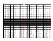
88 • APEx Conversion Tables<br />
ix
<strong>The</strong> Videc <strong>System</strong><br />
89 • Step Tablet Print Facsimiles<br />
95 • Index<br />
99 • Worksheets
Introduction<br />
Introduction<br />
<strong>The</strong> Gift<br />
Carried on the wings of light is the gift of vision.<br />
Artists who use light’s power to convey their<br />
feelings, involve themselves and their viewers in<br />
the complex realm of vision. Visual perceptions<br />
are often very different from the physical attributes<br />
of a scene. Yet, our perceptions are our personal<br />
reality.<br />
While photographs have the power to convey<br />
a strong sense of reality, the camera records only<br />
a few of the physical attributes of the scene. More<br />
important, the camera records a scene in a way that<br />
is fundamentally different from the impression we<br />
receive from our eyes.<br />
<strong>The</strong> scene before the camera, the captured<br />
image, and the interpreted image we create in the<br />
print are three worlds apart. To consciously make a<br />
photograph that transcends the ordinary, it is necessary<br />
for us to fully employ the inter-relationships<br />
between these worlds.<br />
Some photographers make prints with crystalline<br />
highlights and shadows brimming with detail.<br />
Others emphasize graphic form and shape by way<br />
of strong blacks and whites. Yet others trace images<br />
of delicate beauty within a narrow palate. Two<br />
questions naturally arise. How does a photographer<br />
deliberately set out to interpret something seen?<br />
What is the craft that will enable the photographer’s<br />
interpretation?<br />
<strong>The</strong> Search<br />
My search began at the age of 17. I came across<br />
the instruction manual for my dad’s vintage GE<br />
light meter. Toward the back of the booklet was a<br />
brief and tantalizing description of the relationship<br />
between exposure, development, and density. It was<br />
illustrated with a simple graph.<br />
Those few pages sparked my interest in the<br />
notion that the outcome of a photograph could be<br />
intentionally controlled. But there were still many<br />
unanswered questions. I wondered how the “relative<br />
exposure” numbers across the bottom of the graph<br />
related to the light in the scene, the meter reading<br />
and the f/stop and shutter speed on my camera.<br />
How did the density scale relate to the shadows and<br />
highlights in a print?<br />
So I studied the Zone <strong>System</strong>, read Ansel<br />
Adams, Minor White, Phil Davis and others, attended<br />
a highly regarded photography school and<br />
made many photographs. Yet the fundamental<br />
understanding that would link the elements of the<br />
process into a unified whole eluded me.<br />
I rarely made a truly excellent negative. It<br />
seemed to happen only when the sum of all my<br />
errors added up to “no net loss.” Sometimes the<br />
opposite happened; the accumulation of errors<br />
added up to serious problems. Occasionally they<br />
added up to a loss so severe that the negative was<br />
not worth printing.<br />
Surely, there had to be a means to fully control<br />
the photographic process using the wonderful<br />
meters, cameras, film and papers we now have<br />
available. With the help of many good friends,<br />
books, and a period of intense study, I worked out<br />
the principles of <strong>VIDEC</strong>.<br />
As I applied <strong>VIDEC</strong> to my own photography, I<br />
began to enjoy consistent success; making negatives<br />
that were the expression of my intentions. I learned<br />
how liberating it is to be master of your craft. <strong>The</strong>se<br />
principles have proven to be the key to producing<br />
negatives that are the best rendition of my vision. I<br />
trust it will do the same for you.<br />
<strong>The</strong> Problem<br />
If you have worked with black and white photography<br />
for very long, you know that changing the<br />
film development directly affects the effort it takes<br />
to print the resulting negatives. With some testing,<br />
trial and error, you learn which development scheme<br />
works best for certain subject conditions. You also<br />
learn which film speed works best.<br />
But the world is full of subjects of differing<br />
contrasts and greatly differing light conditions.<br />
For example, if we observe the effect of sunlight
<strong>The</strong> Videc <strong>System</strong><br />
on a subject at various times of the day, we will<br />
see luminous qualities ranging from subtle, under<br />
the soft diffuse light before dawn, to stark, under<br />
the hard-edge light of clear sky sun. However, to<br />
account for all the variations by trial-and-error testing<br />
would take an enormous amount of time, not<br />
to mention an unfailing memory to recall the vital<br />
bit when needed.<br />
Compounding the problem is the adaptability<br />
of our visual sense. Whether the lighting ratio is 1<br />
to 5 or 1 to 5,000, our eye (in combination with our<br />
brain) effortlessly gives us a satisfyingly full visual<br />
pallet of dark tones to light tones. Photographic<br />
materials by comparison do not automatically<br />
compensate for brightness differences.<br />
So how can limited experience cope with all<br />
the possibilities? When you encounter a new and<br />
exciting photo opportunity, how can you know that<br />
you will get the image on film the way you envision<br />
it? How do you design a test that gives you<br />
meaningful results? How can you produce a negative<br />
with optimum printing properties every time?<br />
A system that accounts for the worlds of vision,<br />
capture and display is required.<br />
Basic Attributes of an Exposure<br />
and Development <strong>System</strong><br />
Sophisticated exposure systems have been<br />
developed to address these questions with varying<br />
degrees of success. I believe a robust exposure and<br />
development system should have these attributes:<br />
• Simple enough to use when you are out taking<br />
pictures<br />
• Integrates visualization of the final print with the<br />
scene attributes<br />
• A c c o m m o d a t e s a n y f i l m a n d p a p e r<br />
combination<br />
• Precise enough to produce negatives that print<br />
within half a paper grade of the predicted density<br />
range<br />
• Self-referencing, that is it does not require<br />
reference to a calibrated standard; it does require<br />
that meters, timers, thermometers, etc. be linear,<br />
repeatable and reliable<br />
• Produces meaningful comparisons between<br />
tested films and papers<br />
• Accurately represents the density response of the<br />
film-developer combination as both exposure and<br />
the degree of development are changed<br />
• Be based on first principles and be scientifically<br />
defensible.<br />
Some Claims<br />
<strong>The</strong> Visually Integrated Development and<br />
Exposure Control (<strong>VIDEC</strong>) <strong>System</strong> satisfies the<br />
requirements of a robust exposure-development system.<br />
It meets these challenges by replacing trial and<br />
error with a system focused on the end result, the<br />
print. <strong>The</strong> tools of the system include a graph and a<br />
special gray scale, both of which you produce with<br />
your own equipment and work habits. Using these<br />
tools in a stepwise procedure, it is now possible<br />
and, more important, practical to evaluate any scene<br />
before the camera, envision a print of the scene,<br />
know which shutter speed and aperture to use,<br />
and know the degree of development the film will<br />
require. This well crafted negative not only has the<br />
optimum qualities to produce the envisioned print,<br />
but also gives substantial opportunity for alternate<br />
interpretations during the printing process.<br />
With <strong>VIDEC</strong> your mind’s visual power to<br />
observe and imagine, discriminate and invent,<br />
organize and envision, works in concert with the<br />
craft of photography. Paper and film are tested<br />
independently but in a way that allows any combination<br />
of paper and film to be linked. By coupling<br />
a particular print paper to a particular film using<br />
<strong>VIDEC</strong> methods, the outcome of a very wide range<br />
of exposure situations can be predetermined. You<br />
are empowered to execute your visual interpretation<br />
of a scene against the full range of photographic<br />
possibilities.<br />
<strong>The</strong> <strong>VIDEC</strong> method provides the tools to conquer<br />
four basic photographic challenges:<br />
• Visualizing how the tonal values in the scene will<br />
look in the print<br />
• Calculating the precise exposure<br />
• Determining the optimum degree of<br />
development<br />
• Matching any tested film to any tested paper.
Introduction<br />
Additionally, <strong>VIDEC</strong> helps you distinguish<br />
scenes that have photographic potential from those<br />
that do not. It enables you to predict how the range<br />
of scene brightness you perceive will actually appear<br />
in a print.<br />
<strong>The</strong> <strong>VIDEC</strong> <strong>System</strong> rests on the repeatability<br />
of the photographic process. From tests you make<br />
using your film and print paper, you will make a<br />
simple-to-use exposure/development graph. With<br />
this graph you can make informed choices when<br />
you evaluate a scene for its photographic potential.<br />
<strong>The</strong> outcome is a negative of optimum quality for<br />
achieving the desired outcome, a fine print.<br />
<strong>The</strong> <strong>VIDEC</strong> <strong>System</strong> accounts for all the major<br />
photographic variables - lens transmission and flare,<br />
light meter characteristics, film type, film development,<br />
print paper type and grade, enlarging lens,<br />
enlarger light source, print chemistry, and others.<br />
<strong>The</strong> system even accounts for variables that no<br />
manufacturer can control, that is, your photographic<br />
work habits, your agitation technique, water supply,<br />
and even your thermometer.<br />
<strong>The</strong> <strong>VIDEC</strong> <strong>System</strong> is solidly based on physical<br />
realities and clear terminology. Concepts such<br />
as exposure, contrast, and sensitivity take on precise<br />
meaning. <strong>The</strong> system reveals the actual performance<br />
of your photographic materials. For example,<br />
<strong>VIDEC</strong> methods reveal important tone reproduction<br />
characteristics of any tested film. Comparing<br />
these characteristics enables the photographer to<br />
choose the most suitable film for a desired style or<br />
particular application.<br />
Because the <strong>VIDEC</strong> <strong>System</strong> encompasses the<br />
fundamental principles of photography, it can be<br />
applied to the entire range of photosensitive materials<br />
and processes.<br />
<strong>The</strong> Challenge<br />
I challenge photographers to learn this new<br />
system. Make no mistake; <strong>VIDEC</strong> requires a degree<br />
of personal commitment. You need to have some<br />
experience developing film and making prints. You<br />
must have a good spot meter. You should also know<br />
how to plot a graph or be willing to learn. If you read<br />
the book, complete the exercises, and test your own<br />
materials, I am confident that your commitment will<br />
be rewarded with excellent results.<br />
<strong>The</strong>se are the major tasks you will accomplish:<br />
• You will start using the system with the tools I<br />
provide in this book<br />
• You will learn the system, its logic, and<br />
language<br />
• You will print a Step Tablet Print for the paper(s)<br />
you intend to use<br />
• You will test the film(s) you intend to use and<br />
produce your own iso-density graph<br />
• You will use <strong>VIDEC</strong> with your own iso-density<br />
graph and STP, evaluating the scene and carefully<br />
recording the information and your choices<br />
• You will create images that faithfully convey<br />
your intent by applying the <strong>VIDEC</strong> method to your<br />
unique sense of vision.<br />
Navigating the Book<br />
I want you to use the <strong>VIDEC</strong> system so the<br />
next chapter is a complete do-it-yourself tutorial.<br />
Most people get a solid, intuitive feel for the system<br />
on the first try.<br />
A discussion of the visual foundation of<br />
<strong>VIDEC</strong> follows. <strong>The</strong> APEx system of simplifying<br />
exposure calculations is next, then the sections on<br />
testing paper and film and drawing the iso-density<br />
graph. <strong>The</strong> glossary is arranged in tutorial sequence;<br />
that is, the definitions are arranged to build your<br />
understanding of photographic principles and the<br />
specifics of the <strong>VIDEC</strong> system. <strong>The</strong> terms are also<br />
indexed alphabetically. <strong>The</strong> final section is a terse,<br />
technical description of the system. <strong>The</strong> appendix<br />
has a description of how to use your spot meter as a<br />
densitometer and some other information that may<br />
be of interest to you.<br />
Feel free to skip around if you wish. If you find<br />
a term you don’t understand, look in the glossary.<br />
All the illustrations in the book were made using<br />
<strong>VIDEC</strong>.<br />
Let us begin!
<strong>The</strong> Videc <strong>System</strong>
Chapter 1<br />
Chapter 1 Quick Start<br />
Using the <strong>VIDEC</strong> <strong>System</strong><br />
It’s time to give it a try! Follow the instructions<br />
to get a feel for how the system works. Don’t worry<br />
that you haven’t tested your film and paper yet. <strong>The</strong><br />
information I’ve provided will give you results good<br />
enough to experience the benefits of the system. Go<br />
ahead; give it a try!<br />
What You will Need<br />
• Film – Kodak T Max 100 or Ilford Delta 100<br />
in the size for your camera (Roll or Sheet as<br />
needed)<br />
• A spot meter to evaluate the light in the scene<br />
• A few exposure record sheets (feel free to make<br />
copies of the one provided at the back of the book)<br />
and a pencil<br />
• <strong>The</strong> Iso-density Graph for the film you have<br />
chosen (found in the appendix)<br />
• Fresh developer (D-76 for T Max 100, DD-X<br />
for Delta 100)<br />
• <strong>The</strong> Step Tablet Print (STP) - for now use the<br />
facsimile STP found in the appendix<br />
it a straightforward photograph, not too close, normal<br />
focal length lens, no filters, and bright enough<br />
for your spot meter to read the darkest area in the<br />
scene.<br />
2) Set the spot meter to ISO/ASA 100. If your<br />
Follow these Instructions<br />
1) Find a subject that won’t move and a time<br />
of day when the light won’t change rapidly. Make<br />
meter allows, set it to read directly in EV units.<br />
When the meter is set for ISO/ASA 100, the EV<br />
reading is the same as the Luminance Value (LV),<br />
which is the measure of an area’s brightness.<br />
3) Analyze the scene by identifying the important<br />
light-toned areas and dark-toned areas in the<br />
scene. Scan the scene with the spot meter. Evaluate<br />
several areas in the scene. Record these values on<br />
the Exposure Record Sheet.<br />
4) Record the basic information on the Expo-
<strong>The</strong> Videc <strong>System</strong><br />
sure Record Sheet. First circle the film type you<br />
will be using. <strong>The</strong>n circle the print paper on which<br />
you will print this scene. <strong>The</strong> #2 grade of any good<br />
6) Pick the most important dark-toned area in<br />
the scene and compare it to the step tablet print.<br />
From the Step Tablet<br />
Print choose the shade<br />
of gray that you want<br />
that important dark-toned<br />
area to look like. Again,<br />
make a meter reading of<br />
that area and put a tick<br />
mark on the LV Ruler<br />
printed on the edge of the<br />
Exposure Record Sheet.<br />
Write the Step Number<br />
paper will work fine.<br />
5) Pick the most important light-toned area<br />
and compare it to the Step Tablet Print. From the<br />
Step Tablet Print choose<br />
the shade of gray that you<br />
want that important lighttoned<br />
area to look like.<br />
Make a meter reading of<br />
that area and put a tick<br />
mark on the LV Ruler<br />
printed on the edge of the<br />
Exposure Record Sheet.<br />
Write the Step Number<br />
from the STP associated with this reading. Jot a<br />
brief description of the measured area beside the<br />
tick mark.<br />
7) Find the exact exposure and development<br />
time on the Iso-density Graph.<br />
Lay the LV ruler over the Iso-density Graph.<br />
Find the LV for the dark-toned area and place it so<br />
from the STP associated with this reading. Jot a<br />
brief description of the measured area beside the<br />
tick mark.
Chapter 1<br />
that it touches the Step Line it corresponds to. For<br />
example, if you selected step 3 for the dark shade<br />
and that dark area reads LV = 10.3, then lay the 10.3<br />
on the ruler over the Step Line marked “3”.<br />
Without moving the LV ruler, find the LV for<br />
the light-toned area on the LV ruler. <strong>The</strong>n look for<br />
its corresponding Step Line. Now move the LV<br />
ruler right or left as needed to make the light-toned<br />
area LV and the dark toned-area LV touch the corresponding<br />
step lines simultaneously.<br />
8) Being careful not to move the ruler, read<br />
off the development time where the edge of the<br />
LV Ruler intersects the development axis. In this<br />
any combination of AV and TV from the left-most<br />
columns that adds up to EV’. Circle your choices.<br />
9) Make the exposure, then double-check your<br />
readings and calculations. If you are using sheet<br />
film, record the film holder number on the <strong>VIDEC</strong><br />
<strong>System</strong> Exposure Record.<br />
If you are using roll film, continue to find scenes<br />
to photograph and finish off the roll. Obviously, you<br />
are committed to using the first development time<br />
chosen. Continue to use that development time but<br />
use the iso-density graph to choose the exposure.<br />
example, rounding up slightly gives 13 minutes.<br />
EV’ is read off the LV Ruler where the RV<br />
= 0 line intersects. In this example, rounding up<br />
slightly gives 13.3.<br />
Record the development time by circling the<br />
time at the bottom of the exposure record sheet.<br />
Record EV’ in the calculation column.<br />
To figure the f/stop and shutter speed, pick
<strong>The</strong> Videc <strong>System</strong><br />
Evaluate the scene as just described and, without<br />
regard to where the high values will fall, use the<br />
exposure indicated on the iso-density graph based<br />
on the dark values.<br />
10) Process your film for the determined time<br />
at the temperature and dilution indicated on the<br />
Iso-density Graph. Use your normal technique for<br />
agitation and other processing steps.<br />
11) Make a straight print on a normal contrast<br />
grade of paper.<br />
Do the shades of gray in the print look appropriate?<br />
Did the shadow detail print the way you predicted?<br />
Were any highlights muddy gray or blown<br />
out? Now, compare these negatives and prints to<br />
others you’ve made in the past. Was getting a decent<br />
first print difficult from the <strong>VIDEC</strong> negatives? Do<br />
you think that it will be easier to make a good final<br />
print from the <strong>VIDEC</strong> negatives?<br />
You may be startled by a few things. First,<br />
a <strong>VIDEC</strong> negative may look under exposed or<br />
under developed. Don’t be put off, it will print just<br />
fine. Second, as you make more photographs with<br />
<strong>VIDEC</strong>, you may find that most of the development<br />
times are near the extremes. Again, don’t worry. If<br />
your <strong>VIDEC</strong> negatives make good prints, the system<br />
is working and conventional wisdom is falling<br />
by the wayside.
Chapter 1<br />
Due to limitations of the reproduction process, these are not perfect representations of the originals.<br />
It is left to you to make your own step tablet print on each paper you use. See Chapter 10 for details.<br />
<strong>The</strong> originals of the above step tablet prints were printed from a Kodak #2 Step Tablet Negative (0.15<br />
density increment) by enlargement with a condenser light source with a #2 filter onto Ilford MultiGrade<br />
Fiber Base Glossy paper.<br />
Additional copies can be found in the Appendix.
10<br />
<strong>The</strong> Videc <strong>System</strong>
Chapter 1<br />
11
12<br />
<strong>The</strong> Videc <strong>System</strong>
Chapter 2<br />
Chapter 2 Effective Relationship<br />
Mere Shades of Gray<br />
Master photographers excel at making all<br />
the tones in the print work together to achieve<br />
the response they want from the viewer. Effective<br />
relationship is the sublime visual effect caused by<br />
the shades of gray in a print. It is a visual event<br />
that occurs when the shades of gray in the print<br />
give rise to a strong response. <strong>The</strong>se visual cues<br />
may include the presence of detailed shadows, a<br />
textured white, a skin tone, or other anchor point.<br />
When the visual cues elicit the desired response<br />
from the viewer, we say the shades of gray are in<br />
effective relationship.<br />
<strong>VIDEC</strong> facilitates achieving effective relationship<br />
at two occasions in the photographic process:<br />
when the negative is made and when the print is<br />
made. At the time you make the photograph, you<br />
translate the scene luminances to the tonalities of<br />
the print through the intermediate stage of the photographic<br />
negative. Obviously making the negative<br />
precedes making the print by hours, days, or (too<br />
often in my case) weeks. But such is the power of<br />
the <strong>VIDEC</strong> system that you can explore the possibilities<br />
well after the photograph is taken.<br />
Let’s perform an exercise now to refine your<br />
personal sense of effective relationship.<br />
An Exercise for the Visual Sense<br />
This exercise will sharpen your understanding<br />
of how shades of gray relate to each other in a black<br />
and white print. Find the Step Tablet Print that came<br />
with this book. Now find several photographs that<br />
reflect your taste. <strong>The</strong>y should be original prints<br />
or very good reproductions from a fine book or<br />
calendar. We will ignore for the moment that the<br />
photographer may have burned, dodged, bleached,<br />
masked or otherwise manipulated areas of the print.<br />
For now we are interested in what works visually,<br />
not how it was done.<br />
Find a comfortable place with strong lighting.<br />
Lay the Step Tablet Print over the print and move<br />
it around. Compare the individual shades of gray<br />
on the Step Tablet Print to important areas in the<br />
photographs. Be sure to compare skin tones, the<br />
highlight on the cheek, and the shadow under the<br />
jaw, dark and light objects, grass, bark, concrete,<br />
clouds, water, or whatever else is important to you.<br />
Look at areas that are situated in direct light as well<br />
as in shadow. Look at textures and think about the<br />
properties of light that caused them to be revealed.<br />
Look very closely for fine detail revealed by contrasting<br />
shades.<br />
Observe the balance of values in a good highkey<br />
print, then compare your observations to the<br />
balance in a low-key print. (A high-key photo is one<br />
in which most of the shades of gray are very light;<br />
e.g., a fair-complected ballerina in a white outfit<br />
against a white background. A low-key photo is one<br />
in which most of the shades of gray are very dark.)<br />
Note how the tonal range affects the emotional<br />
impact of the print. What emotional responses did<br />
you experience as you observed high- and low-key<br />
photographs?<br />
How many sources of light can you find in<br />
each photograph? Do they cast sharp or diffuse<br />
shadows? Perhaps the photograph is illuminated<br />
with both sharp and diffuse light sources? How<br />
close are the sources? Does fine detail play a role<br />
in the impression the print makes?<br />
Were you surprised by any of your observations?<br />
Was foliage lighter or darker than you expected?<br />
Were skin tones more complex than you<br />
thought? Did you find a pure white and a deep<br />
black in all of the photographs? Have you found any<br />
prints that had neither a pure white nor a total black,<br />
yet were visually effective? Did any of the prints stir<br />
your desire to make new photographs with a visual<br />
interpretation you have not yet tried?<br />
If you observe a number of prints over a period<br />
of time, you will gain an appreciation for the effective<br />
relationship between shades of gray representing<br />
highlights and shadows, skin tones, clouds,<br />
metal, etc. By making this kind of observation an<br />
ongoing effort, you will strengthen your own sense<br />
13
<strong>The</strong> Videc <strong>System</strong><br />
of effective relationship. In time, your feel for effective<br />
tonal relationships will become intuitive. This<br />
finely tuned sense will greatly aid your ability to see<br />
beyond the expected, creating photographs that will<br />
astonish your audience. This exercise is especially<br />
powerful if you practice it regularly.<br />
<strong>The</strong> Step Tablet Print – the Key<br />
to <strong>VIDEC</strong><br />
<strong>The</strong> Step Tablet Print (STP) is a portable visual<br />
record of the shades of gray that a particular photographic<br />
paper will produce. <strong>The</strong> STP gives you<br />
specific information about how your photographic<br />
paper behaves.<br />
It enables the “Visually Integrated” part of<br />
the <strong>VIDEC</strong> acronym. As you strive for effective<br />
relationship in the photo opportunities that pass<br />
your way, you can correlate the values you see in<br />
the scene with shades of gray on the print paper you<br />
choose. <strong>The</strong> other <strong>VIDEC</strong> tools will tell you what<br />
exposure and development to give the film to get<br />
an optimum negative for that paper. (Refer to the<br />
master illustration in Chapter 1.)<br />
<strong>VIDEC</strong> does not work without the Step Tablet<br />
Print. Not just any gray scale will do. <strong>The</strong> best one<br />
to use is the one you make in your own darkroom<br />
on your favorite paper(s). <strong>The</strong> procedure for making<br />
your own is described in Chapter 10.<br />
<strong>The</strong> Dynamic Range of the<br />
Human Vision <strong>System</strong><br />
We would be extinct if we could not extract<br />
more from the visual world than a camera can record.<br />
Our vision system takes cues from the scene<br />
and creates for us the sensations of color, depth,<br />
scale, brightness, motion and others. Such is the<br />
power of vision that a person with sight in just one<br />
eye can still perceive depth. In short, we carry a very<br />
sophisticated, real-time image processing computer<br />
right between our ears.<br />
Cameras, like our eyes, capture light rays<br />
and organize them into images with remarkable<br />
properties. Unlike human vision, cameras are<br />
mechanically literal. <strong>The</strong> laws of physics strictly<br />
govern their workings. Let us explore some of the<br />
important relationships between the scene we see<br />
and the image in the camera.<br />
To clarify, the term for the light we measure<br />
with a photographic light meter is luminance. It<br />
can be light that is either reflected from a surface<br />
or emitted from it. <strong>The</strong> impression that luminance<br />
makes on our vision is called brightness.<br />
<strong>The</strong> way we perceive light and dark is relative.<br />
Black to a physicist is the absence of all light. But to<br />
our visual sense, an area will appear black if it is a<br />
certain amount less bright than the area around it.<br />
That is, the impression of black is relative. For example:<br />
a black cat’s fur reflects a small but measurable<br />
amount of light. It is always a fixed percentage<br />
of the light falling on the fur. But we perceive the<br />
cat as black relative to its surroundings.<br />
A television set in the normal light of the living<br />
room provides a good example of brightness perception.<br />
If we look at the screen when it is turned off,<br />
it appears to be a dark gray tone. We can measure<br />
the luminance of the dead screen, that is, the room<br />
light reflected from it.<br />
Now, without changing the room lighting,<br />
we turn on the set and look at the TV picture. We<br />
will see a full range of tones from light to dark. If<br />
we measure an area on the screen that looks to be<br />
black, it will have at least the same luminance value<br />
as when it was turned off. Our vision system has<br />
interpreted the visual cues, specifically the range<br />
of luminances on the screen, as having a range of<br />
brightness from black to white.<br />
<strong>The</strong> Perception of Brightness<br />
Your visual system always works to put tonal<br />
values in effective relationship no matter how great<br />
or small the brightness differences may be. Let’s<br />
consider two scenarios.<br />
Some people are sitting in a lunchroom with<br />
sunlight streaming in from a large window to the<br />
left. A woman is sitting in front of me wearing a<br />
brilliant white, textured satin blouse. Just beyond<br />
her is a black woman facing the sun; her hair is in<br />
shadow. I can see detail in the blouse and detail in<br />
the dark black hair. <strong>The</strong> measured difference be-<br />
14
Chapter 2<br />
tween the brightest and darkest area is 10 LV units<br />
(stops) or 1,024:1. Contemporary slide films capture<br />
around 6 LV units or 64:1. My eye, as would yours,<br />
easily encompassed the full range of the scene.<br />
While at a motel I saw an interesting shape<br />
and form in the design of a pristine white shower<br />
stall. I decided to take a photograph. I measured<br />
the luminances with my spot meter. It couldn’t be!<br />
<strong>The</strong> brightest area was only 1.1 LV units (2.14:1)<br />
brighter than the darkest shadow in the scene and<br />
yet I perceived a wide brightness variance in the<br />
curves of the tub.<br />
<strong>The</strong>se two scenarios show a world full of extremes<br />
that our visual apparatus handles with ease.<br />
What all good photographers master is getting the<br />
shades of gray in effective relationship across a wide<br />
range of circumstances. Recognizing that there is a<br />
difference between the visual impression of a scene<br />
and its physical attributes is the first step.<br />
<strong>The</strong> Problem is Key to the<br />
Solution<br />
Human vision gives priority to interpreting the<br />
luminance differences between objects in our field<br />
of vision. A camera cannot interpret; it can only<br />
project a faithful image of the scene luminances<br />
onto the film. But the film and the print paper add<br />
their own flavor, that is tonal transformation, to the<br />
resulting print. Imagine if we could devise a way<br />
to see through the intermediate steps to the print;<br />
somehow accounting for the tonal transformations<br />
the film and paper will cause. Imagine a direct<br />
method, a sort of a bridge, to reliably get a truly<br />
optimum negative. This is exactly what the <strong>VIDEC</strong><br />
<strong>System</strong> empowers you to do.<br />
As the Quick Start exercise demonstrates,<br />
the brightnesses in the scene can be correlated to<br />
intentionally chosen grays on the print paper (the<br />
step tablet print). At the same time, the optimum<br />
exposure and development time are calculated using<br />
the iso-density graph. Combining your knowledge<br />
of effective relationship with a worthy subject, you<br />
will master the medium.<br />
Know Your Limits<br />
While human vision has remarkable range, it<br />
does have limits. Our ability to distinguish small<br />
luminance differences decreases as the illumination<br />
decreases. In bright sunshine we can see the<br />
individual hairs on a black cat but under the dim<br />
light of the moon we can only see the gross form<br />
of the cat. Our perception varies between these two<br />
extremes.<br />
This has important implications for the photographer.<br />
First, it points to the problem of anticipating<br />
the effect of light. In some situations, we can see<br />
a range far greater than we can record easily with<br />
a camera. In others, we can see subtleties of color<br />
and shade that may translate into a bland-looking<br />
photograph. We must learn how our eyes interpret<br />
the scene. We have to recognize the conditions that<br />
make good or bad photographs no matter what our<br />
eyes are telling us.<br />
Second, it points to the challenge of interpretation.<br />
Do we choose to reveal the subtle shades of<br />
the black cat’s fur or do we envision a mysterious<br />
silhouette?<br />
Third, it points to the problem of the viewing<br />
conditions when the scene we are observing is a<br />
photograph. Photographs with large areas of dark<br />
detail may look fine under strong illumination but<br />
appear heavy and lifeless under weaker illumination.<br />
In fact, a print must be made with the final<br />
viewing conditions in mind. Two outstanding books<br />
on the subject of printing are <strong>The</strong> Print by Ansel<br />
Adams and Kodak’s Quality Printing which is out<br />
of print at this writing.<br />
This brief discussion of brightness and luminance<br />
touches the study of human visual perception<br />
for our immediate needs only. <strong>The</strong>re are other<br />
areas that are of interest to the photographer but are<br />
beyond the scope of this book.<br />
Envision It Outside!<br />
Using the same STP you used to examine<br />
prints, go outside and examine a variety of scenes.<br />
Bring a friend along and find a scene you might<br />
want to photograph. Pose your friend in the scene.<br />
Imagine that you are going to take this picture.<br />
What shade of gray from the STP will you associate<br />
15
<strong>The</strong> Videc <strong>System</strong><br />
with the skin tone of your subject, or the highlight<br />
on the cheek, or the shadow side of the face? What<br />
shade of gray will you associate with the deepest<br />
shadow in the scene or with the brightest highlight?<br />
What of the values in the background? How do the<br />
relationships change if you move from direct sun<br />
to open shade?<br />
<strong>The</strong>se are the very associations that connect the<br />
scene with your intention of how the print should<br />
look with the exposure and development the negative<br />
must receive to be printable. Your finely tuned<br />
aesthetic sense will be coupled to the best photographic<br />
craftsmanship using the <strong>VIDEC</strong> system.<br />
16
Chapter 3<br />
Chapter 3 <strong>The</strong> Film-Based<br />
Photographic Process<br />
<strong>The</strong> Scene and its Optical Image<br />
Have you ever burned a leaf with a magnifying<br />
glass? <strong>The</strong> magnifying glass functioned as a<br />
simple lens, collecting and focusing the radiation<br />
of the sun. <strong>The</strong>re was enough energy in that image<br />
of the sun to raise the temperature of the leaf and<br />
cause it to burn. In the same way, the lens on our<br />
camera focuses the radiation reflected or emitted in<br />
a scene onto the film. <strong>The</strong> miracle of photography<br />
is that it takes only a small amount of light energy<br />
to make a fine photograph; a tiny fraction of the<br />
energy needed to burn the leaf!<br />
Light has a physical nature; it is energy. Physicists<br />
note that one of the properties of energy is the<br />
ability to cause change. We know from our daily<br />
experience that plants use light to make their own<br />
food through the process of photosynthesis. <strong>The</strong><br />
color in the curtains and couch fade when exposed<br />
to the strong light of the sun. <strong>The</strong> effect of sun<br />
exposure on human skin ranges from the healthful<br />
production of vitamin D to severe sunburn.<br />
Light also causes changes within our eyes<br />
as the lens focuses images on the retina. <strong>The</strong>se<br />
changes are translated by our nervous system into<br />
the sense we call vision. Our eyes constantly refresh<br />
themselves so we see the changing world around<br />
us as it happens.<br />
Light is the form of energy that makes photography<br />
possible. <strong>The</strong> film and paper we use are<br />
coated with materials that are invisibly changed by<br />
the power of light. <strong>The</strong>se changes are made visible<br />
and permanent by chemical processes. Virtually<br />
all films and papers make use of the light sensitive<br />
nature of certain chemical compounds, the silver halides.<br />
<strong>The</strong>se silver halides are suspended in gelatin<br />
and coated onto a film or paper base. <strong>The</strong> coating<br />
is called the emulsion.<br />
Fortunately for us, the whole process is predictable<br />
and repeatable. We can test and measure how a<br />
film responds to light by using a plan to standardize<br />
our procedures and to interpret the results.<br />
Exposure<br />
When a photographic material is exposed to<br />
light, the photosensitive material is changed in<br />
relation to the amount of light falling on it. At this<br />
stage, the change is invisible or latent. It takes a<br />
certain amount of exposure before any measurable<br />
change occurs. But once the emulsion receives that<br />
minimum amount of light, the more light that falls<br />
on the photosensitive material, the more the material<br />
is changed. Once all the photosensitive material<br />
has been changed, adding more exposure has no<br />
further effect.<br />
Processing<br />
To make the latent image visible and permanent,<br />
we use a chemical process called development.<br />
<strong>The</strong> chemical called developer changes the exposed<br />
silver halide particles into metallic silver without<br />
affecting the unexposed particles.<br />
Developer also has the effect of amplifying the<br />
exposure. <strong>The</strong> small change caused by exposure<br />
to light is made many times more effective by the<br />
action of the developer. <strong>The</strong> amount of amplification<br />
is dependent on the chemical properties of the<br />
developer.<br />
When film is placed in developer, the exposed<br />
silver halides begin to be converted. <strong>The</strong> longer a<br />
negative is developed, the greater the number of<br />
exposed silver halide particles will be changed. <strong>The</strong><br />
strength of the specific developer formula, that is its<br />
concentration also affects how fast the development<br />
process will proceed. Development time, developer<br />
temperature and concentration affect the degree of<br />
development. Thus both exposure and degree of<br />
development influence the amount of silver halide<br />
converted to metallic silver.<br />
17
<strong>The</strong> Videc <strong>System</strong><br />
When the desired degree of development has<br />
been reached, the film or paper is put in a weak<br />
acid solution called stop bath. Its job is to stop the<br />
action of the developer and extend the life of the<br />
next chemical. Some photographers use a water<br />
rinse instead of stop bath; this slows development<br />
substantially by diluting the developer.<br />
At this point in the process, both the undeveloped<br />
silver halides and the metallic silver are present<br />
in the emulsion. <strong>The</strong> developed image is barely<br />
distinguishable and the undeveloped silver halide is<br />
still light sensitive. To obtain a useful negative, the<br />
undeveloped silver halide must be removed. <strong>The</strong><br />
chemical, which dissolves away the undeveloped<br />
silver compounds, is called fixer (to fix or make<br />
permanent). Like sugar in warm water, the halides<br />
dissolve away into the fixer. After fixing, only the<br />
silver remains. <strong>The</strong> final steps are to wash the fixer<br />
out of the emulsion and dry the film.<br />
In summary, the amount of metallic silver<br />
remaining in the film after processing is related<br />
directly to the exposure and development. <strong>The</strong><br />
remaining silver forms the image we can view,<br />
project, and print. <strong>The</strong> measure of the visible image<br />
is called optical density.<br />
Density, the Response of Film<br />
to Exposure and Development<br />
What we see when we look through a negative<br />
is light modulated by density. If you compare<br />
the negative to the scene, you will see an obvious<br />
correspondence. Light objects in the scene are dark<br />
in the negative. Likewise, dark objects in the scene<br />
appear light (or clear) in the image on the negative.<br />
Density is the response of photographic material to<br />
exposure and processing.<br />
<strong>The</strong> density that results from exposure and development<br />
is easily measured. With careful testing<br />
and record keeping, we can predict how our film<br />
will respond to different amounts of light.<br />
<strong>The</strong> ability to predict the response of photographic<br />
materials is crucial to any exposure/development<br />
system. Sensitometry is the science of<br />
measuring photographic response; that is, optical<br />
density as the response to both exposure and degree<br />
of development.<br />
When light strikes most materials it is absorbed,<br />
reflected, or transmitted. Usually it is a<br />
combination of these three. When light strikes the<br />
silver remaining in our processed film, a small<br />
amount is reflected, some is transmitted, some scattered,<br />
and the balance is absorbed. When we hold a<br />
negative to the light, we can see the image because<br />
the varying amounts of light-absorbing silver correspond<br />
to the intensity of the light patterns imaged<br />
onto the film.<br />
<strong>The</strong> light that makes it through the negative<br />
can be measured; here’s how. If we measure how<br />
much light is striking the film and compare it to the<br />
amount being transmitted, we obtain a value called<br />
optical density. Density is a measure of the fraction<br />
of light absorbed by the negative.<br />
Measuring Optical Density<br />
A device called a densitometer is used to mea-<br />
18
Chapter 3<br />
sure the optical density of a negative. A densitometer<br />
has a stable light source, a probe to examine<br />
a small area of the negative, and the electronics to<br />
measure the light. Densitometers read out directly<br />
in optical density units.<br />
Good densitometers are not cheap, but they<br />
are a common tool in professional processing labs.<br />
Many amateur photographers find them a valuable<br />
tool too. To make use of the <strong>VIDEC</strong> <strong>System</strong> you<br />
will need access to a densitometer. If you do not<br />
have access to one, there are ways of using a good<br />
spot meter for the purpose (see Appendix). Since<br />
you need a spot meter to make readings when taking<br />
pictures, you can get double duty from your<br />
investment.<br />
How the Density Numbers<br />
Work<br />
<strong>The</strong>re is an important relationship between<br />
the values of optical density. First, a density of 0.0<br />
means that no light was absorbed, reflected or scattered;<br />
all the light was transmitted. A density of 0.3<br />
means that one half of the light was transmitted;<br />
half the light was absorbed. A density of 0.6 means<br />
that one quarter of the light was transmitted; three<br />
quarters was absorbed. A density of 0.9 means that<br />
an eighth of the light was transmitted; seven eighths<br />
was absorbed.<br />
Each increase in optical density of 0.3 means<br />
that one half as much light was transmitted. Each<br />
decrease of 0.3 density means that twice as much<br />
light was transmitted. <strong>The</strong> amount of light transmitted<br />
must always be less than the amount of light<br />
falling on the negative.<br />
Just as a negative has density so does a photographic<br />
print; it is called reflected density. A<br />
processed photographic print is actually a negative<br />
lying in intimate contact with the surface of the<br />
paper. However, there is a big visual difference<br />
between film and paper.<br />
<strong>The</strong> light striking a negative passes through<br />
the emulsion just once. <strong>The</strong> light striking the photographic<br />
paper emulsion passes through the emulsion<br />
twice on its way to the eye. First it passes through<br />
the silver on its way to the paper base. <strong>The</strong>n it is<br />
reflected by the paper-base back through the silver<br />
to the eye. <strong>The</strong> density effect of the single layer is<br />
doubled.<br />
A densitometer that reads the densities of<br />
negatives is called a transmission densitometer. A<br />
densitometer that reads reflected densities is called a<br />
reflection densitometer. Some instruments combine<br />
both functions in one package.<br />
Making a Positive Print<br />
To make a positive print from a negative we<br />
need another negative working material. This is a<br />
clear cut case of two negatives making a positive.<br />
If we place a properly exposed and processed negative<br />
between an even light source and an unexposed<br />
negative material, the light from the source will be<br />
modulated by the negative: the dense areas holding<br />
light back resulting in light areas on the print and<br />
the clear areas allowing more light to pass resulting<br />
in dark areas on the print.<br />
A Special Case: Dye Images<br />
Color negatives, slides, prints, and chromogenic<br />
black and white films use silver compounds as<br />
the photosensitive detector but there is an important<br />
difference in the way the image is formed. <strong>The</strong><br />
exposed silver is removed during processing and<br />
special dyes are formed in its place to create the<br />
image we see. <strong>The</strong>se dyes absorb light like silver<br />
but do not scatter the light in the same way. <strong>The</strong><br />
reasons for this behavior are outside the scope of<br />
this book but the effects are accounted for in the<br />
normal <strong>VIDEC</strong> <strong>System</strong> testing procedure.<br />
<strong>The</strong> Fathers of Sensitometry<br />
In the early days of photography, the photographic<br />
process was not well understood. Many<br />
scientists studied photographic materials to learn<br />
the secrets of the new technology. In 1890, two<br />
scientists, F. Hurter and V. C. Driffield, made a<br />
major contribution to the science of photography,<br />
which today bears their names. By plotting a family<br />
of curves on a simple graph they showed the relationship<br />
between exposure, degree of development,<br />
and density. <strong>The</strong> curves are called the H&D curves<br />
19
<strong>The</strong> Videc <strong>System</strong><br />
or, interchangeably, the characteristic curves. <strong>The</strong><br />
<strong>VIDEC</strong> <strong>System</strong> rests on the foundation they laid.<br />
About Graphs and Formulas<br />
We can often use a formula to predict the result<br />
of some action. If you drive for two hours at 50 miles<br />
per hour, how far will you travel? We can calculate<br />
the answer easily. By applying the formula “distance<br />
= rate x time,” we know the answer is 100 miles.<br />
Other relationships are not as simple as our<br />
driving example. Sometimes it is just not possible<br />
to come up with a simple formula that will give us<br />
the answer. If we perform a test and collect the right<br />
data, however, we can plot the results on a graph<br />
and visualize the results. By simply connecting the<br />
dots, we can make a very close prediction of the<br />
in-between values.<br />
<strong>The</strong> complex relationship between exposure,<br />
development and density is best represented by a<br />
graph and is a good way to learn the characteristics<br />
of a film and put this knowledge to work. Graphs<br />
like the H&D curves above are useful because they<br />
tell us how the density changes when we change the<br />
exposure, development conditions, or both.<br />
<strong>The</strong>se curves reveal the sensitivity of the film.<br />
Examine the curves and you will find that the film<br />
has no sensitivity to exposures less than -5 RV units.<br />
As we increase exposure to -4 then to -3 we see the<br />
film respond with more and more density.<br />
<strong>The</strong> curves can be used in reverse. If we want to<br />
know how much exposure it takes to get a particular<br />
density at any of the tested development times, the<br />
curves will tell us. This intimate knowledge of the<br />
film combined with a simple way to test our print<br />
paper gives us the power to solve the old problem<br />
of how much exposure and development do I give<br />
my negative.<br />
We will extract the information needed to plot<br />
the Iso-density curves from the H&D curves. We<br />
will explore exactly how to do this in Chapters 9<br />
and 12.<br />
20
Chapter 4<br />
Chapter 4<br />
Good Negative Quality<br />
Good Quality is Relative<br />
A good negative is relative to the purpose of<br />
the photograph. It is relative to your way of looking<br />
at the world. It is relative to your print paper.<br />
Though it is an intermediate step to the final print,<br />
the characteristics of the negative are critical to the<br />
appearance of the final print.<br />
Personal interpretation plays an important role<br />
in determining desirable photographic qualities.<br />
<strong>The</strong> smooth, grainless tones of a large format negative<br />
are lovely, but the photojournalist may want<br />
the psychological punch of tight grain and strong<br />
contrast. Personal interpretation should drive the<br />
technical considerations.<br />
Traditionally negative quality has been judged<br />
by technical considerations such as graininess,<br />
fog, sharpness, density range, shadow detail and<br />
contrast. Note well that these technical qualities<br />
are all interrelated. If you attempt to maximize<br />
one, you may sacrifice another. <strong>The</strong> challenge is<br />
to optimize all the factors together to achieve your<br />
desired outcome.<br />
Optimization is the clear purpose of the<br />
<strong>VIDEC</strong> <strong>System</strong>. At the same time, <strong>VIDEC</strong> allows<br />
you to easily try new combinations of film and<br />
print paper. A good starting point for information<br />
about a film or paper is the manufacturer. Many<br />
of the major manufacturers publish useful guides<br />
that aid in selecting the best film and developer for<br />
a given application.<br />
Some Important Qualities of<br />
Negatives<br />
<strong>The</strong> more exposure a negative receives, the<br />
more grains of silver will be developed. <strong>The</strong> more<br />
grains of silver developed, the greater the appearance<br />
of graininess in the print. Thus, to minimize<br />
graininess, keep the exposure as low as possible.<br />
On the other hand, to obtain detail in the<br />
shadow regions of the print the negative must have<br />
adequate printing density that only results from<br />
adequate exposure. A particular film simply will<br />
not record light below a certain exposure. Efforts<br />
to reduce graininess by reducing exposure come<br />
head-to-head with the absolute need to give the film<br />
a certain minimum exposure.<br />
To make a print that achieves its full range of<br />
tonalities, the print paper must be exposed to just<br />
enough light to show detail in the highlights and<br />
not so much that the shadow detail turns black and<br />
empty. <strong>The</strong> difference between these two exposures<br />
is called the exposure range of the photographic<br />
paper.<br />
<strong>The</strong> difference between the shadow density<br />
and the highlight density of the negative has to<br />
match the exposure range of the print paper. A #2<br />
grade paper typically has an exposure range of 1.2<br />
log units (there is considerable variation from paper<br />
to paper). <strong>The</strong>refore the technically good negative<br />
should have a density difference of 1.2 density units<br />
between the deepest shadow and the brightest highlight.<br />
(See the technical description of <strong>VIDEC</strong> in<br />
Chapter 14 for a more detailed analysis of negative<br />
density range and print exposure range.)<br />
For low-contrast subjects (i.e., with a small<br />
scene luminance range), the degree of development<br />
may be increased to obtain the desired negative<br />
density range. <strong>The</strong> drawback is that increasing<br />
the degree of development increases the apparent<br />
graininess of the printed image.<br />
For high-contrast subjects (i.e., with a large<br />
scene luminance range), the degree of development<br />
may be reduced to obtain the desired negative density<br />
range. Reduced development has the effect of<br />
reducing the overall sensitivity of the film.<br />
With this understanding, we can construct a<br />
rationale for exposure and development. That is,<br />
21
<strong>The</strong> Videc <strong>System</strong><br />
we can select the optimum degree of development<br />
for the luminance difference presented by the scene<br />
and simultaneously choose the minimum exposure<br />
that will record the detail we want to capture.<br />
Remember that we are talking in a strict<br />
technical sense. While there are valid aesthetic<br />
and technical reasons for bending the rules, every<br />
serious photographer must consider these factors<br />
when learning to master the medium.<br />
Camera Settings and Exposure<br />
<strong>The</strong> word exposure is tossed around casually;<br />
too casually sometimes. Let me explain. Exposure<br />
is not “f/8 at 1/125 sec.” Those are only camera<br />
settings; the exposure controls. Exposure occurs<br />
when something is exposed to radiation for a period<br />
of time.<br />
In photography, the radiation is light and the<br />
something is film or paper. <strong>The</strong> longer the time,<br />
the greater the exposure. <strong>The</strong> stronger the light, the<br />
greater the exposure. <strong>The</strong> camera settings control<br />
the amount of exposure delivered to the film. You<br />
balance the f/stop against the shutter speed for<br />
the best visual effect (i.e., the sometimes-fiendish<br />
choice between motion stopping, depth of field, and<br />
optimum sharpness).<br />
If you were to photograph a building during<br />
the day in sunlight and then again when the sky<br />
is heavily overcast, the camera settings would be<br />
different. This is easily understood. <strong>The</strong>re is not as<br />
much light on the building when the sky is overcast<br />
as there is in the sunshine. To get the same effect on<br />
the film (density) at both times, the exposure to the<br />
film must be the same for both frames. Compared to<br />
the sunny day, you must either increase the aperture<br />
of lens or set the shutter for a longer time to deliver<br />
the same exposure to the film.<br />
About Film Speed<br />
Film speed is a number selected to achieve<br />
the highest likelihood of obtaining an acceptable<br />
photograph under a wide variety of conditions. <strong>The</strong><br />
light meter uses this number to calculate the f/stop<br />
and shutter speed.<br />
It was determined very early in the history of<br />
photography that the best strategy for reproducing<br />
a photographic image is to capture the scene on a<br />
low contrast material (photographic film) and print<br />
it on a high contrast material (photographic print<br />
paper). This approach minimizes the effects of<br />
over or under exposure and processing variations.<br />
So, with low contrast film, how do you choose the<br />
best exposure?<br />
A great deal of serious scientific study has<br />
gone into the process of determining film speeds.<br />
Manufacturers and standards bodies (ISO) use<br />
statistical methods to determine the luminance<br />
range of common pictorial situations, variations in<br />
processing from lab to lab, and variations between<br />
cameras. Processing parameters are specified. Add<br />
to this an understanding of what the general public<br />
considers to be an acceptable print and you have a<br />
“film speed”. At the end of this detailed process,<br />
the film manufacturer stamps the film box with<br />
the film speed.<br />
This statistical approach has strengths and<br />
weaknesses. For general-purpose photography, a<br />
properly determined film speed will ensure you are<br />
pleased with the family vacation photos. Film speed<br />
is also a good relative indicator of the suitability of<br />
a particular film to various lighting conditions.<br />
Outstanding Results<br />
But outstanding results in black and white photography<br />
are rare with the statistic-based approach.<br />
For the serious photographer, the conventional notion<br />
of film speed falls short of being useful for the<br />
range of conditions routinely encountered.<br />
<strong>The</strong> misapplication of film speed in other systems<br />
of exposure control often results in a gross<br />
misunderstanding of the fundamental photographic<br />
relationships. <strong>The</strong> effects of characteristic curve<br />
shape and the shift in sensitivity as development<br />
times are changed are utterly lost.<br />
<strong>The</strong> principles behind <strong>VIDEC</strong> avoid these<br />
complications, serving instead to clearly reveal<br />
the true nature of the photographic process. At the<br />
same time, <strong>VIDEC</strong> principles lead to unprecedented<br />
mastery of the medium.<br />
22
Chapter 5<br />
Chapter 5 Light Meters<br />
Introduction<br />
Light meters measure the light from a scene<br />
and return useful information to the photographer.<br />
Meters have three major parts — a light sensor, a<br />
display, and a calculator. <strong>The</strong> sensor detects the<br />
intensity of the light. <strong>The</strong> display gives an indication<br />
of how much light is falling on the sensor. <strong>The</strong><br />
calculator takes that readout and combines it with<br />
the film speed to give the camera settings (i.e., f<br />
stop and shutter speed). Some meters also have an<br />
optical aiming device.<br />
Modern meters take advantage of the power of<br />
light to change the behavior of certain materials. For<br />
example, when exposed to light, the metal selenium<br />
generates a small voltage. <strong>The</strong> compound, cadmium<br />
sulfide, changes resistance. In a charge-coupled device,<br />
exposure to light depletes a known electrical<br />
charge. In all these cases, changes are a function of<br />
light energy falling on the material. <strong>The</strong> change can<br />
be measured with sensitive electronic circuits and<br />
displayed in convenient units for our use.<br />
Meter Types<br />
<strong>The</strong>re are two general categories of photographic<br />
exposure meters — reflected and incident.<br />
Reflected light exposure meters are the type used<br />
in the <strong>VIDEC</strong> <strong>System</strong>, but it is useful for us to<br />
study both.<br />
Incident Meters<br />
Incident-light exposure meters measure illuminance.<br />
Illuminance is the intensity of the light<br />
falling on the subject. Incident meter readings are<br />
based on the assumption that light reflected from<br />
the lightest and darkest objects in the scene will<br />
fall within a certain range. <strong>The</strong> exposure settings<br />
calculated by an incident meter are based only on<br />
the intensity of the light falling on the subject. It<br />
does not matter that the subject may be black velvet<br />
or white satin. An incident meter only “sees” the<br />
light source; it does not “see” the subject.<br />
Readings must be taken from the subject position.<br />
If you cannot physically get close to your<br />
subject, you must simulate the conditions to obtain<br />
a valid reading.<br />
An incident meter can be used to measure the<br />
contrast between the highlight side and the shadow<br />
side of the subject. But an incident meter cannot account<br />
for the brightness of the white satin and black<br />
velvet in the shadows. It cannot directly measure<br />
the luminance of specific areas in the scene. This<br />
limitation makes the incident meter unsuitable for<br />
the <strong>VIDEC</strong> <strong>System</strong>.<br />
Professional photographers often use incident<br />
meters because they give good information about<br />
the intensity of the various light sources in a scene.<br />
<strong>The</strong>y provide a consistent means to record a scene<br />
without having to interpret every tonality. Careful<br />
photographers test their incident meters and films<br />
to learn just what film speed to use to get the best<br />
results.<br />
<strong>The</strong> Reflected-Light Meter<br />
Reflected-light exposure meters measure luminance<br />
(LV), the light reflected or emitted from the<br />
area in the scene before it. In use, a reflected meter<br />
is pointed at the subject from the camera position.<br />
All of the luminance sources within the view<br />
of the meter are averaged in the reading. Many hand<br />
held meters have an angle of acceptance of 10 to 15°.<br />
Meters with a small angle of acceptance (usually 1°)<br />
23
<strong>The</strong> Videc <strong>System</strong><br />
are called spot meters. Spot meters use a low power<br />
telescope as an aiming device to show the exact area<br />
being measured. Other meters encompass angles of<br />
view up to 30° and are simply pointed in the general<br />
direction of the subject.<br />
<strong>The</strong> <strong>VIDEC</strong> method works best with a 1° spot<br />
meter because the 1° angle is usually small enough<br />
to isolate the important luminances in a scene.<br />
Reflected light exposure meters are more complicated<br />
to use than incident meters. As you know,<br />
a scene will have light, medium and dark objects,<br />
highlights and shadows. So where do we point the<br />
meter? With some experience we learn to average<br />
these readings and “place” the exposure. But there<br />
is another way to use the spot meter that achieves<br />
a high degree of precision.<br />
Because spot meters give one reading for each<br />
area you point it at, that reading is directly related<br />
to the luminance of that area. By making a simple<br />
adjustment, any good quality spot meter can be used<br />
to give accurate luminance information for individual<br />
areas in the scene. In the <strong>VIDEC</strong> system, this<br />
information is used to determine both the correct<br />
exposure and the optimum degree of development<br />
for the negative. <strong>The</strong> chapter on APEx describes<br />
the entire procedure.<br />
Using the Reflected Light Meter<br />
For a reflected meter reading to be accurate,<br />
the reading must be made from the camera position.<br />
<strong>The</strong> closer the meter is to the lens the better. For<br />
example, glossy surfaces reflect radically different<br />
intensities depending on the observer’s position.<br />
A person looking at a shiny car may see the deep<br />
color of the paint job; another person standing just<br />
a step away may only see the glare of the sun. If<br />
you make a reflected reading too far from the camera<br />
position, you may be reading a reflection that<br />
is not seen by the camera or vice versa. (A clever<br />
pro taught me a neat trick for cameras with both a<br />
removable lens and film back. Once the camera is<br />
set for the view you want, just remove the lens and<br />
the back and make your readings right through the<br />
camera body.)<br />
Many reflected meters also display the readings<br />
as an EV number. EV numbers are very useful in<br />
the <strong>VIDEC</strong> <strong>System</strong>. <strong>The</strong>y are explained in depth<br />
in Chapter 7.<br />
Some Problems With Light<br />
Meters<br />
Wonderful as they are, exposure meters are<br />
prone to certain problems that are matters of design,<br />
construction and adjustment.<br />
A good exposure meter will have proper spectral<br />
sensitivity. That is, it will respond to different<br />
colors of light the way the photographic film does.<br />
However, some meters respond to infrared or ultraviolet<br />
light as well as to visible light. Neither our<br />
eyes nor normal film are sensitive to this light. If a<br />
subject is reflecting or emitting this non-visible light<br />
and the meter reads it, the reading will be incorrect.<br />
This is a very difficult problem to detect, and it can<br />
cause havoc when using the meter to test a film.<br />
A meter may be out of calibration if it gives a<br />
reading that is too high or too low. Usually, a simple<br />
adjustment made by a competent repairman will fix<br />
the problem. Or, the photographer can compensate<br />
by adjusting the film speed on the meter. Some<br />
meters have an adjustment accessible to the user.<br />
Be cautious if you make your own adjustments; you<br />
may not be able to restore the meter to its original<br />
setting.<br />
When a meter reads one luminance correctly<br />
but not another, the meter is said to be non-linear.<br />
For example: if a white wall in direct sunlight is 8<br />
times brighter than the wall on the shadow side of<br />
24
Chapter 5<br />
the building but the meter says it is only 6 times<br />
brighter, then the light meter is non-linear. Obviously<br />
a non-linear meter will cause serious problems<br />
for the photographer trying to attain accurate exposure<br />
under a variety of conditions. Non-linearity<br />
is caused by maladjustment, flare (in which case<br />
it may only occur when conditions induce flare),<br />
defective components, or poor design.<br />
If you want increased satisfaction in photography,<br />
invest in a good exposure meter. In the long<br />
run, a good exposure meter will earn its keep by<br />
dramatically increasing the number of successful<br />
exposures you make.<br />
25
26<br />
<strong>The</strong> Videc <strong>System</strong>
Chapter 6<br />
Chapter 6 <strong>System</strong> Groupings for<br />
the <strong>VIDEC</strong> <strong>System</strong><br />
<strong>System</strong>s<br />
All the things that influence the photographic<br />
process can be grouped into systems. <strong>System</strong> groupings<br />
help us see which aspects of the photographic<br />
process are independent and which interact.<br />
<strong>The</strong> <strong>VIDEC</strong> <strong>System</strong> Group<br />
For the practical application of the <strong>VIDEC</strong><br />
<strong>System</strong>, the major groupings are:<br />
• Scene <strong>System</strong> - all the qualities of light in the<br />
scene encompassed by the lens<br />
• Imaging <strong>System</strong> - camera, lens, filters,<br />
magnification, flare, shutter speed, aperture<br />
• Human Observer – our incredibly adaptable<br />
visual system, not easily quantified<br />
• Photosensitive <strong>System</strong> – the film, developer,<br />
camera, lens combination<br />
• Exposure Evaluation <strong>System</strong> - light meter type,<br />
scene evaluation method and exposure/development<br />
calculation method (e.g. the Zone <strong>System</strong>, <strong>VIDEC</strong>,<br />
incident light method)<br />
• Printing <strong>System</strong> - enlarger, lens, paper, developer,<br />
light source type, magnification, safelight, drying<br />
method<br />
• Print Viewing <strong>System</strong> - lighting intensity,<br />
direction, color balance; the relative brightness of<br />
the surround, viewing distance from the print or<br />
transparency<br />
Alternate <strong>System</strong> Groups<br />
<strong>The</strong>re are other ways of grouping photographic<br />
and related systems which are useful to know. Here<br />
is a partial list:<br />
• Chemical <strong>System</strong>s - developers, fixers, toners,<br />
• Optical <strong>System</strong>s - camera lens, enlarger lens,<br />
camera flare, lens flare, optical qualities of enlarger<br />
light source, magnification<br />
• Measuring <strong>System</strong>s - light meters, beakers,<br />
densitometers, timers, rulers and scales,<br />
thermometers<br />
• Control <strong>System</strong>s – shutter speed selector, aperture<br />
scale, filters (neutral density and color), voltage<br />
regulators<br />
27
28<br />
<strong>The</strong> Videc <strong>System</strong>
Chapter 7<br />
Chapter 7 <strong>The</strong> APEx <strong>System</strong> -<br />
Simplifying and Understanding<br />
Photographic Exposure<br />
Making Life Easier<br />
Photographers have been hunting for easier<br />
ways to record their exposure data since the first<br />
time someone tried to test an emulsion. I am no<br />
exception. I was driven by the desire for a simple<br />
way to represent the real exposure delivered to the<br />
film. As I examined the manufacturer’s characteristic<br />
curves for various films, I was frustrated by<br />
the term “log relative exposure.” <strong>The</strong>re had to be<br />
a way to pin a real number on the exact exposure<br />
from the combination of reflected-light reading,<br />
aperture and shutter speed.<br />
My research led me to an existing approach<br />
called APEx, which stands for Additive system of<br />
Photographic Exposure. APEx is kind of shorthand<br />
that simplifies photographic calculations. It has the<br />
added benefit of revealing important relationships<br />
in photography. It uses whole numbers to represent<br />
f-stops, shutter speeds and film speeds. <strong>The</strong> APEx<br />
system is similar to other systems such as the Light<br />
Value Scale system (LVS) and the Exposure Value<br />
<strong>System</strong> (EVS).<br />
<strong>The</strong> APEx system has been extended to include<br />
values not normally found in the official<br />
descriptions. <strong>The</strong> common definitions and usage<br />
are preserved to minimize confusion. However, the<br />
system in its original form has some weaknesses. I<br />
have taken the liberty of using adjusted values for<br />
the sake of clarity. I will note where the adjustments<br />
have been made.<br />
<strong>The</strong> Half/Double Relationship<br />
If you were measuring luminance values in a<br />
scene with your reflected-light meter and one area<br />
was twice as bright as another, the APEx numbers<br />
for the two areas would be different by 1 unit. If<br />
one of the areas were four times brighter than the<br />
other, the APEx numbers would be 2 units different.<br />
Anything that causes a doubling or halving of<br />
light energy is represented by a change of 1 unit in<br />
the APEx system.<br />
Photographers use such relationships all the<br />
time; they call this change a stop. <strong>The</strong> sequence of<br />
apertures and shutter speeds on all modern cameras<br />
follows the pattern of halving or doubling the light<br />
energy. <strong>The</strong> intensity of the exposing light is moderated<br />
by the aperture. <strong>The</strong> duration of the exposing<br />
light is moderated by the shutter speed. Together<br />
they form the exposure controls.<br />
Aperture f-stop<br />
Aperture Value AV<br />
1 0<br />
1.4 1<br />
2 2<br />
2.8 3<br />
4 4<br />
5.6 5<br />
8 6<br />
11 7<br />
16 8<br />
22 9<br />
32 10<br />
45 11<br />
64 12<br />
Shutter Speed Seconds<br />
Time Value TV<br />
4 -2<br />
2 -1<br />
1 0<br />
1/2 1<br />
1/4 2<br />
1/8 3<br />
1/15 4<br />
1/30 5<br />
1/60 6<br />
1/125 7<br />
1/250 8<br />
1/500 9<br />
1/1000 10<br />
For example, in the APEx system, for the f-<br />
29
<strong>The</strong> Videc <strong>System</strong><br />
stop f/8 the Aperture Value (AV) is the number 6.<br />
<strong>The</strong> Aperture Value 7 (AV 7) is the f-stop f/11. <strong>The</strong><br />
Time Value (TV) 4 is the shutter speed 1/15 second.<br />
Likewise, TV 9 is the shutter speed 1/500 second.<br />
<strong>The</strong> Reciprocal Relationship<br />
Let’s say that your light meter gives you the<br />
aperture and shutter speed combination of f/16 at<br />
1/125th second . If you add the AV for f/16 to the<br />
TV for shutter speed 1/125 second you get:<br />
8 + 7 = 15<br />
<strong>The</strong> sum of AV plus TV is the APEx value EV.<br />
If you look at the AV and TV tables, you will find<br />
that any combination of aperture and shutter speed<br />
that equals EV 15 will have the same exposure<br />
controlling effect as f/16 at 1/125th second.<br />
<strong>The</strong> formula for this reciprocal relationship is<br />
simply:<br />
EV = AV + TV<br />
Note: EV stands for Exposure Value, but that<br />
is a misnomer. EV does not represent the amount<br />
of exposure delivered to the film. It represents<br />
the degree of exposure control imposed by the<br />
combination of aperture and shutter speed. If, by<br />
changing either the aperture or shutter speed you<br />
increase the value of EV by one unit, the exposure<br />
delivered to every single grain of silver on the film<br />
will be reduced by half. Likewise, if you decrease<br />
the value of EV by one unit, the exposure delivered<br />
to the film will double.<br />
As you might expect, film speed is represented<br />
by the APEx term SV for Speed Value. <strong>The</strong> luminances<br />
of objects in the scene are represented by<br />
the APEx term LV for Luminance Value.<br />
<strong>The</strong> APEx system relates film speed (SV),<br />
shutter speed (TV), aperture (AV), and the reflectedlight<br />
reading (LV) in a beautifully simple way.<br />
You simply add the appropriate numbers to get the<br />
correct settings for your camera. <strong>The</strong> formula is<br />
Exposure Value equals the Luminance Value plus<br />
the Speed Value.<br />
EV = LV + SV<br />
Film Speed (ISO) Speed Value SV<br />
25 -2<br />
50 -1<br />
100 0<br />
200 1<br />
400 2<br />
800 3<br />
1600 4<br />
Luminance (candela/m 2 ) Luminance Value LV<br />
18 7<br />
36 8<br />
72 9<br />
140 10<br />
290 11<br />
570 12<br />
1100 13<br />
2300 14<br />
4600 15<br />
9200 16<br />
Note: <strong>The</strong> APEx number series are indexed for<br />
our convenience. For example: 1 second = TV 0.<br />
One second is a convenient anchor point as is f/1.0<br />
30
Chapter 7<br />
= AV 0. But we have a problem of convenience with<br />
the ANSI description (ANSI PH3.49-1971). According<br />
to this description, SV 0 corresponds to a film<br />
speed of 3.125. I’ve adopted the practice used by<br />
many light meter manufacturers and adjusted the<br />
index so that a film speed of 100 corresponds to<br />
SV 0. This change forces an adjustment to the LV<br />
index as well so that the equation EV = LV + SV<br />
remains valid. All the tables in this book are based<br />
on SV 0 = ISO 100.<br />
Light Meters and APEx<br />
<strong>The</strong> exposure dial on most hand-held light<br />
meters is really just a circular slide rule. It adds and<br />
subtracts the APEx values for your convenience.<br />
Though hidden from view, a computer inside digital<br />
light meters does the number crunching.<br />
Let’s see what goes on inside a light meter from<br />
the APEx perspective. First you set the film speed<br />
on the calculator dial. Point the meter at the subject<br />
and make a reading of the luminance. When you<br />
dial-in the light reading, the calculator dial (or the<br />
internal computer) is actually adding SV and LV.<br />
By means of the dial or the display on the meter,<br />
you are given a range of f-stop and shutter speed<br />
combinations to choose from. This range of combinations<br />
corresponds to the first APEx formula, EV<br />
= AV + TV. Transfer your preferred settings to the<br />
camera, trip the shutter, and you will have delivered<br />
an exposure to the film specific to the area you read<br />
with the meter.<br />
Most light meters have the option to give you<br />
the EV (exposure control value) directly. Repeating<br />
our earlier discussion, the exposure controls<br />
are comprised of the aperture and shutter speed.<br />
<strong>The</strong> intensity of the exposing light is moderated by<br />
the aperture. <strong>The</strong> duration of the exposing light is<br />
moderated by the shutter speed. <strong>The</strong> combination<br />
of these two controls is represented by the APEx<br />
term EV.<br />
Some cameras have provision for setting the<br />
EV number directly on the lens. <strong>The</strong> camera locks<br />
the aperture and shutter together in reciprocal<br />
combination so all you have to do is choose the<br />
combination you like best. For example, many<br />
Hasselblad lenses and Rollie TLR cameras have<br />
this feature.<br />
Light, the Scene and the<br />
Camera<br />
This is as far as the traditional descriptions of<br />
the APEx system take you. In order for APEx to<br />
reach its potential, the system needs some additional<br />
terms. For example, photographic light meters do<br />
not read directly in LV units nor do they calculate<br />
the exposure delivered to the film. A photographic<br />
light meter will only display camera settings.<br />
But this is no obstacle; there are simple ways<br />
to get really useful information from reflected light<br />
meters. Follow along as I show you how to extend<br />
the APEx system to greatly expand its usefulness.<br />
We need to clarify some terms. <strong>The</strong> first term<br />
is illuminance. <strong>The</strong> light falling on an object is<br />
called illuminance. <strong>The</strong> principal properties of<br />
illuminance are intensity, direction, and color distribution.<br />
<strong>The</strong> second term is luminance. A scene is the<br />
view encompassed by the film in the camera. Within<br />
any scene there will be objects that reflect light;<br />
and in some scenes there are objects that emit their<br />
own light. <strong>The</strong> light reflected or emitted toward the<br />
lens by objects in the scene is called luminance. For<br />
our purposes, it does not matter if the object is an<br />
emitter or reflector. What the camera “sees” when<br />
it is focused on a scene are luminances. In a sense,<br />
the camera lens gathers this pattern of luminance<br />
and forms a corresponding image on the film or<br />
focus screen.<br />
<strong>The</strong> Exposure Effect of<br />
Luminance<br />
<strong>The</strong> light from the scene gathered by the lens<br />
and imaged on the film actually illuminates the<br />
film. We use the term Illuminance Value (IV) to<br />
represent the intensity of the illuminance at the<br />
film plane. If you could stand inside the camera,<br />
you would see rays of light coming from the lens,<br />
illuminating the film with the projected image of<br />
the scene.<br />
31
<strong>The</strong> Videc <strong>System</strong><br />
Proportional Intensity<br />
Your intuition is rightly telling you that there<br />
must be a direct relationship between the luminance<br />
of an object in the scene and the illuminance it<br />
produces on the film. I call this property of optical<br />
systems proportional intensity. Proportional intensity<br />
assures that we can correlate the luminance of<br />
specific areas in the scene with the exposure the<br />
film will receive when we trip the shutter.<br />
<strong>The</strong> Exposure Effect of<br />
Aperture<br />
Varying the aperture of the lens controls the<br />
intensity of the image-forming light. <strong>The</strong> exact<br />
amount of light energy, illuminance value (IV),<br />
which actually falls on the film, is determined by the<br />
luminance (LV) of the subject and the light-gathering<br />
power of the lens (AV). <strong>The</strong> formula expressing<br />
this relationship is Illuminance Value equals the<br />
Luminance Value minus the Aperture Value.<br />
IV = LV - AV<br />
<strong>The</strong> Exposure Effect of Shutter<br />
Speed<br />
Film receives illumination from the scene only<br />
while the shutter is open. <strong>The</strong> amount of time the<br />
shutter is open is called shutter speed. We use the<br />
term Time Value (TV) to represent the length of<br />
time the film is exposed to light.<br />
Exposure occurs when film is subjected to<br />
light of a certain intensity (IV) for a period of time<br />
(TV). RV is the term I have chosen to represent the<br />
amount of exposure delivered to the film. (I would<br />
have liked to use EV, but it was already taken.)<br />
<strong>The</strong> formula for this relationship is Exposure<br />
equals the Illuminance Value minus the Time<br />
Value.<br />
RV = IV - TV<br />
This is the APEx expression for the familiar<br />
formula: Exposure = Intensity x Time.<br />
Stated another way, RV is the work done by<br />
the exposing light to change the photosensitive<br />
molecules of the film. In the camera, film gets<br />
its exposure from the combined effects of scene<br />
luminance, aperture and shutter speed. All these<br />
elements can be expressed in a single formula.<br />
Note well: RV is not used in the same way<br />
that SV is used. RV refers to only one area in the<br />
scene. All photographs of real scenes will deliver<br />
a different RV to the film for every area that has a<br />
different LV. SV relates to capturing a statistically<br />
“average” scene in such a way that you will find<br />
the resulting print “acceptable”. I’m not interested<br />
in acceptable. We will do much better.<br />
<strong>The</strong> Combined Exposure Effect<br />
of Luminance, Aperture and<br />
Time<br />
By substituting (LV - AV) for IV in the formula<br />
RV = IV - TV we get:<br />
RV = LV - (AV + TV)<br />
From our earlier discussion, we know that:<br />
EV = AV + TV<br />
32
Chapter 7<br />
Substituting EV for (AV + TV) in the equation<br />
RV = LV - (AV + TV) we get the exposure<br />
formula:<br />
RV = LV - EV<br />
If the desired exposure is known and the luminance<br />
has been measured, we can solve for the<br />
particular value, EV’ (read “EV prime”). We get:<br />
EV’ = LV - RV<br />
Here EV’ represents the value of EV for a specific<br />
set of circumstances. EV’ tells us the possible<br />
combinations of aperture and shutter speed settings<br />
to deliver the desired exposure (RV) to the film.<br />
Using a Reflected-Light Meter<br />
to measure LV<br />
<strong>The</strong> following discussion of film speed is important<br />
because it shows us an easy way to use our<br />
reflected-light meters to obtain the luminance value<br />
LV directly from the light meter’s display.<br />
SV is the APEx value associated with film<br />
speed. Film speed is a measure of how much exposure<br />
the film requires to result in the highest<br />
likelihood of a satisfactory photograph. Film speed<br />
is usually expressed as the ISO speed or as the term<br />
“Exposure Index.”<br />
From the APEx exposure formula we studied<br />
earlier, EV’ = LV + SV, it is clear that if SV is zero,<br />
then EV’ is simply equal to LV.<br />
EV’ = LV<br />
<strong>The</strong>refore the luminance of an area in a scene<br />
(LV) can be read directly from the EV readout of<br />
any reflected-light meter when the film speed is set<br />
to ISO 100 (SV = 0). This has important practical<br />
applications for picture taking and film testing.<br />
If you look at the characteristic curve published<br />
by a film manufacturer, they often use the<br />
term “relative exposure” to label the X axis of the<br />
graph. What they are really specifying is RV. So<br />
now you have a meaningful number to put on the<br />
exposure axis.<br />
With three pieces of information - the aperture,<br />
shutter speed, and luminance value (information<br />
you can easily record when you take a picture) - you<br />
can quickly calculate RV.<br />
For example, I made a film test photograph.<br />
<strong>The</strong> luminance reading of one target area was LV<br />
12. When I took the photograph, the camera settings<br />
were f/11 (AV 7) at 1/15 second (TV 4). To calculate<br />
the exposure the image of the target area imparted<br />
to the film, I used the formula RV = LV – (AV +<br />
TV). Substituting the values from above I got:<br />
RV = 12 – (7 + 4)<br />
RV = 1<br />
With this handy tidbit, I can start building a<br />
very useful set of data. I can measure the density<br />
produced by RV = 1 for that degree of development.<br />
We will exploit this fully in chapters to follow.<br />
<strong>The</strong> Important Formulas<br />
EV = AV + TV<br />
EV’ = LV - RV<br />
RV = LV - EV’<br />
RV = LV - (AV + TV)<br />
LV = EV’ (when SV = 0)<br />
EV’ = LV + SV (for ordinary<br />
photography)<br />
Using APEx to Account<br />
for Filter Factor and Lens<br />
Extension<br />
MV is the APEx value associated with exposure<br />
compensation for image magnification. MV is<br />
negligible for lens-to-subject distances greater than<br />
eight times the focal length of the lens.<br />
For example, I made a close-up photo with a<br />
210 mm lens. <strong>The</strong> lens was 420 mm from the film<br />
plane. According to the usual calculations, the compensation<br />
factor calls for multiplying the exposure<br />
time by 4. In APEx usage, a factor of 4 is MV 2.<br />
From the Iso-density Graph I knew I needed a RV<br />
of -3 to get the print density I desired. <strong>The</strong> area I<br />
33
<strong>The</strong> Videc <strong>System</strong><br />
read with the meter gave me a luminance reading of<br />
LV 10.0. So I applied the formula EV’ = LV - RV<br />
- MV to arrive at the correct settings.<br />
EV’ = 10.0 -(-3) - 2 = 11.0.<br />
I wanted to keep the depth of field shallow, so I<br />
chose to set the lens at f/8. <strong>The</strong> AV for f/8 is 6; so to<br />
get the shutter speed I subtracted AV 6 from EV 11<br />
and got TV 5 (TV = EV’ - AV). TV 5 is the shutter<br />
speed 1/30 second. I set the lens to f/8 and the shutter<br />
to 1/30 second and made a perfect exposure.<br />
Filter Factors and APEx<br />
FV is the APEx value associated with exposure<br />
compensation for filtration. For neutral density<br />
filters, each 0.3 density equals one FV unit. For example,<br />
a ND filter with a density of 0.6 would have<br />
an FV of 2.0. When using colored filters, the FV is<br />
best determined by test using the manufacturer’s<br />
recommendation as a starting point. Because the<br />
FV is dependent upon the spectral response of both<br />
the particular filter and the film, you must run your<br />
own test to obtain a precise value for FV.<br />
<strong>The</strong> Extended APEx Formula<br />
Recap<br />
EV’ = LV - RV - MV - FV<br />
Standard Terminology<br />
Relative Aperture (f stop)<br />
Shutter Speed (in seconds)<br />
Film Speed (ISO or exposure<br />
index)<br />
Luminance<br />
Exposure Control Value<br />
Illuminance<br />
Exposure<br />
Filter Factor<br />
Magnification Factor (bellows<br />
factor)<br />
APEx<br />
Term<br />
AV<br />
TV<br />
SV<br />
LV<br />
EV<br />
IV<br />
RV<br />
FV<br />
MV<br />
34
Chapter 8<br />
Chapter 8 <strong>The</strong> Sensitivity of Film<br />
and Degree of Development<br />
Sensitivity and Development<br />
Does the sensitivity of film change with different<br />
degrees of development? Yes! To find out<br />
just how much, we need a new way to visualize the<br />
performance of photosensitive materials. To accomplish<br />
this I developed a tool called the iso-density<br />
graph. <strong>The</strong> iso-density graph provides the basis<br />
for the system of exposure/development control<br />
system I have named <strong>VIDEC</strong>: Visually Integrated<br />
Development and Exposure Control.<br />
Let us review the basics. <strong>The</strong> response of<br />
photographic film or paper to exposure is optical<br />
density, the measure of how much light is absorbed<br />
by the processed photographic film or paper.<br />
Sensitivity is the measure of how much exposure<br />
is needed to obtain a specified optical density<br />
at a specific degree of development. For example,<br />
one film may require 4 times more exposure than<br />
another film to obtain a particular density.<br />
Degree of development is the effect on film<br />
caused by the action of developer. If you establish<br />
a set of development conditions as a baseline, then<br />
varying any element of that set changes the degree<br />
of development. <strong>The</strong> factors that interest pictorial<br />
photographers are development time, developer<br />
temperature, concentration, and agitation. If any of<br />
these factors are increased or decreased, then the<br />
degree of development increases or decreases.<br />
<strong>The</strong> classic way to characterize a photographic<br />
material is the H&D curve. Many of you have tested<br />
you own films in this way. Recently, I characterized<br />
Ilford Delta 100 4x5 sheet film in Ilford DD-X<br />
developer. I photographed a test target that gave me<br />
35
<strong>The</strong> Videc <strong>System</strong><br />
a wide range of exposures on each sheet of film. I<br />
carefully recorded readings and settings. Exposing<br />
five sets of negatives, I processed each at a different<br />
time (holding all other variables constant.)<br />
After developing the film, I measured the density<br />
of each target patch. Using this data, I created a<br />
data table that correlated the exposure 1 each target<br />
area received with the resulting density for each<br />
development time.<br />
<strong>The</strong>n I plotted the data from this table. <strong>The</strong><br />
result is the family of H&D curves for this film/developer<br />
combination. This family of H&D curves is<br />
specific to my agitation technique, my thermometer,<br />
my light meter, my shutter, etc. By maintaining a<br />
consistent technique, I can repeat these results each<br />
time I run the test or use the film.<br />
But now, back to the original question. Does<br />
the sensitivity of film change as the degree of<br />
development changes? Yes! By using information<br />
hidden in the H&D curves, we can create this new<br />
representation of film performance called the isodensity<br />
graph.<br />
Setting the Baseline<br />
An important goal when calculating exposure<br />
is to get just enough exposure to record detail in the<br />
darkest important area of the scene. One authority 2<br />
describes the rationale for a minimum effective<br />
printing density (EPD) aim point of 0.10 plus the<br />
gross fog (the sum of the film’s base density and<br />
the density caused by the random development of<br />
unexposed photo-sensitive molecules). I use this<br />
value throughout this book. <strong>The</strong>re are reasons why<br />
you might choose a different aim point but they are<br />
beyond the scope of this book.<br />
Development Time Gross Fog Minimum EPD Aim Point Negative Density<br />
5 0.11 0.10 0.21<br />
8 0.14 0.10 0.24<br />
11 0.15 0.10 0.25<br />
14 0.16 0.10 0.26<br />
25 0.17 0.10 0.27<br />
Table 1 – Neg. density at Dev. time x to yield EPD<br />
0.10<br />
Using 0.10 plus the gross fog as the aim point,<br />
I made a table (Table 1) to show the density needed<br />
for each development time. From my test data,<br />
the gross fog was 0.11, 0.14, 0.15, 0.16 and 0.17 for<br />
the 5, 8, 11, 14 and 25 minute development times<br />
respectively.<br />
Table 2 is created from the H&D curves for<br />
this film. It shows how much exposure is required<br />
to achieve the shadow density at each development<br />
time.<br />
Starting with the 5-minute curve, I found the<br />
density 0.21 on the density axis of the graph and<br />
read across the graph to the corresponding point on<br />
the curve. Reading down from that point, I determined<br />
that the exposure for that density was –3.6<br />
RV units. I recorded this result on the iso-density<br />
table. I repeated these steps for all five development<br />
times.<br />
Development Time Aim Point Negative Density Exposure (RV units)<br />
5 0.21 -3.6<br />
8 0.24 -3.8<br />
11 0.25 -4.1<br />
14 0.26 -4.3<br />
25 0.27 -4.6<br />
Table 2 – Exposure required to obtain minimum<br />
density at each development time<br />
From the data in Table 2, we can make an isodensity<br />
graph. Since all of the densities represent the<br />
same effective printing density (EPD) of 0.10, we<br />
will call the plot of this data an iso-density curve.<br />
<strong>The</strong> prefix iso is used here in the same way that an<br />
iso-bar defines a single pressure on a weather map<br />
or the way that a contour line on a topographic map<br />
represents a specific altitude.<br />
<strong>The</strong> plot of this curve shows that there is a<br />
slight change in the sensitivity of the film over this<br />
wide range of development times. Nothing terribly<br />
exciting here; the sensitivity of the film increased<br />
by just 2 times. But something very remarkable<br />
happens at higher densities.<br />
A useful higher density to explore with an iso-<br />
36
Chapter 8<br />
density curve is defined by the printing paper you<br />
use (see Chapter 10 - <strong>The</strong> Printing <strong>System</strong> Test). For<br />
example, the #2 contrast-grade paper I like to use<br />
has an effective printing density range of 1.20, that<br />
is, a density range that prints just a noticeable shade<br />
of gray lighter than maximum black to a shade of<br />
gray just darker than paper-base white. I applied<br />
the iso-density technique to a printing density that<br />
37
<strong>The</strong> Videc <strong>System</strong><br />
is representative of the lightest tones perceptible<br />
on this print paper. <strong>The</strong> method for making this<br />
table (Table 3) is like the first. I added the gross<br />
fog density and the highlight density (EPD 1.2) to<br />
obtain the maximum density.<br />
Dev. Time Gross Fog+0.10 EPD Max. EPD Negative density<br />
5 0.21 1.20 1.41<br />
8 0.24 1.20 1.44<br />
11 0.25 1.20 1.45<br />
14 0.26 1.20 1.46<br />
25 0.27 1.20 1.47<br />
Table 3 - #2 contrast-grade highlight EPD<br />
Repeating the steps to make the iso-density<br />
table (Table 4) we get:<br />
Development time Negative density Exposure (RV units)<br />
5 1.41 5.7<br />
8 1.44 3.1<br />
11 1.45 1.7<br />
14 1.46 0.7<br />
25 1.47 -0.8<br />
Table 4 - Exposure required to obtain highlight<br />
density at each development time<br />
I plotted this data on the iso-density graph with<br />
the first curve.<br />
<strong>The</strong> first time I plotted an iso-density graph, I<br />
was amazed at the radical change in sensitivity at<br />
high densities. It takes over 90 times more exposure<br />
(6.5 stops) to get an EPD of 1.20 at 5 minutes<br />
development time than it does at 25 minutes!<br />
This wide variation is the very reason we can<br />
expand and contract the density range of a negative<br />
by changing the degree of development. Now,<br />
with the iso-density graph, we have the means to<br />
visualize the change. Not only does the sensitivity<br />
change with the degree of development, the higher<br />
the desired density, the greater the change is.<br />
By finding the exposure difference between<br />
the two curves you will have an accurate measure<br />
of the scene luminance range that can be captured<br />
for that particular combination of print paper and<br />
film development time.<br />
<strong>The</strong>re are some exciting implications too. In<br />
the next chapter, we will explore the use of two new<br />
tools, the LV ruler and the Step Tablet Print. <strong>The</strong>se<br />
tools, in combination with the iso-density graph, are<br />
the <strong>VIDEC</strong> system’s distinctive elements. With it<br />
we will couple the measured luminances in a scene<br />
to any shade of gray on a tested photographic paper<br />
while simultaneously calculating the optimum<br />
exposure and development time.<br />
(Endnotes)<br />
1<br />
Photo Techniques magazine JAN/FEB 2000, Vol. 21,<br />
No. 1, Simplifying and Understanding Photographic<br />
Exposure With <strong>The</strong> APEx <strong>System</strong><br />
2<br />
<strong>The</strong> <strong>The</strong>ory of the Photographic Process, Revised<br />
Edition 1954, C. E. Kenneth Mees, D.Sc., F.R.S., Chapter<br />
22<br />
38
Chapter 9<br />
Chapter 9<br />
<strong>The</strong> Iso-Density Graph<br />
Introduction<br />
When faced with the wide range of contrasts<br />
found in everyday scenes, photographers have<br />
continually sought some means to evaluate the<br />
scene, anticipate the outcome and determine the<br />
optimum exposure and degree of development. A<br />
good negative means time can be spent refining<br />
the print’s impact rather than struggling to salvage<br />
the image.<br />
Many photographers use visual aids to relate<br />
the lights and darks they perceive in a scene to the<br />
shades of gray in a print. <strong>The</strong> 10 zones of the Fred<br />
Archer/Ansel Adams Zone <strong>System</strong> are an example.<br />
Perhaps you have seen a gray-scale fastened to a<br />
light meter used by a Zone <strong>System</strong> practitioner<br />
who, by some calculation, arrives at an exposure<br />
and development solution.<br />
In this section, we will examine a different path<br />
to achieving optimum exposure and development.<br />
I call this system <strong>VIDEC</strong> for “visually integrated<br />
exposure and development control.” <strong>The</strong> three tools<br />
unique to this system are the iso-density graph; the<br />
LV ruler and the step tablet print (STP). We will<br />
examine each in turn.<br />
As we learned in the previous chapter, the<br />
iso-density graph relates a particular effective<br />
printing density (EPD) to a range of exposure and<br />
development combinations. Two iso-density curves<br />
based on the effective printing density range for a<br />
particular print paper were plotted—one for the<br />
EPD that prints just a shade lighter than maximum<br />
black, the other for the EPD that prints just a shade<br />
darker than paper-base white.<br />
<strong>The</strong> LV Ruler<br />
<strong>The</strong> LV Ruler is nothing more than a piece of<br />
paper with a scale on one edge drawn to the same<br />
39
<strong>The</strong> Videc <strong>System</strong><br />
size as the RV (exposure) scale on the iso-density<br />
graph. LV stands for Luminance Value; the intensity<br />
of light in an area of the scene as measured with a<br />
spot meter from the camera position. It is marked off<br />
in units from 0 to 17, the range of scene luminances<br />
that you are likely to encounter. For convenience, I<br />
copy the LV Ruler onto the right edge of my exposure<br />
record sheets.<br />
Using the Iso-Density Graph<br />
We can use the two-curve iso-density graph<br />
in combination with the LV Ruler to accurately<br />
determine both optimum exposure and development<br />
time. <strong>The</strong> bowl arrangement contains an area<br />
I wanted to be a near white tone and one I wanted<br />
to be near black. I marked the two light meter readings<br />
on the LV Ruler. I then positioned it on the<br />
iso-density graph so the high reading touched the<br />
top curve and the low reading touched the bottom<br />
curve. <strong>The</strong>re was only one place where the marks<br />
on the LV Ruler touched both curves.<br />
I followed the LV Ruler’s edge to the development<br />
time axis to read the development time.<br />
Because the ruler was a little over the 7 minute<br />
mark, I rounded up, recording 7.5 minutes on the<br />
exposure record sheet.<br />
<strong>The</strong> LV ruler and iso-density graph work to-<br />
40
Chapter 9<br />
gether just like a slide rule to obtain the EV number<br />
for the shutter speed and aperture settings. <strong>The</strong><br />
RV=0 line points to the result we want (EV) on the<br />
movable scale, the LV Ruler.<br />
To make it easy to find, I highlight the RV=0<br />
line with a colored pencil. In this case, the RV=0<br />
line pointed to 6 2/3 on the LV ruler, which I<br />
recorded on the exposure record sheet as the EV<br />
number for the camera settings.<br />
Setting the Camera Controls<br />
Since I did not use a filter, the filter factor<br />
(FV) is 0. However, I was close enough to require<br />
additional exposure to compensate for image magnification.<br />
I needed 2/3 ƒ/stop so the magnification<br />
value, MV, is 2/3. Subtracting 2/3 from 62/3, gave<br />
me an effective EV of 6.<br />
I wanted substantial depth of field so I chose<br />
ƒ/32 and circled AV 10 on the sheet. Using the formula,<br />
EV=AV + TV, I decided on a TV of –4, or<br />
16 seconds exposure time. <strong>The</strong> calculated exposure<br />
settings were ƒ/32 at 16 seconds; however, 16 seconds<br />
is long enough to depart from the reciprocity<br />
rule. <strong>The</strong> film’s data sheet indicated the exposure<br />
time had to be doubled to achieve equivalent exposure.<br />
Actual exposure was ƒ/32 at 32 seconds. <strong>The</strong><br />
photo on the opposite page is a straight print on #2<br />
grade paper.<br />
As this example illustrates, the two-curve isodensity<br />
graph works but only for those few situations<br />
where the important tonalities are near white<br />
and near black. This won’t work if you decide to<br />
41
<strong>The</strong> Videc <strong>System</strong><br />
interpret a scene in low-key with no value remotely<br />
approaching white. Or you may render a scene in<br />
high key, or you may want to exaggerate a subject’s<br />
contrast. By expanding the iso-density graph, we<br />
can solve these problems.<br />
<strong>The</strong> “Populated” Iso-Density<br />
Graph<br />
How can we make the iso-density graph useful<br />
for the intermediate shades of gray, and how can<br />
we make one iso-density graph useful for any photo<br />
paper? <strong>The</strong> solution is to create an iso-density graph<br />
with intermediate curves. This begs a question:<br />
What is the rationale for picking the set of EPDs to<br />
plot these curves?<br />
<strong>The</strong> Step Tablet Negative<br />
<strong>The</strong> answer lies in a special negative that photographers<br />
have used for decades—the step tablet<br />
negative (STN), which is composed of areas or<br />
steps of increasing density. Stouffer Graphic Arts<br />
sells step tablet negatives in convenient sizes and in<br />
increments of both 0.15 and 0.10. I also use a Kodak<br />
#2 Step Tablet Negative with a density difference<br />
of 0.15 between each step.<br />
its appearance is dependent on the contrast, curve<br />
shape, tone and development conditions.<br />
I print the STN so that the second density increment<br />
prints just a shade lighter than maximum<br />
black. I assign the number “1” to that area. Each<br />
lighter shade is numbered in sequence (see Chapter<br />
11).<br />
Because the STP shows which EPD produces a<br />
certain tonal value and the iso-density graph shows<br />
what exposure produces that EPD for any tested<br />
degree of development, there is a direct pathway<br />
from the light meter reading to the first print. It is<br />
as though the negative was not part of the process;<br />
we see through the intermediate of the negative to<br />
the print. At the same time, this properly exposed<br />
and developed negative provides ample opportunity<br />
for a different interpretation when printed.<br />
Drawing the Iso-Density Graph<br />
To draw the iso-density graph, choose effective<br />
printing densities that correspond to the density<br />
increments of your step tablet negative. With a step<br />
tablet negative increment of 0.15 density units, plot<br />
each curve according to the following pattern:<br />
1st (Base Curve) EPD = 0.10 + gross fog;<br />
2nd Curve EPD = 0.10 + gross fog + 0.15;<br />
3rd Curve EPD = 0.10 + gross fog + 0.30;<br />
4th Curve EPD = 0.10 + gross fog + 0.45.<br />
<strong>The</strong> Step Tablet Print<br />
<strong>The</strong> STN can be printed like any other negative.<br />
I call a print from an STN a Step Tablet Print<br />
(STP). Because each regularly spaced density<br />
increment is known, the STP becomes a portable<br />
record of the tonal values that result from this set<br />
of known EPDs. <strong>The</strong> STP is unique to each paper;<br />
Repeat this pattern for each subsequent curve.<br />
<strong>The</strong> film test data determines how many curves<br />
you can produce. I plan my tests to produce enough<br />
density data for 10 curves (EPD range = 1.5). <strong>The</strong><br />
complete test procedure is found in Chapter 11<br />
<strong>The</strong> iso-density graph for Ilford Delta 100 developed<br />
in DD-X is shown below. It has iso-density<br />
curves at 0.15 density intervals corresponding to<br />
my STN and its STP.<br />
42
Chapter 9<br />
<strong>The</strong>se are the steps I followed:<br />
1) Analyze the scene with the spot meter and<br />
record the LV readings of several visually important<br />
areas onto the exposure record sheet. Her shoulder<br />
read 16.3 LV; her cheek 15.6 LV; the highlight on<br />
her hair 13.3 LV; the shadow side of her slacks 12.2<br />
LV; the deepest shadow on her hair 11.4 LV.<br />
2) Choose one important dark value and one<br />
important light value. Using the STP for the paper<br />
you plan to print on, assign a shade of gray to these<br />
two areas. Mark the LV Ruler with the chosen step<br />
number adjacent to the LV reading for each of the<br />
two areas. I chose to render her shoulder as Step<br />
7 from my STP for Ilford Multigrade-fiber base,<br />
Using the Populated Iso-Density<br />
Graph<br />
Let’s see how the fully populated iso-density<br />
graph, step tablet print and LV Ruler worked together<br />
to make a portrait of my friend, Lisa.<br />
grade 2. I chose to render the highlight on her hair<br />
as Step 3.<br />
3) Juxtapose the LV Ruler over the iso-density<br />
graph so that the two STP step numbers on the LV<br />
Ruler touch the corresponding iso-density curves on<br />
the graph. Read the EV number (where the RV = 0<br />
line touches the LV Ruler), in this case 15 1/3. Now<br />
43
<strong>The</strong> Videc <strong>System</strong><br />
read the development time, in this case 9 minutes.<br />
Record the results.<br />
4) Convert the EV number to a shutter speed<br />
and ƒ/stop combination. Don’t forget to account for<br />
filtration, magnification and reciprocity departure.<br />
In this case there were no corrections needed so I<br />
chose the settings 1/60 second at f/25.<br />
All there is to do at this point is to take the<br />
exposure, process and print. <strong>The</strong> photos of Lisa<br />
are straight enlargements on the same paper used<br />
to make the STP.<br />
Some Observations<br />
Only two scene areas and their assigned<br />
shades of gray can be used to calculate exposure<br />
and development. But with <strong>VIDEC</strong> you can choose<br />
any pair. Once the pair is chosen, it is easy to see<br />
the shade of gray for any other metered area in the<br />
scene by observing which iso-density graph curve<br />
it falls on and looking at the corresponding shade<br />
of gray on the STP.<br />
You can use <strong>VIDEC</strong> techniques to anticipate<br />
the tonal effects of lighting choices when setting up<br />
a controlled lighting situation. For example, if you<br />
set up a portrait, you can adjust the background light<br />
and know what shade of gray it will print.<br />
<strong>VIDEC</strong> is ideal for sheet film users. However,<br />
roll film users can take advantage of its many benefits,<br />
as well. I keep a fine old Rolliecord TLR (120<br />
roll film) with me when I run errands. I have found<br />
that most of the subjects I like to photograph fall<br />
close to the 10 minute development time. When I<br />
come upon a scene with higher or lower contrast<br />
than my “normal”, the iso-density graph shows me<br />
that I will need to use a higher or lower contrast<br />
grade for that exposure. Significantly, with the isodensity<br />
graph I know I am exposing so I never lose<br />
desired shadow detail.<br />
In the <strong>VIDEC</strong> system, film speed is nowhere to<br />
be found. Film speed is a statistically based number<br />
that aims to deliver the highest likelihood of an<br />
acceptable result when processing conditions are<br />
fixed. As we have seen conclusively, the sensitivity<br />
of film changes as the degree of development<br />
changes. This renders the conventional use of film<br />
speed useless to anyone who manipulates the degree<br />
of development.<br />
In place of film speed, the iso-density graph<br />
reveals the sensitivity of your chosen film for any<br />
tested development time. This is a fundamental<br />
difference between <strong>VIDEC</strong> and other systems.<br />
<strong>The</strong> <strong>VIDEC</strong> method accounts for your intention<br />
for the photograph, the conditions of the scene, and<br />
the performance of your film and paper systems.<br />
<strong>VIDEC</strong> delivers control, precision and flexibility<br />
for outstanding results.<br />
44
Chapter 9<br />
45
46<br />
<strong>The</strong> Videc <strong>System</strong>
Chapter 10<br />
Chapter 10<br />
<strong>The</strong> Printing <strong>System</strong> Test<br />
<strong>The</strong> Step Tablet Print<br />
<strong>The</strong> Step Tablet Print (STP) is a portable,<br />
visual record of the shades of gray a photographic<br />
paper will produce. It is a photographic print of a<br />
Step Tablet Negative made in your enlarger on the<br />
paper(s) you use to print your images.<br />
Each STP step is the visual rendition of a<br />
specific negative density when printed under standardized<br />
conditions.<br />
It accounts for your enlarger light source, the<br />
flare of your enlarging lens, and your developing<br />
habits and conditions. This is important because<br />
negatives you make with <strong>VIDEC</strong> using your STP<br />
are truly optimized for all the important variables.<br />
You can make a STP for all of the papers you<br />
like to use. To keep it simple for now, make your<br />
first STP on just one paper. Use the normal contrast<br />
grade for this paper even if you are accustomed to<br />
using a higher or lower grade. If you use a variable<br />
contrast (multi-grade) paper, use the #2 filter.<br />
If you are using a classic process such as<br />
platinum or cyanotype simply prepare your print<br />
medium in the usual way. Make a STP as described<br />
below.<br />
You will need one special item, a Step Tablet<br />
Negative. A step tablet is a negative with carefully<br />
exposed areas on it called steps. My tests were<br />
conducted using a “Kodak Photographic Step Tablet<br />
No. 2 Uncalibrated.” <strong>The</strong> densities of each step<br />
increase uniformly from one to the next by 0.15<br />
density units.<br />
Print Exposure Range<br />
If you print a Step Tablet Negative so that the<br />
step with density 0.15 printed as just-lighter-thanmaximum-black,<br />
then you can make a correlation<br />
between negative density and the resulting print<br />
density (i.e., shade of gray).<br />
A count of the steps that are visibly different<br />
shades of gray is a measure of the contrast range of<br />
that particular print paper and developer combination.<br />
High contrast paper will print fewer density<br />
steps to achieve the range from black to white than<br />
a normal grade of paper. Low contrast paper will<br />
print more density steps to achieve the range.<br />
If, for example, you now double the exposure<br />
and make another print of the step tablet negative,<br />
the number of steps visible should be the same as<br />
the prior test. <strong>The</strong> obvious difference is that the first<br />
step that appears just lighter than maximum black<br />
begins two steps further up the tablet.<br />
So now we have a print that shows us just what<br />
shade of gray we will get on a print when the density<br />
difference between steps is a known quantity. In<br />
our illustration, the interval between density steps<br />
on the step tablet negative is 0.15 optical density<br />
units. One brand of “normal” grade paper may print<br />
with a density range of 1.2 while another brand of<br />
“normal” grade may print with a range of 1.05. It<br />
47
<strong>The</strong> Videc <strong>System</strong><br />
does not matter using the <strong>VIDEC</strong> system that there<br />
are differences. <strong>The</strong> goal of printing a step tablet<br />
print is to characterize your print paper under your<br />
printing conditions.<br />
Making the Step Tablet Print<br />
Put a Step Tablet Negative into the enlarger or<br />
contact print frame.<br />
Make a test strip of the Step Tablet Negative in<br />
your usual fashion. <strong>The</strong> goal is to have the second<br />
step of the Step Tablet Negative print just a shade<br />
lighter than pure black. This shade of near black is<br />
our visual anchor point. It is important to get this<br />
right.<br />
I judge the middle exposure on the STP test<br />
print above to be the best choice. This step tablet<br />
is incremented in 0.10 density units.<br />
Judging the Base Step<br />
<strong>The</strong> task at hand is to judge the test print you<br />
just made. This seems simple enough, just follow<br />
the instructions in the previous paragraph. However,<br />
when your eyes have adjusted for darkroom<br />
lighting conditions, you may have trouble accurately<br />
judging the base step. Here are some suggestions<br />
to avoid the common pitfalls.<br />
Turn on the lights in your darkroom as soon<br />
as the first test is fixed. Allow your eyes to adjust<br />
to the light for at least 2 minutes before you try to<br />
judge the image. Spend that time looking around<br />
the room at a variety of objects so that your eyes<br />
adjust to the brighter light and contrast.<br />
Judge the STP in normal room light. Do not<br />
judge it under very bright light. Bright light will<br />
distort the appearance of the prints you make. <strong>The</strong><br />
only exception to this caveat is if you know that<br />
the specific print will be displayed under the same<br />
lighting conditions and never under less light.<br />
<strong>The</strong>re is another phenomena commonly known<br />
as “dry-down” that affects the ability to judge the<br />
Step Tablet Print test. Photo papers tend to look<br />
darker when they are dry than when they are wet.<br />
My observations show that dry-down may be the<br />
combination of visual adaptation lag to normal<br />
room lighting and the amount of water held on the<br />
surface of the print.<br />
<strong>The</strong> tones in a print appear lighter when the<br />
print surface is wet than when the water has been<br />
removed. When evaluating a print, I squeegee the<br />
water off the print while I am waiting for my eyes to<br />
adjust to the light. Because the fibers in a wet print<br />
are more translucent than a dry print, the color of<br />
the tray you use to hold it may affect the perception<br />
of brightness and contrast. I use white trays.<br />
Some Tips<br />
If you enlarge your negatives, the STN prints<br />
most accurately when it is part of a normal nega-<br />
48
Chapter 10<br />
tive simulating your enlarger’s flare conditions. To<br />
do this, I first cut the STN in half lengthwise (wear<br />
gloves). Take one of the halves and store it in its<br />
package. Take the other half and lay it on a negative<br />
of normal contrast and density range. I spliced<br />
mine into a 4x5 negative (it was an extra that was<br />
discarded because of some nasty dust spots). Cut<br />
out a section of the negative as wide as the STN and<br />
tape it carefully with the absolute bare minimum<br />
amount of tape into the split negative. See the illustration<br />
on page 47.<br />
Using the exposure you just determined, make<br />
a print of the Step Tablet Negative. While the<br />
darkroom is set up, make some extra STPs under<br />
the identical conditions. Be sure to mark them so<br />
you won’t confuse them with any other papers you<br />
may use.<br />
Now with your own Step Tablet Print in hand,<br />
repeat the exercise from Chapter 2, “An Exercise<br />
For <strong>The</strong> Visual Sense”.<br />
Checklist for Success<br />
• Paper developer and other chemicals are fresh<br />
• Enlarger lens is clean and enlarger is aligned<br />
• Lamp house is clean<br />
• You have tested your safelight to be sure it is<br />
safe<br />
• Exposure and development are timed<br />
accurately<br />
• Make extra STPs - one for each camera bag plus<br />
a spare or two.<br />
49
50<br />
<strong>The</strong> Videc <strong>System</strong>
Chapter 11<br />
Chapter 11 Testing the Film +<br />
Developer + Camera <strong>System</strong><br />
Purpose and goal of the tests<br />
<strong>The</strong> end goal is to have a field-usable iso-density<br />
graph that will cover a wide variety of picture<br />
taking situations. <strong>The</strong> film test data will be used to<br />
generate the H&D curves for the chosen film/developer<br />
combination. From the H&D curves, we<br />
will derive the data needed to draw the iso-density<br />
curves. Of course, we want to do this at the lowest<br />
cost in time and materials. Here are the major<br />
considerations.<br />
• A good record keeping system so all that hardearned<br />
data will be useful to you<br />
• Enough density measurements to make a smooth<br />
curve<br />
• A practical range of development times<br />
• <strong>The</strong> RV range must include the film’s threshold<br />
sensitivity for each development time.<br />
• Enough curves (individual development times<br />
spaced well) to make a good iso-density graph<br />
• A wide RV range so the curves will give enough<br />
data for the iso-density graph.<br />
If you have never conducted a film test like this<br />
before, then I suggest you perform the baseline test<br />
before you perform the full test. This bite-sized test<br />
is designed to help you work out the procedure. Any<br />
mistakes made at this stage are much less expensive<br />
in time and materials than the full test.<br />
It may be helpful to think of the test procedure<br />
as building a chain of information. Each link in the<br />
chain leads to the next until you have a finished<br />
iso-density graph.<br />
I’ve designed some record sheets you may find<br />
useful. Feel free to use them or design your own.<br />
<strong>The</strong> method used here generates the test exposures<br />
in-camera. Other authors describe methods using<br />
step tablet negatives or sensitometers to expose the<br />
film. I prefer in-camera because it accounts for lens<br />
transmission, flare from all sources and processing<br />
technique.<br />
<strong>The</strong> Baseline Test<br />
<strong>The</strong> baseline test will take you through to one<br />
curve of a five curve H&D graph. This section is<br />
very detailed so be sure to read it carefully. It ends<br />
at the section “<strong>The</strong> Multi-Area Target Test.”<br />
<strong>The</strong>re are two ways to get enough different<br />
exposures to make a decent H&D graph: the singlearea<br />
target method and the multi-area target method.<br />
In both cases, you use your camera to deliver known<br />
exposures to the film. <strong>The</strong> baseline test is written as<br />
if you are using the single area target procedure.<br />
<strong>The</strong> target serves two purposes; it provides the<br />
easy-to-measure exposing light and it provides an<br />
easy-to-read density patch on the negative. A single<br />
target is simply a uniform surface, evenly lit. This<br />
is perfect for 135 size cameras with 24 exposure<br />
rolls. To get enough exposures, you simply aim the<br />
camera at the target and vary the camera settings<br />
in small (usually ½ stop) increments. Using the<br />
exposure plan from my worksheet, the exposure<br />
range possible is 12 RV units in intervals spaced<br />
for optimum results.<br />
You large-format users are jumping out of your<br />
seats about now thinking how expensive the single<br />
area target test will be in materials and, worse, darkroom<br />
time. This is where the second method comes<br />
into play, the multi-area target. <strong>The</strong> multi-area target<br />
will reduce the sheets of film needed to not more<br />
than 4 per development time. If you do everything<br />
perfectly right the first time you will use about 24<br />
sheets of film; a modest investment considering the<br />
quality results you will enjoy well into the future.<br />
My original tests with Kodak T Max 100 and 400<br />
sheet films were good for 16 years of picture making<br />
before there was a change to the film.<br />
Do you remember how much money you spent<br />
on your best lens? One reason it cost so much is<br />
because it makes a fine image of every area in the<br />
51
<strong>The</strong> Videc <strong>System</strong><br />
scene with near perfect correlation between scene<br />
luminance and exposure intensity (see Proportional<br />
Intensity, Chapter 7). We will exploit those qualities<br />
with the multi-area target. I will first show how the<br />
single target test works; the multi-area target test is<br />
a simple extension of this method.<br />
In both cases, the first worksheet is the Film<br />
Test Checklist. <strong>The</strong>re are sample worksheets in the<br />
Appendix and blanks in the Worksheet section.<br />
Using the Worksheets<br />
Don’t skip any steps here. I know, it takes much<br />
longer to fill out the worksheets than it does to<br />
make the exposures but this up-front work assures<br />
you will have all the data you need to complete the<br />
test. In the event you have a problem, good records<br />
make trouble-shooting much easier.<br />
Many of you are thinking that the calculations<br />
could be programmed into a spreadsheet or a mathematics<br />
program. You are correct. I’ve chosen not<br />
to provide you with such things because I feel you<br />
will benefit by first doing the work with pencil and<br />
paper. <strong>The</strong> chain of causes and effects are easily<br />
obscured when buried in computer code.<br />
<strong>The</strong> Film Test Checklist<br />
Action<br />
Basic Plan<br />
Plan Exposure Test<br />
& Record Important<br />
Data<br />
Process Film<br />
Measure & Record<br />
Density vs RV<br />
Draw H&D Graph<br />
Worksheet<br />
Film Test Checklist<br />
Single Target Test<br />
Record<br />
or<br />
Multi-Area Target<br />
Test Record<br />
Use your technique<br />
Single Target RV<br />
Density Worksheet<br />
or<br />
Multi-Area Exposure<br />
RV Density<br />
Worksheet<br />
Graph Paper<br />
<strong>The</strong> first step is to gather the film-test worksheets,<br />
make copies and begin to fill them out. You<br />
will find that the sheets will help guide you through<br />
the whole process from beginning to end.<br />
Next, get a supply of the film you like to use.<br />
Obtain a fresh stock of your favorite developer too.<br />
<strong>The</strong> full test and trials will use 120 exposures. This<br />
may seem like quite a lot of film to use on a test. But<br />
your investment is secure until the manufacturer<br />
changes the film.<br />
I recommend you use a normal focal length<br />
lens or longer for the tests. If you don’t already use<br />
a lens hood, now is the time to get in the habit. Be<br />
sure to use the same equipment for the whole test.<br />
If you have a shutter with “iffy” speeds, having<br />
it cleaned, lubed, adjusted (CLA), and measured<br />
before you commit to the test would be wise.<br />
You will need a target; but how big? It needs to<br />
be big enough to produce an image on the film that<br />
is convenient to read. I like the target image to be<br />
about 10 mm (3/8”) square or larger. To eliminate<br />
exposure compensation for magnification, I recommend<br />
that the target be at least 8 times the focal<br />
length away from the lens. For example: if I use<br />
my 210 mm (8 ¼”) lens for the test I should place<br />
the target at least 1.7 meters (8 x 210 = 1,680 mm)<br />
or 66” away from the lens board. With the camera<br />
1.7 meters from a wall, I simply look at the image<br />
of a tape measure on the focus screen to find how<br />
big a target I need.<br />
<strong>The</strong> target should be a medium shade of neutral<br />
gray. <strong>The</strong> exact shade is not critical. <strong>The</strong> target could<br />
be a large piece of mat board, a painted sheet of plywood,<br />
or a smooth wall. Several photo equipment<br />
vendors sell a nice 18% reflectance gray card though<br />
for our purposes the actual value is irrelevant. You<br />
want a target that is big enough and of uniform<br />
reflectance across the whole surface.<br />
Before you actually make the exposures, do a<br />
dry run the day before so you are sure about location,<br />
position of the sun, automatic sprinklers, etc.<br />
Pick a background that is free of bright reflections<br />
that could cause your lens to flare (remember to<br />
use a lens shade). Also, work out the mechanics<br />
of how the target will be supported, where to set<br />
52
Chapter 11<br />
the tripod, etc. Did I mention that having a helper<br />
to record information and keep things in order is<br />
invaluable?<br />
You should plan your test for a time of day<br />
when the light will remain constant on the target.<br />
<strong>The</strong> test does not have to be shot in direct sunlight.<br />
Shooting the test in open shade or under a cloudy<br />
sky will work just fine. I have done several tests in<br />
the open shade of my garage on both cloudy and<br />
sunny days. You will need about 40 minutes to<br />
make the exposures if you follow the pre planning<br />
steps outlined below.<br />
Choosing the Range of<br />
Development Times<br />
From our list of considerations one item requires<br />
some serious thinking; we need a practical<br />
range of development times.<br />
By practical I mean the processing times will<br />
cover a wide range of scenes without having to<br />
spend your life in a dark room. <strong>The</strong> easiest place to<br />
start is by using the manufacturer’s recommendations<br />
for development time and film speed. (Yes,<br />
this is the one time in the <strong>VIDEC</strong> system where you<br />
will use a film speed.) I will leave it to you to choose<br />
which film and developer combination suits you.<br />
After doing my eighth iso-density test, I finally<br />
observed that the useful development times follow<br />
the same pattern as the progression of f/stops on<br />
a lens. For example, the manufacturer of one film<br />
recommends a 10 minute development time. So<br />
now when planning a test, I choose a set of development<br />
times that goes like this: 5.5, 8, 11, 16, and<br />
22 minutes. Note that the sequence is very close to<br />
the f/stop sequence. Rounding out to whole numbers<br />
makes life in the darkroom just a little easier.<br />
Caution! Some film manufacturers are quite<br />
optimistic about the film speeds they publish. Check<br />
the World Wide Web for sites and forums that post<br />
other user’s experiences. <strong>The</strong>re is a certain French<br />
manufacturer that claims the exposure index for one<br />
of their films is ISO 200. My tests show the film to<br />
have a speed of about 50 when developed in D-76<br />
diluted 1:1. If in doubt, run your own test.<br />
<strong>The</strong> choice of development time is not critical<br />
because the iso-density graph is predictive of every<br />
development time within the tested range. Five development<br />
times are sufficient to cover all but the<br />
most extreme exposure conditions.<br />
I prefer 10 or 11 minutes as my middle time because<br />
I have not had good results with development<br />
times shorter than 5 minutes. If the manufacturer’s<br />
recommended time is 6 minutes, I will dilute the<br />
developer to obtain a longer time. For example,<br />
Ilford recommends using DD-X developer diluted<br />
1:4. With one of the Ilford films, this results in short<br />
development times so I use a 1:5 ratio and get the<br />
development time range I like. Alternatively, you<br />
could use a series starting at 4 minutes (analogous<br />
to f/4 in the aperture series) if you are confident in<br />
your technique.<br />
<strong>The</strong> Single Area Target<br />
Exposure Test Plan<br />
Use the Single Target Test Record worksheet to<br />
plan and record exactly what exposure each frame<br />
of film will receive. <strong>The</strong>re are ten steps to complete<br />
the form. I recommend you do a dry-run first.<br />
Step 1 – Fill in the general information. Reference<br />
the Film Test Checklist you prepared. Check<br />
that your spot meter is set for ISO 100 so it reads<br />
out in LV units.<br />
Step 2 – Using the film speed recommended<br />
by the manufacturer, look up the SV (APEx speed<br />
value) for the film and record it in the formula block.<br />
For example: looking up ISO 400 film in the table<br />
shows that SV is 2.0<br />
Step 3 – Make a light meter reading of the test<br />
target in LV units. Record it in the formula block.<br />
Step 4 – Calculate EV’ by adding SV to LV.<br />
Round the result to the nearest whole number. Record<br />
the result in the formula block.<br />
Step 5 – Transfer the rounded EV’ to the EV<br />
column on the worksheet where indicated by the<br />
arrow.<br />
Step 6 - Fill in the EV number series. As you<br />
go down the column from EV’, add the value in the<br />
Exposure Range column to EV’. <strong>The</strong> decreasing<br />
value pattern will become obvious immediately.<br />
53
<strong>The</strong> Videc <strong>System</strong><br />
As you go up the column from EV’, note that the<br />
increments are ½ stops. <strong>The</strong> value of EV will increase<br />
as you add the value in the Exposure Range<br />
column to EV’.<br />
Step 7 – Write the value for the minimum<br />
whole f/stop on your lens in the f/stop column next<br />
to Frame #1. Fill in the column with the f/stop series<br />
from the f/stop Table.<br />
Be careful! <strong>The</strong> first 13 entries are in ½ stop<br />
increments and the remaining 5 are in 1 stop increments.<br />
Greater precision is needed at the threshold<br />
end of the curve so the exposure increments are<br />
spaced closer together. You can put the exact value<br />
in the column from the f/stop Table or just put a<br />
dot to hold the place for the ½ stop values. Proceed<br />
down the column until you reach the last whole<br />
f/stop for your lens.<br />
For example: I have a Rolliecord with a lens<br />
that ranges from f/3.5 to f/22. So I would begin the<br />
column at Frame # 1 with f/22 and would reach f/4<br />
at Frame # 11. Likewise I have a Nikon lens that<br />
ranges from f/1.8 to f/22. So I would begin the column<br />
at Frame # 1 with f/22 and would reach f/2 at<br />
Frame # 14. In either case, once I have reached the<br />
maximum whole f/stop, simply repeat that f/stop for<br />
the remainder of the frames.<br />
Step 8 – From the f/stop Table, look up the<br />
value of each f/stop you just entered and record it in<br />
the corresponding cell in the AV (Aperture Value)<br />
column. You can combine Steps 7 and 8 into one<br />
operation if you like.<br />
Step 9 – Now calculate the value of TV (time<br />
value) corresponding to each frame number. Simply<br />
subtract AV from EV and get TV and record the<br />
result. Again, you will see a simple pattern develop.<br />
You’re almost there.<br />
Step 10 – Using the TV/time Table, look up<br />
the time (shutter speed) for each value of TV in the<br />
column and write the result in the time column.<br />
54
Chapter 11<br />
Exposing <strong>The</strong> Film<br />
<strong>The</strong> three right hand columns of the sheet are<br />
now your exposure plan. Most photographers can<br />
expose this series in under 2 minutes. <strong>The</strong> only<br />
snag you might encounter at this time is if the light<br />
has changed. Make one last reading of the target<br />
and compare it to the first. If you are within plus<br />
or minus one LV unit, simply record the target LV<br />
at the time of exposure and expose the sequence<br />
quickly. It is good practice to read the target LV<br />
after exposing the sequence just to be sure nothing<br />
changed. Record this value as accurately as your<br />
light meter will allow.<br />
Now, shoot one frame with the lens cap on.<br />
This frame will be used to measure the Gross Fog<br />
(base plus fog density). This value is important to<br />
evaluate the minimum exposures in the series to<br />
assure they encompass the threshold sensitivity of<br />
the film.<br />
Before breaking down the test, double check all<br />
calculations spot meter, and camera settings. If you<br />
are confident of your work you could expose film<br />
for all five development times. However, I strongly<br />
recommend you process this one test and plot the<br />
results to be absolutely sure you do not have any<br />
problems.<br />
Process the film for the middle time in the sequence<br />
you planned on the Film Test Checklist. Do<br />
this using your normal work habits, equipment, and<br />
materials. Don’t introduce any unneeded variables<br />
at this time. When the film is dry, you are ready to<br />
read the densities.<br />
Tabulating <strong>The</strong> RV and Density<br />
<strong>Info</strong>rmation<br />
Make some copies of the Single Target<br />
RV_Density Worksheet. It has columns for the<br />
frame number, EV (exposure value), target LV and<br />
density. Of course, the target LV is the same for all<br />
the frames. Each frame will have a different EV<br />
value. From these two values you can calculate<br />
how much light energy got to the film. That value<br />
is RV (exposure).<br />
Simply subtract EV from LV to get RV. Record<br />
the value for each frame. Again you will see<br />
a pattern in the results as you look down the RV<br />
column.<br />
Reading Densities With A<br />
Densitometer<br />
Follow the manufacturer’s directions for adjusting<br />
and using the instrument. If you don’t have<br />
a densitometer, please see the Appendix for instructions<br />
on using your spot meter as a densitometer.<br />
Handle the processed negatives with care. Do<br />
not touch the image area. Fingerprints, abrasions,<br />
dirt and scratches will affect the readings and adversely<br />
affect the precision of your testing.<br />
Be consistent when taking density readings.<br />
It is best to take readings from the center of the<br />
negative to reduce error due to lens fall-off or other<br />
anomaly. <strong>The</strong> only exception is when the film has<br />
a defect such as a dust spot, air bell or pinhole. Do<br />
not read the defect.<br />
Read the density from each frame and record<br />
the value adjacent to its frame number on the Single<br />
Target RV_Density Worksheet.<br />
Plotting the H&D Curve<br />
Make some copies of the graph paper pro-<br />
Drawing a line between the data points is just like<br />
filling in the blanks. <strong>The</strong> idea behind penciling<br />
in a curve is that we can be reasonably sure the<br />
places between real data points will provide good<br />
information. This requires that you have enough data<br />
points to establish the true shape of the curve.<br />
55
<strong>The</strong> Videc <strong>System</strong><br />
vided or use your own. Use this paper to plot the<br />
curve. Plotting (or drawing) the curve is a simple<br />
matter of putting a point on the graph paper that<br />
corresponds to each pair of numbers, the RV and<br />
density values.<br />
Starting with frame # 1, read the RV value from<br />
the RV_Density worksheet. Find that value along the<br />
RV axis (bottom line) then follow the line up until<br />
you arrive at the corresponding density value. Mark<br />
that point on the graph with a small dot. Do the same<br />
for all the other frames you exposed. Make a small<br />
horizontal mark for the Gross Fog reading.<br />
<strong>The</strong> series of dots will form a curved shape.<br />
Connect the dots to form the curve. It is perfectly<br />
fine to “average” the dots so it forms a smooth line<br />
so long as the deviations are not too great. I often<br />
use a French curve to help my unsteady hands.<br />
Congratulations! You now have an H&D curve<br />
that conveys the relationship between the exposure<br />
you gave the film and the resulting density for that<br />
degree of development. Before you do the full test,<br />
evaluate your H&D curve against the following<br />
criteria.<br />
Is It A Good Curve?<br />
<strong>The</strong>re are several flaws that are easily recognized<br />
by examining the H&D curve.<br />
• If too much of the data is below the threshold<br />
sensitivity then we have wasted film and will<br />
not have enough data.<br />
It means that the series<br />
was under exposed by<br />
the RV difference below<br />
the threshold or your<br />
calculations are in error.<br />
Double check all<br />
calculations. If no error is found, use a lower SV<br />
and repeat the test.<br />
• If the curve does not extend down to the<br />
Gross Fog, then the series<br />
was overexposed or<br />
your calculations are in<br />
error. Double check all<br />
calculations. If no error<br />
is found, use a higher SV<br />
and repeat the test.<br />
• If the data suddenly jumps up or down your<br />
data collection or calculations may be in error. You<br />
may have a slow or fast<br />
shutter at a particular<br />
speed. Double check all<br />
calculations and your<br />
plot. If no error is found,<br />
check your shutter for<br />
accuracy. If a calculation<br />
error is found, correct it and re-plot the data.<br />
Check the angle or slope of the straight line<br />
portion of the curve. It should be between 25 and 35<br />
degrees. Some film/developer combinations never<br />
achieve a straight line portion so you will have to<br />
find an average slope. Close is good enough for this<br />
quality check. If the slope is out of range, double<br />
check all processing steps. If everything seems in<br />
order then try these correctives:<br />
• If the slope is less than 25 degrees, then you<br />
should adjust for a higher degree of development.<br />
You can do this by moving the development time<br />
up one step in the series. For example, instead of 8<br />
minutes you would use 11 minutes. Or you could<br />
decrease the dilution ratio; for example, instead of<br />
a ratio of 1:4 you could try 1:3.<br />
• If the slope is greater than 35 degrees, then<br />
you should adjust for a lower degree of development.<br />
You can do this by moving the development<br />
time series down one step. For example, instead of<br />
11 minutes you would use 8 minutes. Or you could<br />
increase the dilution ratio; for example, instead of<br />
a ratio of 1:4 you could try 1:5<br />
• If you found a flaw that requires a correction,<br />
then plan your new test and repeat the cycle.<br />
Assuming all went well (or could be corrected)<br />
on the baseline test, then plan out a full test. I recommend<br />
that you expose for all five development<br />
times. You can use your baseline test to see how<br />
repeatable your technique is.<br />
<strong>The</strong> Multi-Area Target Test<br />
Because this test is a bit more complicated<br />
than the single-area test, it is written as though<br />
you are going to perform the entire test for all de-<br />
56
Chapter 11<br />
velopment times. However, I recommend that you<br />
perform only the middle development time test as<br />
your baseline. Once you are sure your curve looks<br />
good, then perform the entire test. At the end of this<br />
section I will provide instructions so roll film users<br />
can take advantage of this method.<br />
How A Multi-Area Target<br />
Works<br />
Envision a target with three areas on it, white,<br />
black and 18% gray. When I focus the image of the<br />
target on the screen the three areas will be easily<br />
seen. If I measure the luminance of each target area<br />
I will get three different readings. Using the APEx<br />
formula for exposure (RV) I can calculate the exact<br />
exposure each target area delivers to the film. <strong>The</strong><br />
formula is simple, RV = LV – EV. Using my spot<br />
meter I measure each area of the target and get LV<br />
15 for the white area, LV 13 for the gray area and<br />
LV 10 for the black area. <strong>The</strong> camera settings at<br />
the time of exposure are f/8 at 1/30 second which<br />
is EV 11.<br />
<strong>The</strong> simple way to do the calculations is to<br />
make a table. This table includes an empty column<br />
so we can enter the density reading later. RV and<br />
the density are the coordinate pair we will use to<br />
57
<strong>The</strong> Videc <strong>System</strong><br />
plot the H&D curve.<br />
Target<br />
Area<br />
LV - EV = RV Density<br />
White 15 11 4<br />
Gray 13 11 2<br />
Black 10 11 -1<br />
A 3-area target produces 3 coordinate pairs<br />
(density and exposure) per sheet or frame of film.<br />
We are on the right track but there are some drawbacks<br />
to just 3 areas. <strong>The</strong> exposure interval from<br />
white to gray to black is several RV units (or stops).<br />
It is difficult to plan camera settings to provide<br />
evenly spaced exposure intervals and so there is no<br />
major material savings. But if the number of areas is<br />
increased, a multi-area target can work very well.<br />
Making a Practical Multi-Area<br />
Target<br />
My target is pretty fancy. I bought a set of art<br />
papers in ten shades of gray from white to black<br />
and glued them to pieces of hardboard. Each area<br />
is 10” x 18”. You could easily buy small quantities<br />
of black and white paint and mix your own shades<br />
of gray.<br />
I made two identical sets and hinged the<br />
matching pair with tape so I can form a “V” shape<br />
when I stand them up. I arrange them so one half of<br />
the “V” is in the shade and the other half is in the<br />
main light. With this configuration, I get 20 density<br />
readings for every exposure with some overlap.<br />
<strong>The</strong> target luminance range from white to black<br />
is 5 RV units (5 stops). Configuring the target to<br />
have a shadow side adds 4 more RV units for a total<br />
range of 9 RV units. So in a single photograph I can<br />
have 20 distinct exposures that are easy to measure<br />
and encompass a sizeable RV range.<br />
By carefully managing the exposure plan, I can<br />
make a complete test with a modest amount of film.<br />
To make my life (and yours) easier, I have built the<br />
overlap calculation right into the Multi-Area Test<br />
Plan worksheet.<br />
Completing the Multi-Area<br />
Target Test Record<br />
This is the worksheet you will use to plan and<br />
record the exposure each sheet of film will receive.<br />
<strong>The</strong>re are seven steps to complete this form. I recommend<br />
you do a dry-run first.<br />
Step 1 – From the Film Test Checklist, enter the<br />
following. First enter the Film Test Name. <strong>The</strong>n, in<br />
the Exposure Blocks area under the Development<br />
Times column, enter the five chosen development<br />
times. Finally, enter the Speed Value (SV). Using<br />
the film speed recommended by the manufacturer<br />
or other trusted source, look up the SV (APEx speed<br />
value) for the film and record it in the EV’ Calculation<br />
block. For example: looking up ISO 200 film<br />
in the table shows that SV is 1.0<br />
Step 2 –Lay out your film holders in sequence<br />
and fill in the Holder # cells from top to bottom,<br />
left to right in that same sequence.<br />
Step 3 – Make light meter readings of all the<br />
test target areas. Check that your spot meter is set<br />
for ISO 100 so it reads out in LV units. Record the<br />
58
Chapter 11<br />
readings in LV units. Record the readings in the<br />
corresponding blocks being careful to distinguish<br />
between the bright and dark side of the target area.<br />
Note the time when you took the readings in the<br />
cell “time a ____”.<br />
Step 4 – Transfer the reading from target area<br />
F (bright) to the EV’ Calculation Block. Perform<br />
the calculation adding LVF to SV. Rounding this<br />
value to the nearest whole number, enter it as EV’ in<br />
the Calculation Block. (Note: target area (F) bright<br />
is one of the middle grays with reflectance pretty<br />
close to an 18% gray card. <strong>The</strong> precise reflectance<br />
is irrelevant since we are only interested in the<br />
luminance value the target area generates.)<br />
Step 5 – Transfer the value EV’ to each of the<br />
four columns in the Exposure Block. Perform the<br />
calculation by adding or subtracting the Exp. Range<br />
value as indicated for cells EV’1, EV’2, EV’3 and<br />
EV’4.<br />
Step 6 – In each Exposure Block, determine a<br />
good f/stop and shutter speed combination by using<br />
the reference table at the bottom of the worksheet.<br />
Remember the formula EV = AV + TV. Record the<br />
f/stop and shutter speed in the corresponding cells<br />
under EV’1, EV’2, EV’3 and EV’4.<br />
Step 7 – Read a few of the target areas to be<br />
sure the lighting has not changed. If the change is<br />
within plus or minus 1/3 LV, begin exposing the<br />
film.<br />
If the light change is greater than 1/3 LV but<br />
less than 1 LV unit, take new readings and record<br />
them in one of the secondary areas. You do not need<br />
to recalculate EV’. That degree of change is within<br />
the tolerance of this test procedure.<br />
If the light change was greater than plus or minus<br />
one LV unit, you will have to take new readings<br />
and recalculate EV’ based on the new readings.<br />
Exposing the Film – Sheet Film<br />
Follow the plan. Have your assistant call out<br />
the camera settings as you change the film. If you<br />
lay out your film holders in shooting sequence,<br />
exposing the film will take just a few minutes. Success<br />
rests in doing everything step-by-step. Double<br />
check your camera settings as you complete each<br />
block. Photograph one block at a time. When you<br />
process your film, be very careful to keep track of<br />
everything. I recommend you process all the film<br />
for each development time in one session.<br />
To build the H&D curves for this test, go back<br />
a few pages and perform the steps under the heading<br />
“Tabulating the Density <strong>Info</strong>rmation.”<br />
Exposing the Film – Roll film<br />
- 120 size formats<br />
Roll film users can use this plan with one modification<br />
to the procedure. Expose the roll by going<br />
across the Exposure Blocks. That is, for your first<br />
roll which you will develop at the first development<br />
time expose for the columns EV’1, EV’2, EV’3 and<br />
EV’4. You will make 4 exposures changing camera<br />
settings for each one. Again, having a knowledgeable<br />
assistant is a huge help.<br />
If you have a camera or back that spaces frames<br />
consistently, then you can expose the second development<br />
time on the same roll. In the darkroom<br />
you can cut the roll in half and process each for the<br />
indicated time. 10 or 12 exposure cameras will allow<br />
you to put blank frames in the middle of the roll<br />
to assure you won’t cut into a needed image. You<br />
can expose the whole test on 3 rolls of film with a<br />
few frames to spare.<br />
Summary<br />
Remember why we are going to all this trouble.<br />
<strong>The</strong> end result is an easy-to-use system that is optimized<br />
for you.<br />
Here are the steps:<br />
• Prepare the target, camera, film, chemicals, etc.<br />
• Prepare the checklist and exposure plans<br />
• Measure and record the target luminances<br />
• Make the exposures and record the actions<br />
• Develop the film<br />
• For each target area on each negative, calculate<br />
RV from the EV and LV for the corresponding<br />
target area<br />
• Read and record the negative densities creating<br />
a table of the RV/density coordinate pairs for each<br />
development time<br />
• Plot the H&D curves<br />
59
60<br />
<strong>The</strong> Videc <strong>System</strong>
Chapter 12<br />
Chapter 12<br />
Drawing the Iso-Density Graph<br />
Introduction<br />
This is the culmination of all that you have<br />
worked so hard to accomplish. <strong>The</strong> rewards are just<br />
around the corner.<br />
<strong>The</strong> task at hand is to build a table of data<br />
gleaned from the family of H&D curves. From that<br />
table, you will plot the iso-density graph. With the<br />
iso-density graph, the LV ruler, the STP and your<br />
refined sense of effective relationship, you will truly<br />
be masters of exposure and development control.<br />
Fortunately, this last effort is straightforward so let<br />
us proceed.<br />
Drawing the Iso-Density Graph<br />
To complete the iso-density graph you need<br />
the fully populated H&D curves, graph paper and<br />
the Iso-Density Graph Worksheet.<br />
Step 1- On the Iso-Density Graph Worksheet,<br />
enter the general information. Refer to the Film Test<br />
Plan as needed.<br />
• Enter the density interval of your Step Tablet<br />
Negative/Print.<br />
• Enter the value for the base EPD, usually 0.10.<br />
• Enter the development time series in the five<br />
columns beginning with the shortest time to the<br />
longest.<br />
• Enter the Gross Fog (Base + Fog density) for each<br />
development time in the corresponding column.<br />
61
<strong>The</strong> Videc <strong>System</strong><br />
Step 2 - Calculate the five iso-densities for<br />
iso-step 1; that is, work from left to right entering<br />
the density into the cell in each development time<br />
column. <strong>The</strong> full formula is:<br />
Density =<br />
Gross Fog + Base EPD + ((Iso-Step # - 1) x<br />
STN interval)<br />
For example:<br />
• Gross Fog (@ shortest dev. Time) = 0.11<br />
• Base EPD = 0.10<br />
• Iso-Step #1<br />
• STN interval = 0.15<br />
Density for Iso-Step 1, Development Time 1<br />
= 0.11 + 0.10 + ((1 – 1) x 0.15) = 0.21<br />
As you repeat this calculation in each column,<br />
you will see that the only change to the density<br />
value is contributed by the change in Gross Fog as<br />
the development time increases.<br />
Step 3 - Using the family of H&D curves, look<br />
up the RV needed to generate the density reading.<br />
For example: Using the curves for Ilford Delta 100<br />
and starting with the 5-minute curve, I found the<br />
density 0.21 on the density axis of the graph and<br />
read across the graph to the corresponding point on<br />
the curve. Reading down from that point, I determined<br />
that the exposure for that density was –3.6<br />
RV units. I recorded this result on the iso-density<br />
table. I repeated these steps for the remaining four<br />
development times.<br />
Step 4 - <strong>The</strong> five pairs of values you just recorded<br />
are the coordinate pairs needed to plot the<br />
iso-density curve for iso-step 1 (the base step). Plot<br />
these values on the graph paper now. Using a French<br />
curve or drawing free-hand, connect the dots to<br />
form the iso-density curve. Compare your curve<br />
to the example shown.<br />
Step 5 - Repeat Steps 2, 3, and 4 until you have<br />
made as many iso-steps as you want or until you<br />
run out of data. As a minimum, you must have at<br />
least as many iso-density curves as you have visible<br />
shades of gray on your STP. Compare your results<br />
with the iso-density graphs in the appendix. Yours<br />
should follow the same pattern.<br />
Continuing the previous example:<br />
Density for Iso-Step 2, dev. Time 1<br />
= 0.11 + 0.10 + ((2 – 1) x 0.15)<br />
= 0.36<br />
Step 6 - Label your graph carefully. As a<br />
minimum, include the film designation, developer,<br />
dilution, development temperature, and the date the<br />
test was performed.<br />
Step 7 - On a clean sheet of the same graph<br />
paper and to the same scale as the RV axis, draw<br />
up at least one LV ruler.<br />
Making the Iso-Density Graph<br />
Field Worthy<br />
I like to plot my graphs on tabloid size (11”<br />
x 17”) paper. I reduce the iso-density graphs onto<br />
letter size (8½” x 11”) paper. <strong>The</strong> critical issue is to<br />
make sure the LV ruler and the iso-density graph<br />
are reduced the same amount. I have adopted 65%<br />
as my standard reduction and use that figure every<br />
time I copy the original iso-density graph and LV<br />
ruler.<br />
When I make up my exposure record sheets, I<br />
copy the LV ruler along the right side. This eliminates<br />
having to carry and use a separate LV ruler.<br />
However, it is vital that the LV ruler be scaled to<br />
the same size as the iso-density graph.<br />
I put my letter size graphs into clear plastic<br />
sheet protectors and put them into the pocket of a<br />
thin 3 ring binder that I carry with my large format<br />
gear. I punch a stack of Exposure Record sheets<br />
and insert them in the binder. I keep the STP with<br />
the graphs.<br />
Make extra STPs. Always take two along in<br />
your camera case. Sooner or later one will blow<br />
over the cliff. Consider mounting your STP to a<br />
medium gray board. A black or white board will<br />
skew the appearance of the gray scale due to a visual<br />
phenomenon called simultaneous contrast.<br />
I keep at least two mechanical lead pencils in<br />
the camera case with the 3 ring binder. I like lead<br />
pencils for field work because they don’t freeze, leak<br />
or run. I’ve tried using water proof paper (surveyors<br />
field note paper) but have found that a good grade<br />
copy paper works well under all but the most severe<br />
conditions.<br />
62
Chapter 12<br />
Concluding thoughts<br />
I wish there was a shortcut to obtaining your<br />
personal iso-density graph. But there is none. On<br />
the other hand, I would not want to deny you the<br />
opportunity to learn first-hand how your materials<br />
really perform. As I account for my time to do a<br />
complete test, I find I have about 16 hours of time<br />
invested. Is it worth it? For me the answer is an<br />
unqualified “Yes!”.<br />
With the first test you complete, you can legitimately<br />
claim to being fully engaged in the art and<br />
craft of black and white photography. Congratulations!<br />
If you have enjoyed some success with <strong>VIDEC</strong><br />
already, experienced intense frustration, found errors<br />
or omissions, or if you think I am a sinner or<br />
a saint, I hope you will share these things with me.<br />
I applaud your every effort and I celebrate your<br />
every success.<br />
Now, go make some great photographs!<br />
63
64<br />
<strong>The</strong> Videc <strong>System</strong>
Chapter 13<br />
Chapter 13 Glossary of Terms in<br />
Tutorial Sequence<br />
<strong>The</strong> following terms are arranged to build your<br />
understanding of basic photographic principles.<br />
A Scene is the view encompassed by the film<br />
in the camera.<br />
Illuminance is the visible light falling on a<br />
surface. It can come from one source or many. In<br />
like manner, the light at the film plane imaged by<br />
the lens is illuminance; that is, the image formed<br />
by an area in the scene illuminates a corresponding<br />
area of the film.<br />
Luminance is the light reflected or emitted<br />
from a surface. A light bulb emits light and a ping<br />
pong ball reflects light.<br />
An Optical Image is a representation of the<br />
scene formed by an optical system. <strong>The</strong> camera lens<br />
organizes the light from the scene forming the image<br />
at the plane of focus. <strong>The</strong> image is made visible<br />
by placing, at the plane of focus, a reflecting surface<br />
(e.g., a projection screen), a scattering surface (e.g.,<br />
a camera’s focusing screen), or a photosensitive<br />
material (e.g., film or an electronic detector).<br />
APEx stands for Additive <strong>System</strong> of Photographic<br />
Exposure. It uses whole numbers to<br />
represent f/stops, shutter speeds and film speeds,<br />
and other photographic exposure-related variables.<br />
This presentation is not in conformity with the<br />
ANSI standard; however, it does follow common<br />
industry practice.<br />
Proportional Intensity is the relationship between<br />
the luminance of an area in the scene and the<br />
illuminance of that area at the image plane. A highquality<br />
lens will produce a nearly perfect one-to-one<br />
correspondence between the luminance differences<br />
in the scene and the corresponding illuminance differences<br />
of the optical image. Proportional Intensity<br />
is expressed by the APEx formula:<br />
IVq = LVq - AV<br />
Where IVq is illuminance at a specific spot on<br />
the film plane formed by the image of some area<br />
(q) in the scene.<br />
LVq is the luminance of the area q in the<br />
scene<br />
AV represents the aperture (light gathering<br />
power) of the lens<br />
Exposure is the work done by light energy on<br />
the photosensitive material. Exposure occurs when<br />
a photosensitive material is subjected to illuminance<br />
for a finite period of time. If we expose a piece of<br />
film to three units of illuminance for one second, the<br />
exposure is 3. If we expose the film to four units of<br />
illuminance for two seconds, the exposure is 8 and<br />
so on. Exposure = Intensity x Time. Illuminance<br />
is measured in meter candles (one meter candle =<br />
one lux); therefore, exposure is measured in meter<br />
candle seconds or, in SI units, lux seconds. Exposure<br />
is expressed by the APEx formula:<br />
RV = IV - TV.<br />
<strong>The</strong> ordinary Exposure Controls are comprised<br />
of the aperture and shutter. <strong>The</strong> intensity of the<br />
exposing light is moderated by the aperture. <strong>The</strong><br />
duration of the exposing light is moderated by the<br />
shutter speed. <strong>The</strong> combination of these two controls<br />
is represented by the APEx term EV.<br />
Scene Luminance Range is the difference between<br />
the highest luminance in the scene and the<br />
lowest luminance in the scene. <strong>The</strong> photographer<br />
decides which areas are important based on his or<br />
her interpretation of the scene. Scene Luminance<br />
Range is sometimes loosely referred to as subject<br />
contrast.<br />
Image Illuminance Range is the difference<br />
between the highest illuminance focused on the<br />
film and the lowest illuminance focused on the<br />
film. Image Illuminance Range is directly related<br />
to the Scene Luminance Range (see Proportional<br />
Intensity). Although they are proportional in most<br />
65
<strong>The</strong> Videc <strong>System</strong><br />
cases, lens flare and other factors may measurably<br />
reduce the image illuminance range.<br />
Exposure Range refers to the difference in<br />
exposure delivered to the film by two areas in the<br />
scene, usually the darkest and lightest areas. Sometimes<br />
this term is used interchangeably with Scene<br />
Luminance Range.<br />
Contrast is a term loosely applied to many<br />
aspects of photography. High contrast refers to a<br />
large difference in scene luminance range, negative<br />
density range, or print density range. Low contrast is<br />
the opposite; referring to a small difference between<br />
extremes for scene luminance, negative or transparency<br />
density and print reflected density. Contrast<br />
in a print has distinct psychophysical effects. For<br />
example, the perception of sharpness is related to<br />
contrast; the higher the contrast, the higher the apparent<br />
sharpness.<br />
Local Contrast is the luminance difference of<br />
a small scene area without regard to the contrast<br />
of any other area of the scene. It may also describe<br />
the density differences in small areas of negatives,<br />
transparencies and prints.<br />
Effective Relationship is the sublime visual<br />
effect caused by the translation of the brightnesses<br />
of a scene onto the limited density range of the photographic<br />
print. It is an illusion that occurs when the<br />
shades of gray in the print give strong visual cues to<br />
our vision system. <strong>The</strong>se cues may include the presence<br />
of detailed shadows, a textured white, a skin<br />
tone or other visually important features. When the<br />
visual cues cause the desired effect on the viewer,<br />
the shades of gray are in Effective Relationship.<br />
Sensitometry is the scientific study of the<br />
effects of exposure and development on photosensitive<br />
materials; specifically, the optical density<br />
resulting from exposure and development.<br />
Sensitivity is the measure of how much exposure<br />
is required to produce a particular optical<br />
density in the processed negative. Sensitivity is<br />
dependent on the film, developer, and degree of<br />
development.<br />
Development is the action of certain chemicals<br />
on photosensitive materials that selectively changes<br />
only those areas which were exposed to light. <strong>The</strong><br />
complete development process makes the image<br />
permanently visible as a pattern of densities formed<br />
in relation to the exposing light and the degree of<br />
development.<br />
Degree of Development is the effect on film<br />
caused by the developer chemistry and the variables<br />
of developer concentration, time, agitation and temperature.<br />
In the <strong>VIDEC</strong> <strong>System</strong>, the degree of development<br />
is chosen so that the scene luminance range<br />
translates to a negative density range that matches<br />
the selected print exposure range. No single number<br />
is used to describe degree of development. However,<br />
the H&D curves derived from a film test can reveal<br />
how the image is affected as any of the variables are<br />
changed (e.g., a film-developer combination tested<br />
for a series of differing development times).<br />
Optical Density (transmitted density) is a<br />
measure of the fraction of light absorbed by a<br />
particular area of the negative or transparency. It<br />
is defined as<br />
D = log 1/T<br />
Where D is optical density and T is transmittance.<br />
Transmittance is the ratio of light passing<br />
through the negative to the light incident on it. If<br />
one unit of light falls on a negative and 1/2 unit<br />
passes through then:<br />
T = 0.5 and<br />
D = log (1/0.5) = log 2 = 0.301.<br />
Optical Density is related to the amount of<br />
silver or dye remaining in the emulsion after processing,<br />
which is in turn dependent on exposure<br />
and development conditions.<br />
<strong>The</strong> APEx value DV (Density Value) is used<br />
to represent optical density.<br />
DV = optical density/log 2<br />
Densitometry is the science of measuring the<br />
optical density of photographic materials.<br />
<strong>The</strong> Densitometer is used to measure the<br />
optical density of a negative. A densitometer has<br />
a stable light source, a probe to examine a small<br />
area of the negative and the electronics to measure<br />
the light. Densitometers read out directly in optical<br />
density units<br />
66
Chapter 13<br />
Density Range is the difference between the<br />
lowest useful density on a negative and the density<br />
of the lightest area in the scene photographed.<br />
Factors affecting Density Range are the degree of<br />
development and the difference between the least<br />
and greatest exposure.<br />
Base Density is the optical density of the film<br />
base alone excluding the density of the emulsion.<br />
Sometimes a dye is added to the film base, which<br />
increases its density substantially. This is often done<br />
to reduce halation in the film.<br />
Halation is the effect of the image forming light<br />
scattering within the photo-sensitive coating and<br />
the film base. Halation can cause reduction in local<br />
contrast, apparent sharpness and other effects.<br />
Fog is the amount of optical density caused<br />
by the random development of unexposed silver<br />
halides in the emulsion. Generally, fog increases<br />
as the development time increases. Increased fog<br />
can also result from defective processing chemicals,<br />
incomplete fixing, exposure to heat, radiation or<br />
humidity.<br />
Gross Fog (GF) or “Base Density + Fog” is<br />
the sum of the base density and fog density. For<br />
practical purposes, Gross Fog is the useful measure.<br />
<strong>The</strong> sum of the two densities is measured when<br />
an unexposed area of processed film is read on a<br />
densitometer. It is sometimes called D-Min (for<br />
minimum density).<br />
Effective Printing Density (EPD) is the density<br />
of an area on a negative less gross fog (EPD = D<br />
- GF). Because gross fog (GF) is distributed evenly<br />
across the negative, the effect of GF is null.<br />
H&D Curve or Characteristic Curve is the<br />
graph of the relationship between exposure and<br />
resulting density when a material receives a specific<br />
degree of development. <strong>The</strong> H&D curves for<br />
several degrees of development are usually grouped<br />
together on the same graph as a “family” of curves.<br />
Each curve represents the response of the film to<br />
the specific degree of development.<br />
Optical Density (reflected density) is a measure<br />
of the fraction of light absorbed by a particular area<br />
of a print. It is defined as:<br />
D = log 1/R<br />
Where R is the ratio of light reflected from a<br />
surface to the light incident upon it.<br />
Print Exposure Range is the difference between<br />
the amount of exposure required to yield a gray just<br />
perceptibly lighter than the darkest black obtained<br />
at full exposure and the exposure required to yield<br />
a gray just perceptibly darker than an unexposed<br />
area (paper base white). In the <strong>VIDEC</strong> <strong>System</strong>, the<br />
photographer determines these values under actual<br />
printing conditions (enlarger light source, lens, processing<br />
conditions, etc.) and viewing conditions.<br />
Print Density Range is the reflected density difference<br />
between the lightest area on a print and the<br />
darkest area. It can be no more than the difference<br />
between the white obtained with no exposure and<br />
the darkest black obtained at full exposure. Note<br />
that the notion of proportional intensity applies to<br />
the printing system as well as the camera system.<br />
In the enlarger, the illuminated negative forms the<br />
“scene” while the lens focuses the image onto the<br />
photosensitive paper.<br />
Contrast Grade is a number assigned to photographic<br />
paper by the manufacturer to represent the<br />
print exposure range for that paper. Papers with a<br />
large print exposure range (referred to as “low contrast”<br />
paper) are assigned a low number and those<br />
with a small print exposure range (“high contrast”<br />
paper) are assigned large numbers. <strong>The</strong> continuum<br />
of grades runs from 0 to 5. Number 2 grade usually<br />
is considered the middle of the range and is referred<br />
to as a “normal grade”.<br />
Variable Contrast Photo Paper can change contrast<br />
grade over a wide range by changing the ratio<br />
of blue and green exposing light. <strong>The</strong> usual method<br />
to choose a paper grade is to place a filter in the light<br />
path. For convenience, these filters are marked with<br />
the equivalent contrast grade number.<br />
<strong>VIDEC</strong> is the acronym for Visually Integrated<br />
Development and Exposure Control. With<br />
the <strong>VIDEC</strong> system, a photographer can associate<br />
brightnesses measured in the scene with shades of<br />
gray on the Step Tablet Print (STP) in effective relationship.<br />
By using the STP and Iso-density Graph,<br />
the photographer’s intentions can be captured on<br />
the negative in a way that results in an optimal<br />
67
<strong>The</strong> Videc <strong>System</strong><br />
print with good characteristics for further printing<br />
manipulation.<br />
Iso-density Curve is the plot of the exposure<br />
needed to obtain a particular effective printing<br />
density (EPD) over a range of negative development<br />
times (degree of development).<br />
Iso-density Graph is the family of Iso-density<br />
Curves for a particular film and developer combination.<br />
Each curve in the family of curves is plotted<br />
from a selected effective printing density. Each<br />
curve relates one effective printing density to a<br />
unique combination of exposure (RV) and degree<br />
of development of the negative. As the contour<br />
lines on map shows discrete elevation changes, so<br />
each iso-density curve shows a discrete change of<br />
effective printing density.<br />
An Iso-step is an Iso-density Curve that corresponds<br />
to a particular Effective Printing Density<br />
(EPD). <strong>The</strong> density intervals are based on the density<br />
interval of the Step Tablet Negative used.<br />
Lowest Effective Exposure is that exposure<br />
given a negative developed to a particular degree,<br />
which yields a density of 0.10 plus gross fog. <strong>The</strong><br />
amount of exposure needed to obtain the Lowest<br />
Effective Exposure will decrease slightly as the<br />
degree of development is increased.<br />
A Step Tablet Negative is a specially prepared<br />
negative composed of a series of uniform densities,<br />
each increasing by a fixed amount. For example,<br />
Stouffer Graphic Arts manufactures a step tablet<br />
negative that has 21 density steps. From a base of<br />
0.05, the density increases in increments of 0.15<br />
optical density units to about 3.05. Increments of<br />
0.10 are also available<br />
A Step Tablet Print is a photographic print of a<br />
step tablet negative. It is made under standard conditions<br />
set by the photographer. It is a portable record<br />
of the way a particular paper responds to known<br />
conditions of exposure, lens qualities, degree of<br />
development, drying conditions, et al. A Step Tablet<br />
Print can be made for each of the papers on which<br />
you print and each contrast grade as well.<br />
A Print Step is the shade of gray formed by<br />
exposing a Step Tablet Negative under standard<br />
conditions.<br />
<strong>The</strong> Base Step is the curve on the Iso-density<br />
Graph that is plotted from the Lowest Effective Exposure<br />
values for each development time tested.<br />
<strong>The</strong> EV’ Line is a line highlighted on the Isodensity<br />
Graph that points to the correct exposure on<br />
the LV ruler. It is drawn at RV = 0 for all development<br />
times. (See APEx definitions)<br />
A Filter is any optical device in the image path<br />
that absorbs, scatters, or blocks light. Colored filters<br />
are used to change the effective relationship between<br />
colored objects in the scene. Polarizing filters<br />
change the effective relationship between areas of<br />
polarized and unpolarized light in the scene. Some<br />
filters absorb non-visible ultraviolet light, which<br />
could cause exposure on the film.<br />
Most filters reduce the overall amount of light<br />
reaching the film. Some amount of exposure compensation<br />
is often needed. <strong>The</strong> effect of a particular<br />
filter on exposure depends on the particular film and<br />
filter combination. Usually the manufacturer will<br />
recommend a correction called the “filter factor”<br />
expressed as a multiplier of the exposure time. Filter<br />
factor is represented by the APEx value FV. As with<br />
other APEx values, a filter factor of 2 is equal to FV<br />
of 1, a filter factor of 4 is equal to FV of 2.<br />
Flare is scattered light that falls on the film<br />
or paper during exposure. Sources of flare include<br />
bright sources of light shining on the lens, internal<br />
reflections between the lens elements, reflections<br />
from surfaces inside the camera, including the film<br />
itself. Flare degrades the image by reducing image<br />
contrast and apparent sharpness.<br />
Pallet is a descriptive term used to describe<br />
the dominant range of colors or shades of gray in<br />
a photograph.<br />
68
Chapter 13<br />
69
70<br />
<strong>The</strong> Videc <strong>System</strong>
Chapter 14<br />
Chapter 14<br />
<strong>VIDEC</strong> - A Technical Description<br />
Introduction<br />
<strong>VIDEC</strong> is a method to determine both exposure<br />
and degree of development simultaneously.<br />
This method enables photographers to use any<br />
combination of tested film and printing paper to<br />
obtain a negative optimized for visual effect and<br />
ease of printing.<br />
It is desirable to photograph a scene in such a<br />
way that the luminance range of the scene is represented<br />
on the processed negative as a particular<br />
density range. This density range is selected to facilitate<br />
printing; that is, the negative density range<br />
is matched to the exposure range of a specified<br />
print paper.<br />
Changing the degree of development of the<br />
negative affects (to our advantage) the resulting<br />
density range. However, changing the degree of<br />
development changes the sensitivity of the film to<br />
exposure. Thus the challenge is to determine the<br />
degree of development and exposure simultaneously<br />
when both the luminance range of the scene<br />
and the exposure range of the print paper vary by<br />
choice or by circumstance.<br />
<strong>The</strong> tools used in the practical application of the<br />
<strong>VIDEC</strong> <strong>System</strong> are the iso-density graph, the step<br />
tablet print, and a spot meter. <strong>The</strong> photographer will<br />
use his or her camera to make the test exposures and<br />
normal darkroom technique to process both film<br />
and paper. <strong>The</strong> tools needed for testing the film are<br />
a target of uniform reflectance and the spot meter. A<br />
densitometer is needed to measure results of the film<br />
test series. <strong>The</strong> result of the film test is a family of<br />
H&D (characteristic) curves. <strong>The</strong> iso-density graph<br />
is produced by cross-plotting data from the family<br />
of characteristic curves. <strong>The</strong> tools needed to make<br />
a step tablet print are the photo paper to be tested<br />
and a suitable step tablet negative.<br />
<strong>The</strong> Camera-Film <strong>System</strong><br />
<strong>The</strong> optical image of a discrete area X in a<br />
scene will illuminate the film according to the<br />
relationship:<br />
[1] IV X<br />
= LV X<br />
– AV<br />
For a camera system with an adjustable shutter<br />
and aperture:<br />
[2] RV X<br />
= LV X<br />
– (AV + TV)<br />
Where IV is the image illuminance, RV is the<br />
exposure imposed on the film, LV is the luminance<br />
of the corresponding scene area measured by ordinary<br />
a photographic light meter, AV is the value<br />
representing the aperture of the lens in f/stops, and<br />
TV is the value representing the duration of the<br />
exposure, the shutter speed.<br />
<strong>The</strong> effect of AV + TV can be expressed by a<br />
single variable, EV (exposure value) where:<br />
[2] EV = AV + TV, therefore:<br />
[3] RV X<br />
= LV X<br />
- EV’ and<br />
[4] EV’ = LV X<br />
- RV<br />
Where EV’ is the unique combination of AV<br />
and TV at the moment of exposure.<br />
Equation [3] establishes the means by which<br />
an ordinary light meter can be used to determine<br />
the exposure delivered to the film for any area in<br />
RV = RVq – RVr<br />
LV = (LVq -EV') – (LVr – EV')<br />
RVq – RVr = LVq – LVr<br />
[5] RV = LV<br />
71
<strong>The</strong> Videc <strong>System</strong><br />
the scene.<br />
Equation [4] computes camera settings when<br />
LV and RV vary.<br />
Equation [5] shows that the luminance difference<br />
between any two scene areas q and r establishes<br />
a corresponding exposure difference at the<br />
film (disregarding flare and other losses) when the<br />
exposure is made.<br />
<strong>The</strong> Characteristic Curve<br />
<strong>The</strong> traditional method for characterizing the<br />
performance of a film developer combination is to<br />
plot the density that results from a range of exposures,<br />
the film being given a specific degree of development<br />
(developer composition, strength, time and temperature).<br />
Testing at several discreet degrees of development<br />
forms a family of curves commonly known as<br />
the H&D (after Hurter and Driffield) or characteristic<br />
curves.<br />
<strong>The</strong> Printing <strong>System</strong><br />
In the simple case of a negative printed by placing<br />
it in contact with photographic paper, the light source<br />
illuminates the negative plane with perfect uniformity.<br />
<strong>The</strong> negative forms the image by blocking light in<br />
relation to the optical density of the negative at any<br />
given point on the negative. <strong>The</strong>refore, the intensity<br />
of light at the image plane, where the print paper will<br />
be exposed, is proportional to the intensity of the light<br />
source less the amount of light absorbed by the negative.<br />
If the print is made by projection in an enlarger,<br />
the magnitude of the intensity at each discrete location<br />
will vary uniformly as the enlarging lens aperture is<br />
changed.<br />
Assuming the case of a contact print, the relationships<br />
are described in the following formulas in<br />
APEx terms.<br />
A uniform light source illuminates the negative<br />
with intensity of IV N<br />
. A discrete area Q of the negative<br />
has an optical density of DV Q<br />
. <strong>The</strong> intensity of the illumination<br />
at the photographic print paper is equal to<br />
the intensity of the source minus the optical density<br />
of the negative.<br />
IV Q<br />
= IV N<br />
– DV Q<br />
<strong>The</strong> exposure received by the print paper at area<br />
Q is a function of the intensity of the light and the<br />
exposure time. Where PV Q<br />
is the exposure at the print<br />
paper, then:<br />
PV Q<br />
= IV Q<br />
- TV<br />
Photo paper, like any photosensitive material,<br />
has a threshold sensitivity and a saturation maximum.<br />
Under standard processing conditions, the threshold<br />
sensitivity is the amount of exposure that causes the<br />
paper to yield the first visually detectable density.<br />
Saturation sensitivity is the amount of exposure and<br />
not more that causes the paper to achieve its maximum<br />
density.<br />
In normal pictorial photography, prints most favored<br />
by the public use the full range of print density.<br />
Thus, the goal is to expose and process the negative<br />
in such a way that this effect is achieved. (<strong>The</strong> <strong>The</strong>ory<br />
of the Photographic Process, Revised Edition 1954, C.<br />
E. Kenneth Mees, D.Sc., F.R.S., Chapter 23)<br />
<strong>The</strong> saturation and threshold exposures can be<br />
expressed as a difference. Because the negative directly<br />
affects the intensity of light at the print paper<br />
plane, we can express the printing exposure range of<br />
the paper as the density range of the negative. Where<br />
PVt is the print paper threshold exposure and PVs is<br />
the print paper saturation exposure:<br />
PVt = IVt - TV<br />
PVs = IVs - TV<br />
Where PV Q<br />
is the exposure at a particular point,<br />
Q, in the print image plane and DV Q<br />
is the density<br />
at a particular point, Q, in the negative image plane,<br />
then:<br />
PV Q<br />
= IV N<br />
- DV Q<br />
- TV<br />
PV Q<br />
+ DV Q<br />
= IV - TV<br />
DV Q<br />
= IV N<br />
- TV - PV Q<br />
For two points on the print image, Q and R, such<br />
that PV Q<br />
= PVt and PV R<br />
= PVs, then:<br />
PV Q<br />
+ DV Q<br />
= IV N<br />
- TV<br />
PV R<br />
+ DV R<br />
= IV N<br />
- TV<br />
PV R<br />
+ DV R<br />
= PV Q<br />
+ DV Q<br />
72
Chapter 14<br />
PV R<br />
- PV Q<br />
= DV Q<br />
- DV R<br />
DPV = DDV<br />
For example: where TV = 3, IV N<br />
= 9, PVt = 3,<br />
and PVs = 5, then:<br />
DV = IV N<br />
- TV - PV<br />
DVt = 9 - 3 -3 = 3<br />
DVs = 9 - 3 -5 = 1<br />
5-3 = 3-1<br />
Step Tablet Print (STP) to Base<br />
Step Correspondence<br />
A Step Tablet Negative is a specially prepared<br />
negative composed of a series of uniform densities<br />
each increasing by a fixed amount. For example,<br />
Stouffer Graphic Arts manufactures a step tablet<br />
negative that has 21 optical density steps. From<br />
a base density of approximately 0.05, the density<br />
increases in increments of 0.15 to about 3.05. Increments<br />
of 0.10 are also available<br />
<strong>The</strong> Step Tablet Print<br />
A Step Tablet Print (STP) is a photographic<br />
print of a step tablet negative. It is made under<br />
standard conditions that the photographer sets for<br />
him or herself. It is a portable record of the way a<br />
particular paper responds to known conditions of<br />
exposure, lens qualities, degree of development,<br />
drying conditions, et al.<br />
STP Step 1 is printed such that it is the first<br />
perceptible shade of gray lighter than maximum<br />
black. This assumes good viewing conditions where<br />
illuminance at the print surface is 32 foot-candles<br />
or greater. This determination is relative to both<br />
the viewer and the viewing conditions. However,<br />
tests with 20 observers under a wide variety of<br />
viewing conditions show there is good agreement<br />
that the first visible step is at least 0.06 less dense<br />
than the maximum black density for a variety of<br />
photo papers.<br />
Given the prior assertion, Print Step 1 can be<br />
printed from any negative density. For example,<br />
a certain negative has two large uniform areas<br />
of density. <strong>The</strong> first has a density of 0.30 and the<br />
second has a density of 0.60. If printing conditions<br />
are arranged so that the 0.30 density prints as Print<br />
Step 1, then it is possible to make a second print so<br />
that the 0.60 density prints as Print Step 1 simply by<br />
doubling the intensity of the exposing light. When<br />
the 0.60 density is printed as Print Step 1, the 0.30<br />
density will deliver more than enough exposure to<br />
print as maximum black.<br />
<strong>The</strong>refore, any density above gross fog can<br />
be used to print Print Step 1. How much density<br />
above gross fog is an important question. Listed<br />
here are three important considerations that will<br />
affect the choice.<br />
First, a safety factor can be added to account<br />
for shutter speed variations, processing variations,<br />
rounding errors, etc. <strong>The</strong> higher the density chosen,<br />
the more variation can be tolerated. However, it<br />
comes at the price of increased graininess in the<br />
print if the variations result in a net increase in<br />
exposure to the negative.<br />
Second, the shape of the film’s characteristic<br />
curve will have a significant impact. A photographer<br />
may choose to place the range of scene luminances<br />
entirely on the linear portion of the characteristic<br />
curve for aesthetic reasons. This usually entails a<br />
large offset. When photographing a low-key subject,<br />
photographers often want to retain separation of<br />
the dark values. This is accomplished by placing<br />
the exposure for print step 1 on iso-density step 2,<br />
an effective offset of 0.25 above gross fog (using a<br />
step tablet with 0.15 increments).<br />
Third is the response of the print paper. <strong>The</strong><br />
relationship between the characteristic curve of the<br />
negative, the characteristic curve of the print paper,<br />
printing methods, viewing conditions, etc. have a<br />
substantial influence the choice of a base density.<br />
<strong>The</strong> theory of tone reproduction provides a basis<br />
for comprehensive analysis.<br />
<strong>The</strong> Iso-density graph<br />
Because the printing paper is tested using a<br />
Step Tablet Negative of uniformly increasing steps<br />
of density, it is useful to re-plot (or cross-plot) the<br />
characteristic curves to a graph that plots exposure<br />
and development for selected densities. By<br />
definition then, each iso-density curve is a plot of<br />
73
<strong>The</strong> Videc <strong>System</strong><br />
the exposure (RV) required to achieve a specified<br />
density (above the gross fog) at each development<br />
time in the tested range. This family of curves is<br />
the iso-density graph.<br />
A Kodak #2 Step Tablet Negative with a<br />
density difference between each step of 0.15 was<br />
used. <strong>The</strong> densities are chosen to correspond to<br />
the density increments of the Step Tablet Negative.<br />
Given the Step Tablet Negative increment of 0.15<br />
density units, each curve is plotted according to<br />
the pattern: RV 1<br />
- Dev 1<br />
; RV 2<br />
- Dev 2<br />
; RV 3<br />
- Dev<br />
3 ; RV n - Dev n .<br />
Base Curve = 0.10 + gross fog<br />
2nd Curve = 0.10 + gross fog + 0.15<br />
3rd Curve = 0.10 + gross fog + 0.30<br />
nth Curve = 0.10 + gross fog + (n * density<br />
increment)<br />
<strong>The</strong> upper density limit of the series is determined<br />
by the exposure range of the lowest contrast<br />
print paper used.<br />
In <strong>VIDEC</strong> parlance, each curve corresponds<br />
to a specific density and is called an Iso-Step. <strong>The</strong><br />
curves are numbered 1, 2, 3 and so forth with the<br />
Base Curve being Iso-Step 1. To make the link<br />
between the brightness of an area in the scene and<br />
a desired shade of gray in the print, the <strong>VIDEC</strong><br />
photographer will use the Step Tablet Print. <strong>The</strong><br />
STP is a print made from the step tablet negative<br />
and thus is a portable record of the response of that<br />
particular print paper. Each STP step is the visual<br />
rendition of a specific negative density when printed<br />
under standardized conditions.<br />
Any two shades of gray on a STP can be<br />
printed from any two Iso-Steps of the same density<br />
interval. To keep overall exposure as low as possible,<br />
Iso-Step 1 corresponds to STP Step 1. See<br />
the following section for a description of how the<br />
STP is made.<br />
<strong>VIDEC</strong> in Practice<br />
In practice, the photographer measures the<br />
scene for the important luminance values (LV). <strong>The</strong><br />
photographer selects a STP for a print paper based<br />
on aesthetic reasons (e.g., base color, image tone,<br />
surface qualities, etc.).<br />
For example, a photographer has discovered a<br />
scene she wants to photograph. She envisions this<br />
scene printed on her favorite warm-tone paper. She<br />
retrieves the STP made on the warm-tone paper<br />
and evaluates the scene. She determines that she<br />
wants to have area q print the same shade of gray<br />
as STP Step 8. She must expose the negative so it<br />
obtains the density corresponding to Iso-Step 8.<br />
For any development time (m), she may determine<br />
the appropriate exposure (RV) from the eighth isodensity<br />
curve. Knowing the luminance (LV) of area<br />
q, the value of EV’ can be calculated according to<br />
the formula:<br />
[6] EV’ = LVq – RV (at iso-step 8,<br />
development time m)<br />
To make a printable negative with the shadow<br />
detail she desires, she will also assign a gray value<br />
to one more area from the scene, a dark area (area<br />
r) that she assigns to STP step 2. Again, area r and<br />
the gray assigned are selected for their visual importance<br />
in the envisioned photograph.<br />
She then asks, “I need to know the exposure<br />
and development for this particular film which will<br />
deliver area q as a STP step 8 gray and area r as<br />
a STP step 2 gray”. To achieve this outcome, the<br />
development time must be chosen so that the following<br />
condition is met:<br />
[7] EV’ = LVq – RV(at iso-step 8)<br />
= LVr – RV(at iso-step 2)<br />
Simultaneous Solution<br />
<strong>The</strong> iso-density graph can be used as a nomograph<br />
and a slide rule to determine both the degree<br />
of development and exposure simultaneously. An<br />
“LV Ruler” is made to match the divisions of the<br />
RV scale on the iso-density graph. To use the nomograph,<br />
LVq and LVr are marked off on the LV<br />
Ruler. While keeping the LV Ruler parallel to the<br />
RV axis, it is positioned so that LVq touches Iso-<br />
Step 2 and LVr touches Iso-Step 8. Being careful<br />
not to move the ruler, the degree of development m<br />
(usually development time in minutes) is read off the<br />
intersection of the LV Ruler with the development<br />
74
Chapter 14<br />
axis. EV’ is read off the LV Ruler where the RV =<br />
0 line intersects. EV’ may also be determined by<br />
calculation using formula [2].<br />
<strong>The</strong> nomograph works to determine EV’ in<br />
the following way. If we assert there is an exposure<br />
delivered to the film such that RV N<br />
= 0, then:<br />
EV’ = LV N<br />
- RV N<br />
= LV N<br />
- 0<br />
EV’ = LV N<br />
Thus, the value on the LV ruler where the RV<br />
= 0 line intersects it is the value for EV’. <strong>The</strong> photographer<br />
selects a combination of AV and TV to<br />
equal EV’ based on the desired optical effect.<br />
<strong>The</strong> APEx Numbers<br />
Where T is time in seconds<br />
<br />
TV = log2<br />
<br />
<br />
−TV<br />
T = 2<br />
Where A is the relative aperture in f/stops<br />
AV = log 2 A<br />
A =<br />
2<br />
AV<br />
Where S is the film speed in ISO units<br />
when<br />
SV = 0 for S = 100<br />
<br />
SV = log2<br />
<br />
<br />
S = 2<br />
SV ∗100<br />
1<br />
T<br />
2<br />
S<br />
100<br />
<br />
<br />
<br />
<br />
<br />
<br />
Where m and F are magnification ratio and filter<br />
factor respectively<br />
( 1<br />
m<br />
)<br />
MV = log<br />
2 +<br />
FV =<br />
log<br />
2<br />
F<br />
M<br />
=<br />
2<br />
MV −<br />
1<br />
F = 2<br />
FV<br />
Where t is the transmittance of a lens and I is<br />
the illuminance at the film plane in foot candles<br />
π ∗<br />
t<br />
∗<br />
B<br />
I<br />
=<br />
4<br />
∗<br />
A^2<br />
∗<br />
(1<br />
+<br />
m)^2<br />
<br />
<br />
<br />
4<br />
<br />
IV =<br />
log<br />
2 <br />
∗<br />
I<br />
<br />
+<br />
6.6666<br />
, in I<br />
<br />
π<br />
<br />
<br />
<br />
<br />
π ∗<br />
t<br />
∗<br />
B<br />
<br />
IV = log<br />
2 <br />
+ 7<br />
4<br />
A^2<br />
(1<br />
m)^2<br />
, in t, B, A, m<br />
∗ ∗ +<br />
<br />
Where E is the exposure at the film plane in foot<br />
candle seconds<br />
π ∗<br />
t<br />
∗<br />
B<br />
E<br />
= ∗<br />
T<br />
, in t, B, A, m, T<br />
4<br />
∗<br />
A^2<br />
∗<br />
(1<br />
+<br />
m)^2<br />
Where RV is the exposure value at image plane<br />
<br />
<br />
t<br />
<br />
B<br />
<br />
RV <br />
log<br />
2 <br />
<br />
T<br />
7<br />
4<br />
A^2<br />
(1<br />
m)^2<br />
<br />
<br />
<br />
Where B is the surface luminance in candles per<br />
square foot and LV = 10 when B = 10 candles<br />
per square foot<br />
<br />
B<br />
<br />
LV =<br />
log<br />
2 <br />
<br />
+<br />
10<br />
<br />
10<br />
<br />
( LV<br />
−<br />
10<br />
)<br />
B<br />
=<br />
2<br />
∗<br />
10<br />
75
76<br />
<strong>The</strong> Videc <strong>System</strong>
Appendix<br />
Spot Meter as Transmission<br />
Densitometer Using APEx<br />
If you have a decent spot meter, especially<br />
one with a digital readout, you can use it as a densitometer<br />
using APEx arithmetic. <strong>The</strong> only thing<br />
you need is a stable light source and a supplemental<br />
close-up lens. I made a light source from a power<br />
supply salvaged from an old computer and connecting<br />
a 6 volt halogen flashlight bulb to the 5<br />
volt leads. I put the whole assembly in a box with<br />
a translucent plastic cover. <strong>The</strong> cover diffuses the<br />
light from the bulb and provides a convenient place<br />
to rest the negative. However, you can use just about<br />
any uniform, bright and stable light source, such as<br />
a light box, to get good results.<br />
Take a piece of plastic pipe or a cardboard tube<br />
Appendix<br />
and fashion it so it will slip over the front of your<br />
spot meter. Paint the inside of the tube flat black.<br />
Tape a 10 X diopter close-up lens to it. Cut the roll<br />
to a suitable length so the meter provides good focus<br />
when you set it on the negative. Mark a 3/8 inch<br />
circle on the light source. Place the area of the negative<br />
to be read over that spot for each reading.<br />
Densitometers work by measuring the difference<br />
between the intensity of the bare light source<br />
and the intensity with the negative over the light<br />
source. Take two readings. Make the first reading<br />
with the negative over the light source and call this<br />
number LVn. <strong>The</strong>n, without moving the meter, remove<br />
the negative and read the light source alone<br />
and call this number LVo. Subtract LVn from LVo<br />
to obtain the difference we call LVd.<br />
LVd = LVo - LVn.<br />
<strong>The</strong> formula to convert LVd to optical density<br />
units is:<br />
Optical Density = (LVo - LVn) * log 2<br />
If you are handy with math, this formula is easy<br />
to solve with a computer spreadsheet.<br />
Ok, if you aren’t good at math use the following<br />
table. For example; if LVd is 0.7 just look across the<br />
table and read that the optical density is 0.21.<br />
77
<strong>The</strong> Videc <strong>System</strong><br />
LVd<br />
Optical<br />
Density<br />
LVd<br />
Optical<br />
Density<br />
1.0 0.30 7.0 2.10<br />
0.9 0.27 6.0 1.80<br />
0.8 0.24 5.0 1.50<br />
0.7 0.21 4.0 1.20<br />
0.6 0.18 3.0 0.90<br />
0.5 0.15 2.0 0.60<br />
0.4 0.12 1.0 0.30<br />
0.3 0.09<br />
0.2 0.06<br />
0.1 0.03<br />
Let’s do a more complex example. If the LVd<br />
is 3.2 then we will take the 3. part of the number<br />
and look it up. <strong>The</strong> result is 0.90. <strong>The</strong>n look up the<br />
0.2 part of 3.2 and the result is 0.06. Adding 0.90<br />
to 0.06, the result is 0.96 optical density.<br />
APEx for Electronic Flash<br />
<strong>The</strong> APEx system can be extended to calculate<br />
the exposure effect of electronic flash equipment<br />
when measured with a reflected-light flash meter.<br />
A good flash meter has the ability to measure the<br />
intensity of the flash during the pulse of light while<br />
ignoring the light from continuous sources.<br />
<strong>The</strong> flash meter makes its calculations based<br />
on the assumption that the flash duration is shorter<br />
than the amount of time the shutter is open (TV).<br />
Thus, the effect of the shutter speed is null. So, we<br />
can drop the term TV from our calculations.<br />
<strong>The</strong> classic APEx formula is<br />
EV’ = AV + TV = LV - SV<br />
For the special case of measuring the luminance<br />
of the flash, luminance is notated as LVf. With<br />
TV being null, the term EV does not apply. Thus,<br />
the formula can be restated as:<br />
AV’ = LVf + SV<br />
<strong>The</strong> flash meter can be used indirectly to give<br />
LVf . Most flash meters read out directly in f/stops.<br />
With the meter set to ISO 100 (SV = 0), make a<br />
reading. <strong>The</strong> f/stop reading can be converted into<br />
AV units using the AV – f/stop conversion table or<br />
the formula found at the end of Chapter 14. <strong>The</strong> AV<br />
is equal to LVf .<br />
Calculating the exposure delivered to the<br />
film from flash lighting follows the same pattern.<br />
With TV being null, the exposure formula can be<br />
simplified to:<br />
RV = LVf - AV<br />
<strong>The</strong>re are a few things to consider when using<br />
flash. Flash duration often varies with the power<br />
setting; the higher the power, the longer the duration.<br />
<strong>The</strong> efficiency of leaf shutters decreases as the<br />
shutter duration is reduced. As a result, the shutter<br />
may not be fully open for the full duration of the<br />
flash. Thus, the exposure delivered to the film may<br />
be less at a short shutter speed than a longer one.<br />
Testing Polaroid T52 Using<br />
APEx<br />
I use APEx numbers and formulas extensively<br />
when I test films. A good example is a simple test I<br />
performed with Polaroid T52 print film.<br />
I like to test films in the same camera I use to<br />
take photos. To get a large number of discrete exposures<br />
on one sheet of film, I have constructed a<br />
target. It is made of hardboard covered with patches<br />
of claycoat paper. <strong>The</strong> paper purchased at an art<br />
store comes in shades of gray from a deep black to<br />
plain white. I split the board in two and hinged the<br />
halves so they form a V-shape. When I perform a<br />
test, I arrange them so one side is in shadow and<br />
the other in direct light. This arrangement doubles<br />
the number of target exposures and increases the<br />
difference between the brightest and darkest areas,<br />
reducing the quantity of film needed to get a wide<br />
range of exposures.<br />
I begin by reading and recording the LV of each<br />
target area. Having a helper speeds this up! <strong>The</strong>n,<br />
using the manufacturer’s film speed, I establish a<br />
baseline exposure. I record the EV’ and the actual<br />
f/stop and shutter speed, and any other pertinent<br />
data.<br />
After processing the exposed T52, I transfer the<br />
target and exposure data to a work sheet. Knowing<br />
LV for each target area and EV’ for each exposure,<br />
it is easy to calculate RV for each target. I then read<br />
78
Appendix<br />
the density of each target area and record on the<br />
work sheet the value beside the RV for that area.<br />
With this table of data, it is easy to plot the characteristic<br />
curve of your film - camera system.<br />
To make this graph especially useful, from the<br />
T52 prints, cut out the image of the target patches<br />
and paste them on the graph adjacent to their density<br />
value. Now you have a way to correlate an object<br />
in the scene with a shade of gray on the print with<br />
the exact exposure needed. Just measure the value<br />
LV from the area of interest, find the value of RV<br />
that produces the shade of gray you want, then use<br />
these two numbers to calculate EV’ (remember, EV’<br />
= LV - RV). Choose the combination of f/stop and<br />
shutter speed, set the camera and make a perfect<br />
exposure.<br />
79
80<br />
<strong>The</strong> Videc <strong>System</strong>
Appendix<br />
Delta 100 4x5 Sheet Film Test<br />
81
<strong>The</strong> Videc <strong>System</strong><br />
Delta 100 4x5 Sheet Film Test –<br />
Density vs RV for each Development Time<br />
82
Appendix<br />
83
84<br />
<strong>The</strong> Videc <strong>System</strong>
Appendix<br />
Delta 100 4x5 Sheet Film Test – Iso-density Graph<br />
85
86<br />
<strong>The</strong> Videc <strong>System</strong>
Appendix<br />
T Max 100 4x5 Sheet Film Test – Iso-density Graph<br />
87
<strong>The</strong> Videc <strong>System</strong><br />
APEx Conversion Tables<br />
<strong>The</strong> <strong>VIDEC</strong> <strong>System</strong><br />
APEx Values for AV, TV, and SV<br />
1/2 stop 1/3 stop whole stop<br />
1/3 stop<br />
f/stop AV f/stop AV time TV ISO/EV SV<br />
1.0 0.0 1.0 0.0 512 -9 6 -4.0<br />
1.2 0.5 1.1 0.3 256 -8 4 -4.7<br />
1.4 1.0 1.3 0.7 128 -7 5 -4.3<br />
1.7 1.5 1.4 1.0 64 -6 6 -4.0<br />
2.0 2.0 1.6 1.3 32 -5 8 -3.7<br />
2.4 2.5 1.8 1.7 16 -4 10 -3.3<br />
2.8 3.0 2.0 2.0 8 -3 13 -3.0<br />
3.4 3.5 2.2 2.3 4 -2 16 -2.7<br />
4.0 4.0 2.5 2.7 2 -1 20 -2.3<br />
4.8 4.5 2.8 3.0 1 0 25 -2.0<br />
5.7 5.0 3.2 3.3 1/2 1 31 -1.7<br />
6.7 5.5 3.6 3.7 1/4 2 40 -1.3<br />
8.0 6.0 4.0 4.0 1/8 3 50 -1.0<br />
9.5 6.5 4.5 4.3 1/15 4 63 -0.7<br />
11.3 6.9 5.0 4.7 1/30 5 79 -0.3<br />
13.5 7.5 5.7 5.0 1/60 6 100 0.0<br />
16.0 8.0 6.3 5.3 1/125 7 126 0.3<br />
19.0 8.5 7.1 5.7 1/250 8 159 0.7<br />
22.6 8.9 8.0 6.0 1/500 9 200 1.0<br />
26.9 9.5 9.0 6.3 1/1000 10 252 1.3<br />
32.0 10.0 10.1 6.7 1/2000 11 317 1.7<br />
38.1 10.5 11.3 7.0 1/4000 12 400 2.0<br />
45.3 11.0 12.7 7.3 1/8000 13 504 2.3<br />
53.8 11.5 14.3 7.7 635 2.7<br />
64.0 12.0 16.0 8.0 800 3.0<br />
18.0 8.3 1008 3.3<br />
20.2 8.7 1270 3.7<br />
22.6 9.0 1600 4.0<br />
25.4 9.3 2016 4.3<br />
28.5 9.7 2540 4.7<br />
32.0 10.0 3200 5.0<br />
35.9 10.3<br />
40.3 10.7<br />
45.3 11.0<br />
50.8 11.3<br />
57.0 11.7<br />
64.0 12.0<br />
Copyright 2006 Andrew C. Eads<br />
AV TV SV table.xls<br />
88
Appendix<br />
Due to limitations of the reproduction process, these are not perfect representations of the originals.<br />
It is left to you to make your own step tablet print on each paper you use. See Chapter 10.<br />
<strong>The</strong> originals of the above step tablet prints were printed from a Kodak #2 Step Tablet Negative (0.15<br />
density increment) by enlargement with a condenser light source with a #2 filter onto Ilford MultiGrade<br />
Fiber Base Glossy paper.<br />
89
90<br />
<strong>The</strong> Videc <strong>System</strong>
Index<br />
Index<br />
Symbols<br />
18% reflectance gray card 52<br />
A<br />
Density Value (DV) 66<br />
Developer 17<br />
Development 17, 66<br />
Development Time Axis 40<br />
Driffield 19<br />
Dry-Down 48<br />
Dynamic Range 14<br />
E<br />
Amplification 17<br />
ANSI 31<br />
Aperture 30<br />
Aperture Value 32<br />
Aperture Value (AV) 30<br />
Additive <strong>System</strong> of Photographic Exposure<br />
APEx 65, 78<br />
APEx Numbers 75<br />
APEx <strong>System</strong> 29<br />
B<br />
Base Curve 42, 74<br />
Base Density 67<br />
Base Density + Fog 67<br />
Base EPD 61<br />
Baseline test 51<br />
Base Step 48, 68, 73<br />
Black 14<br />
Brightness 14<br />
C<br />
Calculated Exposure 41<br />
Calibration 24<br />
Camera-Film <strong>System</strong> 71<br />
Characteristic Curve 19, 33, 67, 72<br />
Characterize 48<br />
Chromogenic 19<br />
Clean, Lube, Adjust (CLA) 52<br />
Contract 38, 66<br />
Contrast Grade 67<br />
Coordinate Pairs 62<br />
Cyanotype 47<br />
D<br />
D-76 5<br />
DD-X 5<br />
Degree of Development 18, 44, 66, 71<br />
Densitometer 18, 19, 55, 66, 77<br />
Densitometry 66<br />
Density 18<br />
Density Interval 42, 61<br />
Density Range 67, 71<br />
Effective Printing Density (EPD) 42, 39, 67<br />
Effective Relationship 13, 14, 61, 66<br />
Efficiency (shutter) 78<br />
Electronic Flash 78<br />
Emulsion 17<br />
Energy 17<br />
EV’ Line 68<br />
Expand 38<br />
Exposure 17, 32, 65<br />
Exposure Axis 33<br />
Exposure Block 58<br />
Exposure Compensation 33, 34, 68<br />
Exposure Controls 22, 29, 30, 31, 65<br />
Exposure Formula 33<br />
Exposure Index 33<br />
Exposure Interval 58<br />
Exposure Range 66, 71<br />
Exposure Record Sheet 5<br />
Exposure Value (EV) 30<br />
Exposure Value <strong>System</strong> (EVS) 29<br />
F<br />
Family of H&D Curves 62<br />
Field Worthy 62<br />
Film Speed (SV) 22, 33, 44<br />
Film Test 51<br />
Film Test Checklist 52, 53<br />
Filter 68<br />
Filter Factor (FV) 34, 68<br />
Fixer 18<br />
Flare 68<br />
Flash Meter 78<br />
Fog 67<br />
G<br />
Graininess 21<br />
Graph 20<br />
Gross Fog (GF) 55, 67<br />
H<br />
H&D Curve 19, 20, 51, 55, 56, 61, 67, 71<br />
Halation 67<br />
91
<strong>The</strong> Videc <strong>System</strong><br />
High Contrast 21, 66<br />
High Contrast Paper 47<br />
High-Key 13<br />
Human Vision <strong>System</strong> 14<br />
Hurter 19<br />
I<br />
Ilford Delta 100 5, 42<br />
Illuminance 31, 65<br />
Illuminance Value (IV) 31, 32<br />
Image Illuminance Range 65<br />
Image Magnification (MV) 33<br />
Incident Meter 23<br />
ISO 22, 33<br />
Iso-Density 35, 36, 37, 38<br />
Iso-density Curve 51, 68<br />
Iso-Density Graph 5, 39, 42, 61, 68, 71, 73<br />
Iso-Density Graph Worksheet 61<br />
Iso-Step 62, 68, 74<br />
K<br />
Kodak T Max 100 5<br />
L<br />
<strong>Large</strong> <strong>Format</strong> 21<br />
Latent Image 17<br />
Light 17<br />
Lighting Ratio 2<br />
Light Meter 23<br />
Light Meter 14<br />
Light Value Scale <strong>System</strong> (LVS) 29<br />
Limits 15<br />
Local Contrast 66<br />
Low Contrast 21, 66<br />
Low Contrast Paper 47<br />
Low-Key 13<br />
Lowest Effective Exposure 68<br />
Luminance (LV) 14, 24, 31, 32, 33, 65<br />
Luminance Range 71<br />
Luminance Value (LV) 5, 30, 33<br />
LVf 78<br />
LV Ruler 6, 38, 39, 61, 62<br />
M<br />
Minimum Exposure 21<br />
Multi-Area Exposure RV Density Worksheet 52<br />
Multi-Area Exposure Test Plan 52, 58<br />
Multi-Area Target 51, 57<br />
Multi-Area Target Test 56<br />
Multi-Grade 47<br />
N<br />
Negative 18<br />
Negative Quality 21<br />
Nomograph 74<br />
Non-linear 24<br />
Normal Grade Paper 47<br />
Null 78<br />
O<br />
Optical Density 18, 66, 67, 77<br />
Optical Effect 75<br />
Optical Image 17, 65<br />
Optimization 21<br />
P<br />
Pallet 2, 68<br />
Photojournalist 21<br />
Photosensitive 17<br />
Pictorial <strong>Photography</strong> 72<br />
Platinum 47<br />
Plot 56, 61, 62<br />
Polaroid T52 print film 78<br />
Print Density Range 67<br />
Print Exposure Range 47, 67<br />
Printing Density 37<br />
Printing <strong>System</strong> 47, 72<br />
Printing <strong>System</strong> Test 47<br />
Print Step 68<br />
Proportional Intensity 32, 65<br />
R<br />
Radiation 22<br />
Range of Development Times 53<br />
Reciprocal Relationship 30<br />
Reciprocity Rule 41<br />
Reflected-Light Meter 23<br />
Reflected Density 19, 67<br />
Relative Exposure 33<br />
RV 32<br />
RV = 0 Line 7, 41<br />
S<br />
Safety Factor 73<br />
Saturation 72<br />
Scene 17, 65<br />
Scene Luminance Range 38, 65<br />
Sensitometry 18, 19, 66<br />
Sensitivity 20, 22, 35, 66<br />
Shades Of Gray 13<br />
Shutter Speed 30, 32<br />
Silver Halide 17<br />
Simultaneous Solution 74<br />
Single Target 51<br />
92
Index<br />
Single Target Exposure Test Plan 52, 53<br />
Single Target RV Density Worksheet 52<br />
Slide Rule 74<br />
Slope 56<br />
Speed Value 30<br />
Spot Meter 5, 24, 71, 77<br />
Statistical Approach 22<br />
Step Line 7<br />
Step Tablet Negative (STN) 42, 47, 68, 73<br />
Step Tablet Print (STP) 5, 13, 14, 38, 39, 42, 47, 68, 71,<br />
73<br />
Stop Bath 18<br />
Surface Luminance 75<br />
<strong>System</strong> Groupings 27<br />
T<br />
Tabulating (the density information) 55<br />
Target Image 52<br />
Target Luminance Range 58<br />
<strong>The</strong>ory Of Tone Reproduction 73<br />
Threshold 72<br />
Time Value (TV) 30, 32<br />
Tonal Range 13<br />
Tonal Value 42<br />
Tone Reproduction 3<br />
Transmission Densitometer 77<br />
Transmittance 75<br />
Transmitted Density 66<br />
V<br />
Variable Contrast 47<br />
Variable Contrast Photo Paper 67<br />
<strong>VIDEC</strong> <strong>System</strong> Exposure Record 7<br />
Viewing Conditions 15<br />
Vision 17<br />
Visual Cue 13<br />
Visual Event 13<br />
Visually Integrated Development and Exposure Control<br />
(<strong>VIDEC</strong>) 2, 67<br />
Visual Sense 13<br />
W<br />
Wash 18<br />
Z<br />
Zone <strong>System</strong> 1<br />
93
94<br />
<strong>The</strong> Videc <strong>System</strong>
Worksheets<br />
<strong>The</strong> worksheets on the following pages may be reproduced for your personal use only.<br />
Feel free to create your own worksheets or adapt these to fit your needs.<br />
95
<strong>The</strong> <strong>VIDEC</strong> <strong>System</strong><br />
Film Test Checklist<br />
Date Prepared:<br />
Prepared by:<br />
Film Name:<br />
Size:<br />
Emulsion Number:<br />
Expiration Date:<br />
Manufacturer's Film Speed:<br />
Developer Chosen:<br />
Dilution Ratio:<br />
Temperature:<br />
Agitation technique:<br />
Tank, tray, tube?<br />
Film Test Name:<br />
<br />
Film Speed Chosen for this Test:<br />
SV =<br />
<br />
Development Time Range (in minutes) -<br />
choose best range of five times:<br />
4 5.5 8 11 16 22 32<br />
<br />
Light Meter (make & model):<br />
Camera (make & model):<br />
Lens (name, focal length, f/stop):<br />
Lens Hood?<br />
Target Type: Single Area<br />
Distance to Target:<br />
Location:<br />
Camera Orientation:<br />
Multi Area<br />
Best Time of Day to Perform Test:<br />
Anticipated Lighting: Direct Sun Tungsten Vapor<br />
Open Sky Fluorescent Other<br />
Deep Shade<br />
HMI<br />
Transfer items marked to Target Test Plan<br />
Copyright 2006 Andrew C. Eads<br />
Film Test Checklist V02.xls
<strong>The</strong> <strong>VIDEC</strong> <strong>System</strong><br />
Single Target Test Record<br />
<strong>VIDEC</strong> Film Test Name:<br />
<br />
From AV Table<br />
= EV' + ExpRange<br />
Calculate<br />
TV = EV - AV<br />
From TV Table<br />
From Lens<br />
Exp<br />
Range<br />
Focal Length: + 6.0 1<br />
Min. Aperture: + 5.5 2<br />
Max. Aperture: + 5.0 3<br />
Date: + 4.5 4<br />
Time: + 4.0 5<br />
Film: + 3.5 6<br />
Camera: + 3.0 7<br />
Target Distance: + 2.5 8<br />
+ 2.0 9<br />
Target Reading LV + 1.5 10<br />
Film Speed in SV +SV + 1.0 11<br />
= EV + 0.5 12<br />
Rounded Down EV' → + 0 → 13<br />
- 1.0 14<br />
- 2.0 15<br />
Notes: - 3.0 16<br />
- 4.0 17<br />
- 5.0 18<br />
Use these frames 19<br />
to identify this roll 20<br />
and Dev. Time. 21<br />
AV = EV - TV<br />
EV AV TV Frame # f/stop time<br />
TV = EV - AV<br />
ISO/EV SV f/stop AV time TV<br />
25 -2.0 1.4 1.0 128.0 -7.0<br />
31 -1.7 1.7 1.5 64.0 -6.0<br />
40 -1.3 2.0 2.0 32.0 -5.0<br />
50 -1.0 2.4 2.5 16.0 -4.0<br />
63 -0.7 2.8 3.0 8.0 -3.0<br />
79 -0.3 3.4 3.5 4.0 -2.0<br />
100 0.0 4.0 4.0 2.0 -1.0<br />
126 0.3 4.8 4.5 1.0 0.0<br />
159 0.7 5.6 5.0 1/2 1.0<br />
200 1.0 6.7 5.5 1/4 2.0<br />
252 1.3 8.0 6.0 1/8 3.0<br />
317 1.7 9.5 6.5 1/15 4.0<br />
400 2.0 11.0 7.0 1/30 5.0<br />
504 2.3 13.5 7.5 1/60 6.0<br />
635 2.7 16.0 8.0 1/125 7.0<br />
800 3.0 19.0 8.5 1/250 8.0<br />
1008 3.3 22.0 9.0 1/500 9.0<br />
1270 3.7 26.9 9.5 1/1000 10.0<br />
1600 4.0 32.0 10.0 1/2000 11.0<br />
2016 4.3 38.1 10.5 1/4000 12.0<br />
2540 4.7 45.0 11.0 1/8000 13.0<br />
Copyright 2006 Andrew C. Eads<br />
monoArea exp Record V04.xls
<strong>The</strong> <strong>VIDEC</strong> <strong>System</strong><br />
Single Target RV_Density Worksheet<br />
Film<br />
Date Processed<br />
Developer Dilution Temp<br />
Development Time:<br />
Development Time:<br />
Exp # LV - EV = RV Density Exp # LV - EV = RV Density<br />
1 1<br />
2 2<br />
3 3<br />
4 4<br />
5 5<br />
6 6<br />
7 7<br />
8 8<br />
9 9<br />
10 10<br />
11 11<br />
12 12<br />
13 13<br />
14 14<br />
15 15<br />
16 16<br />
17 17<br />
18 18<br />
19 19<br />
20 20<br />
21 21<br />
22 22<br />
23 23<br />
24 24<br />
Notes:<br />
Copyright 2006 Andrew C. Eads<br />
monoH&D_RV_Den.xls
<strong>The</strong> <strong>VIDEC</strong> <strong>System</strong><br />
Multi-Area Target Test Record<br />
<strong>VIDEC</strong> Film Test Name:<br />
<br />
Target Luminance Readings (in LV units - Set Light Meter to ISO 100)<br />
time a______ A B C D E F G H I J extra<br />
Bright Side *<br />
Dark Side<br />
time b______ A B C D E F G H I J extra<br />
Bright Side *<br />
Dark Side<br />
time c______ A B C D E F G H I J extra<br />
Bright Side *<br />
Dark Side<br />
Primary Secondary Secondary<br />
Calculation of EV'<br />
Area F * Bright Side Reading LVF* ISO/SV Table<br />
From ISO/SV Table + SV SV -1 0 +1 +2 +3<br />
= EV ISO or EI 50 100 200 400 800<br />
Round to nearest whole number EV'<br />
Exposure Blocks<br />
target time a b c target time a b c target time a b c target time a b c<br />
EV' EV' EV' EV'<br />
Exp.<br />
Range<br />
+ 4<br />
Exp.<br />
Range<br />
+ 2<br />
Exp.<br />
Range<br />
- 2<br />
Exp.<br />
Range<br />
- 6<br />
EV'1 EV'2 EV'3 EV'4<br />
<br />
Development<br />
Times<br />
f/stop f/stop f/stop f/stop<br />
shutter<br />
speed<br />
shutter<br />
speed<br />
shutter<br />
speed<br />
shutter<br />
speed<br />
Holder # Holder # Holder # Holder #<br />
time 1 time 1 time 1 time 1<br />
time 2 time 2 time 2 time 2<br />
time 3 time 3 time 3 time 3<br />
time 4 time 4 time 4 time 4<br />
time 5 time 5 time 5 time 5<br />
^^Roll Film - Expose across by times^^<br />
>>Sheet film - Expose by column, top to bottom>><br />
Reference Table: Shutter Speed to TV, f /stop to AV<br />
EV' = AV + TV<br />
Shutter Speed 2 1 1/2 1/4 1/8 1/15 1/30 1/60 1/125 1/250 1/500 1/1000<br />
TV or AV -1 0 1 2 3 4 5 6 7 8 9 10<br />
f/ stop 1.0 1.4 2.0 2.8 4.0 5.6 8.0 11.0 16.0 22.0 32.0<br />
Copyright 2006 Andrew C. Eads<br />
multi filmtest Record v05.xls
<strong>The</strong> <strong>VIDEC</strong> <strong>System</strong><br />
Multi Target RV Density Worksheet Film Test Name:<br />
Dev. Time Dev. Time<br />
EV' EV'<br />
Target Area LV - EV' = RV Density Target Area LV - EV' = RV Density<br />
Bright A Bright A<br />
Bright B Bright B<br />
Bright C Bright C<br />
Bright D Bright D<br />
Bright E Bright E<br />
Bright F Bright F<br />
Bright G Bright G<br />
Bright H Bright H<br />
Bright I Bright I<br />
Bright J Bright J<br />
Shadow A Shadow A<br />
Shadow B Shadow B<br />
Shadow C Shadow C<br />
Shadow D Shadow D<br />
Shadow E Shadow E<br />
Shadow F Shadow F<br />
Shadow G Shadow G<br />
Shadow H Shadow H<br />
Shadow I Shadow I<br />
Shadow J Shadow J<br />
Copyright 2006 Andrew C. Eads multi RV_Den Blank v02.xls
<strong>The</strong> <strong>VIDEC</strong> <strong>System</strong> Iso-Density Graph Worksheet<br />
Base EPD STN Density Interval Film Test Name:<br />
dev time<br />
base+fog<br />
density RV RV RV RV RV<br />
step 1<br />
step 2<br />
step 3<br />
step 4<br />
step 5<br />
step 6<br />
step 7<br />
step 8<br />
step 9<br />
step 10<br />
step 11<br />
step 12<br />
step 13<br />
step 14<br />
step 15<br />
step 16<br />
step 17<br />
step 18<br />
step 19<br />
step 20<br />
Copyright 2006 Andrew C. Eads id_RV worksheetBlank v02.xls
<strong>The</strong> <strong>VIDEC</strong> <strong>System</strong> STP: IMGFB 2 Neg File #:<br />
<strong>VIDEC</strong> Exposure Record Version 9<br />
IMGWarm2<br />
Developed:<br />
AV f / stop TV Time I-D graph: Delta100/DDX TMax100/HC110<br />
1 1.4 10 1/1000 Delta400/DDX TMax400/HC110<br />
1.3 1.6 * * HP-5/DDX 100Tmax / D76 1:1<br />
1.7 1.8 * * BPF/D76<br />
2 2 9 1/500<br />
2.3 2.2 * 1/400 Set 1 Set 2<br />
2.7 2.5 * *<br />
3 2.8 8 1/250 Focal Length<br />
3.3 3.2 * 1/200<br />
3.7 3.6 * * Extention<br />
4 4 7 1/125<br />
4.3 4.5 * 1/100 EV' =<br />
4.7 5 * *<br />
5 5.6 6 1/60 FV = - -<br />
5.3 6.3 * 1/50<br />
5.7 7.1 * * MV = - -<br />
6 8 5 1/30<br />
6.3 9 * 1/25 compensated EV' =<br />
6.7 10.1 * *<br />
7 11 4 1/15 Holder #<br />
7.3 12.7 * *<br />
7.7 14.3 * 1/10 Holder #<br />
8 16 3 1/8<br />
8.3 18 * * Holder #<br />
8.7 20.2 * 1/5<br />
9 22 2 1/4 Holder #<br />
9.3 25.4 * *<br />
9.7 28.5 * * Subject<br />
10 32 1 1/2 N<br />
10.3 35.9 * *<br />
10.7 40.3 * * Location<br />
11 45 0.0 1 <br />
11.3 50.8 -0.3 1.3 Camera<br />
11.7 57 -0.7 1.6 Orientation<br />
12 64 -1.0 2 Date / Time<br />
12.3 71.8 -1.3 2.5 r<br />
12.7 80.6 -1.7 3.2 e Camera<br />
13 90 -2.0 4 c<br />
AV f / stop -2.3 5 i Lens<br />
-2.7 6.3 p<br />
-3.0 8 r Movements - Bellows Draw<br />
-3.3 10 o<br />
-3.7 13 s<br />
-4.0 16 i Notes<br />
-4.3 20 t<br />
-4.7 25 y<br />
-5.0 32 <br />
-5.3 40 <br />
-5.7 51 <br />
-6.0 64 <br />
TV Time<br />
Development Time - minutes<br />
5 . 6 . 7 . 8 . 9 . 10 . 11 . 12 . 13 . 14 . 15 . 16 . 17 . 18 . 19 . 20 . 21 . 22 . 23 . 24 . 25<br />
Copyright 2006 Andrew C. Eads<br />
<br />
<br />
<br />
<br />
<br />
<br />
<br />
<br />
<br />
<br />
<br />
<br />
<br />
<br />
<br />
<br />
<br />
<br />
Exp Rcrd Ver9.xls
About the Author<br />
Andrew Eads is involved in the photographic community as a photographer,<br />
author and educator.<br />
His passion for fine black and white photography, combined with his technical<br />
expertise, led him to devise the unique exposure control system called<br />
<strong>VIDEC</strong>. His fine art black and white photographs include landscapes, portraits,<br />
and abstract images. Using large-format cameras, his finely detailed photographs<br />
are noted for their rich tonality.<br />
For nearly 20 years, Mr. Eads was a senior photographer at a major government<br />
facility. Mr. Eads has also taught at Columbia Basin College, operated his<br />
own digital imaging business and recently established a career-oriented photography<br />
program serving nearly 300 high school students yearly. He has authored<br />
several articles on photographic technique and color management appearing in<br />
publications such as Photo Techniques and Big Picture.<br />
Recognized by the Professional Photographers of America, Eastman Kodak,<br />
and the American Society of Photographers, his photographs have appeared in<br />
Studio Light, <strong>The</strong> Professional Photographer, and many scientific journals. Mr.<br />
Eads holds a Bachelor of Arts degree in Scientific/Industrial <strong>Photography</strong> from<br />
Brooks Institute.
<strong>The</strong> <strong>VIDEC</strong> <strong>System</strong><br />
Precise Control for Superior Black and White<br />
<strong>Photography</strong><br />
by Andrew C. Eads<br />
A masterful system for film-based black<br />
and white photography that unifies how<br />
we see with the way film really works.