ABB i-bus® EIB Universal Interfaces US/U 4.2 US/U ... - WindowMaster
ABB i-bus® EIB Universal Interfaces US/U 4.2 US/U ... - WindowMaster
ABB i-bus® EIB Universal Interfaces US/U 4.2 US/U ... - WindowMaster

You also want an ePaper? Increase the reach of your titles
YUMPU automatically turns print PDFs into web optimized ePapers that Google loves.
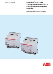
<strong>ABB</strong> i-bus ® <strong>EIB</strong><br />
<strong>Universal</strong> <strong>Interfaces</strong><br />
<strong>US</strong>/U 2.2, GH Q631 0074 R0111<br />
<strong>US</strong>/U <strong>4.2</strong>, GH Q631 0070 R0111<br />
Note:<br />
When connecting to an SO impulse output (e.g. an energy<br />
consumption meter), it must be ensured that it is electrically<br />
isolated from the mains. The correct polarity should also be<br />
observed (“-” on the black core).<br />
5.9 Behaviour during<br />
bus voltage failure<br />
After bus voltage failure, the device switches to energy saving mode for a<br />
short period in order to retain the stored values for as long as possible.<br />
If the bus voltage recovers during energy saving mode, the status of the<br />
device is fully maintained.<br />
After a bus voltage failure of approx. 300 ms (duration is dependent on<br />
the function of the device), the energy saving mode is completed and<br />
the temporary memory is deleted. All the object values are identical to “0”<br />
and the device carries out an initialisation after bus voltage recovery.<br />
5.10 Behaviour after<br />
bus voltage recovery<br />
This section describes the behaviour of the device after bus voltage recovery<br />
with an initialisation.<br />
After bus voltage recovery, there is a transmission delay before telegrams are<br />
sent on the bus. The transmission delay can be set in the general<br />
parameters.<br />
The following diagram indicates the time sequence:<br />
Transmission delay<br />
Initialisation period<br />
ca. 2 s<br />
Bus voltage recovery<br />
Receive and process<br />
telegrams,<br />
scan the inputs<br />
Send telegrams<br />
Diagram 2: Behaviour after bus voltage recovery<br />
On bus voltage recovery, the inputs are scanned after the initialisation period<br />
and the object values are update accordingly, if possible. If the input is operated,<br />
the device behaves as if the operation had started at the end of the<br />
initialisation period.<br />
The behaviour is dependent on the function of the channel. The following list<br />
provides an overview:<br />
47