ABB i-bus® EIB Universal Interfaces US/U 4.2 US/U ... - WindowMaster
ABB i-bus® EIB Universal Interfaces US/U 4.2 US/U ... - WindowMaster
ABB i-bus® EIB Universal Interfaces US/U 4.2 US/U ... - WindowMaster

Create successful ePaper yourself
Turn your PDF publications into a flip-book with our unique Google optimized e-Paper software.
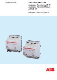
<strong>ABB</strong> i-bus ® <strong>EIB</strong><br />
<strong>Universal</strong> <strong>Interfaces</strong><br />
<strong>US</strong>/U 2.2, GH Q631 0074 R0111<br />
<strong>US</strong>/U <strong>4.2</strong>, GH Q631 0070 R0111<br />
Parameter: “Pulse detection on”<br />
The type of input signal is defined in this parameter. It can be set whether<br />
the contact is a normally open contact or a normally closed contact.<br />
Parameter: “Data width of counter”<br />
The data type of the counter (absolute counter and differential counter)<br />
is defined in this parameter. The data type specifies the counting range for<br />
the counter.<br />
The type of the objects “Telegr. counter value …” and “Differential counter …”<br />
is adapted to the data width.<br />
Parameter: “Counter starts at …”<br />
The starting value of the absolute counter is defined in this parameter.<br />
The starting value is used when there is a counter overflow in order to<br />
calculate the new counter value.<br />
Parameter: “Debounce time / min. operation time”<br />
The debounce prevents unwanted multiple operation of the input e.g. by<br />
bouncing of the contacts. Refer to section 5.1 for the exact function of this<br />
parameter.<br />
Parameter: “Transmit counter values after bus voltage recovery”<br />
If this parameter has the value “yes”, the current value of the counter is sent<br />
on the bus after bus voltage recovery (once the transmission delay has elapsed).<br />
If the differential counter has been enabled, it is also sent on the bus.<br />
After an extended bus voltage failure, the counter is reset to the starting<br />
value. If the differential counter has been enabled, it is reset to zero. If no<br />
data loss has occurred after a short bus voltage failure, the counter contents<br />
are retained.<br />
Parameter: “Enable additional options (…)”<br />
If this parameter is set to “yes”, the parameter window “A-Counter” is displayed.<br />
Additional functions are possible here.<br />
Parameter window: “A-Counter”<br />
Additional functions can be activated in this parameter window for the pulse<br />
counter.<br />
Parameter: “Divider: number of input pulses for one counter step”<br />
It can be set via this parameter how many pulses are necessary to generate<br />
a counting pulse. It thus functions as a divider.<br />
Parameter: “Factor: one counter step changes counter value by”<br />
This parameter defines how much the counter and differential counter should<br />
be increased by in the event of a counting pulse. It thus functions as a factor.<br />
Parameter: “Transmit counter values cyclically”<br />
If this parameter has the value “yes”, the values of the counter and the differential<br />
counter are sent cyclically on the bus.<br />
38