Home Cinema Power Control Software - Panamax!
Home Cinema Power Control Software - Panamax!
Home Cinema Power Control Software - Panamax!

Create successful ePaper yourself
Turn your PDF publications into a flip-book with our unique Google optimized e-Paper software.
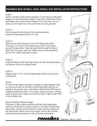
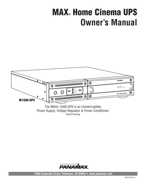
M1500-UPS<br />
MAX® <strong>Home</strong> <strong>Cinema</strong> UPS<br />
POWER<br />
TEST<br />
POWER ON<br />
BATTERY LEVEL LINE FAULT<br />
LOAD LEVEL<br />
UNSAFE VOLTAGE<br />
BATTERY MODE<br />
AVR MODE<br />
Owner’s Manual<br />
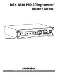
The MAX® 1500-UPS is an Uninterruptible<br />
<strong>Power</strong> Supply, Voltage Regulator & <strong>Power</strong> Conditioner.<br />
Patent Pending<br />
The <strong>Power</strong> Specialists Since 1975<br />
1690 Corporate Circle, Petaluma, CA 94954 • www.panamax.com<br />
®<br />
Pure Sine Wave<br />
Intelligent Critical Load <strong>Control</strong><br />
MAX® <strong>Home</strong> <strong>Cinema</strong> UPS<br />
INS0763 REV. C
Table of Contents<br />
Important Safety Instructions.............................................................pg. 1<br />
Installing Your UPS.............................................................................pg. 2<br />
Basic Operation.............................................................................pgs. 2, 3<br />
Advanced Operation......................................................................pgs. 4, 5<br />
<strong>Home</strong> <strong>Cinema</strong> <strong>Power</strong> <strong>Control</strong> <strong>Software</strong> Installation Instructions...pgs. 5, 6<br />
<strong>Home</strong> <strong>Cinema</strong> <strong>Power</strong> <strong>Control</strong> <strong>Software</strong> Instructions............pgs. 7, 8, 9, 10<br />
Before You Begin<br />
UNPACKING<br />
1. UPS Unit 2. <strong>Power</strong> Cord<br />
3. Phone Cord<br />
5. Rack Mounting Kit<br />
6. <strong>Home</strong> <strong>Cinema</strong><br />
<strong>Power</strong> <strong>Control</strong><br />
<strong>Software</strong><br />
PANAMAX, the <strong>Panamax</strong> logo and MAX are registered US trademarks of <strong>Panamax</strong>.<br />
Protect or Disconnect, and SignalPerfect are trademarks of PANAMAX.<br />
SIDACtor is a registered US trademark of Teccor Electronics, Inc. TiVo is a trademark of TiVo, Inc.<br />
© 2005 PANAMAX CORP. All Rights Reserved.<br />
Battery Features........................................................................pgs. 10, 11<br />
Diagnostics.......................................................................................pg. 11<br />
Troubleshooting................................................................................pg. 12<br />
Technical Specifications....................................................................pg. 12<br />
RS232 Communications Protocol & Command Set.....pgs. 13, 14, 15, 16<br />
FCC Notice and Warranties..............................................................Pg. 17<br />
Inspect the UPS upon receipt. In addition to this manual the box should contain the following:<br />
POWER<br />
TEST<br />
POWER ON<br />
BATTERY LEVEL LINE FAULT<br />
LOAD LEVEL<br />
UNSAFE VOLTAGE<br />
BATTERY MODE<br />
AVR MODE<br />
Pure Sine Wave<br />
Intelligent Critical Load <strong>Control</strong><br />
MAX® <strong>Home</strong> <strong>Cinema</strong> UPS<br />
Please verify that you have received all these items. If not, contact <strong>Panamax</strong>.<br />
4. DB 9 Serial Cable
Important Safety Instructions<br />
This manual contains important instructions that should be followed during installation and maintenance of the UPS and batteries.<br />
Please read and follow all instructions carefully during installation and operation of the unit. Read this manual thoroughly before<br />
attempting to unpack, install, or operate.<br />
CAUTION! The UPS must be connected to an AC power outlet<br />
with fuse or circuit breaker protection.<br />
DO NOT plug the machine into an outlet that is not grounded.<br />
If you need to de-energize this equipment, turn off and unplug<br />
the UPS.<br />
CAUTION! DO NOT USE FOR MEDICAL OR LIFE SUPPORT EQUIP-<br />
MENT! <strong>Panamax</strong> does not sell products for life support or medical<br />
applications. DO NOT use in any circumstance that would<br />
affect operation or safety of any life support equipment, with any<br />
medical applications, or patient care.<br />
CAUTION! The battery can energize hazardous live parts inside<br />
even when the AC input power is disconnected.<br />
CAUTION! To prevent the risk of fire or electric shock install in a<br />
temperature and humidity controlled indoor area, free of conductive<br />
contaminants. (Please see specifications for acceptable<br />
temperature and humidity range).<br />
MODEL # M1500-UPS<br />
POWER<br />
TEST<br />
CAUTION! To reduce the risk of electric shock, do not remove<br />
the cover, except to service the battery. No user serviceable parts<br />
inside, except for the battery.<br />
CAUTION! To avoid electrical shock, turn off the unit and unplug<br />
it from the AC power source before servicing the battery or<br />
installing a component.<br />
CAUTION! DO NOT USE WITH OR NEAR AQUARIUMS! To reduce<br />
the risk of fire, do not use with or near aquariums. Condensation<br />
from the aquarium can come in contact with metal current contacts<br />
and cause the machine to short out.<br />
POWER ON<br />
BATTERY LEVEL LINE FAULT<br />
LOAD LEVEL<br />
USA & Canada (800) 472-5555 • (707) 283-5900 • Fax (707) 283-5901<br />
UNSAFE VOLTAGE<br />
BATTERY MODE<br />
AVR MODE<br />
Pure Sine Wave<br />
Intelligent Critical Load <strong>Control</strong><br />
MAX® <strong>Home</strong> <strong>Cinema</strong> UPS<br />
CAUTION! The 2 silver handles on the battery<br />
access panel are for removing the panel only.<br />
NOT FOR LIFTING PRODUCT.<br />
1
Installing Your UPS<br />
HARDWARE INSTALLATION GUIDE<br />
1. Your new UPS may be used immediately upon receipt.<br />
However, recharging the battery for at least four hours is recommended<br />
to insure that the battery’s maximum charge capacity<br />
is achieved. Charge loss may occur during shipping and storage.<br />
To recharge the battery, simply leave the unit plugged into an AC<br />
outlet. The unit will charge in both the ON as well as the OFF<br />
position. If you wish to use the software, connect the enclosed<br />
serial interface cable to the serial port on the UPS and an open<br />
serial port on the computer.<br />
2. With the UPS unit OFF and unplugged, plug your home theater<br />
equipment into the unit’s rear panel AC outlets. DO NOT plug<br />
a laser printer, copier, space heater, vacuum cleaner, paper shredder<br />
or other large electrical device into the UPS. The power<br />
demands of these devices will overload and possibly damage<br />
the unit.<br />
3. To protect a telephone modem line (DVR or Satellite TV<br />
receiver) or network cable, connect a telephone cable or network<br />
cable from the wall jack outlet to the IN jack of the UPS. Then<br />
connect a telephone cable or network cable from the OUT jack<br />
on the UPS to the equipment’s telephone jack or network device.<br />
Note: This unit provides both telephone and LAN protection on<br />
LAN<br />
TEL<br />
1 2 3 4 5 6 7 8<br />
RJ-45<br />
FRONT PANEL DESCRIPTION<br />
one set of RJ-11/45 jacks. The telephone circuit<br />
uses pins 4 & 5 while the LAN circuit uses<br />
pins 1, 2, 3 & 6. Adapters or custom cables<br />
(not included) must be used when utilizing<br />
both protection circuits at the same time.<br />
Basic Operation<br />
<strong>Power</strong> Switch<br />
Press the power<br />
button to turn the<br />
UPS ON or OFF.<br />
POWER TEST<br />
Test Switch<br />
This UPS performs a self-test automatically when powered on. The test switch allows<br />
you to test the system at any time. When the UPS passes the test, it returns to online<br />
operation. If the UPS fails the self-test, please recharge the battery for 4 hours<br />
and perform another self-test. If it fails after recharging the battery, please replace<br />
the battery. In battery mode, you can press this button to silence an audible alarm.<br />
POWER ON<br />
BATTERY LEVEL LINE FAULT<br />
LOAD LEVEL<br />
UNSAFE VOLTAGE<br />
BATTERY MODE<br />
AVR MODE<br />
4. Plug the UPS into a 2 pole, 3 wire grounded receptacle (wall<br />
outlet). Make sure the wall branch outlet is protected by a fuse or<br />
circuit breaker and does not service equipment with large electrical<br />
demands (e. g. refrigerator, copier, etc.) Avoid using extension<br />
cords. If used, the extension cord must be rated for 15<br />
Amps.<br />
5. Press the power switch to turn the UPS on. The <strong>Power</strong> ON<br />
indicator light will illuminate.<br />
6. The rear panel circuit breakers will open and power to the connected<br />
equipment will be turned OFF if an overload is detected.<br />
To correct this, turn the UPS off, unplug at least one piece of<br />
equipment, wait 10 seconds, check to make sure that the circuit<br />
breakers are reset, and turn the unit on.<br />
7. The UPS will automatically charge the battery whenever it is<br />
plugged into an AC outlet,<br />
8. To maintain optimal battery charge, leave the UPS plugged<br />
into an AC outlet at all times.<br />
9. To store your UPS for an extended period, cover it and store<br />
with the battery fully charged. Recharge the battery every three<br />
months to insure battery life.<br />
Removable Access Panel<br />
Easy to remove for battery access and<br />
replacement.<br />
DO NOT lift product with handles.<br />
They are for panel removal only.<br />
Pure Sine Wave<br />
Intelligent Critical Load <strong>Control</strong><br />
MAX® <strong>Home</strong> <strong>Cinema</strong> UPS<br />
2 USA & Canada (800) 472-5555 • (707) 283-5900 • Fax (707) 283-5901
Basic Operation (continued)<br />
FRONT PANEL DISPLAY LED DESCRIPTIONS<br />
<strong>Power</strong> On Indicator<br />
This LED is illuminated when<br />
the utility condition is normal<br />
and the UPS outlets are providing<br />
clean, protected power.<br />
Battery Level Indicator<br />
This is a visual indication of the<br />
battery charge. If battery capacity<br />
is under 25%, no indicator<br />
LED will illuminate and UPS<br />
starts beeping (if the audible<br />
alarm is enabled).<br />
Battery Mode Indicator<br />
This illuminates during utility failure or<br />
an unsafe voltage condition, indicating<br />
that the battery is supplying power to<br />
the connected equipment.<br />
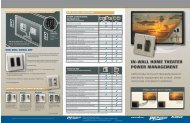
REAR PANEL DESCRIPTION<br />
Non-Critical-Load Outlets<br />
Four battery powered, surge<br />
protected and AVR outlets for<br />
connected equipment insures<br />
temporary uninterrupted operation<br />
of connected equipment<br />
during a power failure.<br />
NON CRITICAL<br />
LOAD OUTLET<br />
BANK<br />
1<br />
Circuit Breakers for<br />
Overload Protection<br />
Resettable circuit<br />
breakers provide<br />
optimal overload<br />
protection.<br />
POWER ON<br />
BATTERY LEVEL LINE FAULT<br />
LOAD LEVEL<br />
Critical Load Outlets<br />
Two battery powered, surge<br />
protected and AVR outlets for<br />
critical-load equipment<br />
insures temporary uninterrupted<br />
operation of connected<br />
equipment during a power<br />
failure.<br />
2<br />
CRITICAL<br />
LOAD<br />
OUTLET<br />
BANK<br />
Line Fault Indicator<br />
This LED will illuminate to warn the user that a<br />
wiring problem such as a bad/missing ground or<br />
reversed wiring exists within the AC receptacle.<br />
If illuminated, disconnect all equipment and contact<br />
an electrician to insure outlet is properly wired.<br />
3<br />
AC INPUT<br />
MAIN<br />
UNSAFE VOLTAGE<br />
BATTERY MODE<br />
AVR MODE<br />
IR1<br />
IR2<br />
RS232 CONTROL<br />
IR OUTPUT PROGRAM / TEST<br />
Unsafe Voltage Indicator<br />
This LED will illuminate to inform the user that<br />
an unsafe line voltage is present and that the<br />
UPS has switched to battery power. This could<br />
be either an over-voltage or under-voltage.<br />
1 2 3 4<br />
AVR Indicator<br />
This indicates that the UPS is operating in automatic voltage regulation mode. When the led is illuminated<br />
continuously, it indicates an input over-voltage and the UPS unit reduces (bucks) the voltage<br />
to the normal operating range. When the led is flashing, it indicates that the input line voltage<br />
is low and that the UPS is increasing (boosts) input voltage to the normal range.<br />
AC <strong>Power</strong><br />
Cord Input<br />
Receptacle<br />
OUTPUT DELAY IR DETECTOR<br />
30 SEC. 5 MIN.<br />
RS232 Serial Communication Port<br />
The serial port allows connection and communication between<br />
the UPS and a HTPC (home theater personal computer) or home<br />
automation system. If used temporarily during setup (with the<br />
included software), it allows the installer to program a number of<br />
variables including the Critical Load Battery Threshold. See the<br />
software documentation for more information.<br />
IN OUT<br />
USA & Canada (800) 472-5555 • (707) 283-5900 • Fax (707) 283-5901<br />
Load Level Indicator<br />
This is a visual indication of the<br />
UPS load.<br />
The 1st arrow will illuminate when<br />
the load is above 25%, the 2nd<br />
above 50% and the 3rd above<br />
75%. The 4th arrow will flash<br />
when the load is between 85%<br />
and 100%.<br />
IR <strong>Control</strong> Section<br />
Learning <strong>Control</strong> Switches – Push to program or test the IR function<br />
IR Detector Window – Receives the IR signal to be learned<br />
Indicator LED’s – Indicates learning status<br />
Output Delay Switches – Set the desired time delay between a power failure and<br />
when the IR signals are sent to the connected equipment<br />
IR Output Jacks – Standard 1/8” (3.5mm) mono jack for connection to an IR<br />
flasher (IR flashers not included)<br />
RJ11/RJ45 Jacks<br />
Ports protect standard<br />
telephone line,<br />
modem, or network<br />
cable.<br />
3
Advanced Operation<br />
Audio/Video components such as Digital Video Recorders, DLP<br />
projectors and any component with volatile memory can benefit<br />
from connection to a UPS. The <strong>Panamax</strong> M1500-UPS takes this<br />
to the next level with a number of features designed specifically<br />
for the home theater.<br />
Critical Load Function<br />
One of the user programmable settings in the <strong>Home</strong> <strong>Cinema</strong><br />
<strong>Power</strong> <strong>Control</strong> software is the Low Battery NCL Shutoff threshold.<br />
This sets the battery capacity level at the point where the<br />
non-critical load outlets are turned off and all remaining battery<br />
power is reserved for equipment plugged into the 2 critical load<br />
outlets. This value is stored internally by the UPS and is not<br />
dependent on having the software running on a computer.<br />
Learning IR <strong>Control</strong><br />
The learning IR function lets you program the UPS to send<br />
standby or shut-down commands to components such as DLP<br />
ceiling projectors. If the power fails, the projector’s lamps are<br />
turned off while the UPS continues providing battery power to<br />
the projector’s cooling fan. Proper shutdown is ensured and<br />
expensive lamps are protected from damage.<br />
Note: This function should only be used with discrete IR codes.<br />
Programming an On/Off toggle command could result in the<br />
equipment being turned ON during a power failure!<br />
IR <strong>Power</strong> Failure Operation<br />
The UPS can learn two IR commands. The learned commands<br />
will be transmitted on both output jacks so you have the ability to<br />
control 2 different pieces of equipment or use a 2-step macro for<br />
one component.<br />
The IR Output Delay switches provide the ability to “ridethrough”<br />
brief power outages without sending a shut-down signal<br />
to the connected device. You have a choice of a 30 second<br />
or 5 minute delay.<br />
1. After a power failure and the selected delay, the IR codes will<br />
be sent to both outputs. The IR LED’s will flash once per second<br />
during the delay time and will stop flashing after the IR code is<br />
output.<br />
2. If the delay settings are the same for both IR1 and IR2, the<br />
IR2 code will be sent to both outputs 2 seconds after IR1.<br />
3. The IR commands will also be transmitted immediately after<br />
the battery charge falls below the critical load battery threshold.<br />
This ensures that equipment will be shutdown properly if the<br />
UPS’s load level is extremely high and the backup time would<br />
be less than the 5 minute ride-through delay.<br />
4. There is no IR output after the power is restored to the<br />
system.<br />
IR LED Color & Status<br />
LED COLOR STATUS<br />
Off Idle<br />
Green, solid Waiting to receive IR signal<br />
Green, flashing IR signal sampled<br />
Red, flashing Failed to learn IR signal<br />
To program IR output:<br />
1. Press and hold the IR1 button for approximately 2 seconds.<br />
2. When the IR1 LED turns solid GREEN, release the button<br />
(after approx. 2 seconds)<br />
3. Point the remote control at the detector window and quickly<br />
press and release the appropriate button on the remote control.<br />
If no signal is received within 10 seconds, the programming<br />
mode is cancelled, the IR1 LED turns off and you will have to<br />
start over.<br />
4. The IR1 LED flashes GREEN if the IR signal is sampled and<br />
stored in memory.<br />
5. The IR1 LED will flash RED if the IR signal was not learned.<br />
Start over at Step 1.<br />
6. Repeat steps 1-5 for IR2.<br />
To clear IR programming:<br />
1. Press and hold the appropriate IR button, release after 2 sec.<br />
2. The IR LED turns solid Green<br />
3. Press the button again. The IR code will be erased from<br />
memory and the LED will turn off.<br />
IR Output Test<br />
1. An IR flasher must be connected to the UPS and in line-ofsight<br />
to the IR receiver window of the equipment to be controlled<br />
in order to verify that the code was learned correctly.<br />
2. Make sure that the component to be controlled is turned ON.<br />
3. Press and release the IRx button. The code for IRx will be<br />
transmitted on both IR1 and IR2 outputs.<br />
4. If you are testing a 2-step macro, be sure to press the second<br />
IR button to transmit that code.<br />
4 USA & Canada (800) 472-5555 • (707) 283-5900 • Fax (707) 283-5901
Advanced Operation (continued)<br />
5. If the learning process was successful, the controlled equipment<br />
should accept the IR command and turn off or go into<br />
standby mode.<br />
6. Reprogram the IR command if the controlled equipment does<br />
not respond.<br />
a. Be sure that the batteries in the “teaching remote” are fresh<br />
and do not need to be replaced.<br />
b. If “press & release” (Step 3 in Programming) doesn’t work,<br />
try “press & hold” on the remote control button being taught to<br />
the UPS.<br />
RS232 <strong>Control</strong> with Open Protocol<br />
The RS232 serial interface can be used in the following ways:<br />
1. Initial system setup. An installer can use a notebook computer<br />
to set the variables within the <strong>Home</strong> <strong>Cinema</strong> <strong>Power</strong> <strong>Control</strong><br />
<strong>Home</strong> <strong>Cinema</strong> <strong>Power</strong> <strong>Control</strong> <strong>Software</strong><br />
The M1500-UPS has one rear-panel serial port that provides the<br />
ability to program special functions, safely shutdown a home theater<br />
PC (HTPC) or integrate the UPS with home automation systems.<br />
Use of the <strong>Panamax</strong> software is optional. The communications<br />
protocol is “open”; a programmer can write their own control<br />
program or integrate the UPS’s programming/control functions<br />
into home automation software if desired. The UPS will provide<br />
surge suppression, automatic voltage regulation and battery<br />
backup without the software. Automatic shutdown of an<br />
HTPC requires the use of the software.<br />
<strong>Software</strong> Installation<br />
For Windows XP (<strong>Home</strong> and Professional)<br />
1. Click on Start and then click on <strong>Control</strong> Panel.<br />
2. Double-click on <strong>Power</strong> Options then click on the UPS tab.<br />
3. Set the manufacturer to none.<br />
4. Exit to the desktop and shutdown your computer.<br />
5. Turn the UPS off and unplug it.<br />
6. Connect the serial interface cable to the UPS and an open<br />
serial port on the back of the computer. (Note: You must use<br />
the serial cable that was supplied with the unit).<br />
software. Once the setup is completed, the notebook computer<br />
can be disconnected. All settings are stored in the UPS.<br />
2. Connection to a <strong>Home</strong> Theater Personal Computer (HTPC).<br />
Functionality is very similar to a standard UPS with a PC.<br />
The UPS can provide continued power to the HTPC to maintain<br />
recording capabilities if it is being used as a digital video<br />
recorder. It is also capable of saving open documents and<br />
shutting down the HTPC during extended power failures.<br />
This requires a permanent RS232 connection to the HTPC<br />
and having the <strong>Home</strong> <strong>Cinema</strong> <strong>Power</strong> <strong>Control</strong> software running<br />
in the background on the HTPC.<br />
3. Integration with home automation systems like AMX and<br />
Crestron. The serial communications command set and protocol<br />
is open and is published later in this manual. This information<br />
can be used by the automation system programmer for both UPS<br />
control by the automation system and reporting of power events<br />
by the UPS to the automation system.<br />
7. Plug the UPS into an AC outlet, turn the UPS on and start your<br />
computer.<br />
8. Windows will recognize your UPS as “New Hardware”.<br />
9. Insert the software disk into the computer’s drive. The installation<br />
program should start automatically. If the installation<br />
program does not start automatically, open it manually with<br />
the Window’s “Run” command.<br />
10. Follow the on-screen instructions.<br />
11. Once the software has finished installing, remove the disk<br />
and restart your computer.<br />
For Windows 95/98/Me<br />
1. Turn off your UPS.<br />
2. Connect the Serial Cable to your UPS and the open serial port<br />
on the rear panel of the computer. (Note: You must use the serial<br />
cable that was supplied with the unit).<br />
3. Plug the UPS into an AC outlet, turn the UPS on and then start<br />
your computer.<br />
4. Follow the instructions below for your PC’s operating system.<br />
USA & Canada (800) 472-5555 • (707) 283-5900 • Fax (707) 283-5901<br />
5
<strong>Home</strong> <strong>Cinema</strong> <strong>Power</strong> <strong>Control</strong> <strong>Software</strong> (continued)<br />
5. Windows will recognize your UPS as “New Hardware”.<br />
6. Insert the software disk into the computer’s drive. The installation<br />
program should start automatically. If the installation program<br />
does not start automatically, open it manually with the<br />
Window’s “Run” command.<br />
7. Follow the on-screen instructions.<br />
8. Once the software is installed, remove the disk and restart<br />
your computer.<br />
For Windows 2000<br />
1. Click on Start, point to Settings then click <strong>Control</strong> Panel.<br />
2. Double-click on <strong>Power</strong> Options.<br />
3. On the UPS Tab, click Select.<br />
4. In the UPS Selection Dialog Box, under Manufacturers,<br />
click None.<br />
5. Exit to the desktop.<br />
6. Shutdown the computer.<br />
7. Turn the UPS off and unplug it.<br />
8. Connect the serial interface cable to the UPS and an open<br />
serial port on the back of the computer. (Note: You must use<br />
the serial cable that was supplied with the unit).<br />
9. Plug the UPS into an AC outlet, turn the UPS on and start<br />
your computer.<br />
10. Windows will recognize your UPS as “New Hardware”.<br />
11. Insert the software disk into the computer’s drive. The<br />
installation program should start automatically. If the installation<br />
program does not start automatically, open it manually with the<br />
Window’s “Run” command.<br />
12. Follow the on-screen instructions.<br />
13. Once the software has finished installing, remove the disk<br />
and restart your computer.<br />
For Windows NT 4.0<br />
1. Click on Start, point to Settings then click <strong>Control</strong> Panel.<br />
2. Double-click on the UPS Icon.<br />
3.. Remove the check mark from the box labeled UPS is installed<br />
on.<br />
4. Click OK.<br />
5. Acknowledge the message that the UPS is in an unknown<br />
state.<br />
6. Exit to the desktop.<br />
7. Shutdown your computer.<br />
8. Turn the UPS off and unplug it.<br />
9. Connect the serial interface cable to the UPS and an open serial<br />
port on the back of the computer. (Note: You must use the<br />
serial cable that was supplied with the unit).<br />
10. Plug the UPS into an AC outlet, turn the UPS on and then<br />
start your computer.<br />
11. Click on Start, point to Settings then click <strong>Control</strong> Panel.<br />
12. Double-click on Add/Remove Programs.<br />
13. Insert the software disk into the computer’s drive. The<br />
installation program should start automatically. If the installation<br />
program does not start automatically, open it manually with the<br />
Window’s “Run” command.<br />
14. Click Install.<br />
15. Follow the on-screen instructions.<br />
16. Once the software is installed, remove the disk and restart<br />
your computer.<br />
When your computer restarts, the <strong>Home</strong> <strong>Cinema</strong> <strong>Power</strong> <strong>Control</strong><br />
software will appear on your screen for a few seconds, and then<br />
minimize. It will appear as a blue and white battery icon located<br />
in the system tray, near the clock.<br />
6 USA & Canada (800) 472-5555 • (707) 283-5900 • Fax (707) 283-5901
<strong>Home</strong> <strong>Cinema</strong> <strong>Power</strong> <strong>Control</strong> <strong>Software</strong> Instructions<br />
Overview<br />
<strong>Panamax</strong>’s <strong>Home</strong> <strong>Cinema</strong> <strong>Power</strong> <strong>Control</strong> software is designed for<br />
use with Windows 95, Windows 98, Windows Me, Windows NT,<br />
Windows 2000 and Windows XP. It works in conjunction with<br />
the UPS to provide full protection of home theater equipment<br />
including digital video recorders, home theater PC’s (HTPC)<br />
and video projectors/lamps.<br />
This program may be used temporarily during the Initial system<br />
setup. An installer can use a notebook computer to set the variables<br />
within the <strong>Home</strong> <strong>Cinema</strong> <strong>Power</strong> <strong>Control</strong> software. Once the<br />
setup is completed, the notebook computer can be disconnected.<br />
All settings are stored in the UPS.<br />
The software can also be used to manage a <strong>Home</strong> Theater<br />
Personal Computer (HTPC). Functionality is very similar to a<br />
standard UPS with a PC. The UPS can provide continued power<br />
to the HTPC to maintain recording capabilities if it is being used<br />
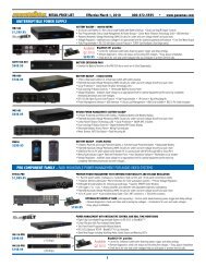
MAIN MENU<br />
2. <strong>Power</strong> Button:<br />
Closes the program window.<br />
3. Minimize Button:<br />
Minimize the program window.<br />
4. Setup Button:<br />
Opens the Setup Window.<br />
1. Log Button: Opens the Event Log Window.<br />
5. Model: Shows the model<br />
of UPS that is being used.<br />
6. Schedule Button:<br />
Click this button to access the<br />
Schedule Window.<br />
as a digital video recorder. It is also capable of saving open documents<br />
and shutting down the HTPC during extended power failures.<br />
This requires a permanent RS232 connection to the HTPC<br />
and having the <strong>Home</strong> <strong>Cinema</strong> <strong>Power</strong> <strong>Control</strong> software running in<br />
the background on the HTPC. When a power failure occurs,<br />
open files are saved under auto-assigned file names or existing<br />
file names and the files closed. The computer and UPS are<br />
automatically shutdown to conserve battery power. Files with<br />
auto-assigned names will be saved under C:\PCTemp, where C<br />
is the name of your main hard drive. Files that have previously<br />
been saved will be saved in their original location.<br />
There is also a Schedule feature that can automatically save and<br />
close open files and then shutdown the computer and UPS at a<br />
user specified date and time as well as re-start the computer at<br />
a user specified date and time. Use of this feature is optional<br />
and is not required for the power failure shutdown to occur.<br />
7. Status Bar: Displays messages<br />
about the status of the software.<br />
USA & Canada (800) 472-5555 • (707) 283-5900 • Fax (707) 283-5901<br />
7
<strong>Home</strong> <strong>Cinema</strong> <strong>Power</strong> <strong>Control</strong> <strong>Software</strong> Instructions (continued)<br />
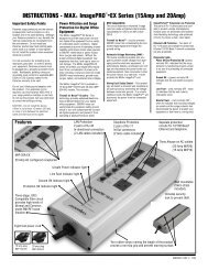
MAIN WINDOW DESCRIPTIONS<br />
1. Battery Level: Displays the<br />
current charge on the battery. The<br />
indicator will display a red color<br />
when a power failure occurs.<br />
10. Frequency:<br />
This indicator displays<br />
the frequency of the<br />
utility power.<br />
9. Scheduled On:<br />
The <strong>Home</strong> <strong>Cinema</strong> <strong>Power</strong><br />
<strong>Control</strong> software can be<br />
scheduled to turn your<br />
connected equipment on.<br />
It can only be set when a<br />
Scheduled Off is also set.<br />
Scheduled On settings<br />
that are set to occur within<br />
seven days will be displayed.<br />
SETUP MENU<br />
2. Input Voltage: Shows the current input<br />
voltage. The input normally appears in green, but<br />
will turn red if the input voltage is lower than 85v<br />
or higher than 150v.<br />
8. Countdown: For use with a <strong>Home</strong> Theater PC. When the program<br />
detects that the utility voltage is below 88 volts or above 147 volts, the<br />
countdown will begin. When the countdown reaches zero, the program will<br />
save and close any open applications, and then shut down the operating<br />
system in an intelligent and orderly manner.<br />
12. Time between<br />
power failure and<br />
shutdown: For use with<br />
an HTPC. This is the user<br />
controllable delay between<br />
when the power fails and<br />
the software starts the<br />
shutdown process. If<br />
unchecked, the unit will<br />
run on battery until the low<br />
battery signal is received<br />
(2 minutes of backup time<br />
remaining) and then start<br />
the shutdown process.<br />
11. Time between<br />
power failure and<br />
initial warning:<br />
Sets the time delay<br />
between a power failure<br />
and the first audible<br />
alarm.<br />
1. Play voice: Enables audible<br />
voice messages through your<br />
computer speakers. A sound<br />
card and speakers are required.<br />
10. Delay between warning messages:<br />
Sets the delay between the audible alarms (during a<br />
power failure).<br />
7. Approximate Backup Time: Indicates the approximate<br />
amount of backup time that is available, based upon the battery<br />
capacity and the load on the system. This indicator can appear in red,<br />
yellow, or green, depending upon the number of minutes available.<br />
2. Alarm On: Toggles<br />
the audible alarm on and off.<br />
9. UPS Self-Test: Allows the user to test the<br />
UPS without having to unplug the unit from the wall.<br />
When Run is clicked, the UPS will switch to battery<br />
power and the unit will beep.<br />
3. Output Voltage: Shows the<br />
output voltage of the UPS.<br />
4. Load Level: Shows the % of capacity<br />
that is currently being used. If the load level<br />
exceeds 90%, the indicator will change to a<br />
red color.<br />
8 USA & Canada (800) 472-5555 • (707) 283-5900 • Fax (707) 283-5901<br />
6. Scheduled Off:<br />
The program can be set<br />
to automatically shutdown<br />
the system at a user<br />
specified time. Scheduled<br />
Off settings that are set to<br />
occur within seven days<br />
will be displayed. When<br />
combined with the<br />
Scheduled On function,<br />
connected equipment can<br />
automatically be rebooted.<br />
3. UPS Communication Media: Leave this on “Auto” for automatic<br />
detection or select the correct communications port from the dropdown<br />
list. The port assigned to the UPS needs to be used exclusively for<br />
the UPS software.<br />
8. About: This button will display<br />
information about the software,<br />
as well as contact information.<br />
5. Temperature:<br />
Displays the internal operating<br />
temperature of the<br />
unit. If the temperature<br />
exceeds 158°F (70°C), the<br />
indicator will change from<br />
green to red.<br />
4. OK: Closes the<br />
window and saves<br />
changes.<br />
5. Cancel: Closes<br />
the window without<br />
saving changes.<br />
6. Default:<br />
Returns the software<br />
to original factory<br />
settings.<br />
7. Advanced:<br />
Opens the Advanced<br />
Setup Window.
<strong>Home</strong> <strong>Cinema</strong> <strong>Power</strong> <strong>Control</strong> <strong>Software</strong> Instructions (continued)<br />
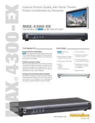
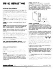
ADVANCED SETUP MENU<br />
1. Low Battery HTPC Shutoff: For use with a <strong>Home</strong> Theater PC.<br />
Sets the low battery cutoff level. The user can slightly extend the UPS run<br />
time by adjusting this setting. This setting must be higher than the Critical<br />
Load Threshold if the HTPC is plugged into a non-critical load outlet.<br />
9. High-Voltage<br />
Failure: Sets the<br />
upper level where the<br />
UPS will cycle to battery.<br />
This level can be adjusted<br />
from 137V to 147V.<br />
8. Low-Voltage<br />
Failure: Sets the lower<br />
level where the UPS will<br />
cycle to battery. This level<br />
can be adjusted from 88V<br />
to 97V.<br />
7. Battery-mode<br />
Output Voltage:<br />
Sets the voltage that the<br />
unit will output. This<br />
level can be adjusted<br />
from 110V to 130V when<br />
running on battery.<br />
SCHEDULE MENU - SPECIAL<br />
1. Special<br />
Setting: Allows<br />
you to schedule a<br />
one-time shutdown/startup.<br />
9. Turn On: Select<br />
the day/date and time<br />
that you want the computer<br />
system to restart.<br />
Can only be used in<br />
conjunction with a<br />
scheduled shutdown.<br />
8. Schedule<br />
Display: Window<br />
display of the<br />
days/dates and times<br />
of any scheduled<br />
startups and shutdowns.<br />
2. Weekly Setting: Allows you to<br />
schedule a shutdown and start up based<br />
upon the day of the week.<br />
2. Low Battery NCL Shutoff: NCL stands for Non-<br />
Critical Load. Sets the % of battery capacity at which all<br />
remaining battery power is reserved for the equipment<br />
plugged into the critical load outlet bank. <strong>Power</strong> to the 4<br />
NCL outlets will be turned off at this point.<br />
3. Turn Off: Select the day/date and time that<br />
you want the computer system to shutdown. This is<br />
optional and has no effect on whether your computer<br />
will shut down during a power failure.<br />
USA & Canada (800) 472-5555 • (707) 283-5900 • Fax (707) 283-5901<br />
3. Cold Start: When this is<br />
enabled, the UPS can start in the<br />
absence of AC power. To maximize<br />
battery life, it is recommended to<br />
keep this disabled.<br />
4. OK: Closes<br />
the windows and<br />
saves changes.<br />
5. Cancel: Closes<br />
the window without<br />
saving changes.<br />
6. Default:<br />
Restores the settings<br />
to the factory defaults.<br />
4. OK: Closes the window.<br />
Please note: You<br />
must click Add to add<br />
the item to the schedule.<br />
5. Cancel: Closes<br />
the window without<br />
saving any schedules<br />
even if one was added<br />
to the Schedule Display<br />
Window. Does not cancel<br />
previously applied<br />
schedules.<br />
6. Add: Adds an<br />
item to the schedule.<br />
7. Delete: Clears<br />
the selected item<br />
from the schedule.<br />
9
<strong>Home</strong> <strong>Cinema</strong> <strong>Power</strong> <strong>Control</strong> <strong>Software</strong> Instructions (continued)<br />
LOG MENU<br />
1. Log Display:<br />
This window displays<br />
the information as<br />
selected by the Event,<br />
Closed Application<br />
Information, or Data<br />
2. Event: When this option is<br />
selected, the log will display a list<br />
of events such as power failure,<br />
program start, and program end.<br />
3. Closed Application<br />
Information: When this option<br />
is selected, the log will display the<br />
names and location of any files that<br />
were auto-saved by the software.<br />
4. Data Record: When this<br />
option is selected, the log will display<br />
a record of the items that are<br />
shown in the main window.<br />
5. OK: Closes the<br />
window and saves<br />
any changes.<br />
Record option buttons. 6. Cancel: Closes<br />
the window without<br />
saving any changes.<br />
Battery Features<br />
Testing The Battery Backup Function<br />
Once you have set up your UPS system, you may wish to test it.<br />
Make sure that the UPS has been charged for at least 4 hours<br />
before testing.<br />
To test the UPS, simply depress the test button located on the<br />
front of the unit. The unit will cycle to battery and emit an audible<br />
beep. The unit will stop beeping when the test is complete.<br />
You may also use the self-test function in the software. To use<br />
the software self-test, open the main window, and then click<br />
mode on Setup. Click the red run button. The unit will cycle to<br />
battery mode and emit an audible beep. With the software selftest,<br />
the unit will switch back to AC power automatically.<br />
Battery Replacement<br />
Read and follow the IMPORTANT SAFETY INSTRUCTIONS before<br />
servicing the battery.<br />
Service the battery under the supervision of personnel knowledgeable<br />
of batteries and their precautions. Servicing the battery<br />
can only be performed by qualified personnel.<br />
CAUTION! Use only the specified type of battery. See your dealer<br />
for replacement batteries.<br />
10 USA & Canada (800) 472-5555 • (707) 283-5900 • Fax (707) 283-5901<br />
7. Clear: Clears the<br />
selected log.<br />
CAUTION! The battery may present the risk of electrical shock.<br />
Do not dispose of batteries in a fire as they may explode. Follow<br />
all local ordinances regarding proper disposal of batteries.<br />
CAUTION! Do not open or mutilate the batteries. Released electrolyte<br />
is harmful to the skin and eyes and may be toxic<br />
CAUTION! A battery can present a high risk of short circuit current<br />
and electrical shock. Take the following precautions before<br />
replacing the battery:<br />
1. Remove all watches, rings or other metal objects.<br />
2. Only use tools with insulated handles.<br />
3. Do not lay tools or metal parts on top of battery or any<br />
terminals.<br />
4. Wear rubber gloves and boots.<br />
5. Determine if the battery is inadvertently grounded. If inadvertently<br />
grounded, remove source of ground. CONTACT WITH A<br />
GROUNDED BATTERY CAN RESULT IN ELECTRICAL SHOCK! The<br />
likelihood of such shock will be reduced if such grounds are<br />
removed during installation and maintenance (applicable to a<br />
UPS and a remote battery supply not having a grounded circuit).
Battery Features (continued)<br />
Battery Replacement Procedure<br />
POWER ON<br />
BATTERY LEVEL LINE FAULT<br />
LOAD LEVEL<br />
UNSAFE VOLTAGE<br />
BATTERY MODE<br />
AVR MODE<br />
Diagnostics<br />
Pure Sine Wave<br />
Intelligent Critical Load <strong>Control</strong><br />
MAX® <strong>Home</strong> <strong>Cinema</strong> UPS<br />
1. Remove the right side front panel using<br />
pull-out handles.<br />
4. Remove the four retaining screws.<br />
<strong>Power</strong><br />
On LED<br />
On<br />
On<br />
On<br />
On<br />
Off<br />
Off<br />
On/Off<br />
Off<br />
On<br />
Off<br />
On/Off<br />
Wiring<br />
Fault LED<br />
Off<br />
Off<br />
Off<br />
Off<br />
Off<br />
Off<br />
Off<br />
Off<br />
Off<br />
Off<br />
On<br />
AVR LED<br />
Off<br />
Slow Flash<br />
Rapid Flash<br />
On<br />
Off<br />
Off<br />
On/Off/Flash<br />
Off<br />
On/Off/Flash<br />
Off<br />
On/Off/Flash<br />
Using<br />
Battery LED<br />
Off<br />
Off<br />
Off<br />
Off<br />
On<br />
On<br />
On/Off<br />
On<br />
Off<br />
Off<br />
On/Off<br />
2. Remove the two retaining screws of the<br />
cable protection cover then remove the cover.<br />
Battery pullout tab handle<br />
5. Pull the battery pack out from the unit.<br />
Circuit<br />
Breaker<br />
Set<br />
Set<br />
Set<br />
Set<br />
Set<br />
Set<br />
Set<br />
Up<br />
Set<br />
Set<br />
Set/Up<br />
Audible<br />
Alarm<br />
Off<br />
Off<br />
Off<br />
Off<br />
Two Beeps<br />
Rapid Beeps<br />
Long Beep<br />
Long Beep<br />
None<br />
Off<br />
None<br />
Condition<br />
Normal<br />
USA & Canada (800) 472-5555 • (707) 283-5900 • Fax (707) 283-5901<br />
3. Disconnect the black and red cable.<br />
6. Slide a new battery pack into the unit.<br />
Assemble the screws, cover, cable and front<br />
panel in the reverse sequence of above steps.<br />
7. Recharge the unit for 4-8 hours to ensure<br />
the UPS performs expected runtime.<br />
AVR- Max. boost 13% of input voltage for output regulation while input voltage is<br />
from 8% to 15% under nominal.<br />
AVR- Max. boost 26% of input voltage for output regulation while input voltage is<br />
from 15% to 26% under nominal.<br />
AVR- Max. buck 15% of input voltage for output regulation while input voltage is<br />
from 8% to 26% over nominal.<br />
Utility Failure- The UPS is providing battery power to the connected equipment.<br />
Utility Failure- The UPS is providing battery power. Rapid beeps indicate the battery<br />
will run out of charge within a few minutes.<br />
Overload- Turn the UPS off and unplug at least one piece of equipment from the UPS.<br />
Wait 5 seconds, reset the circuit breaker and restart the UPS.<br />
Overload- Turn the UPS off and unplug at least one piece of equipment from the UPS.<br />
Wait 5 seconds, reset the circuit breaker and restart the UPS.<br />
Weak Battery- Recharge the battery for at least 8 hours. If Check Battery is illuminated,<br />
contact <strong>Panamax</strong> for battery replacement information.<br />
Surge Protection Malfunction- <strong>Power</strong> surge has damaged the unit. Please contact<br />
<strong>Panamax</strong>.<br />
Electrical Wiring Fault- Indicates wiring problems such as a bad ground, missed<br />
ground or reversed wiring within the AC outlet. User is advised to disconnect all<br />
electrical equipment from the outlet and have the outlet checked by an electrician.<br />
11
Troubleshooting<br />
Problem<br />
Outlets do not provide power to<br />
equipment.<br />
The UPS does not perform<br />
expected runtime.<br />
The UPS will not turn on.<br />
<strong>Software</strong> is inactive.<br />
Possible Cause<br />
Circuit breaker is tripped due to overload<br />
Batteries are discharged.<br />
Unit has been damaged by a surge or spike.<br />
Battery is not fully charged.<br />
Battery is slightly worn out.<br />
The on/off switch is designed to prevent damage by rapidly<br />
turning it off and on.<br />
The unit is not connected to an AC outlet.<br />
The battery is worn out.<br />
Mechanical problem.<br />
The serial cable is not connected.<br />
The serial cable is connected to the wrong port.<br />
The unit is not providing battery power<br />
The serial cable is not the cable that was provided with the unit.<br />
Technical Specifications<br />
AC SPECIFICATIONS<br />
CAPACITY<br />
(VA)__________________________________________________________1500VA<br />
(Watts)________________________________________________________1000W<br />
INPUT<br />
Voltage Range____________________________________________88Vac - 147Vac<br />
Frequency Range______________________________________________47 - 63 Hz<br />
OUTPUT<br />
On Battery Output Voltage_____________________Pure Sine Wave at 120VAC +/- 5%<br />
On Battery Output Frequency__________________________________ 60 Hz +/- 1%<br />
Transfer Time_____________________________________________________ 4ms<br />
PROTECTION & FILTRATION<br />
On Utility____________________________________ Over/Under voltage protection<br />
On Battery________________________________________ Internal Current Limiting<br />
Patented <strong>Power</strong> Management Circuit____________________________________Yes<br />
Overvoltage Shutoff ____________________________________________144V ±8V<br />
Undervoltage Shutoff ___________________________________________ 90V ±6V<br />
Thermal Fusing____________________________________________________Yes<br />
Initial Clamping Level ________________________________ 200V Peak, 141V RMS<br />
UL 1449 Suppression Rating ________________________________________330V<br />
Protection Modes __________________________________________L-N, L-G, N-G<br />
Response Time ___________________________________________________ < 1 n<br />
Single Pulse Energy Dissipation_________________________________1650 Joules<br />
Peak Impulse Current ___________________________________________ 52,000 A<br />
EMI/RFI Noise Filtration______________________________50dB (100kHz – 1 MHz)<br />
TELCO PROTECTION<br />
Fuseless/Auto-Resettable_____________________________________________Yes<br />
Clamping Level___________________________________________________ 260V<br />
Capacitance _____________________________________________ 30 pf (approx.)<br />
Suppression Modes_________________________________ Metallic & Longitudinal<br />
Wires Protected_______________________________________2 wire, 1 pair (4 & 5)<br />
Connectors______________________________________RJ-11/45 Shared with LAN<br />
Solution<br />
Turn the UPS off and unplug at least one piece of equipment.<br />
Wait 10 seconds, reset the circuit breaker and then turn the UPS on.<br />
Recharge the unit for at least 4 hours.<br />
Recharge the battery by leaving the UPS plugged in.<br />
Recharge the battery by leaving the UPS plugged in.<br />
Contact <strong>Panamax</strong> about replacement batteries.<br />
Turn the UPS off. Wait 10 seconds and then turn the UPS on.<br />
The unit must be connected to a 110/120v 60Hz outlet.<br />
Contact <strong>Panamax</strong> about replacement batteries.<br />
Contact <strong>Panamax</strong>.<br />
Connect the serial cable to the UPS unit and an open serial port of<br />
your computer. You must use the cable included with the unit.<br />
Try another serial port on your computer.<br />
Shutdown your computer and turn the UPS off. Wait 10 seconds and<br />
turn the UPS on. This should reset the unit.<br />
You must use the cable included with the unit for the software.<br />
LAN PROTECTION<br />
Compatibility___________________________________________________________10/100bT<br />
Clamping Level_______________________________________________________________7V<br />
Suppression Modes_____________________________________Differential & Common Ground<br />
Wires Protected____________________________________________________Pins 1, 2, 3, & 6<br />
Connectors______________________________________________RJ/11-45 Shared with Telco<br />
BATTERY<br />
Sealed____________________________________________________________________Yes<br />
Maintenance-free____________________________________________________________Yes<br />
Lead acid___________________________________________________________________Yes<br />
User replaceable_____________________________________________________________Yes<br />
Typical recharge time _______________________________________________________8 hrs.<br />
COMMUNICATION<br />
<strong>Software</strong> ___________________________________ Included (Windows95/98/ME/NT/2000/XP)<br />
Hardware_______________________________________________ RS232 (open command set)<br />
Programmable IR_________________(learning) sends IR signals to equipment after power failure<br />
PHYSICAL<br />
Rack Mountable_________________________________________Yes (rack mount kit included)<br />
Maximum Dimensions_____________________________________________17" x 3.5 x 15.3"<br />
Weight (lbs.)________________________________________________________________ 59<br />
Outlets______________________________________________ 6 Total (2 assigned critical load)<br />
GENERAL<br />
Lightning protection__________________________________________________________Yes<br />
Product Warranty_________________________________________________________ 3 Years<br />
Design and specifications subject to change without notice due to product improvement.<br />
12 USA & Canada (800) 472-5555 • (707) 283-5900 • Fax (707) 283-5901
RS232 Communications Protocol & Command Set<br />
Communications Protocol<br />
Baud rate:_______2400 bps<br />
Start bit: ____________1 bit<br />
Data length:_________8 bits<br />
<strong>Control</strong>ler Commands<br />
Commands and responses are in the form of ASCII character strings terminated with a carriage<br />
return ASCII character 13 (hex).<br />
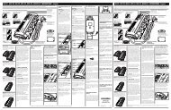
It is important to understand how the UPS circuitry switches power to the outlets in order to use<br />
the outlet switching commands effectively. The following diagram provides a basic illustration:<br />
AC INPUT/BATTERY<br />
MAIN<br />
The UPS provides one bank of switched outlets (Outlet Bank 1) that can be controlled independently.<br />
These are referred to as Non-Critical Load (NCL) Outlets.<br />
The other outlet bank (Outlet Bank 2) will be referred to as Critical Load (CL) Outlets.<br />
Note that NCL outlets cannot be energized unless the critical load outlets are on.<br />
NCL outlets are designated for equipment that is considered non-critical.<br />
<strong>Power</strong> will be turned off if the battery charge falls below a set threshold (refer 2.5).<br />
It is desirable to have the ability to switch the power to the outlets on and off to force a “hard” reboot of equipment.<br />
Devices such as satellite receivers often “crash” and must be reset.<br />
The following are commands made by the controller to the UPS:<br />
Main <strong>Power</strong> On<br />
Figure 2.1 UPS <strong>Power</strong> Switching<br />
Send to UPS: MAIN_ON<br />
Stop bit:_______________1 bit<br />
Parity:________________None<br />
Flow control:____________one<br />
If power is not switched off due to low battery conditions:<br />
Action: AC power is switched ON to the CL out<br />
lets by closing the AC input relay or turn<br />
ing on the inverter.<br />
Response from UPS: CL_OUTLETS_ON<br />
NCL_OUTLETS_ON (if NCL relay is<br />
closed)<br />
If power is already switched off due to low battery conditions:<br />
Action: None<br />
Response from UPS: LOWBATT<br />
USA & Canada (800) 472-5555 • (707) 283-5900 • Fax (707) 283-5901<br />
NCL<br />
Main <strong>Power</strong> Off<br />
To Non-Critical Load (NCL) Outlets<br />
To Critical Load (CL) Outlets<br />
Send to UPS: MAIN_OFF<br />
DB9 Pinout Diagram<br />
5 4 3 2 1<br />
6 7 8 9<br />
PIN NO.<br />
1<br />
2<br />
3<br />
4<br />
5<br />
6<br />
7<br />
8<br />
9<br />
Action: All outlets are de-energized by disconnecting<br />
the AC input relay and turning<br />
off the Inverter.<br />
Response from UPS: NCL_OUTLETS_OFF<br />
CL_OUTLETS_OFF<br />
SIGNAL<br />
-<br />
TRANSMIT<br />
RECEIVE<br />
DTR<br />
SIGNAL GROUND<br />
-<br />
RTS<br />
-<br />
-<br />
DTR - Data Terminal Ready<br />
RTS - Request To Send<br />
13
RS232 Communications Protocol & Command Set (continued)<br />
Non Critical Load Outlets On<br />
This command controls the relay that feeds power to the NCL Outlets.<br />
Note that if the MAIN relay is off, the outlets will still be un-energized.<br />
Send to UPS: NCL_ON<br />
Action: NCL relay closes.<br />
Response from UPS: NCL_OUTLETS_ON (if MAIN<br />
relay is ON)<br />
Non Critical Outlets Off<br />
Send to UPS: NCL_OFF<br />
Action: NCL relay opens.<br />
NCL_OUTLETS_OFF (if MAIN<br />
relay is OFF)<br />
Response from UPS: NCL_OUTLETS_OFF<br />
Set Low Battery NCL (Non-Critical Load) Shutoff<br />
It is desirable to allow the user to set the battery storage threshold in<br />
which the non-critical load outlets will shut off therefore reserving the<br />
remaining battery charge for the critical equipment. If the battery<br />
charge falls below the threshold, Non Critical Load Outlets are turned<br />
OFF.<br />
A common example of critical equipment would be a projector. It is<br />
critical that power be maintained to a projector to allow its fan to run<br />
and cool the bulb. If the bulb is allowed to overheat, it will be damaged<br />
and is very expensive to replace.<br />
Send to UPS: BATTHRESHXX<br />
represents a space: 20 Hex<br />
XX is a number between 25 and 60<br />
represented in ASCII.<br />
If XX is a valid number, between 25 and 60:<br />
Action: Assigns the battery threshold variable<br />
with the value XX<br />
Response from UPS: BTHRESHXX<br />
If XX is not valid:<br />
Action: None<br />
Response from UPS: INVALIDCMD<br />
Enable Audible Alarm<br />
It is important that the UPS be as quiet as possible as it will be located<br />
in a home theater environment. It is desirable to control the warning<br />
beeper. The default setting for the alarm is OFF.<br />
Send to UPS: BEEPON<br />
Action: The beeper will sound when running<br />
from battery.<br />
Response from UPS: BEEPISON<br />
Disable Warning Beeper<br />
Send to UPS: BEEPOFF<br />
Action: The beeper will not sound when running<br />
from battery.<br />
Response from UPS: BEEPISOFF<br />
Restore Default Settings<br />
Send to UPS: RESTORE<br />
Action: Set Non-critical load threshold (2.5)<br />
to 66%<br />
Disable the warning beeper (2.7)<br />
Set High Voltage Failure Threshold to<br />
147V (2.8)<br />
Set Low Voltage Failure Threshold to<br />
88V (2.9)<br />
Set Battery Mode Voltage to 120V (2.10)<br />
Response from UPS: DEFAULTSRESTORED<br />
QUERIES<br />
Request Outlet Status<br />
Transmit the ON/OFF status of the outlet banks.<br />
Send to UPS: ?OUTLETSTAT<br />
If NCL Outlets are ON:<br />
Response from UPS: NCL_OUTLETS_ON<br />
If NCL Outlets are OFF:<br />
Response from UPS: NCL_OUTLETS_OFF<br />
If CL Outlets are ON:<br />
Response from UPS: CL_OUTLETS_ON<br />
If CL Outlets are OFF:<br />
Response from UPS: CL_OUTLETS_OFF<br />
14 USA & Canada (800) 472-5555 • (707) 283-5900 • Fax (707) 283-5901
RS232 Communications Protocol & Command Set (continued)<br />
Request Input Voltage Level<br />
Transmit the input AC voltage status<br />
Send to UPS: ?INPUTVOLTS<br />
Response from UPS: XXXVACIN<br />
Request Output Voltage Status<br />
Transmit the output voltage state<br />
Send to UPS: ?OUTPUTSTAT<br />
XXX is the input AC voltage represented<br />
in ASCII.<br />
Response from UPS: XXXVACOUT<br />
If the UPS is not in AVR or BATTERY mode:<br />
Response from UPS: NORMAL<br />
XXX is the output voltage represented<br />
in ASCII.<br />
If the UPS is in AVR mode and boosting voltage by 13%<br />
Response from UPS: AVRBOOST1<br />
If the UPS is in AVR mode and boosting voltage by 26%<br />
Response from UPS: AVRBOOST2<br />
If the UPS is in AVR mode and bucking voltage by 11%<br />
Response from UPS: AVRBUCK1<br />
If the UPS is in BATTERY mode<br />
Response from UPS: BATTERY<br />
Request Load Level Status<br />
Transmit the load level percentage.<br />
Send to UPS: ?LOADSTAT<br />
Response from UPS: XX%LOAD<br />
XX is the load percentage represented<br />
in ASCII.<br />
Request Battery Charge Level Status<br />
Transmit the remaining battery charge percentage.<br />
Send to UPS: ?BATTERYSTAT<br />
Response from UPS: XX%BATTERY<br />
XX is the battery charge percentage<br />
represented in ASCII.<br />
Identify Equipment<br />
Transmit the model number, firmware number and revision.<br />
Send to UPS: ?ID<br />
Response from UPS: PANAMAX<br />
List all Commands and Queries<br />
M1500-UPS<br />
Send to UPS: HELP<br />
USA & Canada (800) 472-5555 • (707) 283-5900 • Fax (707) 283-5901<br />
FWPARTNUMBER<br />
REVREVISION<br />
Response from UPS: MAIN_ON<br />
MAIN_OFF<br />
NCL_ON<br />
NCL_OFF<br />
BATTHRESH<br />
BEEPON<br />
BEEPOFF<br />
RESTORE<br />
?OUTLETSTAT<br />
?INPUTVOLTS<br />
?OUTPUTSTAT<br />
?LOADSTAT<br />
?BATTERYSTAT<br />
?ID<br />
HELP<br />
15
RS232 Communications Protocol & Command Set (continued)<br />
Responses and Warning Messages<br />
A warning message is to be transmitted whenever the status of the following<br />
systems changes:<br />
Outlet Bank Status Messages<br />
Whenever an outlet bank switches state (ON or OFF) the UPS sends a<br />
message to the controller:<br />
Condition<br />
CL Outlet Bank switches ON<br />
CL Outlet Bank switches OFF<br />
NCL Outlet Bank switches ON<br />
NCL Outlet Bank switches OFF<br />
Response from UPS<br />
CL_OUTLETS_ON<br />
CL_OUTLETS_OFF<br />
NCL_OUTLETS_ON<br />
NCL_OUTLETS _OFF<br />
<strong>Power</strong> Status Messages<br />
Whenever the power changes state the UPS sends a message to the<br />
controller:<br />
Condition<br />
UPS is not in AVR or BATTERY<br />
mode<br />
UPS is in AVR boosting 13%<br />
UPS is in AVR boosting 26%<br />
UPS is in AVR bucking 15%<br />
UPS is in BATTERY mode<br />
Battery charge falls below critical<br />
load threshold<br />
Input voltage exceeds high voltage<br />
failure t’hold<br />
Input voltage falls below low<br />
voltage failure t’hold<br />
Battery charge falls below critical<br />
load threshold<br />
Invalid Command or Query<br />
Response from UPS<br />
NORMAL<br />
AVRBOOST1<br />
AVRBOOST2<br />
AVRBUCK1<br />
BATTERY<br />
LOWBATT<br />
OVERVOLTAGE<br />
UNDERVOLTAGE<br />
LOWBATT<br />
If the UPS receives a command or query ASCII string that it does not<br />
understand, an error message is transmitted.<br />
Condition: Command or query not recognized or<br />
properly formatted<br />
Response from UPS: INVALIDCMD<br />
16 USA & Canada (800) 472-5555 • (707) 283-5900 • Fax (707) 283-5901
FCC Notice and Warranties<br />
FCC Notice<br />
This equipment has been tested and found to<br />
comply with the limits for a Class B Digital<br />
Device, pursuant to Part 15 of the FCC Rules.<br />
These limits are designed to provide reasonable<br />
protection against harmful interference in<br />
residential installation. This equipment generates,<br />
uses, and can radiate radio frequency<br />
energy and, if not installed and used in accordance<br />
with the instructions, may cause harmful<br />
interference to radio communications.<br />
However, there is no guarantee that interference<br />
will not occur in a particular installation.<br />
If this equipment does cause harmful interference<br />
to radio or television reception, which<br />
can be determined by turning the equipment<br />
off and on, the user is encouraged to try to<br />
correct the interference by one or more of the<br />
following measures:<br />
PANAMAX MAX® 1500-UPS LIMITED<br />
PRODUCT WARRANTY<br />
<strong>Panamax</strong> warrants to the purchaser of this<br />
<strong>Panamax</strong> audio/video component style uninterruptible<br />
power supply, for a period of three<br />
(3) years from the date of purchase, that the<br />
unit shall be free of defects in design, material,<br />
or workmanship, and <strong>Panamax</strong> will repair<br />
or replace any defective unit.<br />
Upgrade Policy<br />
Valid only in the United states and Canada<br />
If your <strong>Panamax</strong> UPS sacrifices itself while<br />
protecting your connected equipment, you<br />
have an option to upgrade to the latest technology.<br />
Please go to our web site www.panamax.com/rma<br />
or contact <strong>Panamax</strong> Customer<br />
Relations at 800-472-5555 for details.<br />
(1) Reorient or relocate the receiving antenna.<br />
(2) Increase the separation between the equipment<br />
and receiver.<br />
(3) Connect the equipment into an outlet on a<br />
circuit different from that to which the receiver<br />
is connected.<br />
(4) Consult the dealer or an experienced<br />
radio/TV technician for help. Any special<br />
accessories needed for compliance must<br />
be specified in the instruction.<br />
Warning Notice<br />
WARRANTY LIMITATION FOR INTERNET PUR-<br />
CHASERS<br />
<strong>Panamax</strong> products purchased through the<br />
Internet do not carry a valid Connected<br />
Equipment Protection Policy unless purchased<br />
from an Authorized <strong>Panamax</strong> Internet Dealer!<br />
Authorized <strong>Panamax</strong> Internet Dealers have sufficient<br />
expertise to insure warranty compliant<br />
installations. For a list of Authorized <strong>Panamax</strong><br />
Internet Dealers go to www.panamax.com<br />
CAUTION<br />
Audio/Video, computer and/or telephone system<br />
installations can be very complex systems,<br />
which consist of many interconnected<br />
components. Due to the nature of electricity<br />
and surges, a single protector may not be able<br />
to completely protect complex installations.<br />
In those cases, a systematic approach using<br />
1690 Corporate Circle, Petaluma, CA 94954<br />
Tel: (707) 283-5900<br />
Fax:: (707) 283-5901<br />
Email: sales@panamax.com<br />
Web: www.panamax.com<br />
© 2005 <strong>Panamax</strong><br />
CAUTION: A shielded-type power cord is<br />
required in order to meet FCC emission limits<br />
and also to prevent interference to the nearby<br />
radio and television reception. It is essential<br />
that only the supplied power cord be used.<br />
Use only shielded cables to connect I/O<br />
devices to this equipment.<br />
CAUTION: Any changes or modifications not<br />
expressly approved by the guarantee of this<br />
device could void the user's authority to<br />
operate the equipment.<br />
multiple protectors must be employed.<br />
Systematic protection requires professional<br />
design. AC power, satellite cables, CATV<br />
cables, A/V signal line cables or telephone/network<br />
lines entering the system that do not<br />
pass through a <strong>Panamax</strong> surge protector will<br />
render the <strong>Panamax</strong> connected equipment<br />
protection policy null and void. For additional<br />
information on how to protect your system,<br />
please contact <strong>Panamax</strong> before connecting<br />
your equipment to the surge protector.<br />
More detailed information is available at<br />
www.panamax.com<br />
If you have any questions regarding these<br />
requirements, please contact <strong>Panamax</strong><br />
Customer Relations.<br />
Effective Date 11/04 Q01L0047 REV. A<br />
17
The <strong>Power</strong> Specialists Since 1975<br />
1690 Corporate Circle, Petaluma, CA 94954<br />
Tel: (707) 283-5900<br />
Fax:: (707) 283-5901<br />
Email: sales@panamax.com<br />
Web: www.panamax.com<br />
© 2005 <strong>Panamax</strong><br />
®