Kinematics of underwater inspection robot - PAR
Kinematics of underwater inspection robot - PAR
Kinematics of underwater inspection robot - PAR

You also want an ePaper? Increase the reach of your titles
YUMPU automatically turns print PDFs into web optimized ePapers that Google loves.
Nauka<br />
<strong>Kinematics</strong> <strong>of</strong> <strong>underwater</strong> <strong>inspection</strong> <strong>robot</strong><br />
Mariusz Giergiel*, Krzyszt<strong>of</strong> Kurc**, Piotr Małka*, Tomasz Buratowski*, Dariusz Szybicki**<br />
*AGH University <strong>of</strong> Science and Technology<br />
**Rzeszow University <strong>of</strong> Technology<br />
Abstract: The article presents the issues associated with modeling<br />
and numerical verification <strong>of</strong> a kinematics <strong>inspection</strong> <strong>robot</strong> for<br />
diagnostic and maintenance tanks with liquid. The <strong>robot</strong> has been<br />
constructed at the Department <strong>of</strong> Robotics and Mechatronics <strong>of</strong><br />
AGH in frames <strong>of</strong> the grant financed by NCBiR. The analysis <strong>of</strong> the<br />
kinematic was drawn using available and described in the literature<br />
mathematical methods, as well as based on existing <strong>robot</strong>s designs.<br />
Structural solutions applied enable to control two crawler tracks,<br />
module cleaning the bottom <strong>of</strong> tank and the diagnostic module.<br />
Verification <strong>of</strong> the kinematic model drawn up was carried out with<br />
use engineering methods and development s<strong>of</strong>tware MATLAB.<br />
Received results were presented as mathematical equations<br />
and simulations illustrated in the form <strong>of</strong> characteristics depicting<br />
kinematic parameters <strong>of</strong> the <strong>robot</strong>’s motion. The work also presents<br />
directions <strong>of</strong> further research on the constructed <strong>robot</strong>.<br />
Keywords: mobile <strong>robot</strong>, kinematics, <strong>inspection</strong> <strong>robot</strong>, <strong>underwater</strong><br />
<strong>robot</strong><br />
Other advantages <strong>of</strong> replacing traditional methods <strong>of</strong><br />
thaw <strong>inspection</strong> <strong>robot</strong> are: faster <strong>inspection</strong>, greater work<br />
security, and wider range <strong>of</strong> available <strong>inspection</strong> methods.<br />
The article presents one element <strong>of</strong> the structural-research<br />
procedure that is drawing the model <strong>of</strong> kinematics along in<br />
with numerical verification.<br />
2. Description <strong>of</strong> the <strong>robot</strong> construction<br />
and working space<br />
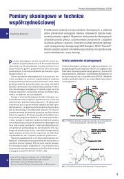
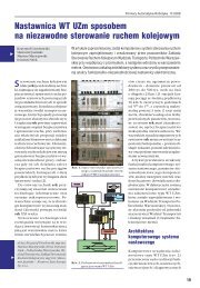
The <strong>inspection</strong> <strong>robot</strong> is constructed from tubular elements<br />
allowing for the wheelbase change. Crawler track tracks<br />
were used to the drive with developed transmission gears<br />
and propellers, their structure allows for works up to 30 m<br />
<strong>underwater</strong>. Additionally the <strong>robot</strong> is equipped with the<br />
diagnostic-monitoring module used for observation the tank<br />
above the <strong>robot</strong> height. Equipped is with 3 cameras (2 for<br />
observation, 1 for the docking with home station), 2 rotating<br />
drives and sensors laser.<br />
1. Introduction<br />
The project <strong>of</strong> <strong>robot</strong> for <strong>inspection</strong> and diagnostics <strong>of</strong> tanks<br />
with liquids is constructed at the Department <strong>of</strong> Robotics<br />
and Mechatronic <strong>of</strong> AGH. It’s created in cooperation with<br />
the Municipal Enterprise MPWiK SA <strong>of</strong> water supply systems<br />
and sewage system. Its aim is to develop the original<br />
construction <strong>of</strong> <strong>inspection</strong> machine enabling to determine<br />
the technical condition <strong>of</strong> concrete construction <strong>of</strong> storage<br />
liquid tanks (most <strong>of</strong>ten water). The design fundamental<br />
assumption: work in conditions <strong>of</strong> souse in liquid at depths<br />
up to several.<br />
Fulfilling this assumption will have a fundamental influence<br />
on the reduction costs <strong>of</strong> the <strong>inspection</strong> procedure because<br />
existing methods require most <strong>of</strong>ten emptying tanks,<br />
what carries behind long (about one month) stoppages.<br />
It next burdens the company budget, which is forced to<br />
turn <strong>of</strong>f the tank/s from use.<br />
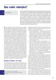
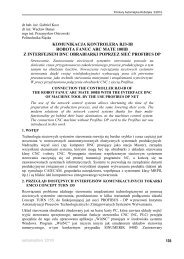
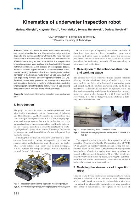
Fig. 2. Tanks for storing water – MPWiK Cracow<br />
Rys. 2. Zbiorniki do magazynowania wody pitnej – MPWiK SA<br />
Kraków<br />
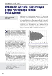
The <strong>inspection</strong> <strong>robot</strong> is intended for diagnostics and observation<br />
<strong>of</strong> tanks with liquids. Cooperation with MPWiK<br />
SA in Cracow [7] enables verifications and testing the constructed<br />
<strong>robot</strong> in real terms. Cracow water supply systems<br />
have a dozen <strong>of</strong> tanks for storing water (among others the<br />
biggest in Europe about diameter <strong>of</strong> 34 m). They require repeated<br />
reviews and expert opinions, applying the constructed<br />
<strong>robot</strong> will enable to streamline these activities, and will<br />
reduce the costs <strong>of</strong> these type actions.<br />
3. Modeling the kinematics <strong>of</strong> <strong>inspection</strong><br />
<strong>robot</strong><br />
Fig. 1. Inspection <strong>robot</strong> with the diagnostic-monitoring module<br />
Rys. 1. Robot inspekcyjny z modułem diagnostyczno-obserwacyjnym<br />
Crawler track driving systems are arrangements, to which<br />
involves a different type <strong>of</strong> variables in time. Description<br />
<strong>of</strong> the crawler track movement in real conditions with uneven<br />
ground on changeable parameters, is very complex.<br />
The detailed mathematical description <strong>of</strong> the move <strong>of</strong><br />
112
For the description <strong>of</strong> motion points on the<br />
crawler track circumference for the simplified<br />
model (fig. 6) two systems <strong>of</strong> coordinates were<br />
accepted. Arrangements y, z is the motionless<br />
arrangement associated with the ground, arrangement<br />
y 0<br />
, z 0<br />
is movable arrangement associated<br />
with vehicle [1, 2, 5, 6].<br />
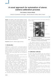
Fig. 3. a) CAD Model, b) Simplified Model<br />
Rys. 3. a) Model CAD, b) Model uproszczony<br />
individual crawler track points is so compound that it<br />
is necessary to apply simplified models. Crawler tracks<br />
(fig. 3a) in the very simplification it is possible to model,<br />
as the non-stretch tape about determined shape by the<br />
drive wheel, stretching wheel and no deformable ground<br />
(fig. 3b) [1–4].<br />
Apart from widely applied crawler tracks constructed<br />
from links, appear also crawler tracks made from the elastomer<br />
belt. They constitute one element along with clutches.<br />
Driving arrangement <strong>of</strong> the analyzed crawler track<br />
<strong>robot</strong> are two driving modules (fig. 4).<br />
Specifications:<br />
––<br />
height: 100 mm,<br />
––<br />
width: 90 mm,<br />
––<br />
length: 380 mm,<br />
––<br />
speed up to 9.75 m/min,<br />
––<br />
maximum load: 45 kg,<br />
––<br />
water resistance to the depth 30 m,<br />
––<br />
mass: stainless steel 12.25 kg.<br />
Fig. 6. Simplified model <strong>of</strong> the crawler track track<br />
Rys. 6. Uproszczony model gąsienicy<br />
The movement <strong>of</strong> any crawler track point is composition<br />
<strong>of</strong> two movements (fig. 6):<br />
––<br />
relative move, <strong>of</strong> the agreement y 0<br />
, z 0<br />
,<br />
––<br />
transportation move relative to the immovable arrangement<br />
y, z.<br />
The absolute speed <strong>of</strong> any point on the crawler track<br />
circumference is equal to the sum <strong>of</strong> geometrical transportation<br />
speed and relative speed.<br />
V<br />
by=V u+Vtcosϕ (1)<br />
V =V sinϕ (2)<br />
bz<br />
t<br />
2 2 2 2<br />
V<br />
b= V<br />
by+V bz<br />
= V<br />
u<br />
+V<br />
t<br />
+2Vu Vtcosϕ (3)<br />
Fig. 4. Crawler tracks – model CAD<br />
Rys. 4. Gąsienice – model CAD<br />
where: V u<br />
– speed <strong>of</strong> transportation, V t<br />
– relative speed<br />
<strong>of</strong> any point on the crawler track circumference, V b<br />
–<br />
absolute speed <strong>of</strong> the point on crawler track circumference,<br />
j – angle between vectors V t<br />
and V u<br />
.<br />
In case when j = p, that is when points <strong>of</strong> the crawler<br />
track circumference contact with the ground, it is possible<br />
to write.<br />
V<br />
b=V u+V (4)<br />
t<br />
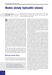
Basic inside sub-assemblies<br />
(fig. 5) <strong>of</strong> each module:<br />
––<br />
driving engine<br />
––<br />
planetary transmission<br />
––<br />
conical transmission<br />
––<br />
leading transmission<br />
Individual ratio <strong>of</strong> these transmissions:<br />
i 1<br />
= 66 : 1 – transferring<br />
the planetary transmission,<br />
i 2<br />
= 2 : 1 – transferring<br />
the conical transmission,<br />
i 3<br />
= 2 : 1 – transferring<br />
the leading transmission.<br />
Total ratio the driving module:<br />
i = 264 : 1.<br />
Fig. 5. Drivetrain<br />
Rys. 5. Układ przeniesienia napędu<br />
3.1. Slide crawler track<br />
When transferring <strong>of</strong> the loadbearing<br />
crawler track segment<br />
appears relative to ground,<br />
then the effect <strong>of</strong> slip occurs<br />
[1, 5, 6]. Mainly for the crawler<br />
track slide affects the following<br />
factors:<br />
––<br />
ownerships <strong>of</strong> the ground,<br />
––<br />
appearing driving force,<br />
––<br />
type and placing clutches<br />
on the crawler track track.<br />
Appearing in the crawler<br />
track arrangement, the driving<br />
force causes appear <strong>of</strong> cutting<br />
powers in the ground. The re-<br />
Pomiary Automatyka Robotyka nr 12/2012<br />
113
Nauka<br />
lationship between appearing factors it is<br />
possible to determine relations by:<br />
L<br />
6<br />
Pn<br />
10 b τxdx<br />
0<br />
= ∫ (5)<br />
where: P n<br />
– driving force, b – width <strong>of</strong> the<br />
crawler track, L – length <strong>of</strong> the load-bearing<br />
<strong>of</strong> the crawler track segment, t x<br />
– stresses<br />
cutting in the s<strong>of</strong>t ground.<br />
Assuming that the course <strong>of</strong> parallel deformations<br />
to the ground is linear, it is possible<br />
to express these deformations by:<br />
∆ l = xs<br />
(6)<br />
x<br />
where: s b<br />
– slip, x – distance <strong>of</strong> the place, for which the<br />
slip is calculated from the point <strong>of</strong> crawler track contact<br />
with ground, the greatest slip appears for x = L.<br />
Therefore, it is possible to express the slip by:<br />
∆l<br />
x<br />
b<br />
∆l<br />
L<br />
x max<br />
b<br />
= = (7)<br />
s<br />
3.2. <strong>Kinematics</strong> <strong>of</strong> turning<br />
It is possible to define the turn <strong>of</strong> crawler track vehicle as<br />
the flat movement, which is a sequence <strong>of</strong> turns around<br />
next momentary axes <strong>of</strong> rotation. The center <strong>of</strong> turn creates<br />
tracks on the plain <strong>of</strong> next rotation axes and it can<br />
be fixed point for the movement about constant radius<br />
or line.<br />
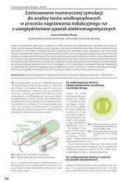
Turn in crawler track vehicles depending on the direction<br />
and value <strong>of</strong> driving forces and braking (P 2<br />
and P 1<br />
)<br />
can be carried out in few ways.<br />
When the speed <strong>of</strong> running crawler track is reduced in<br />
the relationship to run (fig. 8a) by braking, a turn appears<br />
about the small radius R. On running crawler tracks<br />
then operate oblong tangent forces about direction opposite<br />
direction to the movement <strong>of</strong> the crawler track vehicle.<br />
In that kind <strong>of</strong> turn on the vehicle operate two forces,<br />
brake force P 1<br />
in the running crawler track and driving<br />
force P 2<br />
about the direction <strong>of</strong> vehicle movement in the<br />
running crawler track.<br />
In case <strong>of</strong> disconnection the running crawler track drive<br />
(fig. 8b) appears turn about the great radius. Then only<br />
P 2<br />
force <strong>of</strong> the running crawler track appears.<br />
Fig. 8. Possible variants <strong>of</strong> the crawler track vehicle turn<br />
Rys. 8. Możliwe warianty skrętu pojazdu gąsienicowego<br />
At appearance <strong>of</strong> great resistances progressive move<br />
and low resistances <strong>of</strong> the turn, may appear case that P 1<br />
force <strong>of</strong> the running crawler track have direction in accordance<br />
with direction <strong>of</strong> the ride (fig. 8c).<br />
3.3. <strong>Kinematics</strong> equation<br />
Prędkość punktu C, znajdującego się na osi symetrii<br />
pojazdu gąsienicowego, przyjętego jako środek masy<br />
pojazdu [1–3, 5, 6], wynosi:<br />
V<br />
rα<br />
(1 − s ) + r α (1 + s )<br />
2<br />
1 1 2 2 2<br />
C<br />
= ̇ ̇ (8)<br />
Nie uwzględniając poślizgu:<br />
V<br />
rα<br />
+ rα<br />
2<br />
1 2<br />
C<br />
= ̇ ̇ (9)<br />
Components <strong>of</strong> the speed point C it is possible to write<br />
as:<br />
ẋ = V cos b<br />
(10)<br />
C<br />
C<br />
ẏ = V sin b<br />
(11)<br />
C<br />
After taking into account the relation (8) received the<br />
equation <strong>of</strong> simple kinematic task:<br />
C<br />
rα<br />
(1 − s ) + rα<br />
(1 − s )<br />
= ̇ ̇ cos<br />
2<br />
1 1 2 2<br />
ẋ C<br />
b (12)<br />
Fig. 7. Kinematic diagram <strong>of</strong> the crawler track vehicle turn<br />
without a slip<br />
Rys. 7. Schemat kinematyczny skrętu pojazdu gąsienicowego<br />
bez poślizgu<br />
Fig. 9. Diagram <strong>of</strong> the frame <strong>robot</strong> turn for the angle b<br />
Rys. 9. Schemat obrotu ramy <strong>robot</strong>a o kąt b<br />
114
α<br />
(1 − s ) + rα<br />
(1 − s )<br />
= ̇ ̇ sin<br />
2<br />
̇ rα2(1 − s2) − rα1(1 − s1)<br />
b = ̇ ̇<br />
(14)<br />
H<br />
1 1 2 2<br />
ẏ C<br />
b (13)<br />
Based on the relation (12) and (13) it is possible to<br />
write as the equation <strong>of</strong> reverse kinematics tasks:<br />
V = ẋ + ẏ (15)<br />
2 2<br />
C C C<br />
̇ H<br />
ȧ (16)<br />
VC<br />
-0,5 ⋅ b<br />
1= r ( 1-s<br />
1)<br />
̇ H<br />
ȧ (17)<br />
V<br />
C+0,5<br />
⋅ b<br />
2= r ( 1-s<br />
2)<br />
Considering correlations <strong>of</strong> the transmission crawler<br />
track arrangement:<br />
1<br />
1s=<br />
1<br />
264 ȧ ȧ<br />
(18)<br />
1<br />
264 a a<br />
̇ 2s=<br />
̇ 2<br />
(19)<br />
where: ȧ<br />
1s<br />
– angular speed on the shaft <strong>of</strong> driving engine<br />
running crawler track, ȧ<br />
2s<br />
– angular speed on the shaft <strong>of</strong><br />
driving engine running crawler track<br />
Substituting (16) and (17) to (18) and (19) received relations<br />
on the angular speeds <strong>of</strong> driving engines:<br />
1s<br />
( C<br />
⋅ )<br />
r( 1-s )<br />
264 V -0,5 H<br />
ȧ =<br />
(20)<br />
2s<br />
1<br />
( C<br />
⋅ )<br />
r( 1-s )<br />
264 V +0,5 H<br />
ȧ =<br />
(21)<br />
2<br />
4. Numerical verification <strong>of</strong> the<br />
kinematics model<br />
In many cases during the <strong>inspection</strong> work the zone <strong>of</strong> <strong>robot</strong><br />
action isn’t limited to horizontal planes. Many times the<br />
<strong>robot</strong> must defeat different heights and therefore in order<br />
to obtain more comprehensive analysis <strong>of</strong> the kinematics<br />
<strong>robot</strong> must carry it also in case <strong>of</strong> the move after the hill.<br />
For the numerical verification the following assumptions<br />
were made. The <strong>robot</strong> moves on the segment about g gradient,<br />
at equal angular speeds <strong>of</strong> driving wheels V u1<br />
= V u2<br />
, slip<br />
s 1<br />
= s 2<br />
= s then the equations <strong>of</strong> movement will adopt the form:<br />
264( VC<br />
-0,5 ⋅ H)<br />
264( V<br />
C+0,5 ⋅ H)<br />
ȧ 1s<br />
=<br />
, ȧ<br />
'<br />
2s<br />
=<br />
'<br />
⎛ ( n-1)<br />
Dl<br />
⎞<br />
⎛ ( n-1)<br />
Dl<br />
⎞<br />
r ⎜1-<br />
⎝<br />
L<br />
⎟<br />
⎠<br />
r ⎜1-<br />
⎝<br />
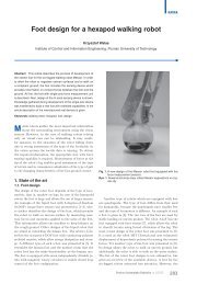
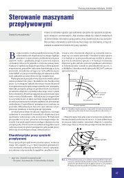
Assuming that its point C moves on the trajectory<br />
(fig. 10a), with the speed course (fig. 10b).<br />
Received courses for the set trajectory and speed <strong>of</strong> the<br />
point C.<br />
Fig. 10. a) Set motion track <strong>of</strong> the point C, b) set speed course<br />
<strong>of</strong> the point C<br />
Rys. 10. a) Założony tor ruchu punktu C, b) założony przebieg<br />
prędkości punktu C<br />
L<br />
⎟<br />
⎠<br />
Vc [m/s]<br />
0.16<br />
0.14<br />
0.12<br />
0.1<br />
0.08<br />
0.06<br />
0.04<br />
0.02<br />
0<br />
0 5 10 15 20<br />
t [s]<br />
Fig. 11. Set speed <strong>of</strong> the point C<br />
Rys.11. Prędkość zadana punktu C<br />
alfa*1, alfa*2 [rad/s]<br />
3.5<br />
3<br />
2.5<br />
2<br />
1.5<br />
1<br />
0.5<br />
0<br />
0 5 10 15 20<br />
t [s]<br />
Fig. 13. Angular speed <strong>of</strong> crawler tracks<br />
Rys. 13. Prędkość kątowa kół napędzających gąsienice<br />
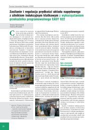
alfa*1s, alfa*2s [rad/s]<br />
1000<br />
800<br />
600<br />
400<br />
200<br />
0<br />
0 5 10 15 20<br />
t [s]<br />
Fig. 12. Angular speed on shafts <strong>of</strong> driving engines<br />
Rys.12. Prędkość kątowa na wałach silników napędowych<br />
Vco [m/s]<br />
0.16<br />
0.14<br />
0.12<br />
0.1<br />
0.08<br />
0.06<br />
0.04<br />
0.02<br />
0<br />
0 5 10 15 20<br />
t [s]<br />
Fig. 14. Received speed driving wheels<br />
Rys.14. Prędkość otrzymana<br />
Pomiary Automatyka Robotyka nr 12/2012<br />
115
Nauka<br />
5. Summary<br />
Equations <strong>of</strong> the kinematics <strong>inspection</strong> <strong>robot</strong> were drawn<br />
up correctly, simulation examinations confirmed it. The<br />
numerical verification showed influence <strong>of</strong> the slip on<br />
behavior <strong>of</strong> the <strong>robot</strong>. As can be observed for increasingly<br />
larger set disposable horizontal deforming ground or<br />
clutch, the speed <strong>of</strong> slip increases its value. More considerable<br />
value assumes also received speed <strong>of</strong> the point C in<br />
order to ensure the set speed. However, the increase speed<br />
in fact is limited by parameters <strong>of</strong> the driving arrangement<br />
(rotation speed, engine power driving) what leads to<br />
situation that the <strong>robot</strong> starts to move with smaller lost<br />
speed in aid <strong>of</strong> the slip speed.<br />
Bibliography<br />
1. Burdziński Z., Teoria ruchu pojazdu gąsienicowego,<br />
Wydawnictwa Komunikacji i Łączności, Warszawa<br />
1972.<br />
2. Dajniak H., Ciągniki teoria ruchu i konstruowanie,<br />
Wydawnictwa Komunikacji i Łączności, Warszawa<br />
1985.<br />
3. Żylski W., Kinematyka i dynamika mobilnych <strong>robot</strong>ów<br />
kołowych, Oficyna Wydawnicza Politechniki Rzeszowskiej,<br />
Rzeszów 1996.<br />
4. Trojnacki M.: Modelowanie i symulacja ruchu mobilnego<br />
<strong>robot</strong>a trzykołowego z napędem na przednie koła<br />
z uwzględnieniem poślizgu kół jezdnych, „Modelowanie<br />
Inżynierskie”, Tom 10, Nr 41, 411–420, ISSN 1896-<br />
771X, Gliwice 2011.<br />
5. Chodkowski A.W., Badania modelowe pojazdów gąsienicowych<br />
i kołowych, Wydawnictwa Komunikacji<br />
i Łączności, Warszawa 1982.<br />
6. Chodkowski A.W., Konstrukcja i obliczanie szybkobieżnych<br />
pojazdów gąsienicowych, Wydawnictwa Komunikacji<br />
i Łączności, Warszawa 1990.<br />
7. Documentation made available by MPWiK SA Krakow<br />
[www.wodociagi.krakow.pl].<br />
Kinematyka podwodnego<br />
<strong>robot</strong>a inspekcyjnego<br />
Streszczenie: W artykule przedstawiono zagadnienia związane<br />
z modelowaniem i weryfikacją numeryczną kinematyki <strong>robot</strong>a<br />
inspekcyjnego do diagnostyki i konserwacji zbiorników z cieczą.<br />
Robot zbudowany został w Katedrze Robotyki i Mechatroniki<br />
AGH w ramach grantu finansowanego przez NCBiR. Analizę<br />
kinematyczną przeprowadzono przy użyciu dostępnych i opisanych<br />
w literaturze metod matematycznych oraz na podstawie<br />
istniejących konstrukcji <strong>robot</strong>ów. Zastosowane rozwiązania konstrukcyjne<br />
pozwalają sterować dwoma gąsienicami, modułem<br />
czyszczenia dna zbiornika i modułem diagnostycznym. Weryfikację<br />
kinematyki przeprowadzono przy użyciu metod inżynierskich<br />
oraz oprogramowania MATLAB. Otrzymane wyniki przedstawiono<br />
w postaci równań matematycznych oraz charakterystyk pokazujących<br />
kinematyczne parametry ruchu <strong>robot</strong>a. Praca przedstawia<br />
również kierunki dalszych badań nad zaprojektowanym<br />
i skonstruowanym <strong>robot</strong>em.<br />
Słowa kluczowe: mobilne <strong>robot</strong>y, kinematyka, <strong>robot</strong>y inspekcyjne,<br />
<strong>robot</strong>y podwodne<br />
Pr<strong>of</strong>. Mariusz Giergiel, PhD<br />
He was born in 1961 in Cracow, Poland.<br />
He was graduated in 1985 at AGH University<br />
<strong>of</strong> Science and Technology in field <strong>of</strong><br />
electronics automatics. In 1992 earned his<br />
doctoral degree in field <strong>of</strong> mechanics at the<br />
same University. Since 2005 he is pr<strong>of</strong>essor<br />
at AGH UST at Faculty <strong>of</strong> Mechanical Engineering<br />
and Robotics. Works in filed <strong>of</strong> automatics<br />
and <strong>robot</strong>ics, applied mechanics and<br />
mechatronics. Currently is research manager<br />
<strong>of</strong> group working on project <strong>of</strong> <strong>underwater</strong><br />
tank <strong>inspection</strong> <strong>robot</strong>s. Member <strong>of</strong><br />
local and international scientific societies, author <strong>of</strong> many publications,<br />
patents, developed researches and applied solutions.<br />
e-mail: giergiel@agh.edu.pl<br />
Krzyszt<strong>of</strong> Kurc, PhD<br />
In 1999 graduated from technical school<br />
in electronics Krosno, in 2004, graduated<br />
from the Faculty <strong>of</strong> Mechanical Engineering<br />
and Aeronautics, Rzeszow University<br />
<strong>of</strong> Technology. Since 2004, working<br />
in the Department <strong>of</strong> Applied Mechanics<br />
and Robotics, Rzeszow University <strong>of</strong> Technology.<br />
Research interests include mechatronics,<br />
<strong>robot</strong>ics, mechanics, design.<br />
e-mail: kkurc@prz.edu.pl<br />
Piotr Małka, PhD<br />
He received MSc degree in Robotics and<br />
Automatics from the Faculty <strong>of</strong> Mechanical<br />
Engineering and Robotics, AGH University<br />
<strong>of</strong> Science and Technology in 2001, the PhD<br />
degree in 2008 also at AGH University. He<br />
is currently employed at Municipal Waterworks<br />
and Sewer Enterprise, holds the<br />
position <strong>of</strong> manager for the automation. His<br />
main research area is connected with industrial<br />
and mobile <strong>robot</strong>s, fuzzy logic applications,<br />
modelling and identification <strong>of</strong> mechatronic<br />
systems.<br />
e-mail: malka@agh.edu.pl<br />
Tomasz Buratowski, PhD<br />
He received MSc degree in Robotics and<br />
Automatics from the Faculty <strong>of</strong> Mechanical<br />
Engineering and Robotics, AGH University<br />
<strong>of</strong> Science and Technology in 1999, the PhD<br />
degree in 2003 also at AGH University. He<br />
is currently employed at AGH university as<br />
an assistant pr<strong>of</strong>essor. His main research<br />
area is connected with industrial and mobile<br />
<strong>robot</strong>s and also human-<strong>robot</strong> interaction,<br />
fuzzy logic applications, modelling and identification<br />
<strong>of</strong> mechatronic systems.<br />
e-mail: tburatow@agh.edu.pl<br />
Dariusz Szybicki, MSc<br />
He was born in Przeworsk. He graduated<br />
from the University <strong>of</strong> Rzeszów, where in<br />
2009 he started engineering doctoral studies<br />
at the Faculty <strong>of</strong> Mechanical Engineering<br />
and Aeronautics. He works as an assistant<br />
in the Department <strong>of</strong> Applied Mechanics<br />
and Robotics at the Technical University<br />
<strong>of</strong> Rzeszów. His research interests relate<br />
to <strong>robot</strong>ics, programming, and modeling <strong>of</strong><br />
mechatronic systems.<br />
e-mail: dszybicki@prz.edu.pl<br />
116