Plexineon® Installation Manual - iLight Technologies
Plexineon® Installation Manual - iLight Technologies
Plexineon® Installation Manual - iLight Technologies

You also want an ePaper? Increase the reach of your titles
YUMPU automatically turns print PDFs into web optimized ePapers that Google loves.
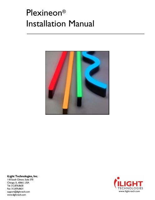
Plexineon ®<br />
<strong>Installation</strong> <strong>Manual</strong><br />
<strong>iLight</strong> <strong>Technologies</strong>, Inc.<br />
118 South Clinton, Suite 370<br />
Chicago, IL. 60661, USA<br />
Tel: 312.876.8630<br />
Fax: 312.876.8631<br />
support@ilight-tech.com<br />
www.ilight-tech.com<br />
www.ilight-tech.com
Nov 2009<br />
F422-020C
Table of Contents<br />
PLEXINEON QUICK INSTALL TIPS<br />
ABOUT THIS GUIDE ..............................................................1: 1<br />
• Documentation Copyright .............................................................. 1<br />
• Copyright, Trademark, and Patent Laws ....................................... 1<br />
• MET Laboratories Listing................................................................ 1<br />
• Partnerships...................................................................................... 1<br />
• Customer Service ............................................................................ 1<br />
• Services ............................................................................................. 1<br />
• Conventions ...................................................................................... 1<br />
Safety Symbols and Information ............................................................................... 2<br />
INSTALLATION MANUAL.....................................................2: 1<br />
• Warranty Notice .............................................................................. 1<br />
• Plexineon Product Description....................................................... 1<br />
• Terminology...................................................................................... 1<br />
• <strong>Installation</strong> Qualification Area........................................................ 1<br />
• Tools Required for Installing Hardware ......................................... 1<br />
• Prepare <strong>Installation</strong> Area ................................................................ 2<br />
Layout of <strong>Installation</strong>................................................................................................... 2<br />
• <strong>Installation</strong> ........................................................................................ 3<br />
Mark Area ......................................................................................................................3<br />
Plexineon Fixtures....................................................................................................... 3<br />
Clip Placement with Drill .................................................................................................3<br />
Fastening Tips.......................................................................................................................3<br />
Install Plexineon Fixtures into Clips.............................................................................. 4<br />
Plexineon Bends........................................................................................................... 6<br />
Cuttable Plexineon ..................................................................................................... 6<br />
Cutting Fixtures ..................................................................................................................6<br />
Corner Cuttable ....................................................................................................... 7<br />
Install Power Supplies ................................................................................................. 7<br />
Connecting the Plexineon Fixtures ........................................................................ 9<br />
Connect the Plexineon Fixtures to the Power Supplies ................................. 10<br />
Corners ...................................................................................................................... 11<br />
• <strong>Installation</strong> Tips ............................................................................. 11<br />
Timer ............................................................................................................................ 11<br />
Storing Plexineon Before <strong>Installation</strong> ................................................................... 12<br />
Starting <strong>Installation</strong>..................................................................................................... 12<br />
• Maintenance and Cleaning ........................................................... 12<br />
Cleaning of Plexineon ............................................................................................... 12<br />
Checking on Power Supply...................................................................................... 12<br />
• Troubleshooting ............................................................................. 12<br />
An Entire Run of Plexineon Won’t Illuminate...................................................... 12<br />
Half a Run of Plexineon Won’t Illuminate .......................................................... 12<br />
Plexineon Flickers ..................................................................................................... 13<br />
Plexineon Cycles On and Off ................................................................................. 13<br />
Individual Fixture is Inoperable .............................................................................. 13<br />
Nov 2009<br />
F422-020C
About this Guide<br />
Documentation<br />
Copyright<br />
Copyright,<br />
Trademark, and<br />
Patent Laws<br />
MET<br />
Laboratories<br />
Listing<br />
Partnerships<br />
Customer<br />
Service<br />
Services<br />
<strong>iLight</strong> <strong>Technologies</strong> © 2008. All rights reserved. No part of this documentation may be reproduced in<br />
any form or by any means or used to make any derivative work (such as translation, transformation,<br />
or adaptation) without written permission from <strong>iLight</strong> <strong>Technologies</strong>, Inc.<br />
<strong>iLight</strong> <strong>Technologies</strong> reserves the right to revise this documentation and to make changes in content<br />
from time to time without obligation on the part of <strong>iLight</strong> <strong>Technologies</strong>, Inc. to provide notification of<br />
such revision or change.<br />
<strong>iLight</strong> <strong>Technologies</strong> provides this documentation without warranty of any kind, either implied or<br />
expressed, including, but not limited to, the implied warranties of merchantability and fitness for a<br />
particular purpose. <strong>iLight</strong> <strong>Technologies</strong> may make improvements or changes in the product(s) and/<br />
or the program(s) described in this documentation at any time.<br />
<strong>iLight</strong> <strong>Technologies</strong>, <strong>iLight</strong>, Plexineon and Hypnotica are either registered trademarks of <strong>iLight</strong><br />
<strong>Technologies</strong>, Inc. in the United States and/or other countries.<br />
Other brand and product names may be registered trademarks or trademarks of their respective<br />
holders.<br />
Unauthorized modifications may be illegal under international law. This principle also applies to<br />
<strong>iLight</strong> <strong>Technologies</strong>’ logos, designs, publications, and assemblies.<br />
The MET Laboratories Listing has been completed and appears on all luminaires. <strong>iLight</strong>’s Plexineon<br />
is compliant to UL 1598 and CSA c22.2 No. 250 in Luminairies for installations in wet environments.<br />
Partnerships have been established with the following companies:<br />
• Pathway Connectivity<br />
http://www.pathwayconnect.com/<br />
• Fleenor Design<br />
http://www.dfd.com/<br />
• OSRAM<br />
http://www.osram.com/osram_com/index.html<br />
<strong>iLight</strong> <strong>Technologies</strong> is ready to help. Contact our service number at 312.876.8630 or at<br />
support@ilight-tech.com.<br />
The following service is offered from <strong>iLight</strong> <strong>Technologies</strong>, Inc:<br />
• Technical Support: A service technician can be provided for teleconference, on-line or on-site<br />
to instruct your installation team on how to properly install Plexineon and Hypnotica products.<br />
This training includes review of the site plan, proper layout of <strong>iLight</strong> product, power supplies, clip<br />
placement, cable dress issues, proper techniques for cutting the cuttable fixtures and<br />
troubleshooting. This does not include actual installation of the <strong>iLight</strong> product or connection to<br />
the main power supply systems.<br />
Conventions<br />
For clarity, this Service <strong>Manual</strong> uses the following conventions:<br />
Nov 2009<br />
F422-020C
1-2 About this Guide<br />
Safety Symbols and<br />
Information<br />
When required, information is provided in procedures about potential challenges and dangers. The<br />
terms WARNING, CAUTION, and NOTICE are used for specific safety reasons. For emphasis,<br />
WARNING and CAUTION appear beside the characteristic triangle symbol. Table 1 lists notice<br />
icons used in this guide.<br />
Table 1 Notice Icon Descriptions<br />
Icon/Format<br />
NOTE:<br />
Description<br />
Information note about important features or instructions but is not critical data.<br />
NOTICE:<br />
Notice indicates a situation that requires special attention.<br />
CAUTION:<br />
Caution alerts you to potential damage to a program, system, or device.<br />
WARNING:<br />
Warning indicates a situation the may cause personal injury or death.<br />
WARNING:<br />
Warning indicates a situation the may cause personal injury or death due to a<br />
potential electrical hazard.<br />
ESD:<br />
ESD alerts you to take proper grounding precautions against electrostatic<br />
discharge (ESD) before handling a product.<br />
Nov 2009
<strong>Installation</strong> <strong>Manual</strong><br />
Warranty<br />
Notice<br />
Plexineon<br />
Product<br />
Description<br />
Terminology<br />
This product is sold pursuant to <strong>iLight</strong> <strong>Technologies</strong>, Inc.’s standard terms and conditions as stated<br />
in the warranty. The warranty can be found at:<br />
http://www.ilight-tech.com/tech_warranty.htm<br />
Plexineon is the next generation LED lighting solution that creates a bright, even glow across the<br />
surface of the product. Designed to go outdoors in wet locations, Plexineon offers unsurpassed<br />
durability for both exterior and interior applications. Available in standard straight lengths, custom<br />
lengths, field cuttable fixtures, and specialty bends and corners, Plexineon will meet your lighting<br />
needs. The Plexineon fixtures are easy to install and mount with our all-weather connectors,<br />
mounting clips, and low voltage power supplies.<br />
Table 2-1 Terminology Used in the <strong>Manual</strong><br />
Term<br />
Lead-in Wire<br />
Run<br />
Description<br />
The total length of wire that can be used to connect the power supply to the<br />
Plexineon fixtures.<br />
Composed of lead-in wire and fixtures of Plexineon connected to a single output on the<br />
power supply.<br />
<strong>Installation</strong><br />
Qualification<br />
Area<br />
Tools Required<br />
for Installing<br />
Hardware<br />
This installation guide is designed to instruct and aid in the installation of Plexineon products.<br />
<strong>Installation</strong> of Plexineon should be done by a skilled tradesperson familiar with construction and<br />
electrical installation techniques. Licensed electricians should provide all installation and electrical<br />
primary inputs for the Plexineon power supply. <strong>Installation</strong> should be done in accordance with all<br />
National and Local codes and ordinances.<br />
NOTE: <strong>Installation</strong> of Plexineon systems in harsh environments where there are chemicals, high<br />
winds or vibrations has not been tested and may result in failure and void warranty.<br />
NOTE: Please refer to Product Specification Sheets for allowable operating conditions on the <strong>iLight</strong><br />
Web site.<br />
• Cordless Drill<br />
• 3/16" Drill Bit<br />
• 3/16" Stainless Steel Screws (#10 or #12), masonry anchor or short rivets (depending on the<br />
mounting surface)<br />
• Masonry Anchor or Insert (for installation into brick, stucco or concrete)<br />
• Rivet Gun (for installation in metal)<br />
• 3/16" x 1/4" rivets (if installing into metal)<br />
• # 2 Phillips Driver Bits (recommended 1 1/2" long bits for screw guns)<br />
• Wire Stripper<br />
• Flathead Screwdriver<br />
• Needle Nose Pliers<br />
• Measuring Tape<br />
• Chalk Line (or other marking mechanism)<br />
• Power Miter Saw / Chop Saw / Hack Saw<br />
• Silicone Sealant (electronic grade, non-conducive, non-corrosive)<br />
• Wire Nut Connectors or Electrical Tape<br />
• AC / DC Volt Ammeter (multimeter)<br />
Nov 2009<br />
F422-020C
2-2 <strong>Installation</strong> <strong>Manual</strong><br />
Prepare<br />
<strong>Installation</strong> Area<br />
Layout of<br />
<strong>Installation</strong><br />
Layout of the product should be considered prior to installation. Consider the following points when<br />
creating the layout.<br />
• This lighting system, including the power unit, AC cord, lead-in wire and Plexineon product can<br />
not be installed in environmental air handling systems (i.e. the area above a drop ceiling used for<br />
supply or return).<br />
• Each fixture length has a recommended amount and location of clips that should be used to<br />
properly install the fixture. Review Table 2-2 and Figure 2-1 for those specifications.<br />
Table 2-2 Plexineon Length and Amount of Clips with and without C-Channel<br />
Amount of Clips with Amount of Clips without<br />
Plexineon Length<br />
Channel<br />
C-Channel<br />
8’-0" (2.438 m) 5 8<br />
6’-0" (1.828 m) 4 6<br />
4’-0" (1.219 m) 3 4<br />
2’-0" (609 mm) 2 3<br />
Outside Corner 3 3<br />
NOTE: Do not install the Plexineon fixtures flat so they will be submerged when it rains. <strong>iLight</strong> offers<br />
a specialty "L" tab clip to lift fixtures off of surface to prevent submersion.<br />
WARNING: Removal of C-Channel voids warranty.<br />
Figure 2-1 Location of Clips<br />
Nov 2009
<strong>Installation</strong><br />
NOTE: When using 3" Joiner clips, standard clips are not required between Plexineon fixtures.<br />
2-3<br />
• Power supplies must be mounted within forty feet (12.19 m) of the first Plexineon fixture (if 14<br />
AWG wire is used). The calculation of 40 feet (12.19 m) is only good if the Plexineon is installed<br />
“end to end.” If a large jump needs to be made from one fixture to another, (i.e. around a corner)<br />
then that distance needs to be subtracted from the forty feet (12.19 m).<br />
• The total length in wire used on any given run is 40 feet (12.192 m) when using 14 AWG wire.<br />
However, if using a larger gauged wire, the lead-in wire length can be greater. Refer to Table 2-3<br />
for more information.<br />
Table 2-3 Power Wire and Total Allowable Length<br />
Gauge of Wire<br />
Total Lead-in Wire Allowable Length<br />
10 100 Ft (30.48 m)<br />
12 60 Ft (18.29 m)<br />
14 40 Ft (12.19 m)<br />
• The maximum amount of Plexineon fixtures can be used for each lead-in wire per 100 watt<br />
power supply. Refer to Table 2-4 for specifications.<br />
• <strong>iLight</strong> <strong>Technologies</strong> supplies 14 AWG wire. If the lead-in distance is longer than 40 feet (12.19 m)<br />
then a larger gauge (UV rated/outdoor rated) wire is needed.<br />
Table 2-4 Maximum Amount of Feet per Run Using a 100 Watt Power Supply<br />
Linear Dimension of Plexineon Run<br />
Plexineon Light Color<br />
48 Feet (14.6 m) Red, Amber and Orange<br />
32 Feet (9.8 m) White 1X, Blue, Teal, Green and<br />
Magenta<br />
20 Feet (6.10 m) White 2X<br />
• For all fixtures a 3/8" (10 mm) gap (which is one finger width) should be placed between<br />
Plexineon fixtures. Temperature changes cause expansion and contraction of the fixtures which<br />
may cause the fixtures to break if they are too close to each other and will void warranty.<br />
<strong>Installation</strong><br />
Mark Area<br />
Plexineon Fixtures<br />
Use the layout (as a reference) and the chalk line (or other marking mechanism) to mark the<br />
location for the power supplies, fixtures and clips.<br />
Clip Placement with Drill<br />
Plexineon fixtures are mounted using stainless steel spring clips. A 3 inch (76.2 mm) joiner clip can<br />
be used to connect the ends of two fixtures. If not using the joiner clip, the recommeded spacing for<br />
the clips is 2 inches (51 mm) in from each end of the fixture, and one every 18 inches (457 mm),<br />
based on the length of Plexineon fixture. See Figure 2-1 and Table 2-2 for placement diagram. The<br />
Plexineon clips come with a 3/16" (4.8 mm) screw hole. Slip the screw inside clip hole and fasten<br />
tightly to surface (as shown in Figure 2-2).<br />
NOTE: Clips should be mounted at an equal height to make sure Plexineon fixtures are installed<br />
straight.<br />
CAUTION: Clips can have sharp edges and drill operator should use care when mounting clips to<br />
the wall.<br />
NOTE: Refer to <strong>iLight</strong> Web site for different specialty clips.<br />
Fastening Tips<br />
• It is recommended to use an exterior grade fastener (e.g. stainless steel screws).<br />
• If the mounting surface is brick, stucco, or concrete, a masonry anchor should be used (i.e.<br />
Tapcon).<br />
• If clips are attached to metal, it is recommended that 3/16" (4.8 mm) short rivets be used<br />
instead of screws.<br />
F422-020C
2-4 <strong>Installation</strong> <strong>Manual</strong><br />
Figure 2-2 Clip Fastening Illustration<br />
Install Plexineon Fixtures into Clips<br />
NOTE: Before beginning the installation of Plexineon fixtures, the installer should dissipate any<br />
static charge by touching a grounded metal object.<br />
Prepare Plexineon fixture for installation. Position the bottom end of the Plexineon fixture at an angle<br />
and snap into the groove on the lower end of the clip, as the fixture is being positioned within the clip<br />
(as shown in Figure 2-3).<br />
NOTE: Catching the clip in the groove is important. The groove is considered the part between the<br />
frosted curved portion of the front and the side plastic channel. Do not allow the clip to go over the<br />
end of the product.<br />
Push in until the clip catches the groove (as seen in Figure 2-4 and Figure 2-5). Make sure that the<br />
connector(s) are oriented properly. When clips are appropriately mounted, the Plexineon length can<br />
be inserted into the clips. Insert Plexineon one clip at a time.<br />
Figure 2-3 Initial Position of Plexineon<br />
Nov 2009
<strong>Installation</strong><br />
2-5<br />
Figure 2-4 Plexineon in Groove<br />
Figure 2-5 Plexineon in Groove (Side View)<br />
During installation, verify that the Plexineon has space to expand or contract by leaving a 3/8"<br />
(10 mm) gap (about a finger width) between fixtures (as shown in Figure 2-6). This is especially<br />
important if the product is installed in cooler temperatures.<br />
CAUTION: Do not butt the fixtures next to each other for any layout. This will cause service<br />
problems and will void warranty.<br />
Figure 2-6 3/8" (10 mm)Spacing Between Fixtures<br />
Joiner Clip<br />
Standard Clips<br />
F422-020C
2-6 <strong>Installation</strong> <strong>Manual</strong><br />
Plexineon Bends<br />
<strong>iLight</strong> Plexineon fixtures are field bendable. Make sure that the proper bending procedures are used<br />
for the fixture.These fixtures can be field bent in the "easy" direction. The "easy" direction is the<br />
bend axis parallel to the light direction.<br />
NOTE: Bending of fixtures is done without the supportive C-Channel.<br />
Table 2-5 Minimum Radius for Field Bending of Fixtures<br />
Fixture Type<br />
Plexineon Colors and White 1X Series<br />
Plexineon White 2X Series<br />
Minimum Radius For Field Bending*<br />
48 inch (1219 mm)<br />
72 inch (1829 mm)<br />
* Diagram available on Web site.<br />
NOTE: For more information about bend radii, please refer to the <strong>iLight</strong> Web site.<br />
Cuttable Plexineon<br />
<strong>iLight</strong>’s cuttable fixtures come in a variety of colors and are designed to be easily and safely field<br />
cuttable to fit any spaces and gaps remaining after the standard lengths have been installed. The<br />
2' (610 mm) Plexineon cuttable fixtures are the only Plexineon products designed to be safe field<br />
cuttable fixtures.<br />
Figure 2-7 Plexineon Cuttable Fixture<br />
Cutting Fixtures<br />
1 After installing the standard lengths, the remaining gaps should be less than 2' (610 mm).<br />
2 All cuttables can be cut from one end only and in 1/2 inch (13 mm) increments.<br />
3 Before cutting the fixture, measure the remaining space to the nearest 1/2 inch (13 mm) and<br />
disconnect the power. The fixture may be cut to the nearest 1/2 inch (13 mm) down to 3 inch<br />
(76 mm) where the wires are protruding.<br />
4 Dispose of the remaining fixtures as this portion is no longer usable.<br />
5 CAUTION: After cutting the fixture, seal the exposed circuit on the cut end with the nonconductive,<br />
non-corrosive silicone sealant provided.<br />
6 If the fixture is to be used at the end of a run there is no extra wiring required.<br />
7 If the fixture is to be used in the middle of a run, use a jumper cable and jump to the adjacent<br />
Plexineon. Silicone filled, waterproof connectors provided will be used as shown in Figure 2-8.<br />
Nov 2009
<strong>Installation</strong><br />
2-7<br />
Figure 2-8 Cuttable Wiring Scheme<br />
NOTE: A 16 inch (406 mm) long plastic C-Channel has been provided to hold any jumper wires.<br />
Corner Cuttable<br />
<strong>iLight</strong> has designed a new Plexineon cuttable corner fixture for easy field installation. The cuttable<br />
corner fixture is designed to function as a dual cuttable and outside corner fixture in one piece. The<br />
2' (610 mm) Plexineon cuttable corner is the only Plexineon product designed to be a safe field<br />
cuttable corner fixture.<br />
Figure 2-9 Corner Cuttable fixture<br />
NOTE: A 16 inch (406.4 mm) long plastic C-Channel has been provided to hold any jumper wires.<br />
Install Power<br />
Supplies<br />
<strong>iLight</strong> offers three different power supplies, the wiring diagrams are shown in Figure 2-10,<br />
Figure 2-11 and Figure 2-12.<br />
Figure 2-10 Advance 100 W Electronic Power Supply (ADV100W24V)<br />
F422-020C
2-8 <strong>Installation</strong> <strong>Manual</strong><br />
Figure 2-11 <strong>iLight</strong> 120 VAC/100W Magnetic Power Supply Wiring Diagram (PN10124DCR-3R)<br />
Figure 2-12 <strong>iLight</strong> 3 Output 300 W Universal Magnetic Power Supply (PNC224024DCR-3R)<br />
The correct mounting orientation is dependent upon the amount of power supplies that are used as<br />
shown in Figure 2-11 and Figure 2-12.<br />
Using the Plexineon layout created, place the power supplies in their proper locations. Work with the<br />
General Contractor or building owner to ensure appropriate placement. It is recommended to locate<br />
two power supplies together to make the AC connection and installation easier. Never interconnect<br />
multiple power supplies to a single run of Plexineon.<br />
Mount the power supplies and notify the skilled tradesman to provide primary power to each power<br />
supply. <strong>Installation</strong> must be in accordance with all applicable codes, including but not limited to the<br />
National Electric Code and other local codes.<br />
NOTE: Twenty two (22.5) volts of DC power is required in the beginning of the first fixture of<br />
Plexineon. Measuring the voltage at the first fixture is a good check that the required voltage is<br />
reaching the product.<br />
Nov 2009
<strong>Installation</strong><br />
Connecting the<br />
Plexineon Fixtures<br />
2-9<br />
Plexineon fixtures are supplied with two wires connected to each fixture. There is a positive (+) and<br />
a negative (-) wire. The positive wire will be black with a white strip, the negative wire will be black.<br />
1 Make sure the power supply is turned off.<br />
NOTE: Verify when installing in an outdoor or damp / wet environment, that the proper exterior rated<br />
connectors are used. Otherwise, this may void the warranty.<br />
2 Connect all the positive wires from each fixture of the Plexineon run together. They can be<br />
connected with wire nuts, crimp connectors, solder joints or any other sound electrical<br />
connection (like Molex connectors which are outdoor rated as shown in Figure 2-13 or wire nut<br />
connectors which are outdoor rated in Figure 2-14). If the connections are outdoors or in an<br />
area where wet or damp contact is likely, use silicone filled wire nuts or Scotchlok<br />
connectors. Ensure all connections are insulated to prevent shorting, possible shock or fire<br />
hazard.<br />
3 Connect the positive output on the power supply to the positive wires from the Plexineon. Use<br />
the information for the power supply provided by the manufacturer to identify the positive and<br />
negative input / output.<br />
4 Connect all of the negative wires from each fixture of Plexineon together as was done with the<br />
positive wires.<br />
5 Connect the negative output on the power supply to the negative wires from the Plexineon. The<br />
outputs from the power supply are intended to be isolated from earth ground.<br />
WARNING: Do not ground the power supply outputs.<br />
6 Once the connections have been made for both the positive and negative connections, power<br />
may be applied. If any fixtures do not work, check the electrical connections. If they still do not<br />
work, ensure the polarity of the Plexineon and transformer were maintained.<br />
NOTE: If it is decided to cut off the wires at the end of a run, they must be sealed with silicone. This<br />
fixture is now a permanent end fixture without power pass-through.<br />
Figure 2-13 Molex Splashproof (Outdoor Rated)<br />
Figure 2-14 Silicone Filled Wire Nut Connectors (Outdoor Rated)<br />
F422-020C
2-10 <strong>Installation</strong> <strong>Manual</strong><br />
Connect the<br />
Plexineon Fixtures<br />
to the Power<br />
Supplies<br />
1 After mounting the power supplies, run the lead-in wire from the power supply to the first fixture<br />
of Plexineon. This is shown in Figure 2-15.<br />
WARNING: Turn off power before installing or removing the connector. The wire nuts must be used<br />
in accordance with local and national codes.<br />
Figure 2-15 Wiring Diagram for the Power Supply<br />
2 Strip # 22-18 AWG wires ½ inch (13 mm) and #16-14 AWG wires 3/8 inch (10 mm).<br />
3 Align the frayed strands or conductors.<br />
4 Place the stripped wires together with the ends even.<br />
5 Pre-twist the wires.<br />
6 Twist connector onto wires, pushing firmly until hand-tight (approximately 2 twists of the wires).<br />
7 Swipe excess sealant in and around the connectors.<br />
NOTE: <strong>iLight</strong> <strong>Technologies</strong> requires waterproof wire nuts filled with silicone sealant for connections<br />
where a connector cannot be used. Wire nuts are provided for these instances, however, if more are<br />
needed they may be purchased at your local hardware store: IDEAL Weather Wire Nut #30-161 or<br />
equivalent. For 10 gauge wire, use IDEAL Weather Wire Nut #30-262 or equivalent. The wire nut<br />
connectors must also be UL 50 or UL 486D compliant.<br />
8 Once the lead-wires have been connected, they need to be concealed. Tuck wires between the<br />
Plexineon product and the clip or wall as shown in Figure 2-16.<br />
Nov 2009
<strong>Installation</strong><br />
2-11<br />
Figure 2-16 Wire Management<br />
Corners<br />
The outside corner fixture Figure 2-17 is designed for installation on 90 degree outside corners.<br />
Use three clips for every corner fixture (one on each leg located 2 inches (50.8 mm) from the end<br />
and one clip on one side 1 or 2 inches (25.4 or 50.8 mm) from the corner joint).<br />
Figure 2-17 Outside and Inside Corners (Please refer to technical sheets for exact corner sizing.)<br />
<strong>Installation</strong> Tips<br />
To create an inside corner, two separate fixtures should be used and positioned so there is no<br />
overlap or contact with each other. This can be seen in Figure 2-17.<br />
Timer<br />
When installing Plexineon, it is beneficial to add a timer or a photocell switch to turn off the<br />
Plexineon during the day to increase the lifetime of the product and save energy. In installations<br />
where the temperatures can climb higher than 140°F, such as a black building in Phoenix, Arizona,<br />
this is required to protect the product warranty. Plexineon Color and White 1X fixtures have an<br />
operating range of -25°C to 50°C (-13°F to 122°F) and Plexineon White 2X -25°C to 40°C (-13°F to<br />
104°F).<br />
F422-020C
2-12 <strong>Installation</strong> <strong>Manual</strong><br />
Storing Plexineon<br />
Before <strong>Installation</strong><br />
Plexineon fixtures should be stored at a temperature range of -25°C to 75°C (-13°F to 167°F) and<br />
out of direct sunlight prior to installation. In some cases, if Plexineon is exposed to excessive sun it<br />
may experience some bowing. The product can be installed even in a bowed condition by verifying<br />
the clips have properly grabbed the groove.<br />
Starting <strong>Installation</strong> Straight Lengths Only: Start with the outside edge/corner and work towards an inside corner or<br />
end of fixture.<br />
Outside Corner Pieces: Start with the outside corner pieces and work towards an inside corner<br />
or end of fixture.<br />
Corner Cuttables: Start at the opposite end of the corner and use the corner cuttable fixture to<br />
fit the remaining gap.<br />
Maintenance<br />
and Cleaning<br />
Cleaning of<br />
Plexineon<br />
Checking on Power<br />
Supply<br />
Plexineon is a plastic product. It can be cleaned with mild soaps (such as dishwashing liquids)<br />
mixed with water. Do not use products that contain solvents (other than water), acids, alkalies, and/<br />
or strong oxidizing agents. High pressure or water jets should not be used on Plexineon.<br />
The power supply should be checked approximately every 6 months to ensure continous operation.<br />
Check the power supply by using a multimeter to check the input and output voltages at the power<br />
supply. Make sure that there aren’t any signs of corrosion at all connection points.<br />
Troubleshooting<br />
An Entire Run of<br />
Plexineon Won’t<br />
Illuminate<br />
1 Make sure the power supply is connected properly.<br />
2 Check the power supply.<br />
Use a multi-meter to check the input and output voltages of the power supply.<br />
If the input reads (120 VAC for example) and the output has no reading or is less than 24<br />
VDC disconnect the power supply from the Plexineon, cycle the AC power going to the power<br />
supply and measure again.<br />
NOTE: All magnetic power supplies purchased after July 1, 2008 have a manual reset inside the<br />
wiring compartment. If your supply has no output please check this manual reset.<br />
a<br />
b<br />
c<br />
If the output measures 24 VDC there is a problem with the wiring of the Plexineon or a short<br />
in one of the Plexineon fixtures.<br />
If there still is no output from the power supply but there is input power (120 VAC) replace<br />
the power supply.<br />
If the power supply output generates 24 VDC, verify that there aren’t faulty or reversed<br />
polarity connections or excessive lengths of fixtures.<br />
3 Turn off power supply.<br />
4 Reconnect the Plexineon to the supply.<br />
5 Turn power back on. If Plexineon does not light measure output again. If there is no output<br />
voltage, the power supply is in overload protection mode.<br />
6 If a voltage does not register at the input, check the electrical panel.<br />
Half a Run of<br />
Plexineon Won’t<br />
Illuminate<br />
1 Disconnect all fixtures that have failed.<br />
2 Use a jumper wire set to bypass the first failed fixture.<br />
3 If the fixture lights up reconnect the subsequent fixtures.<br />
Nov 2009
Troubleshooting<br />
2-13<br />
4 Repeat this process if necessary. If the fixture does not light then jump the first and second<br />
fixture after the failure.<br />
5 Repeat until all fixtures have been tested or failure is discovered.<br />
Plexineon Flickers<br />
If the Plexineon is going on and off, or flickering, there is a loose contact somewhere throughout the<br />
runs. Check to make sure the connection points are securely fastened.<br />
Plexineon Cycles On<br />
and Off<br />
This could indicate that the power supply has been overloaded – there may be too many feet of<br />
Plexineon on one power supply. Recount the lengths and reconnect to power supply.<br />
All <strong>iLight</strong> approved architectural power supplies have built in over current protection. When load<br />
exceeds the Class 2 rated output of 4.17 amps at 24 volts the power supply will shut itself off for<br />
about 20 seconds then turn on again and re-test for overload. The on / off cycling does not hurt the<br />
power supply. Test each fixture individually. This method will enable the technician to isolate the<br />
area in the run that is causing a problem.<br />
1 Disconnect the lead-in wire from the first fixture and all connections in the run.<br />
2 Now plug in the first fixture, if the fixture lights up, reconnect the next fixture in the run and<br />
continue this process until the failure is found.<br />
3 If the failure occurs at the beginning or in the middle of the fixture, use the jumper wire to<br />
connect the output of the good fixture, jump over the suspect fixture and connect to the next<br />
fixture on the run. This will enable the technician to jump the shorted section of the run and<br />
continue testing the rest of the layout.<br />
4 Once the Plexineon causing the failure is identified, replace the faulty Plexineon.<br />
Individual Fixture is<br />
Inoperable<br />
When a particular fixture of Plexineon won’t illuminate, verify if it is the entire fixture.<br />
1 If so, check the connections to the right and left of the fixture.<br />
2 If it is a small section within a fixture (a 1 inch or 25.4 mm color difference could be a failed<br />
LED) this indicates a failure.<br />
NOTE: Plexineon may be factory repairable. Whether fixture is in or out of warranty, contact <strong>iLight</strong>’s<br />
customer service for instructions to return fixture for repair.<br />
F422-020C