QUICK REFERENCE CARD - Mastercam
QUICK REFERENCE CARD - Mastercam
QUICK REFERENCE CARD - Mastercam

You also want an ePaper? Increase the reach of your titles
YUMPU automatically turns print PDFs into web optimized ePapers that Google loves.
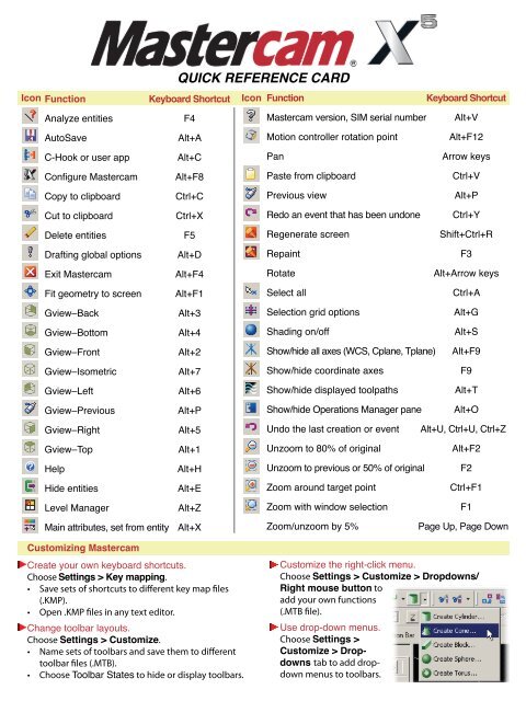
<strong>QUICK</strong> <strong>REFERENCE</strong> <strong>CARD</strong><br />
Icon Function<br />
Keyboard Shortcut Icon Function<br />
Keyboard Shortcut<br />
Analyze entities<br />
F4<br />
<strong>Mastercam</strong> version, SIM serial number Alt+V<br />
AutoSave<br />
Alt+A<br />
Motion controller rotation point<br />
Alt+F12<br />
C-Hook or user app Alt+C<br />
Pan<br />
Arrow keys<br />
Configure <strong>Mastercam</strong> Alt+F8<br />
Paste from clipboard<br />
Ctrl+V<br />
Copy to clipboard<br />
Ctrl+C<br />
Previous view<br />
Alt+P<br />
Cut to clipboard<br />
Ctrl+X<br />
Redo an event that has been undone Ctrl+Y<br />
Delete entities<br />
F5<br />
Regenerate screen<br />
Shift+Ctrl+R<br />
Drafting global options Alt+D<br />
Repaint<br />
F3<br />
Exit <strong>Mastercam</strong><br />
Alt+F4<br />
Rotate<br />
Alt+Arrow keys<br />
Fit geometry to screen Alt+F1<br />
Select all<br />
Ctrl+A<br />
Gview–Back<br />
Alt+3<br />
Selection grid options<br />
Alt+G<br />
Gview–Bottom<br />
Alt+4<br />
Shading on/off<br />
Alt+S<br />
Gview–Front<br />
Alt+2<br />
Show/hide all axes (WCS, Cplane, Tplane) Alt+F9<br />
Gview–Isometric<br />
Alt+7<br />
Show/hide coordinate axes<br />
F9<br />
Gview–Left<br />
Alt+6<br />
Show/hide displayed toolpaths<br />
Alt+T<br />
Gview–Previous<br />
Alt+P<br />
Show/hide Operations Manager pane Alt+O<br />
Gview–Right<br />
Alt+5<br />
Undo the last creation or event Alt+U, Ctrl+U, Ctrl+Z<br />
Gview–Top<br />
Alt+1<br />
Unzoom to 80% of original<br />
Alt+F2<br />
Help<br />
Alt+H<br />
Unzoom to previous or 50% of original F2<br />
Hide entities<br />
Alt+E<br />
Zoom around target point<br />
Ctrl+F1<br />
Level Manager<br />
Alt+Z<br />
Zoom with window selection<br />
F1<br />
Main attributes, set from entity Alt+X<br />
Zoom/unzoom by 5%<br />
Page Up, Page Down<br />
Customizing <strong>Mastercam</strong><br />
Create your own keyboard shortcuts.<br />
Choose Settings > Key mapping.<br />
• Save sets of shortcuts to different key map files<br />
(.KMP).<br />
• Open .KMP files in any text editor.<br />
Change toolbar layouts.<br />
Choose Settings > Customize.<br />
• Name sets of toolbars and save them to different<br />
toolbar files (.MTB).<br />
• Choose Toolbar States to hide or display toolbars.<br />
Customize the right-click menu.<br />
Choose Settings > Customize > Dropdowns/<br />
Right mouse button to<br />
add your own functions<br />
(.MTB file).<br />
Use drop-down menus.<br />
Choose Settings ><br />
Customize > Dropdowns<br />
tab to add dropdown<br />
menus to toolbars.
AutoCursor<br />
AutoCursor is automatically activated whenever you need to<br />
specify a location in the graphics window—for example, when<br />
creating geometry. Use AutoCursor to “snap” to geometry<br />
positions, to sketch points in space, or to type coordinate<br />
positions.<br />
To select a single<br />
location based<br />
on part geometry,<br />
choose the type<br />
of location from<br />
the drop-down list,<br />
and then click on<br />
the entity in the<br />
graphics window.<br />
FastPoint mode. Type the coordinate<br />
position and press [Enter].<br />
AutoCursor settings. Set the kinds of<br />
locations you want to snap to, and activate<br />
power key shortcuts for selection modes.<br />
AutoCursor Tips<br />
• Press [Spacebar] to enter<br />
FastPoint mode.<br />
• Hold [Ctrl] to temporarily<br />
release all snap settings<br />
and free-sketch point<br />
locations.<br />
• [Shift+click] a location to<br />
enter relative coordinates.<br />
• Right-click a selection<br />
option to lock it as the<br />
selection mode. Press [Esc]<br />
to unlock.<br />
• Double-click AutoCursor<br />
to undock it, or drag it<br />
anywhere in the window.<br />
If you close AutoCursor,<br />
<strong>Mastercam</strong> automatically<br />
displays it again when it is<br />
needed.<br />
AutoCursor Visual Cues<br />
AutoCursor uses the icons at left to tell you<br />
the type of location it is snapping to.<br />
Data Entry Shortcuts<br />
Built-in calculator<br />
Fields that take number values have a built-in calculator. Enter formulas<br />
or mathematical expressions; <strong>Mastercam</strong> will use the result.<br />
Automatic inch/metric conversion<br />
In inch mode, type a metric value followed by mm, cm, or m; <strong>Mastercam</strong><br />
will convert it. In metric mode, follow an inch measurement with in or ft to<br />
convert it.<br />
Reading values from geometry<br />
<strong>Mastercam</strong> can read dimensions, coordinate positions, and other<br />
values directly from geometry in the graphics window.<br />
• Right-click in the field or type ? to see the complete list of shortcuts.<br />
• Select a shortcut from the menu or type the hot key.<br />
• Type X, Y, Z, press [Tab] or [Enter], select point.<br />
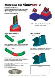
Dynamic Gnomon<br />
Displayed with certain functions<br />
(Dynamic Plane, Dynamic Xform)<br />
to orient entities or planes in the<br />
graphics window. Select specific<br />
positions on the gnomon to control<br />
function.<br />
1 Origin - Place the axis origin; translate XYZ/polar.<br />
2 First leg – Move/translate along the selected axis.<br />
3 Axis label (X, Y, Z) – X rotates about Y; Y and Z<br />
rotate about X.<br />
4 Second leg – Z rotates about Y; X and Y rotate<br />
about Z.<br />
5 Axis arrowhead – Align axis with existing geometry.
Selecting Geometry<br />
Use the General Selection ribbon bar to select or pre-select geometry.<br />
Selection masks.<br />
Set selection<br />
criteria: Only the<br />
entities that match,<br />
or All matching<br />
entities.<br />
Invert selection.<br />
Toggle<br />
between selected or<br />
unselected entities.<br />
Standard selection.<br />
Click an entity to select<br />
it or drag a selection window.<br />
[Shift+click] to select a chain.<br />
[Shift+click] again to end a<br />
partial chain. [Alt+click]<br />
to drag a selection vector.<br />
Solid selection. Activates<br />
solid selection mode. Select<br />
edges, faces, or solid bodies.<br />
Choose Select from back to select<br />
hidden edges or faces.<br />
Selecting multiple entities<br />
Chain. Select entities that form<br />
a chain.<br />
Window. Drag a rectangle to<br />
select all the entities inside it.<br />
Choose how boundary entities<br />
are included.<br />
Polygon. Draw an irregular shape and choose boundary options.<br />
Single. Select one entity at a time.<br />
Area selection. Select entities inside a closed boundary.<br />
Vector. Drag a line to select all entities that intersect it. Create a<br />
compound vector by clicking each corner; double-click when done.<br />
Use these tools in all selection modes:<br />
Select last. Reselect selections<br />
from the previous operation.<br />
Verify selection. When many<br />
entities are close together, highlight<br />
one after another. Click when the<br />
one you want is displayed.<br />
Cancel selection. Unselect all<br />
entities.<br />
End selection. Accept selection.<br />
Quick Masks<br />
Use Quick Masks (QM) to mask by entity type:<br />
• By default, QM functions are docked vertically to<br />
the right of the graphics window.<br />
• Left-click a QM function to toggle selection of all<br />
matching entities.<br />
• Right-click a QM function to allow selection of only<br />
matching entities. Right-click again to clear the list.<br />
QM Level<br />
QM Results<br />
QM Group<br />
QM Points QM Splines<br />
QM Lines QM Surface Curves<br />
QM Arcs QM Surfaces<br />
QM Drafting QM Solids<br />
Clear Masking QM Wireframe<br />
Invert<br />
QM Color<br />
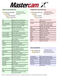
Chaining Geometry<br />
Enable dynamic start and end point selection.<br />
1 Chain wireframe geometry.<br />
2 Chain solid edges or faces.<br />
3 C-plane - Chain entities in the<br />
same plane as first chained entity.<br />
3D - Manually select when multiple<br />
entities share an endpoint.<br />
4 Select all continuous entities.<br />
5 Chain all entities inside window.<br />
6 Create a chain from a single entity.<br />
7 Chain all entities intersecting a<br />
vector (simple or compound).<br />
8 Chain a single point.<br />
9 Chain all entities inside a closed<br />
boundary.<br />
10 Draw polygon and chain all entities<br />
inside.<br />
11 Partial chaining. Select first and last<br />
entity to chain everything in between.<br />
12 Re-select chain from previous<br />
operation.<br />
13 End current chain and begin another.<br />
(Only used in certain modes.)<br />
14 Cancel selection, one chain at a time.<br />
15 Reverse chain direction.<br />
16 Set attributes for feature chaining.<br />
17 Chain features with specified attributes.<br />
18 Access advanced options and<br />
settings.<br />
1 2<br />
3<br />
4<br />
5<br />
6<br />
7<br />
12<br />
14<br />
16<br />
18<br />
8<br />
9<br />
10<br />
11<br />
13<br />
15<br />
17
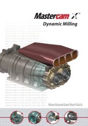
Backplot<br />
Use Backplot to examine individual tool moves.<br />
Click the button in the Toolpath Manager toolbar to backplot toolpaths.<br />
Play toolpath continuously, or stop/pause.<br />
Advance/rewind toolpath to next conditional<br />
stop.<br />
Advance/rewind toolpath to next step or move.<br />
Display entire toolpath at once.<br />
Display one move at a time.<br />
Drag to control playback speed<br />
Conditional stops pause at a predetermined step,<br />
coordinate position, tool change, or new operation.<br />
Slide the bar to advance the toolpath. Click a location to<br />
jump to that tool position. Click the slider to activate the<br />
mouse wheel for advance and rewind.<br />
• Colored areas show tool changes.<br />
• White bars indicate new operations.<br />
• Black tic marks indicate conditional stops.<br />
Hot keys<br />
S Step forward one move at a time.<br />
B Move back one move.<br />
R Toggle continuous run mode.<br />
P Go back to previous stop.<br />
N Advance to next stop.<br />
Toolpath information (on expanded dialog box)<br />
Click the<br />
the<br />
Click this tab to see information about the current toolpath<br />
move. See the type of move, coordinates, feed rate, and<br />
cutter compensation direction (for comp in control).<br />
Click this tab to see cycle time and path length for the<br />
toolpaths or segments currently backplotting.<br />
button to save the displayed toolpath as geometry. Click<br />
button to save the tool geometry. You are prompted to select a<br />
level, so the backplot entities will be separate from the part geometry.
Solids Manager<br />
The Solids Manager lists each solid body in the current part file. Expand the solid body to see the solid<br />
operations used to create it and the toolpath operations that machine it. Click an operation to select it.<br />
<strong>Mastercam</strong> highlights the feature in your part model.<br />
• Click Parameters to edit the operation settings.<br />
• Click Geometry to reselect the geometry.<br />
• Right-click a solid body to change its color or other<br />
attributes, check it for errors, or create a duplicate.<br />
• Solid operations that have been changed need to<br />
be regenerated.<br />
• When you create new solid operations, <strong>Mastercam</strong><br />
inserts them before the Stop Op icon.<br />
• Drag the Stop Op icon to prevent regenerating<br />
operations following it.<br />
• Regenerate regenerates all invalid operations.<br />
Art Manager<br />
The Art Manager lists all Art operations in the current part file. The Toolpath Manager lists Art toolpaths.
Operations Manager<br />
The Toolpath, Solids, and Art Managers share the Operations Manager pane on the left side of your<br />
window. Use them to review, edit, and manage toolpath, solid, and Art operations. Drag the right border to<br />
resize it, or click and drag the Operations Manager title bar to undock it anywhere on your desktop. Press<br />
[Alt+O] to hide it completely. Most functions will work on multiple operations if more than one is selected.<br />
Toolpath Manager<br />
The Toolpath Manager lists all toolpath operations in the current part file, grouped by machine definition.<br />
Select all operations.<br />
Select all invalid operations, which must be regenerated before<br />
posting.<br />
Regenerate all selected operations.<br />
Regenerate all invalid operations, whether or not they have been<br />
selected.<br />
Backplot selected operations, or click the icon in the operation list to<br />
backplot a single operation. Shows tool movements and positions.<br />
Verify the selected operations; shows the stock model.<br />
Post selected operations.<br />
Highfeed machining; optimize for machine dynamics and constant<br />
chip load.<br />
Start a new operations list; delete all operations and tools from the<br />
part file.<br />
Lock the operation from changes. Edit geometry but protect the<br />
toolpath from changing.<br />
Toggle selected toolpath display in the graphics window.<br />
Disable selected toolpath posting.<br />
Display toolpaths only when selected.<br />
Display only the geometry associated with the selected toolpaths.<br />
Working with geometry<br />
Click the Geometry icon to edit<br />
or reselect geometry for an<br />
operation, or drag it to another<br />
operation.<br />
Using the insertion point<br />
The insertion point shows where<br />
the next operation will be placed,<br />
which also determines the active<br />
machine and control definition.<br />
Move insertion point up<br />
or down.<br />
Position insertion point<br />
immediately after the currently<br />
selected operation.<br />
Automatically scroll Toolpath<br />
Manager so that the insertion<br />
point is visible.<br />
Toolpath uses surfaces or<br />
wireframe geometry.<br />
Toolpath uses solids or surfaces.<br />
Select drive/check surfaces,<br />
start points, and containment<br />
boundaries.<br />
Hot keys<br />
E Expand or collapse all operations.<br />
L Lock or unlock selected<br />
operations.<br />
P Toggle posting on selected<br />
operations.<br />
T Toggle toolpath display for<br />
selected operations.<br />
[Ctrl+X], [Ctrl+C] Cut or copy<br />
selected operations.<br />
[Ctrl+V] Paste operations at the<br />
insertion point.<br />
Right-click menu<br />
• Create new machine and<br />
toolpath groups.<br />
• Select operations that match<br />
criteria, such as the same tool.<br />
• Sort or renumber operations and<br />
tools.<br />
• Display options customize<br />
operations and properties.<br />
• Recalculate/update feeds and<br />
speeds.<br />
• Import/export library operations.<br />
• Post batch jobs.<br />
• Create job setup sheets.<br />
• Run collision/gouge check<br />
utilities.<br />
<strong>Mastercam</strong> is a registered trademark of CNC Software, Inc. © Copyright 2010 CNC Software, Inc. All rights reserved. September 2010 X5-Quick Reference Card