C5 Corvette IPC Diagnostic Display Mode
C5 Corvette IPC Diagnostic Display Mode
C5 Corvette IPC Diagnostic Display Mode

You also want an ePaper? Increase the reach of your titles
YUMPU automatically turns print PDFs into web optimized ePapers that Google loves.
<strong>C5</strong> <strong>Corvette</strong> <strong>IPC</strong> <strong>Diagnostic</strong> <strong>Display</strong> <strong>Mode</strong><br />
The <strong>IPC</strong> display, the 20-character, vacuum florescent screen above the steering column that says<br />
"<strong>Corvette</strong> by Chevrolet" every time you turn on the key is a powerful device.<br />
DIY Service Techs are going to be most interested in the LPG’s ability to show diagnostic trouble codes<br />
(DTC) for all the modules that transmit them.<br />
The "diagnostic display" mode is entered with the following Procedure: Page 8-500<br />
1) Turn on the ignition but don't start the engine.<br />
2) Press the "reset" button to turn off any warning messages<br />
3) Press and hold "options" and<br />
4) While holding "options", press "fuel" four times within a 10-Second period.<br />
Initially, the on-board diagnostics go into the "automatic" mode, which shows each module's DTCs in a<br />
pre-set sequence: (Page No. are for the GM Service Manual)<br />
10 PCNI Powertrain Control Module page 6-357 - 6-361<br />
28 TCS Traction Control system ABS on page 5-86<br />
?? RTD Real Time damping page 3-136<br />
40 BCM Body Control Module page 8-405 LTD Page 8-727<br />
60 [PC instrument Pane! Cluster page 8-508<br />
80 radio page 8-213<br />
99 FIVAC Heater Vent-Air Conditioning page 1-118<br />
A0 LDCM Left Door Control module page 8-904 to 8-951<br />
Al RDCM Right Door Control Module page 8-904 to 8-951<br />
AC SCM Seat Control module page 8-1064-8-1082<br />
B0 RFA Remote Function Actuation page 8-676<br />
For each module, all DTCs will be displayed. If none are present in a module, you will see "no more<br />
codes" on the ICP display.<br />
There are two kinds of DTCs, "Current" and "History," designated with a letter suffix, "C" or "H". A<br />
current code indicates that the malfunction is present in the system whose module is displaying data.<br />
A history code indicates a problem existed in that module sometime in the last 40 or 50 ignition cycles.<br />
When not accompanied by a current code of the same number, it is possible it's evidence of a previous<br />
problem. Now solved, that was not removed by clearing codes. More likely is that a history code<br />
indicates an intermittent malfunction.<br />
"Intermittent" are the most challenging DTCs. An intermittent may have happened only once, may<br />
have happened more than once but is inconsistent in its appearance or may be happening on a regular<br />
basis but not at the time the <strong>IPC</strong> is displaying codes. History codes can also be caused by a current<br />
malfunction in a system that is not Operating at the time DTCs are displayed. An example is the rear<br />
window defogger, which doesn't operate until the BCM detects engine rpm. For history codes set by a<br />
system that does not operate with the key on and engine off, a special diagnostic tool called a "scan<br />
tester is necessary to properly diagnose the malfunction.<br />
Once the <strong>IPC</strong> has displayed all 11 modules, the system goes into the manual mode, which allows<br />
selection of each module, using combinations of DIC buttons. The manual mode can also be entered at<br />
any time during the automatic sequence by pressing any button except "E/M". Once the <strong>IPC</strong> displays<br />
"manual diagnostics", you may select a particular module by pressing the options button to go forward<br />
or the "trip" button to go back. Once a system is selected and a DTC is displayed, if more than one are<br />
present; press "gages" To move forward or "fuel" to go back. To exit the diagnostic mode at any time,<br />
press E/M". If you want to erase or "clear" codes, press "reset". Clearing a code does not repair a<br />
problem. You are simply erasing the evidence of it in the module's memory.
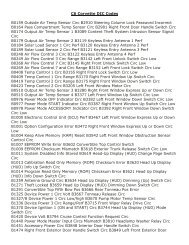
<strong>IPC</strong> <strong>Display</strong> Functions & Codes<br />
10 PCM Powertrain Control Module page 6-357 - 6-361 Domestic<br />
A=DTC set immediately and MIL is turned on<br />
B=MIL turned on after 2 consecutive drive trips<br />
C=After one failure and stored in History MIL not turned on<br />
P0101 Mass Air Flow (MAF) System performance -B<br />
P0102 Mass Air Flow (MAF) Sensor Circuit Low Frequency -A<br />
P0103 Mass Air Flow (MAF) Sensor Circuit High Frequency -A<br />
P0107 manifold Absolute Pressure (MAP) Sensor Circuit Low Voltage -A<br />
P0108 manifold Absolute Pressure (MAP) Sensor Circuit High Voltage -A<br />
P0112 Intake Air temperature (IAT) Sensor Circuit Low Voltage-B<br />
P0113 Intake Air temperature (IAT) Sensor Circuit High Voltage -B<br />
P0117 Engine Coolant Temperature (ECT) Sensor Low Voltage -A<br />
P0118 Engine Coolant Temperature (ECT) Sensor High Voltage -A<br />
P0118 Engine Coolant Temperature(ECT)Excessive Time to Closed Loop Fuel Control -B<br />
P0131 Heated Oxygen Sensor (HO2S) Circuit Low Voltage Bank 1 Sensor 1-A<br />
P0132 Heated Oxygen Sensor (HO25) Circuit High Voltage Bank 1 Sensor 1-A<br />
P0133 Heated Oxygen Sensor (HO25) Slow Response Bank 1 Sensor 1-B<br />
P0134 Heated Oxygen Sensor (HO25) Circuit Insufficient Activity Bank 1 Sensor 1-A<br />
P0135 Heated Oxygen Sensor (HO2S) Heater Circuit Bank 1 Sensor 1-B<br />
P0137 Heated Oxygen Sensor (HO2S) Circuit Low Voltage Bank 1 Sensor 2-B<br />
P0138 Heated Oxygen Sensor (HO2S) Circuit High Voltage Bank 1 Sensor 2-B<br />
P0140 Heated Oxygen Sensor (HO2S) Circuit Insufficient Activity Bank 1 Sensor 2-B<br />
P0141 Heated Oxygen Sensor (HO2S) Heater Circuit Bank 1 Sensor 2-B<br />
P0151 Heated Oxygen Sensor (HO2S) Circuit Low Voltage Bank 2 Sensor 1-A<br />
P0152 Heated Oxygen Sensor (HO2S) Circuit High Voltage Bank 2 Sensor 1-A<br />
P0153 Heated Oxygen Sensor (HO2S) Slow Response Bank 2 Sensor 1-A<br />
P0154 Heated Oxygen Sensor (HO2S) Circuit Insufficient Activity Bank 2 Sensor 1-A<br />
P0155 Heated Oxygen Sensor (HO2S) Heater Circuit Bank 2 Sensor 1-B<br />
P0157 Heated Oxygen Sensor (HO2S) Circuit Low Voltage Bank 2 Sensor 2-B<br />
P0158 Heated Oxygen Sensor (HO2S) Circuit High Voltage Bank 2 Sensor 2-B<br />
P0160 Heated Oxygen Sensor (HO2S) Circuit Insufficient Activity Bank 2 Sensor 2-B
P0161 Heated Oxygen Sensor (HO2S) Heater Circuit Bank 2 Sensor 2-B<br />
P0171 Fuel Trim System Lean bank 1-B<br />
P0172 Fuel Trim System Rich bank 1-B<br />
P0174 Fuel Trim System Lean bank 2-B<br />
P0175 Fuel Trim System Rich bank 2-B<br />
P0230 Fuel Pump Control Circuit -A<br />
P0300 Engine Misfire detected-B<br />
P0325 Knock Sensor (KS) System -B<br />
P0327 Knock Sensor (KS) Circuit Front -B<br />
P0332 Knock Sensor (KS) Circuit Rear -B<br />
P0335 CKP Sensor Circuit -A<br />
P0336 CKP Sensor Circuit Performance -A<br />
P0341 CMP Circuit Performance -B<br />
P0342 CMP Sensor Circuit Low Voltage -B<br />
P0343 CMP Sensor Circuit High Voltage -B<br />
P0351 Ignition Control #1 Circuit -A<br />
P0352 Ignition Control #2 Circuit -A<br />
P0353 Ignition Control #3 Circuit -A<br />
P0354 Ignition Control #4 Circuit -A<br />
P0355 Ignition Control #5 Circuit -A<br />
P0356 Ignition Control #6 Circuit -A<br />
P0357 Ignition Control #7 Circuit -A<br />
P0358 Ignition Control #8 Circuit -A<br />
P0410 AIR System-B<br />
P0412 AIR Solenoid relay Control Circuit-B<br />
P0418 AIR Pump Relay Control Circuit -B<br />
P0420 TWC System Low Efficiency Bank 1-A<br />
P0430 TWC System Low Efficiency Bank 2-A<br />
P0441 EVAP System No Flow During Purge -B<br />
P0461 Fuel Level Sensor 1 Circuit Performance -C<br />
P0462 Fuel Level Sensor 1 Circuit Low Voltage -C<br />
P0463 Fuel Level Sensor 1 Circuit High Voltage -C
P0480 FC Relay 1 Control Circuit -B<br />
P0481 FC Relay 2 and 3 Control Circuit -B<br />
P0500 VSS Circuit (M/T) -B<br />
P0506 Idle Speed Low -B<br />
P0507 Idle Speed High -B<br />
P0522 Engine Oil Pressure Sensor Circuit Low Voltage (w/message) -C<br />
P0523 Engine Oil Pressure Sensor Circuit High Voltage (w/message) -C<br />
P0530 A/C Refrigerant Pressure Sensor Circuit - C<br />
P0562 System Voltage Low -C<br />
P0563 System Voltage High -C<br />
P0567 Cruise Resume Circuit -C<br />
P0568 Cruise Set Circuit -C<br />
P0571 Cruise Brake Switch Circuit (M/T) -C<br />
P0601 PCM Memory -A<br />
P0602 PCM Not Programmed -A<br />
P0604 PCM RAM Performance -A<br />
P0606 PCM Internal Communication Interrupted -A<br />
P0608 VSS Output Circuit -C<br />
P0650 MIL Control Circuit-B (No MIL)<br />
P0654 Engine Speed Output Circuit -C<br />
P0704 Clutch Switch Circuit(M/T) -B<br />
P0705 Transmission range Switch Circuit (A/T) -C<br />
P0706 Transmission Range Switch Performance (A/T) -C<br />
P0801 Reverse Inhibit Solenoid Control Circuit (M/T) -C<br />
P0803 1-4 Upshift Solenoid Control Circuit (M/T) -B<br />
P0804 1-4 Upshift lamp Control Circuit (M/T) -C<br />
P1111 Intake Air temperature (IAT) Sensor Circuit Intermittent High Voltage -C<br />
P1112 Intake Air temperature (IAT) Sensor Circuit Intermittent Low Voltage -C<br />
P1114 ECT Sensor Circuit Intermittent Low Voltage -C<br />
P1115 ECT Sensor Circuit Intermittent High Voltage -C<br />
P1120 TP sensor 1 Circuit -A<br />
P1125 APP System -A<br />
P1133 Heated Oxygen Sensor (HO2S) Insufficient Switching Bank 1 Sensor 1-8
P1134 Heated Oxygen Sensor (HO2S) Transition Time ratio Bank 1 Sensor 1-B<br />
P1153 Heated Oxygen Sensor (HO2S) Insufficient Switching Bank2 Sensor 1-B<br />
P1154 Heated Oxygen Sensor (HO2S) Transition Time ratio Bank 2 Sensor 1-B<br />
P1220 TP sensor 2 Circuit -A<br />
P1221 TP Sensors 1,2 Performance -A<br />
P1258 Engine Coolant Over Temperature-Fuel disabled -A<br />
P1275 APP Sensor 1 Circuit-C<br />
P1276 APP Sensor 1 Circuit Performance -C<br />
P1280 APP Sensor 2 Circuit -C<br />
P1281 APP Sensor 2 Circuit Performance -C<br />
P1285 APP Sensor 3 Circuit -C<br />
P1286 APP Sensor 3 Circuit Performance -C<br />
P1380 EB(T)CM DTC Detected- rough road data Unusable -C<br />
P1381 Misfire Detected - No EB(T)CM/PCM Serial data -V<br />
P1415 AIR System bank 1-B<br />
P1416 AIR System bank 2-B<br />
P1431 Fuel Level Sensor 2 Circuit Performance -C<br />
P1432 Fuel Level Sensor 2 Low Voltage -C<br />
P1433 Fuel Level Sensor 2 High Voltage -C<br />
P1441 Evaporative Emissions (EVAP) System Flow During Non-Purge-B<br />
P1S14TAC System MAF Performance -A<br />
P1515 Command vs Actual Throttle Position performance (PCM Module) -A<br />
P1516 Command vs Actual Throttle Position performance (TAC Module) -A<br />
P1S17TAC Module Processor-A<br />
P1518 PCM to TAC Module Serial Data Circuit -<br />
P1539 A/C Clutch Status Circuit High Voltage -C<br />
P1545 A/C Clutch Relay Control Circuit -C<br />
P1546 A/C Clutch Status Circuit Low Voltage -C<br />
P1571 ASR Desired Torque -C<br />
P1574 Stop lamp Control Circuit -C<br />
P1575 Extended Travel Brake Switch Circuit High Voltage -C<br />
P1626 Theft Deterrent System Fuel enable Circuit -C
P1630 Theft Deterrent System PCM in Learn <strong>Mode</strong> -C<br />
P1631 Theft Deterrent System password Incorrect-C<br />
P16355 volt Reference #1 Circuit-B<br />
P16395 volt Reference #2 Circuit-B<br />
P1644 Delivered Torque Output Circuit -C<br />
P1652 Powetrain Induced Chassis Pitch Output Circuit –<br />
28 TCS Traction Control system ABS on page 5-86<br />
C1214 Sol Valve relay Contact or coil CKT Open<br />
C1217 BPMV Pump Motor Relay Contact CKT Open<br />
C1221 LF Wheel Speed Sensor Input Signal is 0<br />
C1222 RF Wheel Speed Sensor Input Signal is 0<br />
C1223 LR Wheel Speed Sensor Input Signal is 0<br />
C1224 RR Wheel Speed Sensor Input Signal is 0<br />
C1225 RF Excessive Wheel Speed Variation<br />
C1226 LF Excessive Wheel Speed Variation<br />
C1227 LR Excessive Wheel Speed Variation<br />
C1228 RR Excessive Wheel Speed Variation<br />
C1232 LF Wheel Speed Circuit Open or Shorted<br />
C1233 RF Wheel Speed Circuit Open or Shorted<br />
C1234 LR Wheel Speed Circuit Open or Shorted<br />
C1235 RR Wheel Speed Circuit Open or Shorted<br />
C1236 Low System Supply Voltage<br />
C1237 High System Supply Voltage<br />
C1241 Magna Steer Circuit Malfunction Refer to variable effort steering on Steering<br />
C1242 BPMV Pump Motor Ground Circuit Open<br />
C1243 BPMV Pump Motor Stalled<br />
C1255 EBTCM Internal malfunction<br />
CEBCM Internal Malfunction<br />
C1261 LF Inlet Valve Solenoid Malfunction<br />
C1262 LF Outlet Valve Solenoid Malfunction<br />
C1263 RF Inlet Valve Solenoid Malfunction<br />
C1264 RF Outlet Valve Solenoid Malfunction<br />
C1265 LR Inlet Valve Solenoid Malfunction
C1266 LR Outlet Valve Solenoid Malfunction<br />
C1267 BR Inlet Valve Solenoid Malfunction<br />
C1268 BR Outlet Valve Solenoid Malfunction<br />
C1273 RF TCS Master Cyl Isolation Valve malfunction<br />
C1274 RFTCS Prime Valve malfunction<br />
C1276 Delivered Torque Signal CKT malfunction<br />
C1277 Requested Torque Signal CKT Malfunction<br />
C1278 TCS Temporarily Inhibited by PCM<br />
C1281 Steering Sensor Uncorrelated Malfunction<br />
C1286 Steering Sensor Bias Malfunction<br />
C1287 Steering Sensor rate malfunction<br />
C1291 Open brake lamp Sw Contacts During Deccel<br />
C1293 DTC C1291/C1292 Set Curnt/Prev lgn Cycle<br />
C1294 Brake Lamp Switch Circuit Always Active<br />
C1295 Brake Lamp Switch Circuit Open<br />
U1016 Loss of Communications with PCM<br />
U1255 Generic Loss Communications<br />
U1300 Class 2 Circuit Shorted to ground Refer to Data Link Connector System Check in Wiring System<br />
U1301 Class 2 Circuit Shorted to battery Refer to Data Link Connector System Check in Wiring System<br />
RTD Real Time Damping page 3-136<br />
C1650 ESC Module Malfunction<br />
C1658 EEPROM calibration Malfunction<br />
C1710 LF Shock Absorber Solenoid (Short to Voltage)<br />
C1711 LF Shock Absorber Solenoid (Short to GND)<br />
C1712 LF Shock Absorber Solenoid (Open Circuit)<br />
C1715 RF Shock Absorber Solenoid (Short to Voltage)<br />
C1716 RF Shock Absorber Solenoid (Short to GND)<br />
C1717 RF Shock Absorber Solenoid (Open Circuit)<br />
C1720 LR Shock Absorber Solenoid (Short to Voltage)<br />
C1721 LR Shock Absorber Solenoid (Short to GND)<br />
C1722 LR Shock Absorber Solenoid (Open Circuit)<br />
C1725 RR Shock Absorber Solenoid (Short to Voltage)
C1726 RR Shock Absorber Solenoid (Short to GND)<br />
C1727 RR Shock Absorber Solenoid (Open Circuit)<br />
C1743 Loss of Vehicle Speed Signal<br />
C1760 LF Position Sensor (Out of range)<br />
C1761 RF Position Sensor (Out of range)<br />
C1762 LR Position Sensor (Out of range)<br />
C1763 RR Position Sensor (Out of range)<br />
C1768 Position Sensor Supply malfunction (Overcurrent)<br />
C1780 Loss of Steering Position Signal<br />
C1786 RTD Control Relay Malfunction<br />
C1787 RTD Control Relay Circuit (Open or Short to GND)<br />
C1788 RTD Control relay Circuit (Short to Voltage)<br />
C1790 Ride control switch (out of range)<br />
C1791 Ride control switch (contact malfunction)<br />
40 BCM Body Control Module page 8-405 UTD Page 8-727<br />
B0432 Rear Defogger Relay Circuit<br />
B0433 Rear Defogger Relay Circuit<br />
B0502 RH DRL Relay Circuit<br />
B0503 RH DRL Relay Circuit<br />
B0507 LH DRL Relay Circuit<br />
B0508 LH DRL Relay Circuit<br />
B0605 BCM Internal Memory Function<br />
B0844 BCM Temporarily Inhibit ABS<br />
B2403 Front Fog lamp Switch Circuit<br />
B2408 Rear Fog Lamp Switch Circuit<br />
B2482 Backup Lamp Relay Circuit<br />
B2483 Backup Lamp Relay Circuit<br />
B2527 Horn Relay Circuit<br />
B2528 Horn Relay Circuit<br />
B2573 Hatch Release Switch Circuit (Short to Voltage)<br />
B2578 RF Turn Signal Monitor Circuit (Short to Voltage)<br />
B2583 LF Turn Signal Monitor Circuit (Short to Voltage)<br />
B2587 Column Lock/Unlock Drive (A)
B2588 Column Lock/Unlock Drive (A)<br />
B2592 Column Lock/Unlock Drive (B)<br />
B2583 Column Lock/Unlock Drive (8)<br />
B2597 Traction Control System Switch Circuit<br />
B2721 PASS-Key Detection Circuit<br />
B2722 PASS-Key Detection Circuit<br />
B2723 PASS-Key Detection Circuit<br />
B2735 PASS-Key Programming <strong>Mode</strong> Active<br />
U1016 Loss of Communication with PCM<br />
U1096 Loss of Communications with <strong>IPC</strong><br />
U1255 Serial Data Line malfunction<br />
60 <strong>IPC</strong> Instrument Panel Cluster page 3-508<br />
B0516 Speedometer Signal Circuit Malfunction<br />
B0521 Tachometer Signal Circuit Malfunction<br />
B1512 DIC Switch 1 Signal Short to GND "FUEL'<br />
B1517 DIC Switch 2 Signal Short to GND "GAGES"<br />
B1522 DIC Switch 3Signal Short to GND "TRIP"<br />
B1527 DIC Switch 4 Signal Short to GND "OPTIONS"<br />
B1532 DIC Switch 5 Signal Short to GND "E/M"<br />
B1537 DIC Switch 6 Signal Short to GND "RESET"<br />
B1542 Oil Temperature Circuit Short to GND<br />
B1543 Oil Temperature Circuit Open<br />
U1016 Loss of Communications with PCM<br />
U1040 Loss of Communication with TCS<br />
U1056 Loss of Communications with RTD<br />
U1064 Lose of Communications with DCM<br />
U1128 Loss of Communications with radio<br />
U1153 Loss of Communications with HVAC<br />
U1160 Loss of Communications with LDCM<br />
U1161 Loss of Communications with DCM<br />
U1166 Loss of Communications with SCM<br />
U1176 Loss of Communications with RFA
U1255 Serial Data Line malfunction<br />
80 radio none found page 8-213<br />
99 HVAC Heater Vent-Air Conditioning page 1-118<br />
B0332 Outside Air Temp sensor Short to GND<br />
B0333 Outside Air temp sensor open<br />
B0337 Inside Air temp Sensor Short to GND<br />
B0338 Inside Air temp sensor open<br />
B0348 Sunload temperature sensor open<br />
B0361 Left Actuator Feedback short to GND<br />
B0363 Left Actuator Feedback Open<br />
B0365 Right Actuator Feedback short to GND<br />
B0367 Right Actuator Feedback Open<br />
B0441 Left Actuator Out of Range<br />
B0446 Right Actuator Out of Range<br />
B1016 Loss of Communications with PCM (No State of Health Message)<br />
U1064 Loss of Communications with DCM (No State of Health Message)<br />
U1096 Loss of Communications with <strong>IPC</strong> (No State of Health Message)<br />
U1255 Serial Data Line malfunction<br />
A0 LDCM Left Door Control module page 8-904 to 8-951<br />
B2202 Left Window Up Switch Fault DCM-LEFT<br />
B2204 Left Window Down Switch Fault DCM-LEFT<br />
B2206 Right Window Up Switch Fault DCM LEFT<br />
B2208 Right Window Down Switch Fault DCM-L<br />
B2222 LT Mirror Select Switch Fault DCM-LEFT<br />
B2224 RT Mirror Select Switch Fault DCM-LEFT<br />
B2226 Mirror Right Switch Fault DCM-LEFT<br />
B2228 Mirror Left Switch Fault DCM-LEFT<br />
B2232 Mirror Up Switch Fault DCM-LEFT<br />
B2234 Mirror Down Switch Fault DCM-LEFT<br />
B2236 Left Door lock Switch Fault DCM-LEFT<br />
B2238 Left Door unlock Switch Fault DCM-LEFT<br />
B2242 Memory 1 Switch Fault DCM-LEFT<br />
B2244 Memory 2 Switch Fault DCM-LEFT
B2252 Key Cylinder Switch Fault DCM-LEFT<br />
B2262 Horizontal Position Sensor Fit DCM-L<br />
B2264 Vertical Position Sensor Fault DCM-L<br />
B2272 Left Mirror Motor Fault DCM-L<br />
B2274 Window Motor Fault DCM-LEFT<br />
B2276 Door Lock Motor/Mirror Heater Fit DCM-L<br />
B2282 Battery #1 Fault DCM-LEFT<br />
B2284 Battery #2 Fault DCM-LEFT<br />
B2286 +5v Reference Fault DCM-LEFT<br />
A1 RDCM Right Door Control Module a page 8-904 to 8-051<br />
B2203 Right Window Up Switch Fault DCM RIGHT<br />
B2205 Right Window Down Switch Fault DCM-R<br />
B2237 Right Door Lock Switch Fault DCM-RIGHT<br />
B2239 Right Door Un-Lock Switch Fault DCM-RIGHT<br />
B2253 Key Cylinder Switch Fault DCM-RIGHT<br />
B2263 Horizontal Position Sensor Fit DCM-R<br />
B2265 Horizontal Position Sensor Fault DCM-R<br />
B2273 Right Mirror Motor Fault DCM-Right<br />
B2275 Window Motor Fault DCM-Right<br />
B2277 Door Lock Motor/Mirror Heater Fit DCM-R<br />
B2283 Battery #1 Fault DCM-RIGHT<br />
B2285 Battery #2 Fault DCM-RIGHT<br />
B2287 +5v Reference Fault DCM-RIGHT<br />
AC SCM Seat Control module page 8-1064 8-1082<br />
B0846 Battery 2 Out of range<br />
B0851 Battery 1 out of range<br />
B2002 Fore/Aft Seat motor Open or Short to GND<br />
B2007 Front Vert. Seat motor Open or Shorted<br />
B2012 Rear Vert. Seat motor Open or Shorted<br />
B2172 Seat Front Up Switch Shorted to GND<br />
B2177 Seat Front Down Switch Shorted to GND<br />
B2182 Seat Rear Up Switch Shorted to GND
B2187 Seat Rear Down Switch Shorted to GND<br />
B2192 Seat Forward Switch Shorted to GND<br />
B2197 Seat Reverse Switch Shorted to GND<br />
B2605 Seat Front Vert Position Sensor Failure<br />
B2606 Seat Rear Vert. Position Sensor Failure<br />
B2607 Seat Horizontal Position Sensor Failure<br />
B0 RFA Remote Function Actuation page 8-676<br />
B0605 Receiver Internal memory malfunction -RFA<br />
B2805 No Transmitters Programmed -RFA<br />
C21 00 Left Front TPM Sensor Malfunction -TPM<br />
C2105 Right Front TPM Sensor Malfunction -TPM<br />
C2110 Right Rear TPM Sensor Malfunction -TPM<br />
C2115 Left Rear TPM Sensor Malfunction -TPM<br />
C2120 TPM System malfunction (No Sensors Received -TPM<br />
C2121 TPM System Programming malfunction (No Sensors Programmed)-TPM<br />
U1000 Loss of Communication Undetermined -RFA<br />
U1016 Loss Of Communication with PCM (No SOH Message Received -RFA<br />
U1064 Loss Of Communication with DCM (No SOH Message Received -RFA<br />
U1096 Loss Of Communication with <strong>IPC</strong> (No SOH Message Received -RFA<br />
U1255 Serial Data Line Malfunction -RFA