View LeCroy WAVERUNNER 6200A Specifications - TekNet ...
View LeCroy WAVERUNNER 6200A Specifications - TekNet ...
View LeCroy WAVERUNNER 6200A Specifications - TekNet ...

Create successful ePaper yourself
Turn your PDF publications into a flip-book with our unique Google optimized e-Paper software.
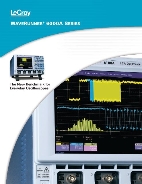
<strong>WAVERUNNER</strong> ® 6000A SERIES<br />
The New Benchmark for<br />
Everyday Oscilloscopes
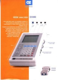
The WaveRunner 6000A Series<br />
The Everyday Bench Oscilloscope<br />
The WaveRunner ® 6000A Series is the best oscilloscope for<br />
everyday signal testing. Its remarkable functionality includes<br />
the following capabilities:<br />
– acquisition technology that delivers measurements you can trust<br />
– an efficient interface that feels just right to the busy engineer<br />
– uncommon capabilities—right out of the box<br />
– a platform for building on even more functionality<br />
A Rich Feature Set is Standard<br />
The WaveRunner 6000A Series is<br />
an everyday bench scope with true<br />
“lab instrument” capabilities. This<br />
series offers:<br />
• Bandwidths from 350 MHz to 2 GHz<br />
• Sample rates of 2.5 to 10 GS/s<br />
• Standard memory of 4 Mpts/Ch<br />
• All channels expandable to 12 Mpts<br />
• Up to 24 Mpts when interleaved<br />
Most importantly, these features are<br />
delivered at a price far below other<br />
oscilloscopes in this class.<br />
Outstanding Signal Fidelity<br />
The WaveRunner 6000A Series<br />
is powered by the same SiGe<br />
chipset that is used in <strong>LeCroy</strong>’s<br />
higher bandwidth WaveMaster<br />
oscilloscopes.<br />
• High sample rate captures<br />
high frequency transients<br />
and sharp edges<br />
• Very low residual jitter (2 ps typical)<br />
• Includes ultra-stable clock (±5 ppm)<br />
This outstanding performance gives<br />
you timing resolution that rivals<br />
oscilloscopes that cost twice as much.<br />
Windows ® XP<br />
Operating System<br />
The open Windows XP operating<br />
system allows you to install Windows<br />
application software to analyze waveform<br />
data directly in the oscilloscope,<br />
eliminating the need for processing<br />
in another PC.<br />
2
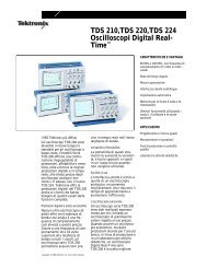
5 GS/s on Each Channel—<br />
See Details Others Miss<br />
The WaveRunner 6000A is a true<br />
4 channel instrument—you can<br />
sample at a full 5 GS/s on each<br />
channel. Other oscilloscopes can only<br />
use a single channel at 5 GS/s or 1/4<br />
that rate when using all four channels.<br />
WaveRunner 6000A offers more than<br />
Nyquist sample rate on each channel.<br />
With a true 5 GS/s on each channel, this<br />
300 MHz square wave (checking a timing<br />
delay problem between multiple clock<br />
signals) is displayed accurately.<br />
Other oscilloscopes are limited to 1.25 GS/s<br />
on each channel and display the same<br />
measurement as a less than informative<br />
sinusoidal signal.<br />
SMART Trigger Makes the<br />
Most of Your Long Memory<br />
The WaveRunner 6000A SMART Trigger<br />
provides the flexibility to quickly trigger<br />
and locate the specific signal characteristic<br />
or pattern you want. Trigger on<br />
abnormal signals at the touch of a button.<br />
• Exclusion/inclusion feature triggers<br />
on signals outside, or within, a<br />
specific range of pulse widths.<br />
• Selecting multiple threshold levels<br />
and pulse widths quickly catches the<br />
waveform for viewing and measuring.<br />
• Memory retains thousands of<br />
acquired events for viewing at<br />
your leisure.<br />
• Replay signal history, scan, and<br />
search from sweep to sweep.<br />
3
The WaveRunner 6000A Series<br />
An Outstanding Scope Experience<br />
4<br />
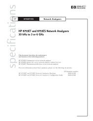
The WaveRunner 6000A oscilloscope<br />
is designed to be a custom fit to your<br />
working style. Hundreds of oscilloscope<br />
users helped us meet this goal by<br />
contributing their ideas to the<br />
uniquely efficient interface.<br />
1. Bright Display<br />
All WaveRunner 6000A Series oscilloscopes<br />
include a crisp and bright SVGA<br />
screen with 800 x 600 pixels for superior<br />
resolution. It’s the best resolution<br />
available for this class of scope.<br />
2. One-touch Efficiency<br />
The descriptor labels show the<br />
oscilloscope settings and status.<br />
Touch the screen once to open a<br />
setup dialog and change settings.<br />
Quickly measure a signal’s timing<br />
characteristics. Touch “Measure” and<br />
“Horizontal” to see multiple common<br />
timing parameters. Math, histograms,<br />
statistics, and other analysis tools<br />
are all within two touches.<br />
3. Dedicated Vertical Controls<br />
Each channel has its own volts per<br />
division (V/div) control knob. You can<br />
control any channel by turning the<br />
knob—eliminating the need to<br />
multiplex a single V/div control across<br />
all four channels.<br />
4. Intensity Modulated Display<br />
Display intensity can be adjusted<br />
from 0–100% to enable a better<br />
view of underlying glitches, runts,<br />
or signal modulation in long record<br />
captures. The perfect accompaniment<br />
to the WaveRunner 6000A oscilloscope’s<br />
long memory.<br />
1<br />
4<br />
2
PP007 Passive Probe<br />
Only 2.5 mm in diameter<br />
with low circuit loading and<br />
a flat impulse response,<br />
this probe is the ideal fit for<br />
general-purpose applications.<br />
7<br />
3<br />
5 6<br />
8<br />
5. Cursor Knobs<br />
Need a quick measurement? Just<br />
turn the cursor knob to bring up a pair<br />
of vertical cursors to measure timing<br />
relationships and quickly characterize<br />
the waveform.<br />
6. Zoom Control Knobs<br />
Need a closer look at your signal?<br />
Push the QuickZoom button. Four<br />
dedicated knobs (zoom and offset in<br />
horizontal and vertical directions) make<br />
it easy to navigate any trace—from<br />
broad relationships to minute details.<br />
7. “Push” Knobs<br />
WaveRunner rotating knobs control<br />
functions, but pushing them invokes<br />
further functionality. Push the trigger<br />
level; the scope selects the correct<br />
setting for a stable display. Push the<br />
offset button; your scope instantly<br />
zeroes the offset, restoring the<br />
waveform clearly in the middle of<br />
the screen. Another push restores<br />
the offset.<br />
8. Handy, Front Accessible<br />
USB Port<br />
Use a memory stick to transfer your<br />
captured waveforms, or take your setup<br />
from scope to scope to automatically<br />
load your configuration. In addition,<br />
with one USB port on the front panel<br />
and four more on the back, you can<br />
connect a variety of plug-n-play<br />
peripheral and memory devices.<br />
5
LabNotebook <br />
An In-Scope Solution for Documenting Results<br />
WaveRunner lets you focus on understanding your signal rather<br />
than setting up your oscilloscope.The productivity improvement<br />
is dramatic and immediate. Here’s a prime example of how<br />
thoroughly WaveRunner fits your everyday process.<br />
<strong>LeCroy</strong> Introduces a Complete<br />
In-scope Solution—Standard<br />
on most <strong>LeCroy</strong> Oscilloscopes<br />
Now you can efficiently create<br />
complete and detailed waveform<br />
reports directly in the oscilloscope.<br />
An all-in-one solution for annotating<br />
and sharing information, LabNotebook<br />
simplifies results recording and report<br />
generation by eliminating the multi-step<br />
processes that often involve several<br />
pieces of equipment.<br />
LabNotebook enables you to focus<br />
on results rather than the process, so<br />
you can now:<br />
• Save all displayed waveforms<br />
• Save the relevant setups with the<br />
saved waveform<br />
• Add freehand notes with a stylus<br />
or as text<br />
• Convert the complete report to pdf,<br />
rtf, or html<br />
• Print or e-mail reports<br />
Create Notes with the<br />
Screen Capture<br />
By pressing Hard Copy, you can<br />
annotate waveforms as you<br />
capture them. Once the notes<br />
are finished, they can be readily<br />
saved as a report and e-mailed<br />
directly from the oscilloscope.<br />
Flashback Function<br />
You can employ the Flashback Function<br />
to recall the state of the oscilloscope,<br />
including saved waveforms and setup.<br />
Additional measurements are easily<br />
made using the keyword filter to find<br />
the correct notebook entry for recall.<br />
6
From Everyday Testing<br />
to Robust Analysis<br />
It’s the perfect end-to-end solution: a bench top oscilloscope<br />
that can handle everyday signal measurements easily and<br />
efficiently, but can expand to perform more sophisticated<br />
WaveShape Analysis when needed. Yet it’s priced far below<br />
other scopes that are not nearly as versatile and fully featured.<br />
Expanded Analysis<br />
The XMATH Advanced Math software<br />
package provides more than 30 math<br />
functions and 40 parameter measurements<br />
including:<br />
• Parameter math<br />
• Tracking measurements<br />
• Expanded FFT (up to 24 Mpts)<br />
• Expanded histogramming<br />
• Trending of up to one million events<br />
XMATH has a graphical interface<br />
that lets you connect input source,<br />
measurement, and display icons for<br />
surprisingly simple advanced analysis.<br />
Custom Analysis<br />
The XDEV Advanced Customization<br />
software package allows you to create<br />
your own scripts for measurement<br />
parameters or math functions, using<br />
third-party software packages such as<br />
Excel, MATLAB, and Mathcad.<br />
XDEV seamlessly integrates your the oscilloscope’s interface. This<br />
custom measurements directly into package utilizes the power and<br />
the oscilloscope’s data path, eliminating efficiency of customization to<br />
the need to run separate programs. You enable faster analysis and solutions<br />
can also use XDEV to customize for your specific tasks.<br />
Software Option Packages<br />
General Purpose<br />
Master Analysis Software Package (Includes JTA2, XMATH and XDEV) WR6-XMAP<br />
Advanced Math Software Package<br />
WR6-XMATH<br />
Customization Software Package<br />
WR6-XDEV<br />
Value Analysis Software Package (Includes XWAV and JTA2)<br />
WR6-XVAP<br />
Intermediate Math Software Package<br />
WR6-XWAV<br />
Processing Web Editor Software Package for Functions and Parameters WR6-XWEB<br />
Application Specific<br />
Jitter and Timing Analysis Software Package<br />
WR6-JTA2<br />
PowerMeasure Analysis Software Package<br />
WR6-PMA2<br />
Digital Filter Software Package<br />
WR6-DFP2<br />
EMC Pulse Parameters Software Package<br />
WR6-EMC*<br />
Disk Drive Measurement Software Package<br />
WR6-DDM2<br />
Ethernet Test Software Package (WaveRunner <strong>6200A</strong> Only)<br />
WR6-ENET<br />
USB 2.0 Compliance Test Software Package (WaveRunner <strong>6200A</strong> Only) WR6-USB2<br />
Serial Data Mask Software Package<br />
WR6-SDM†<br />
Software and Hardware Option Packages<br />
32 Digital Channel Oscilloscope Mixed Signal Option MS-32 ‡<br />
CANbus TDM Trigger, Decode and Measure/Graph Testing Option CANbus TDM<br />
CANbus TD Trigger and Decode Testing Option<br />
CANbus TD<br />
*WR6-EMC is compatible with all WaveRunner 6000A oscilloscopes except the WR6030A model.<br />
† WR<strong>6200A</strong> oscilloscope required for full mask testing capability; lower bandwidth models will have<br />
reduced capabilities.<br />
‡ MS-32 is compatible only with WR6000A 4-channel oscilloscopes.<br />
7
Expandability Ensures an<br />
Excellent Return on Investment<br />
8<br />
Mixed Signal Testing<br />
Oscilloscope Option (MS-32)*<br />
Add 32 digital channels to a 4-channel<br />
oscilloscope for 4 analog + 32 digital<br />
testing capability, with a simple<br />
oscilloscope setup and user interface.<br />
Each digital channel has 1 Mpts/Ch<br />
(32 Mpts total!) to capture all of your<br />
signal information for efficient debug<br />
and analysis. 32 digital channels is<br />
ideal for the most efficient testing of<br />
16-bit embedded controllers where<br />
all 16 ADDR and DATA lines can be<br />
viewed simultaneously.<br />
*MS-32 is compatible only with WR6000A<br />
4-channel oscilloscopes.<br />
CANbus Trigger, Decode,<br />
and Measure/Graph Testing<br />
Options (CANbus TDM,<br />
CANbus TD)<br />
Flexibly trigger on CAN bus messages.<br />
Decode and display hexadecimal data<br />
values next to the CAN signal on the<br />
screen. Measure and statistically<br />
analyze timing and other data. Graph<br />
system performance. Easily correlate<br />
electrical problems to CAN bus<br />
messages or error frame data.<br />
Jitter and Timing Analysis<br />
Software Package (JTA2)<br />
Find modulation effects and intermittent<br />
signal jitter to track timing changes,<br />
and to debug in the time, frequency,<br />
and statistical domains. <strong>View</strong>s like Jitter<br />
Track and Jitter Histogram let you see<br />
system variability in ways that you have<br />
never imagined.<br />
Digital Filter Software Package<br />
(DFP2)<br />
DFP2 lets you add any of a set of<br />
linear-phase Finite Impulse Response<br />
(FIR) filters. It enhances your ability to<br />
examine important signal components<br />
by filtering out undesired spectral<br />
components such as noise. Use the<br />
standard filters or create your own.<br />
Electromagnetic<br />
Compatibility Software<br />
Package (EMC)*<br />
The EMC software package<br />
adds flexibility to the rise time,<br />
fall time, and width parameters<br />
that are necessary to accurately<br />
measure ESD pulses, EFT bursts,<br />
surges and transients that are<br />
common in EMC testing. The<br />
WaveRunner 6000A provides<br />
easy access to parameter statistics<br />
and, with the EMC package,<br />
allows histogramming up to 2 billion<br />
events, parameter math, and<br />
measurement filtering.<br />
*WR6-EMC is compatible with all WaveRunner 6000A<br />
oscilloscopes except the WR6030A model.<br />
Disk Drive Measurement<br />
Software Package (DDM2)<br />
The Disk Drive Measurement Package<br />
(DDM2) adds dozens of new disk drive<br />
measurements. DDM2, combined<br />
with WaveRunner 6000A’s sequence<br />
triggering and SMART Triggers, offers<br />
the perfect solution for failure analysis<br />
when testing disk drives.<br />
PowerMeasure Analysis<br />
Software Package (PMA2)<br />
The PMA2 package automates and<br />
enhances your ability to analyze<br />
power conversion devices and<br />
circuits. Optional accessories, such<br />
as differential amplifiers, differential<br />
probes, current probes, and deskew<br />
fixtures complete the solution.<br />
USB 2.0 Compliance Test<br />
Software Package (USB2)<br />
(WaveRunner <strong>6200A</strong> Only)<br />
USB2 provides a complete acquisition<br />
and analysis system for USB 2.0<br />
devices, hosts, and hubs, as specified<br />
in the USB-IF USB 2.0 Electrical Test<br />
Specification, version 1.0.<br />
Ethernet Test Software<br />
Package (ENET)<br />
(WaveRunner <strong>6200A</strong> Only)<br />
Conduct complete electrical testing<br />
for 1000Base-T, 100Base-T, and<br />
10Base-T Ethernet standards. Jitter<br />
and pulse mask tests are performed<br />
with automatic waveform alignment,<br />
and all test results feature pass/fail<br />
indicators corresponding to the<br />
IEEE 802.3-2000 and ANSI X3.263<br />
standards being tested.<br />
Serial Data Mask Software<br />
Package (SDM)*<br />
The SDM toolset harnesses the<br />
WaveRunner 6000A Series ocilloscope’s<br />
long memory and low jitter to deliver<br />
outstanding serial bus characterization.<br />
Choose from a comprehensive list<br />
of standard eye pattern masks, or<br />
create a user-defined mask. Mask<br />
violations are clearly marked on the<br />
display, so you don’t have to guess.<br />
SDM also allows a software“GOLDEN”<br />
PLL reference to recover an eye<br />
diagram from a single long acquisition.<br />
The measurement is complete in<br />
seconds, and the already low trigger<br />
jitter is eliminated, giving you the<br />
most precise result possible.<br />
*WR<strong>6200A</strong> oscilloscope required for full mask<br />
testing capability; lower bandwidth models will<br />
have reduced capabilities.
Application and Analysis Package <strong>Specifications</strong><br />
Standard<br />
Math Tools<br />
Display up to four math function traces (F1–F4). The easy-to-use graphical<br />
interface simplifies setup of up to two operations on each function trace,<br />
and function traces can be chained together to perform math-on-math.<br />
absolute value<br />
invert (negate)<br />
average (summed) log (base e)<br />
average (continuous) log (base 10)<br />
custom (MATLAB, Mathcad,<br />
product (x)<br />
VBScript) – limited points ratio (/)<br />
derivative<br />
reciprocal<br />
deskew (resample)<br />
rescale (with units)<br />
difference (–)<br />
roof<br />
enhanced resolution (to 11 bits vertical) (sinx)/x<br />
envelope<br />
square<br />
exp (base e)<br />
square root<br />
exp (base 10) sum (+)<br />
fft (power spectrum, magnitude, phase, trend (datalog) of<br />
up to 50 kpts)<br />
1000 events<br />
floor<br />
zoom (identity)<br />
histogram of 1000 events<br />
integral<br />
Measure Tools<br />
Display any 6 parameters together with statistics, including their average,<br />
high, low, and standard deviations. Histicons provide a fast, dynamic view<br />
of parameters and wave shape characteristics.<br />
amplitude<br />
area<br />
base<br />
cycles<br />
custom (MATLAB,<br />
Mathcad, VBScript)<br />
- limited points<br />
delay<br />
∆ delay<br />
duration<br />
duty cycle<br />
falltime (90–10%,<br />
80–20%, @ level)<br />
first<br />
Pass/Fail Testing<br />
frequency<br />
last<br />
level @ x<br />
maximum<br />
mean<br />
median<br />
minimum<br />
number of points<br />
+overshoot<br />
–overshoot<br />
peak-to-peak<br />
period<br />
phase<br />
risetime (10–90%,<br />
20–80%, @ level)<br />
rms<br />
std. deviation<br />
time @ level<br />
top<br />
∆ time @ level<br />
∆ time @ level from<br />
trigger<br />
width (positive +<br />
negative)<br />
x@ max.<br />
x@ min.<br />
Simultaneously test multiple parameters against selectable parameter limits<br />
or pre-defined masks. Pass or fail conditions can initiate actions including<br />
document to local or networked files, e-mail the image of the failure, save<br />
waveforms, send a pulse out at the rear panel auxiliary BNC output, or<br />
(with the GPIB option) send a GPIB SRQ.<br />
Software Options<br />
Advanced Math and WaveShape Analysis<br />
Master Analysis Software Package (XMAP)<br />
This package provides maximum capability and flexibility, and includes all the<br />
functionality present in XMATH, XDEV, and JTA2<br />
Advanced Math Software Package (XMATH)<br />
This package provides a comprehensive set of WaveShape Analysis<br />
tools providing insight into the wave shape of complex signals.<br />
Additional capability provided by XMATH includes:<br />
• Parameter math – add, subtract, multiply, or divide two different parameters.<br />
Invert a parameter and rescale parameter values.<br />
• Histograms expanded with 19 histogram parameters and up to<br />
2 billion events<br />
• Trend (datalog) of up to 1 million events<br />
• Track graphs of any measurement parameter<br />
• FFT capability added to include: power averaging, power density, real<br />
and imaginary components, frequency domain parameters, and FFT<br />
on up to 24 Mpts.<br />
• Persistence histogram<br />
• Persistence trace (mean, sigma, range)<br />
• Narrow-band power measurements<br />
• Auto-correlation function<br />
• Sparse function<br />
• Cubic Interpolation function<br />
Advanced Customization Software Package (XDEV)<br />
This package provides a set of tools to modify the scope and customize it<br />
to meet your unique needs. Additional capability provided by XDEV includes:<br />
• Creation of your own measurement parameter or math function, using<br />
third-party software packages, and display the result in the scope.<br />
Supported third-party software packages include:<br />
– VBScript – MATLAB – Excel – Mathcad<br />
• CustomDSO – create your own user interface in a scope dialog box.<br />
• Addition of macro keys to run VBScript files<br />
• Support for plug-ins<br />
Value Analysis Software Package (XVAP)<br />
XVAP Adds the following capabilities:<br />
Measurements:<br />
• Jitter and Timing parameters (period@level,width@level, edge@level,<br />
duty@level, time interval error@level, frequencey@level, half period,<br />
setup, skew, ∆ period@level, ∆ width@level).<br />
Math:<br />
• Persistence histogram • Persistence trace (mean, sigma, range)<br />
• 1 Mpts FFTs with power spectrum density, power averaging, real,<br />
imaginary, and real+imaginary settings)<br />
Statistical and Graphical Analysis:<br />
• 1 Mpts Trends and Histograms • 19 histogram parameters<br />
• Track graphs of any measurement parameter<br />
Intermediate Math Software Package (XWAV)<br />
XWAV Adds the following capabilities:<br />
Math:<br />
• 1 Mpts FFTs with power spectrum density, power averaging,<br />
real, and imaginary components<br />
Statistical and Graphical Analysis:<br />
• 1 Mpts Trends and Histograms<br />
• 19 histogram parameters<br />
• Track graphs of any measurement parameter<br />
9
Application and Analysis Package <strong>Specifications</strong><br />
Application Specific Test and Analysis Packages<br />
Jitter and Timing Analysis Software Package (JTA2)<br />
This package provides jitter timing and analysis using time, frequency,<br />
and statistical views for common timing parameters, and also includes<br />
other useful tools. JTA2 includes:<br />
• Jitter and timing parameters, with “Track” graphs of<br />
– Cycle-Cycle Jitter<br />
– N-Cycle<br />
– N-Cycle with start<br />
selection<br />
– Frequency<br />
– Period<br />
– Half Period<br />
– Width<br />
– Time Interval Error<br />
– Setup<br />
• Edge@lv parameter (counts edges)<br />
• Histograms expanded with 19 histogram parameters<br />
and up to 2 billion events<br />
• Trend (datalog) of up to 1 million events<br />
• Track graphs of all parameters<br />
• Persistence histogram, persistence trace (mean, range, sigma)<br />
Digital Filter Software Package (DFP2)<br />
<strong>LeCroy</strong>’s Digital Filter Package (DFP2) implements a set of linear-phase<br />
Finite Impulse Response (FIR) filters and IIR filters. It enhances your<br />
ability to examine important signal components by filtering out undesired<br />
spectral components such as noise. With the custom design feature,<br />
corrupted signals can be reconstructed by applying matched (mirror)<br />
filters to compensate for known distortions.<br />
The DFP2 option has a broad range of applications:<br />
– System Identification<br />
– Prediction<br />
– Noise Cancellation<br />
– Low-pass Filters<br />
– Band-stop Filters<br />
– Band-pass Filters<br />
– High-pass Filters<br />
– Raised Cosine, Raised Root Cosine, and Gaussian Filters<br />
PowerMeasure Analysis Package (PMA2)<br />
This package provides exceptional ability to measure and analyze the<br />
operating characteristics of power conversion devices and circuits.<br />
– Automatic setup and display of relevant waveforms and parameters<br />
– Waveforms scaled and displayed in volts, amps, watts, ohms, etc.<br />
– Power device performance analyzed in-circuit<br />
– Measure and view time domain response of the entire control loop<br />
– Pre-compliance line harmonic testing to EN 61000-3-2<br />
– Complete solutions available including probes and differential amplifiers<br />
EMC Pulse Parameter Software Package (WR6-EMC)*<br />
– Hold<br />
– Skew<br />
– Duty Cycle<br />
– Duty Cycle Error<br />
This package includes enhanced Rise@level, Fall@level and Width@level<br />
parameters. The new functionality in the WR6-EMC software package<br />
includes user definable thresholds for accurate pulse measurements.<br />
*WR6-EMC is compatible with all WaveRunner 6000A oscilloscopes<br />
except the WR6030A.<br />
Disk Drive Measurements Package (DDM2)<br />
This package provides disk drive parameter measurements and related<br />
mathematical functions for performing disk drive WaveShape Analysis.<br />
• Disk Drive Parameters are as follows:<br />
amplitude assymetry<br />
local base<br />
local baseline separation<br />
local maximum<br />
local minimum<br />
local number<br />
local peak-peak<br />
local time between events<br />
local time between peaks<br />
local time between troughs<br />
local time at minimum<br />
local time at maximum<br />
local time peak-trough<br />
local time over threshold<br />
• Correlation function<br />
• Trend (datalog) of up to 1 million events<br />
• Histograms expanded with 18 histograms parameters<br />
and up to 2 billion events<br />
CANbus TDM Trigger, Decode, and Measure/Graph Testing Option<br />
(CANbus TDM)<br />
• Trigger Module with TC251-OPTO optically isolated Trigger Coupler<br />
installed (and room for one additional Trigger Coupler). Trigger Couplers<br />
are interchangeable.<br />
• CANbus TD Series Oscilloscope Interface Module with 1.0 meter<br />
connection cable. Connects Trigger Module to <strong>LeCroy</strong> oscilloscope<br />
ProBus interface.<br />
• Storage case with accessories (other accessories may be required)<br />
• Software for<br />
– Trigger Setup<br />
– CAN Protocol Decode<br />
– CAN Measurement, (CAN-analog, CAN-CAN, and Time@CAN timing<br />
parameters, CAN bus load% and CAN-Value Data Extraction parameters)<br />
– Histogramming (up to 2 billion events)<br />
– Graphing (Track and Trend).<br />
CANbus TD Trigger and Decode Testing Option (CANbus TD)<br />
• Same hardware package as CANbus TDM<br />
• Software for only<br />
– Trigger Setup<br />
– CAN Protocol Decode<br />
Oscilloscope Mixed Signal Option (MS-32)*<br />
local time trough-peak<br />
local time under threshold<br />
narrow band phase<br />
narrow band power<br />
overwrite<br />
pulse width 50<br />
pulse width 50-<br />
pulse width 50+<br />
resolution<br />
track average amplitude<br />
track average amplitudetrack<br />
average amplitude+<br />
auto-correlation s/n<br />
non-linear transition shift<br />
32 Digital Channel Oscilloscope Mixed Signal Option.<br />
Gripper probe accessories are recommended.<br />
*MS-32 is compatible only with WR6000A 4-channel oscilloscopes.<br />
10
<strong>Specifications</strong><br />
WaveRunner WaveRunner WaveRunner WaveRunner WaveRunner<br />
Vertical System 6030A 6050A 6051A 6100A <strong>6200A</strong><br />
Nominal Analog Bandwidth @ 50 Ω, 350 MHz 500 MHz 500 MHz 1 GHz 2 GHz<br />
10 mV-1 V/div<br />
Rise Time (Typical) 1 ns 750 ps 750 ps 300 ps 200 ps<br />
Input Channels 4 4 2 4 4<br />
Bandwidth Limiters<br />
20 MHz; 200 MHz<br />
Input Impedance<br />
1 MΩ || 20 pF (10 MΩ || 9.5 pF using PP007 probe)<br />
Input Coupling<br />
50 Ω: DC, 1MΩ: AC, DC, GND<br />
Maximum Input Voltage<br />
50 Ω: 5 V rms, 1 MΩ: 250 V max. (Peak AC: ≤ 10 kHz + DC)<br />
Channel to Channel Isolation<br />
> 40 dB @ < 100 MHz (> 30 dB @ full bandwidth)<br />
Vertical Resolution<br />
8 bits; up to 11 with enhanced resolution (ERES)<br />
Sensitivity<br />
50 Ω: 2 mV/div–1 V/div fully variable; 1 MΩ: 2 mV–10 V/div fully variable<br />
DC Accuracy<br />
±1.0% of full scale (typical); ±1.5% of full scale, ≥ 10 mV/div (warranted)<br />
Offset Range<br />
50 Ω: ±400 mV @ 2–4.95 mV/div<br />
±1 V @ 5–100 mV/div<br />
±10 V @ 102 mV/div–1 V/div<br />
1 MΩ: ±400 mV @ 2–4.95 mV/div<br />
±1 V @ 5–100 mV/div<br />
±10 V @ 102 mV/div–1 V/div<br />
±100 V @ 1.02 V/div–10 V/div<br />
Offset Accuracy<br />
±(1.5% of offset value + 0.5% of full scale +1 mV) all fixed gain setting < 2 V/div<br />
±(1.5% of offset value + 1.0% of full scale + 1 mV) for variable and V/div settings ≥ 2 V/div<br />
Input Connector<br />
ProBus/BNC<br />
Timebase System<br />
Timebases<br />
Time/Division Range<br />
Clock Accuracy<br />
Sample Rate and Delay Time Accuracy<br />
Trigger and Interpolator Jitter<br />
Time Interval Accuracy<br />
Channel to Channel Deskew Range<br />
External Sample Clock<br />
Roll Mode<br />
Internal timebase common to all input channels; an external clock may be applied at the auxiliary input<br />
Real time: 200 ps/div – 10 s/div, RIS mode: to 20 ps/div, Roll mode: up to 1,000 s/div<br />
≤ 5 ppm @ 25 °C (≤ 10 ppm @ 5–40 °C)<br />
Equal to Clock Accuracy<br />
≤ 3 ps rms (typical)<br />
Clock Accuracy + Jitter<br />
±9 x time/div setting, 100 ms max., each channel<br />
DC to 1 GHz; 50 Ω, (limited BW in 1 MΩ), BNC input, limited to 2 Ch operation (1 Ch in WR6051A),<br />
(minimum rise time and amplitude requirements apply at low frequencies)<br />
User selectable. Available at lower time/div settings<br />
Acquisition System<br />
Single-Shot Sample Rate/Ch 2.5 GS/s 5 GS/s 5 GS/s 5 GS/s 5 GS/s<br />
Interleaved Sample Rate (2 Ch) 5 GS/s N/A N/A 10 GS/s 10 GS/s<br />
Random Interleaved Sampling (RIS)<br />
200 GS/s<br />
Trigger Rate<br />
125,000 waveforms/second<br />
Sequence Time Stamp Resolution<br />
1 ns<br />
Minimum Time Between 8 µs<br />
Sequential Segments<br />
Acquisition Memory Options Max. Acquisition Points (4 Ch/2 Ch, 2 Ch/1 Ch in WR6051A) Segments (Sequence Mode)<br />
Standard 4M/8M 1,000<br />
Option L 8M/16M 5,000<br />
Option VL 12M/24M 10,000<br />
Acquisition Processing WR6030A WR6050A WR6051A WR6100A WR<strong>6200A</strong><br />
Time Resolution (min, Single-shot) 200 ps (5 GS/s) 100 ps (10 GS/s)<br />
Averaging<br />
ERES<br />
Envelope (Extrema)<br />
Interpolation<br />
Summed and continuous averaging to 1 million sweeps<br />
From 8.5 to 11 bits vertical resolution<br />
Envelope, floor, or roof for up to 1 million sweeps<br />
Linear or Sinx/x<br />
11
<strong>Specifications</strong><br />
Trigger System<br />
Trigger Modes<br />
Sources<br />
Trigger Coupling<br />
Pre-trigger Delay<br />
Post-trigger Delay<br />
Hold-off<br />
Internal Trigger Level Range<br />
Normal, Auto, Single, Stop<br />
Any input channel, External, Ext/10, or Line; slope and level unique to each source, except Line<br />
DC<br />
0–100% of memory size (adjustable in 1% increments, or 100 ns)<br />
Up to 10,000 divisions in real time mode, limited at slower time/div settings in roll mode<br />
2 ns to 20 s or 1 to 1,000,000,000 events<br />
±4.1 div from center (typical)<br />
WR6030A WR6050A WR6051A WR6100A WR<strong>6200A</strong><br />
Trigger Sensitivity with Edge Trigger 2 div @ < 350 MHz, 2 div @ < 500 MHz, 2 div @ < 500 MHz, 2 div @ < 1 GHz, 2 div @ < 2 GHz,<br />
(Ch 1-4 + external) 1 div @ < 250 MHz 1 div @ < 350 MHz 1 div @ < 350 MHz 1 div @ < 750 MHz 1 div @ < 1.8 GHz<br />
Max. Trigger Frequency with 350 MHz 500 MHz 500 MHz 750 MHz 750 MHz<br />
SMART Trigger ® (Ch 1-4 + external) @ ≥ 10 mV @ ≥ 10 mV @ ≥ 10 mV @ ≥ 10 mV @ ≥ 10 mV<br />
Trigger Level DC Accuracy<br />
External trigger range<br />
Basic Triggers<br />
Edge<br />
±4% full scale ±2 mV (typical)<br />
EXT/10 ±4 V; EXT ±400 mV<br />
Triggers when signal meets slope (positive or negative) and level condition.<br />
SMART Triggers<br />
State or Edge Qualified<br />
Triggers on any input source only if a defined state or edge occurred on another input source.<br />
Delay between sources is selectable by time or events.<br />
Dropout Triggers if signal drops out for longer than selected time between 2 ns and 20 s.<br />
Pattern<br />
Logic combination (AND, NAND, OR, NOR) of 5 inputs (4 channels and external trigger input – 2 Ch+EXT<br />
on WR6051A). Each source can be high, low, or don’t care.The high and low level can be selected<br />
independently. Triggers at start or end of the pattern.<br />
SMART Triggers with Exclusion Technology<br />
Glitch and Pulse Width<br />
Triggers on positive or negative glitches with widths selectable from 600 ps to 20 s or on intermittent<br />
faults (subject to bandwidth limit of oscilloscope).<br />
Signal or Pattern Interval Triggers on intervals selectable between 2 ns and 20 s.<br />
Timeout (State/Edge Qualified)<br />
Triggers on any source if a given state (or transition edge) has occurred on another source.<br />
Delay between sources is 2 ns to 20 s, or 1 to 99,999,999 events.<br />
Exclusion Triggering<br />
Trigger on intermittent faults by specifying the normal width or period.<br />
Automatic Setup<br />
Auto Setup<br />
Vertical Find Scale<br />
Probes<br />
Probes<br />
Probe System; ProBus<br />
Scale Factors<br />
Color Waveform Display<br />
Type<br />
Resolution<br />
Number of Traces<br />
Grid Styles<br />
Waveform Styles<br />
Analog Persistence Display<br />
Analog and Color-Graded Persistence<br />
Persistence Selections<br />
Trace Selection<br />
Persistence<br />
Sweeps Displayed<br />
Automatically sets timebase, trigger, and sensitivity to display a wide range of repetitive signals.<br />
Automatically sets the vertical sensitivity and offset for the selected channels to display a waveform<br />
with maximum dynamic range.<br />
One PP007-WR-1 per channel standard; Optional passive and active probes available.<br />
Automatically detects and supports a variety of compatible probes.<br />
Automatically or manually selected, depending on probe used<br />
Color 8.4" flat-panel TFT-LCD with high resolution touch screen<br />
SVGA; 800 x 600 pixels<br />
Display a maximum of 8 traces. Simultaneously display channel, zoom, memory, and math traces.<br />
Auto, Single, Dual, Quad, Octal, XY, Single + XY, Dual + XY<br />
Sample dots joined or dots only<br />
Variable saturation levels; stores each trace’s persistence data in memory.<br />
Select analog, color, or three-dimensional.<br />
Activate persistence on all or any combination of traces.<br />
Aging time select from 500 ms to infinity.<br />
All accumulated, or all accumulated with last trace highlighted.<br />
12
<strong>Specifications</strong><br />
Zoom Expansion Traces<br />
CPU<br />
Processor<br />
Processing Memory<br />
Operating System<br />
Internal Waveform Memory<br />
Setup Storage<br />
Front Panel and Instrument Status<br />
Display up to 4 Zoom/Math traces<br />
Intel ® Celeron, ® 2.0 GHz or better.<br />
256 MB on Std and M option; 512 MB with L and VL options<br />
Microsoft Windows ® XP Professional<br />
M1, M2, M3, M4 Internal Waveform Memory (store full-length waveform with 16 bits/data point)<br />
or store to any number of files limited only by data storage media.<br />
Store to the internal hard drive, over the network, or to a USB-connected peripheral device.<br />
Interface<br />
Remote Control<br />
Via Windows Automation, or via <strong>LeCroy</strong> Remote Command Set<br />
GPIB Port (Optional) Supports IEEE – 488.2<br />
Ethernet Port<br />
10/100Base-T Ethernet interface (RJ-45 connector)<br />
USB Ports<br />
5 USB 2.0 ports (one on front of instrument) supports Windows-compatible devices.<br />
External Monitor Port<br />
Standard 15-pin D-Type SVGA-compatible DB-15; connect a second monitor to use<br />
dual-monitor display mode.<br />
Parallel Port<br />
Standard DB-25<br />
Serial Port<br />
DB-9 RS-232 port (not for remote oscilloscope control)<br />
Auxiliary Input<br />
Signal Types<br />
Coupling<br />
Maximum Input Voltage<br />
Auxiliary Output<br />
Signal Type<br />
Output Level<br />
Connector Type<br />
General<br />
Auto Calibration<br />
Calibrator<br />
Power Requirements<br />
Selected from External Trigger or External Clock input on front panel<br />
50 Ω: DC, 1 MΩ: AC, DC, GND<br />
50 Ω: 5 V rms, 1 MΩ: 250 V max. (Peak AC: ≤ 10 kHz + DC)<br />
Trigger Enabled, Trigger Output. Pass/Fail, or Off<br />
TTL, ≈3.3 V<br />
BNC, located on rear panel<br />
Ensures specified DC and timing accuracy is maintained for 1 year minimum.<br />
Output available on front panel connector provides a variety of signals for probe calibration<br />
and compensation.<br />
100–240 V rms at 50/60 Hz; 115 Vrms (±10%) at 400 Hz, Automatic AC Voltage Selection<br />
Installation Category: 300V CAT II; Max. Power Consumption: 400 VA/400 W; 350 VA/350 W<br />
for WaveRunner 6051A<br />
Environmental<br />
Temperature: Operating +5 °C to 40 °C<br />
Temperature: Non-Operating -20 °C to +60 °C<br />
Humidity: Operating<br />
5% to 80% RH (non-condensing) up to 30 °C, Upper limit derates linearly<br />
to 45% RH (non-condensing) at 40 °C<br />
Humidity: Non-Operating<br />
5% to 95% RH (non-condensing) as tested per MIL-PRF-28800F<br />
Altitude: Operating 3,048 m (10,000 ft.) max at ≤ 25 °C<br />
Altitude: Non-Operating<br />
12,190 m (40,000 ft.)<br />
Physical<br />
Dimensions (HWD) 211 mm x 355 mm x 363 mm (excluding feet) 8.3" x 13.8" x 14.3"<br />
Net Weight<br />
10 kg. (22 lbs.), excluding printer<br />
Shipping Weight<br />
less than 13.6 kg. (30 lbs.)<br />
Certifications<br />
Warranty and Service<br />
CE Compliant, UL and cUL listed; Conforms to EN 61326-1, EN 61010-1, UL 3111-1,<br />
and CSA C22.2 No. 1010.1.<br />
3-year warranty; calibration recommended annually. Optional service programs include extended warranty,<br />
upgrades, calibration, and customization services.<br />
13
Ordering Information<br />
WaveRunner 4-Channel/2-Channel Oscilloscopes Product Code<br />
2 GHz, 4 Ch, 5 GS/s, 4 Mpts/Ch (10 GS/s, 8 Mpts/2 Ch) WaveRunner<br />
Color with Windows® XP Pro<br />
<strong>6200A</strong><br />
1 GHz, 4 Ch, 5 GS/s, 4 Mpts/Ch (10 GS/s, 8 Mpts/2 Ch) WaveRunner<br />
Color with Windows XP Pro<br />
6100A<br />
500 MHz, 4 Ch, 5 GS/s, 4 Mpts/Ch (8 Mpts/2 Ch) WaveRunner<br />
Color with Windows XP Pro<br />
6050A<br />
500 MHz, 2 Ch, 5 GS/s, 4 Mpts/Ch (8 Mpts/1 Ch) WaveRunner<br />
Color with Windows XP Pro<br />
6051A<br />
350 MHz, 4 Ch, 2.5 GS/s, 4 Mpts/Ch (5 GS/s, 8 Mpts/2 Ch) WaveRunner<br />
Color with Windows XP Pro<br />
6030A<br />
Included with Standard Configuration<br />
÷10 HiZ 500 MHz Passive Probe (Total of 1 Per Channel) PP007-WR-1<br />
Getting Started Manual<br />
CD-ROM containing Operator’s Manual,<br />
Remote Control Manual, and Automation Manual<br />
CD-ROMs containing Utility Software<br />
Optical 3-button Wheel Mouse – USB<br />
Standard Ports; 10/100Base-T Ethernet, USB 2.0 (5),<br />
Parallel, RS-232, SVGA Video out, Audio in/out<br />
Protective Front Cover<br />
Standard Commercial Calibration and Performance Certificate<br />
3-Year Warranty<br />
Memory Options<br />
24 Mpts max. when interleaved, 12 Mpts/Ch WR6-VL<br />
(for use with 4 Ch WaveRunner 6000A)<br />
24 Mpts max., 2 Ch 12 Mpts/Ch Memory Option WR6-VL2<br />
16 Mpts max. when interleaved, 8 Mpts/Ch WR6-L<br />
(for use with 4 Ch WaveRunner 6000A)<br />
16 Mpts max., 2 Ch 8 Mpts/Ch Memory Option WR6-L2<br />
Software Options<br />
Disk Drive Measurement Software Package<br />
Digital Filter Software Package<br />
Ethernet Test Software Package (WR<strong>6200A</strong> Only)<br />
Jitter and Timing Analysis Software Package<br />
PowerMeasure Analysis Software Package<br />
EMC Pulse Parameter Software Package<br />
Serial Data Mask Software Package<br />
USB 2.0 Compliance Test Software Package (WR<strong>6200A</strong> Only)<br />
Intermediate Math Software Package<br />
Advanced Math Software Package<br />
Advanced Customization Software Package<br />
Value Analysis Software Package (Includes XWAV and JTA2)<br />
Master Analysis Software Package<br />
(Includes JTA2, XMATH and XDEV)<br />
Processing Web Editor Software Package<br />
for Functions and Parameters<br />
WR6-DDM2<br />
WR6-DFP2<br />
WR6-ENET<br />
WR6-JTA2<br />
WR6-PMA2<br />
WR6-EMC*<br />
WR6-SDM†<br />
WR6-USB2<br />
WR6-XWAV<br />
WR6-XMATH<br />
WR6-XDEV<br />
WR6-XVAP<br />
WR6-XMAP<br />
WR6-XWEB<br />
* WR6-EMC is compatible with all WaveRunner 6000A oscilloscopes except the WR6030A.<br />
†WR<strong>6200A</strong> oscilloscope required for full mask testing capability; lower bandwidth<br />
models will have reduced capabilities.<br />
Hardware and Software Options<br />
32 Digital Channel Oscilloscope Mixed Signal Option MS-32*<br />
CANbus TDM Trigger, Decode and Measure/Graph<br />
CANbus TDM<br />
Testing Option<br />
CANbus TD Trigger and Decode Testing Option<br />
CANbus TD<br />
*MS-32 is compatible only with WR6000A 4-channel oscilloscopes.<br />
Probes and Probe Accessories Options<br />
Product Code<br />
2.5 GHz, 0.7 pF Active Probe (÷10), Small Form Factor HFP2500<br />
1.5 GHz, 0.7 pF Active Probe (÷10), Small Form Factor HFP1500<br />
1 GHz, 0.7 pF Active Probe (÷10), Small Form Factor HFP1000<br />
WaveLink® 4 GHz Differential Probe<br />
D300A-AT*<br />
with Adjustable Tip Module<br />
WaveLink 4 GHz, 5 V Differential Probe with Small Tip Module D350ST*<br />
WaveLink ProBus Probe Body<br />
WL300<br />
1 GHz Active Differential Probe (÷1, ÷10, ÷20) AP034<br />
500 MHz Active Differential Probe (x10, ÷1, ÷10 or ÷100) AP033<br />
30 A; 100 MHz Current Probe – AC/DC; 30 A rms; CP031<br />
50 A Peak Pulse<br />
30 A; 50 MHz Current Probe – AC/DC; 30 A rms; CP030<br />
50 A Peak Pulse<br />
30 A; 50 MHz Current Probe – AC/DC; 30 A rms Peak; AP015<br />
50 A Peak Pulse<br />
150 A; 10 MHz Current Probe – AC/DC; 150 A rms ; CP150<br />
500 A Peak Pulse<br />
500 A; 2 MHz Current Probe – AC/DC; 500 A rms ; CP500<br />
700 A Peak Pulse<br />
1,400 V, 100 MHz Differential Probe ADP305<br />
1,400 V, 20 MHz Differential Probe ADP300<br />
Basic Adapter Kit for PP007-WR-1 and PP007-WS-1<br />
PK701<br />
Advanced Adapter Kit for PP007-WR-1 and PP007-WS-1<br />
PK702<br />
SMD Adapter Kit for PP007-WR-1 and PP007-WS-1<br />
PK703<br />
Microclip Kit for PP007-WR-1 and PP007-WS-1<br />
PK704<br />
1 Ch 100 MHz Differential Amplifier DA1855A<br />
with Precision Voltage Source<br />
*For a complete probe, order a WL300 Probe Body with the Probe Tip Module.<br />
Only applicable with the WR<strong>6200A</strong> oscilloscope.<br />
Hardware Options and Accessories<br />
IEEE-488 GPIB Interface Upgrade<br />
Graphics Printer<br />
Removable Hard Drive<br />
CD-RW Upgrade<br />
Graphic Printer Retrofit<br />
USB Floppy Drive<br />
Hard Transit Case<br />
Soft Carrying Case<br />
Rackmount, 6U High<br />
Accessory Pouch<br />
Mini Keyboard, USB<br />
USB Flash Memory<br />
Video Trigger Module<br />
Oscilloscope Cart with Additional Shelf and Drawer<br />
Oscilloscope Cart<br />
Ethernet Compliance Fixture for 10Base-T<br />
Ethernet Compliance Fixture for 100Base-T/1000Base-T<br />
[Includes a Set of 2 Test Fixtures Signals on<br />
Twisted Pair Cables (UTP)]<br />
Telecom Adapter Kit 100 Ω Bal., 120 Ω Bal., 75 Ω Unbal.<br />
USB 2.0 Testing Compliance Test Fixture<br />
WR6-GPIB<br />
WR6A-GP<br />
WR6-RHD<br />
WR6-CDRW<br />
WR6A-RK-GP<br />
WR6-FLPY<br />
WR6-HARD<br />
WR6-SOFT<br />
WR6-RACK<br />
WR6-POUCH<br />
WR6-KBD<br />
MEM-USB<br />
VT75<br />
OC1024<br />
OC1021<br />
TF-10BT<br />
TF-ENET<br />
Customer Service<br />
<strong>LeCroy</strong> oscilloscopes are designed, built, and tested to ensure high<br />
reliability. In the unlikely event you experience difficulties, our digital<br />
oscilloscopes are fully warranted for three years.<br />
This warranty includes:<br />
• No charge for return shipping<br />
• Long-term 7-year support<br />
• Upgrade to latest software at no charge<br />
TF-ET<br />
TF-USB<br />
1-800-5-<strong>LeCroy</strong> www.lecroy.com<br />
Local sales offices are located throughout the world.<br />
To find the most convenient one visit www.lecroy.com<br />
© 2006 by <strong>LeCroy</strong> Corporation. All rights reserved. <strong>Specifications</strong> subject to change without notice.<br />
Other product or brand names are trademarks or requested trademarks of their respective holders.<br />
WR6KADSrevA_W1_06Jun06