IMS Planetary Gearbox Catalogue - Drive Lines Technologies
IMS Planetary Gearbox Catalogue - Drive Lines Technologies
IMS Planetary Gearbox Catalogue - Drive Lines Technologies

Create successful ePaper yourself
Turn your PDF publications into a flip-book with our unique Google optimized e-Paper software.
:<br />
www.imsgear.com<br />
<strong>IMS</strong> Gear GmbH Technomotive © : 04/2005 : Technical details subject to change without notice. www.designconcepts.de<br />
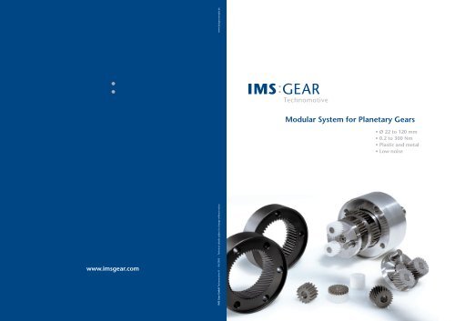
Modular System for <strong>Planetary</strong> Gears<br />
• Ø 22 to 120 mm<br />
• 0.2 to 300 Nm<br />
• Plastic and metal<br />
• Low-noise
Our planetary gearbox catalogue<br />
and what you’ll find in it<br />
This catalogue<br />
and its limits<br />
Our modular system offers almost 10,000<br />
combination options. This immense<br />
variety allows us to present only a selected<br />
number of gear units in this catalogue.<br />
If the unit you are loooking for is not listed,<br />
please contact us. We’d be pleased to help.<br />
Page<br />
2<br />
4<br />
6<br />
8<br />
10<br />
13<br />
15<br />
17<br />
19<br />
21<br />
23<br />
25<br />
27<br />
29<br />
31<br />
33<br />
35<br />
37<br />
Basic Information<br />
Thinking ahead<br />
Our vast expertise<br />
Our planetary gear units<br />
Our modular system for planetary gearboxes<br />
Your ultimate planetary gearbox<br />
Our type series<br />
metal (PM), plastic (PK) and low-noise (LN)<br />
ø 22mm PK 0.2 – 0.7 Nm<br />
ø 22mm PM 0.6 – 1.0 Nm<br />
ø 32mm PK 0.4 – 2.0 Nm<br />
ø 32mm PM/LN 0.8 – 4.5 Nm<br />
ø 42 mm PK 0.8 – 4.0 Nm<br />
ø 42mm PM/LN 3.0 – 15.0 Nm<br />
ø 52mm PK 2.0 – 10.0 Nm<br />
ø 52mm PM/LN 4.0 – 25.0 Nm<br />
ø 62mm PM/LN 8.0 – 50.0 Nm<br />
ø 72mm PM/LN 14.0 – 84.0 Nm<br />
ø 81mm PM/LN 20.0 – 120.0 Nm<br />
ø 105 mm PM/LN 35.0 – 195.0 Nm<br />
ø 120 mm PM 50.0 – 300.0 Nm<br />
41.2<br />
12<br />
12.1<br />
Gear reductions (fold-out page)<br />
Motor pinions (fold-out page)<br />
Specifications for motor attachment (fold-out page)<br />
39<br />
40<br />
41<br />
Additional information<br />
Bearing-mounted input shaft<br />
ATEX-requirements<br />
Conversion table<br />
“If you understand geometry<br />
you will understand everything in this world.”<br />
Galileo Galilei<br />
41.1<br />
Addresses and telephone numbers<br />
Locations (fold-out page)<br />
1
Clemens Rosenstiel and<br />
Norbert Willmann<br />
Directors <strong>IMS</strong> Gear GmbH<br />
Thinking ahead<br />
<strong>IMS</strong> Gear keeps the world on the move<br />
<strong>IMS</strong> Gear have been specialists in metal<br />
gearing, tooling and toothed-wheel<br />
engineering since 1863. In 1983, we added<br />
plastic materials to our product range.<br />
The entire value-added and responsibility<br />
chain from the development stage to final<br />
assembly is handled by us in-house. We<br />
have adapted the concept of “all under one<br />
roof” and taken it to its logical conclusion.<br />
The <strong>IMS</strong> Gear Technomotive Division<br />
supplies you with planetary gears in<br />
modular design in plastic, plastic-metal<br />
composites or in all-metal versions for<br />
the most varied of uses and for a wide<br />
range of applications.<br />
Our claim for consistent improvement of<br />
customer satisfaction goes back to our<br />
aim of a sustained and positive business<br />
development which, in turn, is based on<br />
our vision of the future and our long-term<br />
corporate strategy.<br />
Our expertise and experiences in the global<br />
automotive business in terms of product<br />
quality and technology leadership are our<br />
defining requirements in terms of speed,<br />
adaptability, reliability and efficiency.<br />
2<br />
3
Our vast expertise<br />
and what it means for you<br />
Software development for<br />
tooth profile enhancement<br />
Prototype and small batch production<br />
Process planning<br />
Equipment design<br />
and construction<br />
Logistics<br />
and delivery capability<br />
Design<br />
Gear cutting tooling<br />
Test laboratories<br />
Mould tool<br />
manufacture<br />
Series production<br />
Assembly<br />
1 2 3 4 5 6 7<br />
8 9 10<br />
11<br />
1 Software development for tooth<br />
profile enhancement<br />
We use our own software to improve tooth<br />
profiles beyond DIN standards. This means<br />
that our gears have less backlash, are more<br />
resistant to wear and tear with optimum<br />
performance in terms of strength.They are<br />
smoother and quieter running, and are<br />
less sensitive to tolerances.<br />
2 Design<br />
The in-house design department of<br />
<strong>IMS</strong> Gear Technomotive is consistently<br />
engaged in the development of the<br />
entire modular system. That's not all!<br />
Our team of experts is on standby for<br />
comprehensive and rapid adaptations<br />
to match your specific requirements<br />
and specifications.<br />
3 Gear cutting tooling<br />
We at <strong>IMS</strong> make our own tools for cutting<br />
the metal gears. This gives you an<br />
enormous advantage in lead time, and<br />
all the steps from theory to practice are<br />
handled by a single supplier.<br />
4 Prototype<br />
and small batch production<br />
<strong>IMS</strong> Gear Technomotive will supply you<br />
with custom-made sample gear units<br />
right through to small batches within<br />
a couple of days. We achieve this degree<br />
of flexibility with our comprehensive<br />
production capability and our<br />
independence from subcontractors<br />
and outside suppliers.<br />
5 Test laboratories<br />
In addition to the quality assurance<br />
accompanying Series production, <strong>IMS</strong><br />
Gear Technomotive continually carries<br />
out stress, wear and tear and life tests.<br />
Accompanying every development,<br />
our design department together with<br />
the Automotive division uses the noise<br />
laboratory and the climate testing<br />
laboratory of our Technology Centre<br />
in Donaueschingen.<br />
6 Process planning<br />
This is where <strong>IMS</strong> Gear Technomotive<br />
benefits from the immense wealth of<br />
experience of the Automotive division<br />
with its large batch production runs.<br />
The entire production process from<br />
development through to packaging is<br />
planned and optimised down to the<br />
last detail. The Technomotive standard<br />
toothed components are also large<br />
volume products. In-house process<br />
planning results in reliable production<br />
at minimum cost, low reject rates and<br />
ultimate quality.<br />
7 Mould tool manufacture<br />
The in-house production of plastic<br />
injection moulding tools allows us to<br />
realise and implement our own designs.<br />
It also provides measureable proof of<br />
our production capability and<br />
documentation.<br />
8 Equipment design and construction<br />
Since we design and build our own<br />
assembly and test equipment, production<br />
tooling, and parts feeding systems for our<br />
machines and their peripherals, we are<br />
capable of responding quickly and<br />
efficiently to complex production or<br />
customer specific requirements.<br />
9 Series production<br />
<strong>IMS</strong> Gear Technomotive makes virtually<br />
all its <strong>Planetary</strong> <strong>Gearbox</strong> components<br />
in-house. As both metal and plastic<br />
component production is in-house,<br />
we can produce quickly and with<br />
ultimate cost-efficiency.<br />
10 Assembly<br />
Manual assembly for a single unit<br />
is integrated in micro-batch production.<br />
We produce each series on dedicated<br />
assembly lines with large volume<br />
capacity; and we assemble customer<br />
or application specific gear solutions<br />
in high unit quantities on automated<br />
assembly units.<br />
11 Logistics and delivery capability<br />
We permanently hold stocks of all<br />
standard toothed parts for our modular<br />
planetary gearboxes. Many interfacing<br />
parts such as motor pinions, flanges or<br />
output shafts are in stock as semi-finished<br />
products.<br />
4 5
Our planetary gear units<br />
and what you should know about them<br />
8<br />
9<br />
7<br />
10<br />
6<br />
<strong>Planetary</strong> gears<br />
Mode of function<br />
<strong>Planetary</strong> gearboxes (PLGs) operate as their<br />
name implies: the motor-driven sun wheel<br />
is in the middle, transmitting its movement<br />
to three circumferential planet gears which<br />
form one stage. They are arranged on the<br />
bearing pins of a planet carrier. The last<br />
planet carrier in each sequence is rigidly<br />
linked to the output shaft and so ensures<br />
the power transmission to the output shaft.<br />
The planet gears run in an internally<br />
toothed outer ring gear.<br />
Properties<br />
Input and output are co-axial. The shafts<br />
turn in the same direction. PLGs are suitable<br />
for clockwise and anti-clockwise rotation, for<br />
alternating, continuous and cyclic operation,<br />
and they excel due to their high degree<br />
of efficiency. Unlike other gear types, their<br />
compact design provides ultimate power<br />
density and excellent torque transfer in the<br />
smallest space.<br />
Their resistance to shock loads is high due<br />
to load distribution over several components<br />
(the three planetary wheels) and the support<br />
of the annular gear.<br />
1<br />
Exploded drawing PM 72<br />
2<br />
3<br />
4<br />
5<br />
5<br />
1 Motor pinion input side<br />
2 Motor flange<br />
3 Metal planet gears, Stage 1<br />
4 Planet carrier, Stage 1<br />
5 Outer ring gear<br />
6 Metal planet gears and planet carrier, Stage 2<br />
7 Metal planet gears, Stage 3<br />
8 Output flange<br />
9 Ball bearing<br />
10 Output shaft<br />
Low-noise variant<br />
1 Motor pinion input side, helical toothing<br />
3 Plastic planet gears, helical toothing<br />
3<br />
PM 72 LN<br />
5 Outer ring gear, helical toothing<br />
1<br />
Connecting flanges<br />
This is where the flexibility of the PLG<br />
manufacturer really shows. <strong>IMS</strong> planetary<br />
gear units can be fitted to any (!) motor,<br />
with individual solutions possible on<br />
both the input side and the output side.<br />
Contact us with your specific<br />
requirements.<br />
Delivery<br />
<strong>IMS</strong> Gear Technomotive can supply your<br />
gearbox with the motor of your choice,<br />
fully assembled and inspected, or<br />
individually with separate motor pinion<br />
for remote assembly. We can also assist<br />
you with motor selection.<br />
Efficiency<br />
The inter-gear efficiency takes only the<br />
gear-making process into account,<br />
whereas the gearbox efficiency relates<br />
to the losses in the entire gearbox<br />
assembly. In this brochure we always<br />
specify the gearbox efficiency which is<br />
necessarily lower than the inter-gear<br />
efficiency. Since there are no standardised<br />
measuring methods, care is required<br />
when comparing the efficiency<br />
specified by different manufacturers.<br />
Gear backlash<br />
Gear backlash depends on a large<br />
number of factors: type of load, number<br />
of stages, bearing, design or material<br />
combination. When comparing different<br />
manufacturers, please note that there<br />
are also no standardised measurement<br />
methods. The values specified in this<br />
catalogue were measured with no load<br />
and with blocked input drive.<br />
Heat treatment<br />
The structural transformation during<br />
heat treatment of the metal components<br />
has positive effects on strength and wear<br />
performance of the gear units. <strong>IMS</strong> has its<br />
own heat treatment shop. Since we also<br />
have the entire metal machining activity<br />
in-house, we are capable of selecting<br />
from a wide choice of heat treatable alloy<br />
steels.<br />
Load on output shaft<br />
Different manufacturers use different<br />
methods of measurement making<br />
comparison difficult. Comparisons must<br />
be made with caution. The details in the<br />
<strong>IMS</strong> catalogue are based on the following<br />
conditions: rotational motor speed<br />
3,000 rpm, lowest reduction ratio for<br />
each stage, simultaneous axial and radial<br />
load, radial load in the centre of the<br />
driven shaft. Send us your specification<br />
and parameters, we'll be pleased to<br />
calculate the maximum axial and radial<br />
loads for your application. By modifying<br />
aspects of the basic design, we can also<br />
tolerate higher loads. Give us a call.<br />
Low-noise gears<br />
Optimum noise performance makes<br />
more stringent demands on true running<br />
and axial eccentricity of the motor<br />
bearing plate, flange and shaft. The<br />
helical toothing causes axial forces to<br />
act on the motor shaft, with the effect<br />
that adequate dimensioning of the motor<br />
shaft bearing must be ensured. To<br />
counter the grease-pumping effect of<br />
the helical toothing, radial shaft sealing<br />
gaskets or sealed motor bearings are<br />
recommended.<br />
Lubrication<br />
Our PLGs are grease-packed and therefore<br />
maintenance free throughout their life.<br />
Depending on the application, we<br />
select the best possible lubricant from as<br />
many as ten different options.<br />
Mounting position<br />
The grease lubrication and the different<br />
sealing modes allow the <strong>IMS</strong> planetary<br />
gears to be installed in any position.<br />
Operating temperature<br />
The operating temperature range<br />
depends on material selection and<br />
choice of lubricant. The temperature<br />
range of our all-metal versions with<br />
standard lubrication is between –30<br />
and +140 °C, that of the plastic PK<br />
series is between –15 and +65 °C.<br />
Operational dynamics<br />
Optimum operating dynamics are<br />
achieved through low moments of<br />
inertia, freedom of rotation and low<br />
wear and tear. Wherever appropriate,<br />
<strong>IMS</strong> Gear Technomotive uses plastic<br />
instead of metal for the planet gears<br />
and arranges these at balanced 120°<br />
angles. This results in low moments of<br />
inertia. If required, we achieve the<br />
ultimate ease of movement by fitting<br />
high-grade needle bearings or by<br />
selecting favourable friction values<br />
between metal and plastic. Wear is<br />
reduced by using a special gear tooth<br />
profile with tip relief and by using<br />
plastic wheels. Thus the selected <strong>IMS</strong><br />
material mix guarantees excellent<br />
operational dynamics.<br />
Output torque<br />
When selecting a planetary gear, the<br />
output torque or moment is one of the<br />
most important variables. The reduction<br />
ratio lowers the relatively high rotational<br />
motor speed to a lower output speed,<br />
increasing the output torque in inverse<br />
proportion. Please refer to page 10 to<br />
calculate the output.<br />
Overload torque<br />
The permitted overload torque (shock<br />
load) is defined as a short-term increase<br />
in output torque, e.g. during the start-up<br />
of a motor. In plastic PLGs, the peak<br />
torque equals the overload torque.<br />
In plastic-metal combinations or in<br />
all-metal versions, the overload torque<br />
can be as much as 1.5 times the peak<br />
load.<br />
Reduction ratios<br />
If the number of teeth of the sun wheel<br />
and the planetary wheels is changed,<br />
different reduction ratios are possible<br />
within one and the same stage. <strong>IMS</strong> Gear<br />
Technomotive combines these reduction<br />
ratios in as many as four stages and so<br />
achieves as many as 68 (!) non-integer<br />
reduction ratios. An enormous variety<br />
of different combinations can be<br />
implemented.<br />
Sealing modes<br />
The protection classes are defined in<br />
accordance with DIN 40500 Part 9.<br />
We are also capable of supplying output<br />
seals which will allow you to implement<br />
higher protection classes.<br />
Service life<br />
Depending on ambient and<br />
environmental conditions and on the<br />
operational specification of the driving<br />
system, the useful service life of a PLG<br />
is between 200 and 10,000 hours. The<br />
wide variety of potential applications<br />
prohibits generally applicable values for<br />
the useful service life.<br />
6<br />
7
Our modular system for planetary gearboxes<br />
and its almost 10,000 optional variants<br />
Even using standard gearing components,<br />
our modular system offers an immense<br />
variety of options. Also, pinion variants,<br />
flanges, outputs, bearings, lubricants and<br />
seals provide a wide range of options<br />
for virtually every combination. Since we<br />
stock all common parts, we are capable<br />
of delivering, even small quantities at short<br />
notice. For clarity, we have listed only<br />
the metal (P) or plastic (PK) PLG<br />
series in this catalogue, but we will<br />
send you any reasonable material mix<br />
on request. Give us a call. We are here<br />
to advise you.<br />
Motor pinions<br />
… virtually<br />
unlimited options<br />
Motor flange<br />
… to date, almost<br />
1,300 options<br />
<strong>Planetary</strong> gears<br />
PK/PM<br />
… to date, 1,270<br />
standard gear<br />
variants<br />
<strong>Planetary</strong> gears<br />
Low-noise<br />
1<br />
1<br />
1 2<br />
1 2<br />
1 2 3<br />
1 2 3<br />
1 2 3 4<br />
1 2 3 4<br />
…<br />
…<br />
Standard Standard<br />
Adaptation<br />
Our planetary gears are designed for connecting any<br />
current type of motor, using three different modes:<br />
with adaptable motor pinion in various designs, or<br />
using our option involving bearing-mounted input<br />
shafts. With appropriate quantities and after consultations<br />
with the motor manufacturer, the motor<br />
Nine different diameters with as many as four gear<br />
stages and a wide variety of reduction ratios ranging<br />
from 3.7:1 to 2,075.9:1 are available in plastic, metal<br />
or material mix versions with output torques ranging<br />
from 0.2 to 300 Nm. Although this results in an<br />
immense variety of options, we describe as standard<br />
The new low-noise modules for the first stage feature<br />
a well-attuned combination of module, number of<br />
teeth, helical angle, gearing width and choice of<br />
material, guaranteeing ultimate smooth running and<br />
high torque stability. With the new tandem planetary<br />
gears (patent applied for), even high peak loads are<br />
shaft can also be intermeshed directly. With an<br />
adapted motor mounting plate, the motor can then<br />
be connected to the annular wheel without any<br />
additional motor flange, allowing shorter and more<br />
cost-effective gearing assemblies.<br />
Flanges are available in plastic, die cast zinc or<br />
aluminium, as basic, standard or special flange,<br />
adapted individually depending on requirements.<br />
For diameters below 42 mm and with PK 52, the<br />
motor is connected to the gear via a special flange.<br />
For larger quantities you can also obtain toolspecific<br />
special flanges, e.g. made of plastic or<br />
die cast zinc. Type series P 52 to P 120 are also<br />
available with standard DIN 42948 flanges. In<br />
this case we recommend designing motor and<br />
flange according to DIN 42955-R.<br />
gearboxes which can be manufactured from any<br />
of our standard components and their variants.<br />
safely transfered. The external dimensions and<br />
reductions, identical to those of the straight-toothed<br />
gears and differing only in microns, allow easy<br />
replacement in most cases.<br />
Output flange<br />
… to date, over<br />
1,300 options<br />
Output<br />
… virtually<br />
unlimited<br />
adaptation<br />
options<br />
…<br />
…<br />
Adaptation<br />
The output flange includes the bearing. Sintered<br />
metal bearings or ball bearings can be selected to<br />
match the operating requirements. <strong>Gearbox</strong>es with<br />
two RS seals in the ball bearing of the output shaft<br />
are protection class IP 53, whereas with two Z cover<br />
disks they are protection class IP 42. Sintered metal<br />
The output shaft is linked to the last planet carrier<br />
and can be designed in any customer specific layout<br />
depending on the machine to be driven.<br />
versions are protection class IP 00. Higher protection<br />
classes can be implemented by applying specific<br />
seals.<br />
8 9
Your ultimate planetary gearbox<br />
and how to select it<br />
i = Reduction ratio<br />
n M = Motor speed<br />
n AB = Output speed<br />
T N = Nominal output torque<br />
T M = Motor torque<br />
η = Gear efficiency<br />
T AB = Output torque<br />
C B = Operating factor<br />
The T AB output torque is the most<br />
important variable when selecting the<br />
most suitable PLG. Use the equation<br />
compendium below to calculate this<br />
variable. The next important factor is<br />
the gear diameter.<br />
Once you have calculated the maximum<br />
output torque T AB , you can refer to the<br />
The reduction ratio i is used to reduce the<br />
relatively high motor speed n M<br />
to a lower<br />
output speed n AB<br />
.<br />
With:<br />
i = n M<br />
/ n AB<br />
Your desired nominal output torque T N<br />
is<br />
therefore calculated as follows:<br />
T N<br />
= T M<br />
• i • η<br />
To determine the reduction ratio i and<br />
the gear efficiency η, please refer to the<br />
appropriate type series in this catalogue.<br />
Determining the operating factor C B<br />
Direction Load (shocks) Daily operating time<br />
of rotation 3h 8h 24h<br />
constant none C B<br />
= 1.0 C B<br />
= 1.1 C B<br />
= 1.3<br />
medium C B<br />
= 1.2 C B<br />
= 1.3 C B<br />
= 1.5<br />
strong C B<br />
= 1.4 C B<br />
= 1.5 C B<br />
= 1.8<br />
alternating none C B<br />
= 1.3 C B<br />
= 1.4 C B<br />
= 1.6<br />
medium C B<br />
= 1.6 C B<br />
= 1.7 C B<br />
= 1.9<br />
strong C B<br />
= 1.9 C B<br />
= 2.0 C B<br />
= 2.2<br />
The maximum output torque T AB<br />
is calculated as follows:<br />
T AB<br />
= T N<br />
• C B<br />
diagram on the right to read the PLG<br />
type series with the appropriate diameter.<br />
In most cases and depending on the<br />
number of gearing stages, a T AB value<br />
can be implemented with several PLG<br />
type series. Any questions? Give us a call.<br />
We are there to help you.<br />
When calculating the actual output<br />
torque T AB<br />
, the calculated nominal<br />
output torque T N<br />
and the operating<br />
factor C B<br />
should also be taken into<br />
account. C B<br />
is merely a factor which<br />
addresses the different working<br />
conditions of a PLG and which is the<br />
result of your subjective appraisal. It is<br />
therefore only meant as a guide value.<br />
We include the following factors in the<br />
rough estimation of the operating factor<br />
C B<br />
: direction of rotation, load (shocks)<br />
and daily operating time.<br />
Refer to the table below to calculate<br />
the approximate operating factor C B<br />
.<br />
All details in the catalogue refer<br />
to C B<br />
= 1.0<br />
Therefore: T AB<br />
= T N<br />
Type series<br />
PK 22<br />
PM 22<br />
PK 32<br />
PM 32<br />
PM 32 LN<br />
PK 42<br />
PM 42<br />
PM 42 LN<br />
PK 52<br />
PM 52<br />
PM 52 LN<br />
PM 62<br />
PM 62 LN<br />
PM 72<br />
PM 72 LN<br />
Stages<br />
PM81 / PM81LN1<br />
2<br />
3<br />
4<br />
PM 105<br />
PM 105 LN<br />
PM 120<br />
1<br />
2<br />
3<br />
4<br />
1<br />
2<br />
3<br />
4<br />
1<br />
2<br />
3<br />
4<br />
1<br />
2<br />
3<br />
4<br />
1<br />
2<br />
3<br />
4<br />
1<br />
2<br />
3<br />
4<br />
1<br />
2<br />
3<br />
4<br />
1<br />
2<br />
3<br />
4<br />
1<br />
2<br />
3<br />
4<br />
1<br />
2<br />
3<br />
4<br />
1<br />
2<br />
3<br />
4<br />
0.2<br />
0.4<br />
0.6<br />
0.7<br />
0.4<br />
0.6<br />
0.7<br />
0.75<br />
0.8<br />
1.0<br />
1.0<br />
2.0<br />
2.0<br />
Once you have calculated the maximum output torque<br />
using the equation compendium on the left, you can<br />
then refer to the diagram on the top and see which<br />
<strong>IMS</strong> planetary gear matches. The figures in the type<br />
0.8<br />
2.0<br />
2.0<br />
2.25<br />
3.0<br />
4.0<br />
4.0<br />
4.0<br />
4.5<br />
4.5<br />
5.0<br />
7.5<br />
8.0<br />
permissible output torque T AB /Nm<br />
1<br />
50.0<br />
2<br />
150.0<br />
3<br />
4<br />
300.0<br />
300.0<br />
0 1<br />
5 10 25 50 150 300<br />
10.0<br />
10.0<br />
12.0<br />
14.0<br />
15.0<br />
15.0<br />
20.0<br />
25.0<br />
25.0<br />
25.0<br />
35.0<br />
42.0<br />
50.0<br />
50.0<br />
60.0<br />
84.0<br />
84.0<br />
105.0<br />
120.0<br />
120.0<br />
195.0<br />
195.0<br />
series description denote the gear diameter. Each <strong>IMS</strong><br />
type series is available with four stages, which means<br />
that several diameters are often available for one and<br />
the same output torque.<br />
T AB<br />
/ Nm<br />
10<br />
11
Please open up!<br />
Alternative motor pinion variants<br />
Short pinion<br />
Bushing + pinion<br />
Cup-type pinion<br />
Clamp-type pinion<br />
Geared shaft<br />
Attachment options<br />
• pinning<br />
• cross thread<br />
• keyway<br />
• pressfit<br />
• bonding<br />
• clamping<br />
12
Specifications for motor attachment<br />
Intermediate flange<br />
Motor<br />
Motorshaft<br />
Cylindrial shaft end (Z)<br />
DIN 42946<br />
Basic flange<br />
Thrust ring thickness f<br />
Motor pinion<br />
Design variant:<br />
Bushing + pinion<br />
Bore out cross hole Ø q<br />
for tension pin DIN 1481<br />
b<br />
k<br />
c<br />
h<br />
a<br />
o max.<br />
m<br />
p max.<br />
n<br />
Tension pin<br />
DIN 1481<br />
(drilling off with motor shaft)<br />
Thread d -4x90°<br />
(Shown offset by 45°)<br />
i<br />
e<br />
l<br />
g<br />
PM32 PK32 PM42 PK42 PM52 PK52 PM62 PM72 PM81 PM105 PM120<br />
PM32LN PM42LN PM52LN PM62LN PM72LN PM81LN PM105LN<br />
Pinion Flange<br />
a 32 32 42 42 52 52 62 72 81 105 120<br />
b 14 H8 14 H8 20 H7 20 H7 30 H7 30 H8 40 H7 40 H7 40 H7 50 H7 60 H7<br />
c 28.1 – 0,15 28.1 – 0.15 33.3 33.3 42.5 42.5 51 59 69.5 86 100<br />
d M2 M2 M4 M4 M4 M4 M5 M6 M6 M10 M10<br />
e 11 11 10.4 10 10.4 10 15.4 20 18.5 20 20<br />
f 0.2 0.2 0.2 0.2 0.3 0.3 0.3 0.5 0.3 0.5 0.5<br />
g 6.1 – 0.4 6.1 – 0.4 8 + 0.3 8 + 0.3 8 + 0.3 8 + 0.3 10,4 – 0.3 12.1 – 0.3<br />
+ 0.15<br />
13,5 – 0.25 18.3 – 0.3<br />
+ 0.2<br />
19,4 – 0.3<br />
h – – 39 – 0.02 – 49 – 0.02 – 59 – 0.025 69 – 0.025 78 – 0.025 100 – 0.025 115 k7<br />
i – – 2.5 – 3 – 3.0 3.5 3.5 3.5 3.3<br />
k 22.1 – 0.02<br />
* 22.1 – 0.02 24.2 – 0.2 24.7 – 0.03 32,8 – 0.2 33.34 – 0.03 39 – 0.2 42.5 – 0.2 51.8 – 0.2 63.8 – 0.2 76 ± 0.1<br />
l 1.8 + 0.1 1.8 + 0.1 2 + 0.1 2.5 + 0.1 2 + 0.1 2.5 + 0.1 2 + 0.1 2 + 0.1 2 +0.1 2 + 0.1 6.1 ± 0.05<br />
m 10 10 11–12 11 15 15 18 – 20 20 24 30 35.6<br />
n 16 16 27.5 27.5 34 34 38 41.4 48.5 60 70<br />
o 3 3 7 7 10 10 12 14 18 21 26<br />
p 6 6 11 11 16 16 18 19 21 26 28<br />
q – – 2 2 3 3 3 3 3 5 5<br />
* k in PM32LN is = 21,1 – 0.02<br />
12 X .1
PK 22<br />
PK 22<br />
Parameter 1-stage 2-stage 3-stage 4-stage<br />
Perm. output torque (Appl. factor C B =1.0) 0.2 Nm 0.4 Nm 0.6 Nm 0.7 Nm<br />
<strong>Gearbox</strong> efficiency, approx. 0.80 0.75 0.70 0.65<br />
Max. backlash in ° DEG 1.50° 2.00° 2.50° 3.00°<br />
Recommended initial speed 6,000 rpm 6,000 rpm 6,000 rpm 6,000 rpm<br />
Operating temperature -15 °C to +65 °C -15 °C to +65 °C -15 °C to +65 °C -15 °C to +65 °C<br />
Output side with sintered metal bearing<br />
Max. load, radial (10mm from flange) 15 N 30 N 45 N 60 N<br />
Max. load, axial 30 N 30 N 30 N 30 N<br />
Max. perm.fitting pressure 150 N 150 N 150 N 150 N<br />
<strong>Gearbox</strong> length p 26.6 ± 0.5mm 34.8 ± 0.5mm 43.0 ± 0.5mm 51.2 ± 0.5mm<br />
Ø x Total length 22.0 x 41.1 mm 22.0 x 49.3 mm 22.0 x 57.5 mm 22.0 x 65.7 mm<br />
Weight 41 g 52 g 63 g 74 g<br />
· Gear reductions see last page (fold-out page)<br />
p<br />
14.5<br />
3.4<br />
4.5<br />
Ø17<br />
3x120°<br />
Ø 2.2<br />
1.8<br />
2<br />
8<br />
Ø 10 H8<br />
Basic design<br />
3.5<br />
Ø 4 h7<br />
Ø6<br />
Ø 14 h8<br />
60°<br />
Ø 3 H7<br />
Ø19<br />
M2<br />
3.2<br />
4<br />
4.7–0.3 Assembly dim.<br />
Depth of tapped hole<br />
max. 3.5 mm<br />
3x 120°<br />
Ø22<br />
Refer to the above table for the values of p.<br />
Ordering codes<br />
01 Basic flange<br />
06 Special flange<br />
09 Bearing-mounted input shaft (see page 39)<br />
Order example<br />
You wish to order a plastic planetary gear with a diameter of 22 mm of type series<br />
PK 22 with the reduction ratio 169:1, with basic flange on the motor and output side.<br />
Feel free to contact us – we are happy to help you<br />
PK 22. 169. 01 / 01<br />
<strong>Planetary</strong> gear, plastic<br />
Type series<br />
Reduction ratio rounded<br />
Flange, motor side (see ordering codes)<br />
Flange, output side (see ordering codes)<br />
The details given herein are recommended values. Minor variances due to reduction ratios or non-standard testing or measuring methods<br />
etc. may occur. Please refer to pages 6 to 11 and 39 of this catalogue for basic or additional information, or contact us directly. Technical<br />
details subject to change without notice.<br />
12 .2<br />
13
PM 22<br />
PM 22<br />
Parameter 1-stage 2-stage 3-stage 4-stage<br />
Perm. output torque (Appl. factor C B =1.0) 0.6 Nm 0.7 Nm 0.8 Nm 1.0 Nm<br />
<strong>Gearbox</strong> efficiency, approx. 0.90 0.80 0.70 0.60<br />
Max. backlash in ° DEG 1.5° 2.0° 2.5° 3.0°<br />
Recommended initial speed 6,000 rpm 6,000 rpm 6,000 rpm 6,000 rpm<br />
Operating temperature -15 °C to +65 °C -15 °C to +65 °C -15 °C to +65 °C -15 °C to +65 °C<br />
Output side with sintered metal bearing<br />
Max. load, radial (10mm from flange) 80 N 80 N 80 N 80 N<br />
Max. load, axial 30 N 30 N 30 N 30 N<br />
Max. perm. fitting pressure 150 N 150 N 150 N 150 N<br />
<strong>Gearbox</strong> length p 19.7 ± 0.3mm 26.4 ± 0.3mm 33.1 ± 0.3mm 39.8 ± 0.3mm<br />
Ø x Total length 22.0 x 34.2 mm 22.0 x 40.9 mm 22.0 x 47.6 mm 22.0 x 54.3 mm<br />
Weight 48 g 61 g 74 g 87 g<br />
· Gear reductions see last page (fold-out page)<br />
p 14.5<br />
2.4<br />
3<br />
Ø17<br />
3x120°<br />
Ø2.2<br />
0.8<br />
2<br />
8<br />
Ø10<br />
H8<br />
Basic design<br />
3.5<br />
Ø 4 h7<br />
Ø 3 H7<br />
Ø 14 h8<br />
60°<br />
M3<br />
2.5<br />
min. 3.5<br />
3x120°<br />
Ø18<br />
3.7– 0.3 Assembly dimension<br />
Ø22<br />
Refer to the above table for the values of p.<br />
Ordering codes<br />
01 Basic flange<br />
06 Special flange<br />
09 Bearing-mounted input shaft (see page 39)<br />
Order example<br />
You wish to order a metal planetary gear with a diameter of 22 mm of type series PM 22<br />
with the reduction ratio 169:1, with basic flange on the motor and output side.<br />
Feel free to contact us – we are happy to help you<br />
PM 22. 169. 01 / 01<br />
<strong>Planetary</strong> gear, metal<br />
Type series<br />
Reduction ratio rounded<br />
Flange, motor side (see ordering codes)<br />
Flange, output side (see ordering codes)<br />
The details given herein are recommended values. Minor variances due to reduction ratios or non-standard testing or measuring methods<br />
etc. may occur. Please refer to pages 6 to 11 and 39 of this catalogue for basic or additional information, or contact us directly. Technical<br />
details subject to change without notice.<br />
14<br />
15
PK 32<br />
PK 32<br />
Parameter 1-stage 2-stage 3-stage 4-stage<br />
Perm. output torque (Appl. factor C B =1.0) 0.4 Nm 1.0 Nm 2.0 Nm 2.0 Nm<br />
<strong>Gearbox</strong> efficiency, approx. 0.75 0.70 0.65 0.60<br />
Max. backlash in ° DEG 1.90° 1.95° 2.00° 2.05°<br />
Recommended initial speed 3,000 rpm 3,000 rpm 3,000 rpm 3,000 rpm<br />
Operating temperature -15 °C to +65 °C -15 °C to +65 °C -15 °C to +65 °C -15 °C to +65 °C<br />
Output side with sintered metal bearing<br />
Max. load, radial 15 N 30 N 45 N 45 N<br />
Max. load, axial 5 N 10 N 15 N 15 N<br />
Max. perm. fitting pressure 150 N 150 N 150 N 150 N<br />
<strong>Gearbox</strong> length p 36.0 ± 0.5mm 45.5 ± 0.5mm 55.0 ± 0.5mm 64.7 ± 0.5mm<br />
Ø x Total length 32.0 x 56.0mm 32.0 x 65.5 mm 32.0 x 75.0 mm 32.0 x 84.7 mm<br />
Weight 100 g 115 g 130 g 145 g<br />
Output side with ball bearing (2Z)<br />
Max. load, radial 40 N 70 N 100 N 100 N<br />
Max. load, axial 10 N 20 N 30 N 30 N<br />
Max. perm. fitting pressure 120 N 120 N 120 N 120 N<br />
<strong>Gearbox</strong> length p 32.3 ± 0.5mm 41.8 ± 0.5mm 51.3 ± 0.5mm 61.0 ± 0.5mm<br />
Ø x Total length 32.0 x 52.3 mm 32.0 x 61.8 mm 32.0 x 71.3 mm 32.0 x 81.0 mm<br />
Weight 120 g 135 g 150 g 165 g<br />
· Gear reductions see last page (fold-out page)<br />
· Specifications for motor attachment see page 12.1 (fold-out page)<br />
p<br />
20<br />
Ø32<br />
3.4<br />
Ø26<br />
Ø29<br />
3<br />
Ø 14 H8<br />
Basic design<br />
Ø 6 g6<br />
Ø 20 h10<br />
Ø3.2<br />
M3x7<br />
11<br />
10<br />
Ø22<br />
Refer to the above table for the values of p.<br />
Ordering codes<br />
01 Basic flange<br />
06 Special flange<br />
07 Bearing flange of plastic, sintered bearing on output shaft<br />
08 Bearing flange of die-cast zinc, ball bearing on output shaft<br />
09 Bearing-mounted input shaft (see page 39)<br />
Order example<br />
You wish to order a plastic planetary gear with a diameter of 32 mm of type series PK 32,<br />
with the reduction ratio 46:1, basic flange on motor side, bearing flange of plastic, sintered<br />
bearing on output side.<br />
Feel free to contact us – we are happy to help you<br />
PK 32. 46. 01 / 07<br />
<strong>Planetary</strong> gear, plastic<br />
Type series<br />
Reduction ratio rounded<br />
Flange, motor side (see ordering codes)<br />
Flange, output side (see ordering codes)<br />
The details given herein are recommended values. Minor variances due to reduction ratios or non-standard testing or measuring methods<br />
etc. may occur. Please refer to pages 6 to 11 and 39 of this catalogue for basic or additional information, or contact us directly. Technical<br />
details subject to change without notice.<br />
16 17
PM 32 | PM 32 LN<br />
PM 32 | PM 32 LN<br />
Parameter 1-stage 2-stage 3-stage 4-stage<br />
NEMA flange 14<br />
26<br />
M3<br />
Ø3.4<br />
12<br />
Shown offset<br />
Ø32<br />
Ø 22 h8<br />
Ø22<br />
H7<br />
26<br />
Perm. output torque (Appl. factor C B =1.0) 0.75 Nm 2.25 Nm 4.50 Nm 4.50 Nm<br />
<strong>Gearbox</strong> efficiency, approx. 0.80 0.75 0.70 0.65<br />
Max. backlash in ° DEG 1.50° (LN: 2.00°) 1) 1.55° 1.60° 1.65°<br />
Recommended initial speed 3,000 rpm 3,000 rpm 3,000 rpm 3,000 rpm<br />
Operating temperature -30 °C to +140 °C -30 °C to +140 °C -30 °C to +140 °C -30 °C to +140 °C<br />
2<br />
26<br />
21.5<br />
7.5<br />
35.3<br />
q<br />
Refer to the table on the right for the values of q.<br />
26<br />
35.3<br />
Output side with ball bearing (2Z)<br />
Max. load, radial 40 N 70 N 100 N 130 N<br />
Max. load, axial 10 N 20 N 30 N 40 N<br />
Max. perm. fitting pressure 120 N 120 N 120 N 120 N<br />
<strong>Gearbox</strong> length p 32.3 mm ± 0.5mm 41.8 mm ± 0.5mm 51.3 mm ± 0.5mm 60.8 mm ± 0.5mm<br />
<strong>Gearbox</strong> length q 43.5 mm ± 0.5mm 53.0 mm ± 0.5mm 62.5 mm ± 0.5mm 72.0 mm ± 0.5mm<br />
ØxTotal length(p+lengthfrombearingflange) 32.0 x 52.0 mm 32.0 x 61.5 mm 32.0 x 71.0 mm 32.0 x 80.5 mm<br />
Weight (for gearbox length p) 160 g 210 g 260 g 310 g<br />
1) For plastic PL wheels only! Impact of 1st stage for 2-4 stage versions is negligible. · Gear reductions see last page (fold-out page)<br />
· Specifications for motor attachment see page 12.1 (fold-out page)<br />
Ø32<br />
p<br />
20<br />
Ø26<br />
3<br />
Ø 6 g6<br />
Ø3.2<br />
Ø 14 H8<br />
depth 3<br />
Basic design<br />
Ø 20 h8<br />
M3x4<br />
11<br />
6.5<br />
Ø22<br />
Refer to the above table for the values of p.<br />
Ordering codes<br />
01 Basic flange<br />
06 Special flange<br />
09 Bearing-mounted input shaft (see page 39)<br />
14 NEMA flange<br />
Order example<br />
You wish to order a metal planetary gear with a diameter of 32 mm of type series PM 32<br />
with the reduction ratio 35:1, with basic flange on the motor and output side.<br />
Feel free to contact us – we are happy to help you<br />
PM 32 LN. 35. 01 / 01<br />
<strong>Planetary</strong> gear, metal<br />
Type series<br />
Low-noise design<br />
Reduction ratio rounded<br />
Flange, motor side (see ordering codes)<br />
Flange, output side (see ordering codes)<br />
The details given herein are recommended values. Minor variances due to reduction ratios or non-standard testing or measuring methods<br />
etc. may occur. Please refer to pages 6 to 11 and 39 of this catalogue for basic or additional information, or contact us directly. Technical<br />
details subject to change without notice.<br />
18 19
PK 42<br />
PK 42<br />
Parameter 1-stage 2-stage 3-stage 4-stage<br />
Perm. output torque (Appl. factor C B =1.0) 0.8 Nm 2.0 Nm 4.0 Nm 4.0 Nm<br />
<strong>Gearbox</strong> efficiency, approx. 0.80 0.75 0.70 0.65<br />
Max. backlash in ° DEG 1.70° 1.75° 1.80° 1.85°<br />
Recommended initial speed 3,000 rpm 3,000 rpm 3,000 rpm 3,000 rpm<br />
Operating temperature -15 °C to +65 °C -15 °C to +65 °C -15 °C to +65 °C -15 °C to +65 °C<br />
Output side with sintered metal bearing<br />
Max. load, radial 15 N 30 N 45 N 45 N<br />
Max. load, axial 5 N 10 N 30 N 30 N<br />
Max. perm.fitting pressure 150 N 150 N 150 N 150 N<br />
<strong>Gearbox</strong> length p 48.9 ± 0.5mm 61.9 ± 0.5mm 74.9 ± 0.5mm 87.9 ± 0.5mm<br />
Ø x Total length 42.0 x 73.9 mm 42.0 x 86.9 mm 42.0 x 99.9 mm 42.0 x 112.9 mm<br />
Weight 200 g 300 g 400 g 500 g<br />
Output side with ball bearing (2RS)<br />
Max. load, radial 160 N 230 N 300 N 300 N<br />
Max. load, axial 50 N 80 N 110 N 110 N<br />
Max. perm.fitting pressure 320 N 320 N 320 N 320 N<br />
<strong>Gearbox</strong> length p 48.9 ± 0.5mm 61.9± 0.5mm 74.9 ± 0.5mm 87.9 ± 0.5mm<br />
Ø x Total length 42.0 x 73.9 mm 42.0 x 86.9 mm 42.0 x 99.9 mm 42.0 x 112.9 mm<br />
Weight 400 g 500 g 600 g 700 g<br />
· Gear reductions see last page (fold-out page)<br />
· Specifications for motor attachment see page 12.1 (fold-out page)<br />
Ø42<br />
Ø36<br />
p 25<br />
2.8<br />
Key, keyway DIN 6885 – A3x3x16<br />
Ctrg. DIN 332 – D M3<br />
Ordering codes<br />
01 Basic flange<br />
06 Special flange<br />
07 Bearing flange of plastic, sintered bearing on output shaft<br />
08 Bearing flange of plastic, ball bearing on output shaft<br />
09 Bearing-mounted input shaft (see page 39)<br />
10 Bearing flange of plastic, direct bearing<br />
Basic design<br />
Ø H7<br />
Ø 32<br />
2<br />
3<br />
20<br />
Ø2.5 – 0.1<br />
10<br />
17.1<br />
Ø33.3<br />
depth 3<br />
30° 30°<br />
M4x10<br />
max. 9<br />
Refer to the above table for the values of p.<br />
M4<br />
Ø33<br />
Ø 8 g6<br />
Ø 25 h10<br />
Order example<br />
You wish to order a plastic planetary gear with a diameter of 42 mm of type series PK 42<br />
with the reduction ratio 46:1, special flange on motor side, bearing flange of plastic,<br />
sintered bearing on output side.<br />
Feel free to contact us – we are happy to help you<br />
PK 42. 46. 06 / 07<br />
<strong>Planetary</strong> gear, plastic<br />
Type series<br />
Reduction ratio rounded<br />
Flange, motor side (see ordering codes)<br />
Flange, output side (see ordering codes)<br />
The details given herein are recommended values. Minor variances due to reduction ratios or non-standard testing or measuring methods<br />
etc. may occur. Please refer to pages 6 to 11 and 39 of this catalogue for basic or additional information, or contact us directly. Technical<br />
details subject to change without notice.<br />
20<br />
21
PM 42 | PM 42 LN<br />
PM 42 | PM 42 LN<br />
Parameter 1-stage 2-stage 3-stage 4-stage<br />
NEMA flange 17<br />
31<br />
M3<br />
Ø 3.2<br />
10.5<br />
Shown offset<br />
Ø42<br />
Ø 22 h8<br />
Ø22H7<br />
31<br />
Perm. output torque (Appl. factor C B =1.0) 3.0 Nm 7.5 Nm 15.0 Nm 15.0 Nm<br />
<strong>Gearbox</strong> efficiency, approx. 0.80 0.75 0.70 0.65<br />
Max. backlash in ° DEG 0.90° (LN: 1.30°) 1) 0.95° 1.00° 1.05°<br />
Recommended initial speed 3,000 rpm 3,000 rpm 3,000 rpm 3,000 rpm<br />
Operating temperature -30 °C to +140 °C -30 °C to +140 °C -30 °C to +140 °C -30 °C to +140 °C<br />
31<br />
42.1<br />
30.5<br />
2<br />
20.6<br />
q<br />
Refer to the table on the right for the values of q.<br />
31<br />
42.1<br />
Output side with ball bearing (2RS)<br />
Max. load, radial 160 N 230 N 300 N 360 N<br />
Max. load, axial 50 N 80 N 110 N 140 N<br />
Max. perm. fitting pressure 320 N 320 N 320 N 320 N<br />
<strong>Gearbox</strong> length p 49.1 ± 0.5mm 62.2 ± 0.5m 75.3 ± 0.5mm 88.4 ± 0.5mm<br />
<strong>Gearbox</strong> length q 72.6 ± 0.5mm 85.7 ± 0.5mm 98.8 ± 0.5mm 111.9 ± 0.5mm<br />
ØxTotal length(p+lengthfrombearingflange) 42.0 x 74.1 mm 42.0 x 87.2 mm 42 x 100,3 mm 42.0 x 113.4 mm<br />
Weight (for gearbox length p) 400 g 500 g 600 g 700 g<br />
1) For plastic PL wheels only! Impact of 1st stage for 2-4 stage versions is negligible. · Gear reductions see last page (fold-out page)<br />
· Specifications for motor attachment see page 12.1 (fold-out page)<br />
Ø42<br />
Ø36<br />
p<br />
2.8<br />
25<br />
Key, keyway DIN 6885 – A3x3x16<br />
Ctrg. DIN 332 – D M3<br />
Ø32<br />
2<br />
3<br />
8g6<br />
Ø20<br />
H7<br />
depth 3<br />
Basic design<br />
30°<br />
30°<br />
M4<br />
Ø 25 h9<br />
M3x10<br />
M4x10<br />
max. 9<br />
7.9 27.5<br />
Ø33.3<br />
Refer to the above table for the values of p.<br />
Ordering codes<br />
01 Basic flange<br />
06 Special flange<br />
09 Bearing-mounted input shaft (see page 39)<br />
17 NEMA flange<br />
Order example<br />
You wish to order a metal planetary gear with a diameter of 42 mm of type series PM 42<br />
with the reduction ratio 46:1, special flange on motor side, basic flange on output side.<br />
Feel free to contact us – we are happy to help you<br />
PM 42 LN. 46. 06 / 01<br />
<strong>Planetary</strong> gear, metal<br />
Type series<br />
Low-noise design<br />
Reduction ratio rounded<br />
Flange, motor side (see ordering codes)<br />
Flange, output side (see ordering codes)<br />
The details given herein are recommended values. Minor variances due to reduction ratios or non-standard testing or measuring methods<br />
etc. may occur. Please refer to pages 6 to 11 and 39 of this catalogue for basic or additional information, or contact us directly. Technical<br />
details subject to change without notice.<br />
22<br />
23
PK 52<br />
PK 52<br />
Parameter 1-stage 2-stage 3-stage 4-stage<br />
Perm. output torque (Appl. factor C B =1.0) 2.0 Nm 5.0 Nm 10.0 Nm 10.0 Nm<br />
<strong>Gearbox</strong> efficiency, approx. 0.75 0.70 0.65 0.60<br />
Max. backlash in ° DEG 1.10° 1.15° 1.20° 1.25°<br />
Recommended initial speed 3,000 rpm 3,000 rpm 3,000 rpm 3,000 rpm<br />
Operating temperature -15 °C to +65 °C -15 °C to +65 °C -15 °C to +65 °C -15 °C to +65 °C<br />
Output side with ball bearing (2RS)<br />
Max. load, radial 200 N 320 N 450 N 500 N<br />
Max. load, axial 60 N 100 N 150 N 200 N<br />
Max. perm. fitting pressure 500 N 500 N 500 N 500 N<br />
<strong>Gearbox</strong> length p 55.1 ± 0.5mm 69.2 ± 0.5mm 83.3 ± 0.5mm 97.4 ± 0.5mm<br />
Ø x Total length 52.0 x 80.1 mm 52.0 x 94.2 mm 52.0 x 108.3 mm 52.0 x 122.4 mm<br />
Weight 400 g 500 g 600 g 700 g<br />
· Gear reductions see last page (fold-out page)<br />
· Specifications for motor attachment see page 12.1 (fold-out page)<br />
Key, keyway DIN 6885 – A 4x4x16<br />
Ø52<br />
p<br />
4.2<br />
25<br />
Ctrg. DIN 332 – D M4<br />
Ø40<br />
Ø47<br />
3<br />
2.5<br />
Ø30H8<br />
depth 3<br />
Basic design<br />
Ø 32 h8<br />
M4<br />
Ø 12 h7<br />
M5x10<br />
max. 8<br />
10 22.3<br />
Ø42.5<br />
Refer to the above table for the values of p.<br />
Ordering codes<br />
01 Basic flange<br />
06 Special flange<br />
09 Bearing-mounted input shaft (see page 39)<br />
Order example<br />
You wish to order a plastic planetary gear, with a diameter of 52 mm of type series PK 52<br />
with the reduction ratio 25:1, bearing-mounted input shaft on motor side, basic flange on<br />
output side.<br />
Feel free to contact us – we are happy to help you<br />
PK 52. 25. 09 / 01<br />
<strong>Planetary</strong> gear, plastic<br />
Type series<br />
Reduction ratio rounded<br />
Flange, motor side (see ordering codes)<br />
Flange, output side (see ordering codes)<br />
The details given herein are recommended values. Minor variances due to reduction ratios or non-standard testing or measuring methods<br />
etc. may occur. Please refer to pages 6 to 11 and 39 of this catalogue for basic or additional information, or contact us directly. Technical<br />
details subject to change without notice.<br />
24<br />
25
PM 52 | PM 52 LN<br />
PM 52 | PM 52 LN<br />
Parameter 1-stage 2-stage 3-stage 4-stage<br />
Standard flange<br />
b 2<br />
3<br />
s<br />
c3<br />
b3<br />
w3<br />
Perm. output torque (Appl. factor C B =1.0) 4.0 Nm 12.0 Nm 25.0 Nm 25.0 Nm<br />
<strong>Gearbox</strong> efficiency, approx. 0.80 0.75 0.70 0.65<br />
Max. backlash in ° DEG 0.70° (LN: 1,10°) 1) 0.75° 0.80° 0.85°<br />
Recommended initial speed 3,000 rpm 3,000 rpm 3,000 rpm 3,000 rpm<br />
Operating temperature -30 °C to +140 °C -30 °C to +140 °C -30 °C to +140 °C -30 °C to +140 °C<br />
s2<br />
e2<br />
a2<br />
n3<br />
u3<br />
Shown<br />
offset<br />
Refer to the table on the right for the values of k.<br />
k<br />
f2<br />
c2<br />
Dim.of motor mount./flange 1) a 3 b 3 w 3 c 3 e 3 n 3 u 3 s 3<br />
C 80 2) 80 50 H7 38 H7 10.2 65 3 5.5 5.5<br />
C 105 2) 105 70 H7 10.2 85 3 6.5<br />
Dimensions of gear unit output/flange a 2 b 2 c 2 e 2 f 2 s 2<br />
C 80 80 50 j7 9 65 2.5 M5<br />
C 90 90 60 j7 9 75 2.5 5.5<br />
C 105 105 70 j7 9 85 2.5 6.5<br />
C 120 120 80 j7 9 100 3.0 6.5<br />
e3<br />
a3<br />
Output side with ball bearing (2RS)<br />
Max. load, radial 200 N 320 N 450 N 500 N<br />
Max. load, axial 60 N 100 N 150 N 200 N<br />
Max. perm. fitting pressure 500 N 500 N 500 N 500 N<br />
<strong>Gearbox</strong> length p 55.3 ± 0.5mm 69.5 ± 0.5mm 83.7 ± 0.5mm 97.9 ± 0.5mm<br />
<strong>Gearbox</strong> length k (motorsize 56) 82.0 ± 0.5mm 96.2 ± 0.5mm 110.4 ± 0.5mm 124.6 ± 0.5mm<br />
<strong>Gearbox</strong> length q 76.6 ± 0.6mm 90.8 ± 0.6mm 105.0 ± 0.6mm 119.2 ± 0.6mm<br />
ØxTotal length(p+lengthfrombearingflange) 52.0 x 80.3 mm 52.0 x 94.5 mm 52.0 x 108.7 mm 52.0 x 122.9 mm<br />
Weight (for gearbox length p) 0.7 kg 0.9 kg 1.1 kg 1.3 kg<br />
1) For plastic PL wheels only! Impact of 1st stage for 2-4 stage versions is negligible. · Gear reductions see last page (fold-out page)<br />
· Specifications for motor attachment see page 12.1 (fold-out page)<br />
Ø52<br />
p<br />
4.2<br />
25<br />
Key, keyway DIN 6885 – A4x4x16<br />
Ctrg. DIN 332 – D M4<br />
1) standard motors<br />
2) motor size 56 (B14, B3/B14)<br />
Basic design<br />
Ø5<br />
10<br />
Shown offset<br />
Ø38.1H7<br />
Ø40<br />
3<br />
2.5<br />
Ø30<br />
H8<br />
depth 3<br />
NEMA flange 23<br />
47.14<br />
M5<br />
Ø52<br />
Ø38.1 h8<br />
47.14<br />
56.4<br />
30.3<br />
1.5<br />
6<br />
q<br />
Refer to the table on the right for the values of q.<br />
47.14<br />
56.4<br />
47.14<br />
M5x10<br />
M4<br />
max. 8<br />
7.4 33<br />
Ø 12 h7<br />
Ø 32 h8<br />
Ø 42.5<br />
Refer to the above table for the values of p.<br />
Ordering codes<br />
01 Basic flange<br />
02 C 80<br />
03 C 90<br />
04 C 105<br />
05 C 120<br />
06 Special flange<br />
09 Bearing-mounted input shaft (see page 39)<br />
23 NEMA flange<br />
Order example<br />
You wish to order a metal planetary gear with a diameter of 52 mm of type series PM 52<br />
with the reduction ratio 46:1, special flange on motor side, basic flange on output side.<br />
Feel free to contact us – we are happy to help you<br />
PM 52 LN. 46. 06 / 01<br />
<strong>Planetary</strong> gear, metal<br />
Type series<br />
Low-noise design<br />
Reduction ratio rounded<br />
Flange, motor side (see ordering codes)<br />
Flange, output side (see ordering codes)<br />
The details given herein are recommended values. Minor variances due to reduction ratios or non-standard testing or measuring methods<br />
etc. may occur. Please refer to pages 6 to 11 and 39 of this catalogue for basic or additional information, or contact us directly. Technical<br />
details subject to change without notice.<br />
26<br />
27
PM 62 | PM 62 LN<br />
PM 62 | PM 62 LN<br />
Parameter 1-stage 2-stage 3-stage 4-stage<br />
b 2<br />
2<br />
Standard flange<br />
3<br />
s<br />
c3 b3<br />
Perm. output torque (Appl. factor C B =1.0) 8 Nm 25 Nm 50 Nm 50 Nm<br />
<strong>Gearbox</strong> efficiency, approx. 0.80 0.75 0.70 0.65<br />
Max. backlash in ° DEG 0.65° (LN: 0,95°) 1) 0.70° 0.75° 0.80°<br />
Recommended initial speed 3,000 rpm 3,000 rpm 3,000 rpm 3,000 rpm<br />
Operating temperature -30 °C to +140 °C -30 °C to +140 °C -30 °C to +140 °C -30 °C to +140 °C<br />
s2<br />
e<br />
a2<br />
n3<br />
Shown<br />
offset<br />
Refer to the table on the right for the values of k.<br />
k<br />
f2<br />
c2<br />
Dim.of motor mount./flange 1) a 3 b 3 c 3 e 3 n 3 s 3<br />
C 80 2) 80 50 H7 7 65 3.0 5.5<br />
C 105 2) 105 70 H7 7 85 3.0 6.5<br />
C 90 3) 90 60 H7 7 75 3.0 5.5<br />
C 120 3) 120 80 H7 7 100 3.5 6.5<br />
e3<br />
a3<br />
Output side with ball bearing (2RS)<br />
Max. load, radial 240 N 360 N 520 N 640 N<br />
Max. load, axial 70 N 100 N 150 N 200 N<br />
Max. perm. fitting pressure 1,000 N 1,000 N 1,000 N 1,000 N<br />
<strong>Gearbox</strong> length p 58.2 ± 0.5mm 75.1 ± 0.5mm 92.0 ± 0.5mm 108.9 ± 0.5mm<br />
<strong>Gearbox</strong> length k (motorsize 56 and 63) 82.3 ± 0.6mm 99.2 ± 0.6mm 116.1 ± 0.6mm 133.0 ± 0.6mm<br />
ØxTotal length(p+lengthfrombearingflange) 62.0 x 97.2 mm 62.0 x 114.1 mm 62.0 x 131.0 mm 62.0 x 147.9 mm<br />
Weight (for gearbox length p) 0.8 kg 1.2 kg 1.6 kg 2.0 kg<br />
1) For plastic PL wheels only! Impact of 1st stage for 2-4 stage versions is negligible. · Gear reductions see last page (fold-out page)<br />
· Specifications for motor attachment see page 12.1 (fold-out page)<br />
Dimensions of gear unit output/flange a 2 b 2 c 2 e 2 f 2 s 2<br />
C 80 80 50 j7 9 65 2.5 M5<br />
C 90 90 60 j7 9 75 2.5 5.5<br />
C 105 105 70 j7 9 85 2.5 6.5<br />
C 120 120 80 j7 9 100 3.0 6.5<br />
Ø62<br />
p<br />
9<br />
39<br />
Key, keyway DIN 6885 – A5x5x18<br />
Ctrg. DIN 332 – D M5<br />
1) standard motors<br />
2) motor size 56 (B14, B3/B14)<br />
3) motor size 63 (B14, B3/B14)<br />
Ø52<br />
5<br />
5.5<br />
Ø40<br />
H7<br />
depth 3<br />
Basic design<br />
M5<br />
Ø 14 h7<br />
Ø 40 j7<br />
M5x10<br />
max. 10<br />
12.4<br />
30.0<br />
Ø51<br />
Refer to the above table for the values of p.<br />
Ordering codes<br />
01 Basic flange<br />
02 C 80<br />
03 C 90<br />
04 C 105<br />
05 C 120<br />
06 Special flange<br />
09 Bearing-mounted input shaft (see page 39)<br />
Order example<br />
You wish to order a metal planetary gear with a diameter of 62 mm of type series PM 62<br />
with the reduction ratio 46:1, flange C 80 on motor side, flange C 105 on output side.<br />
Feel free to contact us – we are happy to help you<br />
PM 62. 46. 02 / 04<br />
<strong>Planetary</strong> gear, metal<br />
Type series<br />
Reduction ratio rounded<br />
Flange, motor side (see ordering codes)<br />
Flange, output side (see ordering codes)<br />
The details given herein are recommended values. Minor variances due to reduction ratios or non-standard testing or measuring methods<br />
etc. may occur. Please refer to pages 6 to 11 and 39 of this catalogue for basic or additional information, or contact us directly. Technical<br />
details subject to change without notice.<br />
28<br />
29
PM 72 | PM 72 LN<br />
PM 72 | PM 72 LN<br />
Parameter 1-stage 2-stage 3-stage 4-stage<br />
Standard flange<br />
b 2<br />
s 3<br />
c 3<br />
b 3<br />
Perm. output torque (Appl. factor C B =1.0) 14 Nm 42 Nm 84 Nm 84 Nm<br />
<strong>Gearbox</strong> efficiency, approx. 0.80 0.75 0.70 0.65<br />
Max. backlash in ° DEG 0.60° (LN: 0.90°) 1) 0.65° 0.70° 0.75°<br />
Recommended initial speed 3,000 rpm 3,000 rpm 3,000 rpm 3,000 rpm<br />
Operating temperature -30 °C to +140 °C -30 °C to +140 °C -30 °C to +140 °C -30 °C to +140 °C<br />
n 3<br />
Shown<br />
offset f 2<br />
e3<br />
e 2<br />
c 2<br />
a 2 k<br />
Refer to the table on the right for the values of k.<br />
Dim.of motor mount./flange a 3 b 3 c 3 e 3 n 3 s 3<br />
C 80 80 50 H7 9 65 3.0 5.5<br />
C 90 90 60 H7 9 75 3.0 5.5<br />
C 105 105 70 H7 9 85 3.0 6.5<br />
C 120 120 80 H7 9 100 3.5 6.5<br />
Output side with ball bearing (2RS)<br />
Max. load, radial 320 N 480 N 760 N 1,000 N<br />
Max. load, axial 70 N 100 N 160 N 220 N<br />
Max. perm.fitting pressure 1,300 N 1,300 N 1,300 N 1,300 N<br />
<strong>Gearbox</strong> length p 73.4 ± 0.5mm 93.0 ± 0.5mm 112.6 ± 0.5mm 132.2 ± 0.5mm<br />
<strong>Gearbox</strong> length k (motorsize 56 and 63) 94.6 ± 0.6mm 114.2 ± 0.6mm 133.8 ± 0.6mm 154.4 ± 0.6mm<br />
ØxTotal length(p+lengthfrombearingflange) 72.0 x 122.4 mm 72.0 x 142.0 mm 72.0 x 161.6 mm 72.0 x 181.2 mm<br />
Weight (for gearbox length p) 1.4 kg 1.9 kg 2.4 kg 2.9 kg<br />
1) For plastic PL wheels only! Impact of 1st stage for 2-4 stage versions is negligible. · Gear reductions see last page (fold-out page)<br />
· Specifications for motor attachment see page 12.1 (fold-out page))<br />
Dimensions of gear unit output/flange a 2 b 2 c 2 e 2 f 2 s 2<br />
C 80 80 50 j7 9 65 2.5 M5<br />
C 90 90 60 j7 9 75 2.5 M5<br />
C 105 105 70 j7 9 85 2.5 6.5<br />
C 120 120 80 j7 9 100 3.0 6.5<br />
Ø72<br />
Ø60<br />
p<br />
9<br />
49<br />
Key, keyway DIN 6885 – A5x5x30<br />
Ctrg. DIN 332 – D M5<br />
5<br />
5<br />
Ø 16 h7<br />
Ø 40 H7<br />
depth 3<br />
Basic design<br />
M6<br />
Ø 45 j7<br />
M5x10<br />
max. 12<br />
16.5<br />
36.6<br />
Ø59<br />
Refer to the above table for the values of p.<br />
Ordering codes<br />
01 Basic flange<br />
02 C 80<br />
03 C 90<br />
04 C 105<br />
05 C 120<br />
06 Special flange<br />
09 Bearing-mounted input shaft (see page 39)<br />
Order example<br />
You wish to order a metal planetary gear with a diameter of 72 mm of type series PM 72<br />
with the reduction ratio 46:1, flange C 80 on motor side, flange C 105 on output side.<br />
Feel free to contact us – we are happy to help you<br />
PM 72 LN. 46. 02 / 04<br />
<strong>Planetary</strong> gear, metal<br />
Type series<br />
Low-noise design<br />
Reduction ratio rounded<br />
Flange, motor side (see ordering codes)<br />
Flange, output side (see ordering codes)<br />
The details given herein are recommended values. Minor variances due to reduction ratios or non-standard testing or measuring methods<br />
etc. may occur. Please refer to pages 6 to 11 and 39 of this catalogue for basic or additional information, or contact us directly. Technical<br />
details subject to change without notice.<br />
30<br />
31
PM 81 | PM 81 LN<br />
PM 81 | PM 81 LN<br />
Parameter 1-stage 2-stage 3-stage 4-stage<br />
Standard flange<br />
b 2<br />
3<br />
s<br />
c3<br />
b3<br />
Perm. output torque (Appl. factor C B =1.0) 20 Nm 60 Nm 120 Nm 120 Nm<br />
<strong>Gearbox</strong> efficiency, approx. 0.80 0.75 0.70 0.65<br />
Max. backlash in ° DEG 0.50° (LN: 0.85°) 1) 0.55° 0.60° 0.65°<br />
Recommended initial speed 3,000 rpm 3,000 rpm 3,000 rpm 3,000 rpm<br />
Operating temperature -30 °C to +140 °C -30 °C to +140 °C -30 °C to +140 °C -30 °C to +140 °C<br />
s2<br />
e2<br />
a2<br />
n<br />
Shown<br />
offset<br />
3<br />
f2<br />
c2<br />
Refer to the table on the right for the values of k.<br />
k<br />
Dim.of motor mount./flange 1) a 3 b 3 c 3 e 3 n 3 s 3<br />
C 80 2) 81 50 H7 9 65 3.0 5.5<br />
C 90 3) 90 60 H7 9 75 3.0 5.5<br />
C 105 2) 105 70 H7 9 85 3.0 6.5<br />
C 120 3) 120 80 H7 9 100 3.5 6.5<br />
e3<br />
a3<br />
Output side with ball bearing (2RS)<br />
Max. load, radial 400 N 600 N 1,000 N 1,300 N<br />
Max. load, axial 80 N 120 N 200 N 280 N<br />
Max. perm. fitting pressure 1,500 N 1,500 N 1,500 N 1,500 N<br />
<strong>Gearbox</strong> length p 77.9 ± 0.5mm 99.6 ± 0.5mm 121.3 ± 0.5mm 143.0 ± 0.5mm<br />
<strong>Gearbox</strong> length k (motorsize 56 and 63) 104.1 ± 0.6mm 125.8 ± 0.6mm 147.5 ± 0.6mm 169.2 ± 0.6mm<br />
<strong>Gearbox</strong> length q 112.4 ± 0.5mm 134.1 ± 0.5mm 155.8 ± 0.5mm 177.5 ± 0.5mm<br />
ØxTotal length(p+lengthfrombearingflange) 81.0 x 126.9 mm 81.0 x 148.6 mm 81.0 x 170.3 mm 81.0 x 192.0 mm<br />
Weight (for gearbox length p) 1.8 kg 2.5 kg 3.2 kg 3.9 kg<br />
1) For plastic PL wheels only! Impact of 1st stage for 2-4 stage versions is negligible. · Gear reductions see last page (fold-out page)<br />
· Specifications for motor attachment see page 12.1 (fold-out page)<br />
Dimensions of gear unit output/flange a 2 b 2 c 2 e 2 f 2 s 2<br />
C 90 90 60 j7 9 75 2.5 M5<br />
C 105 105 70 j7 9 85 2.5 M6<br />
C 120 120 80 j7 9 100 3.0 6.5<br />
p<br />
Ø81 9<br />
49<br />
Key, keyway DIN 6885 – A6x6x28<br />
Ctrg. DIN 332 – D M6<br />
1) standard motors<br />
2) motor size 56 (B14, B3/B14)<br />
3) motor size 63 (B14, B3/B14)<br />
Basic design<br />
69.58<br />
Ø5.5<br />
M5<br />
10<br />
Shown offset<br />
Ø81<br />
73NEMA flange 34<br />
Ø h8<br />
Ø73<br />
H7<br />
69.58<br />
Ø65<br />
M6<br />
5<br />
6<br />
Ø 19 h7<br />
Ø 50 j7<br />
Ø 40 H7<br />
depth 3<br />
69.58<br />
86<br />
50<br />
2<br />
10<br />
69.58<br />
86<br />
M6x12<br />
max. 12<br />
18 31<br />
Ø 69.5<br />
q<br />
Refer to the table on the right for the values of q.<br />
Refer to the above table for the values of p.<br />
Ordering codes<br />
01 Basic flange<br />
02 C 80<br />
03 C 90<br />
04 C 105<br />
05 C 120<br />
06 Special flange<br />
09 Bearing-mounted input shaft (see page 39)<br />
34 NEMA flange<br />
Order example<br />
You wish to order a metal planetary gear with a diameter of 81 mm of type series PM 81<br />
with the reduction ratio 46:1, special flange on motor side, basic flange on output side.<br />
Feel free to contact us – we are happy to help you<br />
PM 81 LN. 46. 06 / 01<br />
<strong>Planetary</strong> gear, metal<br />
Type series<br />
Low-noise design<br />
Reduction ratio rounded<br />
Flange, motor side (see ordering codes)<br />
Flange, output side (see ordering codes)<br />
The details given herein are recommended values. Minor variances due to reduction ratios or non-standard testing or measuring methods<br />
etc. may occur. Please refer to pages 6 to 11 and 39 of this catalogue for basic or additional information, or contact us directly. Technical<br />
details subject to change without notice.<br />
32<br />
33
PM 105 | PM 105 LN<br />
PM 105 | PM 105 LN<br />
Parameter 1-stage 2-stage 3-stage 4-stage<br />
Standard flange<br />
b 2<br />
s 3<br />
c 3<br />
b 3<br />
Perm. output torque (Appl. factor C B =1.0) 35 Nm 105 Nm 195 Nm 195 Nm<br />
<strong>Gearbox</strong> efficiency, approx. 0.80 0.75 0.70 0.65<br />
Max. backlash in ° DEG 0.55° (LN: 0.90°) 1) 0.60° 0.65° 0.70°<br />
Recommended initial speed 3,000 rpm 3,000 rpm 3,000 rpm 3,000 rpm<br />
Operating temperature -30 °C to +140 °C -30 °C to +140 °C -30 °C to +140 °C -30 °C to +140 °C<br />
Shown<br />
s 2 n offset<br />
3<br />
f 2 e3<br />
e 2<br />
c 2<br />
a 3<br />
a 2<br />
k<br />
Refer to the table on the right for the values of k.<br />
Dim.of motor mount./flange 1) a 3 b 3 c 3 e 3 n 3 s 3<br />
C 105 105 70 H7 15 85 3.0 6.5<br />
C 120 120 80 H7 15 100 3.5 6.5<br />
C 140 140 95 H7 15 115 3.5 8.5<br />
C 160 160 110 H7 15 130 4.0 8.5<br />
Output side with ball bearing (2RS)<br />
Max. load, radial 600 N 900 N 1,500 N 1,750 N<br />
Max. load, axial 120 N 180 N 300 N 400 N<br />
Max. perm. fitting pressure 2,000 N 2,000 N 2,000 N 2,000 N<br />
<strong>Gearbox</strong> length p 92.9 ± 0.5mm 124.0 ± 0.5mm 155.1 ± 0.5mm 186.2 ± 0.5mm<br />
<strong>Gearbox</strong> length k (motorsize 71) 129.2 ± 0.6mm 160.3 ± 0.6mm 191.4 ± 0.6mm 222.5 ± 0.6mm<br />
<strong>Gearbox</strong> length k (motorsize 80) 139.2 ± 0.6mm 170.3 ± 0.6mm 201.4 ± 0.6mm 232.5 ± 0.6mm<br />
<strong>Gearbox</strong> length q 132.6 ± 0.5mm 163.7 ± 0.5mm 194.8 ± 0.5mm 225.9 ± 0.5mm<br />
ØxTotal length(p+lengthfrombearingflange) 105.0 x 151.9 mm 105.0 x 183.0 mm 105.0 x 214.1 mm 105.0 x 245.2 mm<br />
Weight (for gearbox length p) 4.4 kg 6.0 kg 7.6 kg 9.2 kg<br />
1) For plastic PL wheels only! Impact of 1st stage for 2-4 stage versions is negligible. · Gear reductions see last page (fold-out page)<br />
· Specifications for motor attachment see page 12.1 (fold-out page)<br />
Dimensions of gear unit output/flange a 2 b 2 c 2 e 2 f 2 s 2<br />
C 120 120 80 j7 12 100 3.0 M6<br />
C 140 140 95 j7 12 115 3.5 M8<br />
C 160 160 110 j7 12 130 3.5 M8<br />
Ø105<br />
Ø85<br />
p<br />
5<br />
9<br />
59<br />
5<br />
Key, keyway DIN 6885 – A8x7x40<br />
Ctrg. DIN 332 – D M10<br />
Ø 50 H7<br />
depth 3.5<br />
Ø7.1<br />
Shown offset<br />
Ø 55.54 H7<br />
NEMA flange 42<br />
88.88<br />
88.88<br />
106.7<br />
M6<br />
45.9<br />
Ø 105<br />
q<br />
2<br />
12.7<br />
Ø 55.54 h8<br />
88.88<br />
106.7<br />
88.88<br />
Basic design<br />
M8x16<br />
M10<br />
max. 19<br />
16.5<br />
44.6<br />
Ø 25 h7<br />
Ø70 j7<br />
Ø86<br />
Refer to the table on the right for the values of q.<br />
Refer to the above table for the values of p.<br />
Ordering codes<br />
01 Basic flange<br />
02 C 105<br />
03 C 120<br />
04 C 140<br />
05 C 160<br />
06 Special flange<br />
09 Bearing-mounted input shaft (see page 39)<br />
42 NEMA flange<br />
Order example<br />
You wish to order a metal planetary gear with a diameter of 105 mm of type series PM 105<br />
with the reduction ratio 46:1, special flange on motor side, basic flange on output side.<br />
Feel free to contact us – we are happy to help you<br />
PM 105 LN. 46. 06 / 01<br />
<strong>Planetary</strong> gear, metal<br />
Type series<br />
Low-noise design<br />
Reduction ratio rounded<br />
Flange, motor side (see ordering codes)<br />
Flange, output side (see ordering codes)<br />
The details given herein are recommended values. Minor variances due to reduction ratios or non-standard testing or measuring methods<br />
etc. may occur. Please refer to pages 6 to 11 and 39 of this catalogue for basic or additional information, or contact us directly. Technical<br />
details subject to change without notice.<br />
34<br />
35
PM 120<br />
PM 120<br />
Parameter 1-stage 2-stage 3-stage 4-stage<br />
Standard flange<br />
b 2<br />
3<br />
s<br />
c 3 b3<br />
Perm. output torque (Appl. factor C B =1.0) 50 Nm 150 Nm 300 Nm 300 Nm<br />
<strong>Gearbox</strong> efficiency, approx. 0.80 0.75 0.70 0.65<br />
Max. backlash in ° DEG 1.00° 1.50° 2.00° 2.50°<br />
Recommended initial speed 3,000 rpm 3,000 rpm 3,000 rpm 3,000 rpm<br />
Operating temperature -30 °C to +140 °C -30 °C to +140 °C -30 °C to +140 °C -30 °C to +140 °C<br />
s2<br />
e2<br />
a2<br />
n3<br />
Shown<br />
offset<br />
Refer to the table on the right for the values of k.<br />
k<br />
f2<br />
c2<br />
Dim.of motor mount./flange 1) a 3 b 3 c 3 e 3 n 3 s 3<br />
C 105 2) 120 70 H7 15 85 3.0 6.5<br />
C 140 2) 140 95 H7 15 115 3.5 8.5<br />
C 120 3) 120 80 H7 15 100 3.5 6.4<br />
C 160 3) 160 110 H7 15 130 4.0 8.5<br />
e 3<br />
a3<br />
Output side with ball bearing (2RS)<br />
Max. load, radial 600 N 900 N 1,500 N 1,750 N<br />
Max. load, axial 120 N 180 N 300 N 400 N<br />
Max. perm. fitting pressure 2,500 N 2,500 N 2,500 N 2,500 N<br />
<strong>Gearbox</strong> length p 106.4 ± 0.5mm 140.6 ± 0.5mm 174.8 ± 0.5mm 209.0 ± 0.5mm<br />
<strong>Gearbox</strong> length k (motorsize 71) 148.9 ± 0.6mm 183.1 ± 0.6mm 217.3 ± 0.6mm 251.5 ± 0.6mm<br />
<strong>Gearbox</strong> length k (motorsize 80) 158.9 ± 0.6mm 193.1 ± 0.6mm 227.3 ± 0.6mm 261.5 ± 0.6mm<br />
ØxTotal length(p+lengthfrombearingflange) 120.0 x 179.4 mm 120.0 x 213.6 mm 120.0 x 247.8 mm 210.0 x 282.0 mm<br />
Weight (for gearbox length p) 5.6 kg 8.0 kg 10.4 kg 12.8 kg<br />
· Gear reductions see last page (fold-out page)<br />
· Specifications for motor attachment see page 12.1 (fold-out page)<br />
Dimensions of gear unit output/flange a 2 b 2 c 2 e 2 f 2 s 2<br />
C 140 140 95 j7 15 115 3.0 M8<br />
C 160 160 110 j7 15 130 3.5 M8<br />
Ø 120<br />
p<br />
15<br />
73<br />
Key, keyway DIN 6885 – A 10x8x50<br />
Ctrg. DIN 332 – D M12<br />
Ø 100<br />
5<br />
4<br />
Ø 60 H7<br />
depth 3.5<br />
Basic design<br />
M10<br />
Ø 32 k6<br />
Ø 80 j7<br />
M10x22<br />
max. 21<br />
1) standard motors<br />
2) motor size 71 (B14, B3/B14)<br />
3) motor size 80 (B14, B3/B14)<br />
37<br />
16.7 55<br />
Ø100<br />
Refer to the above table for the values of p.<br />
Ordering codes<br />
01 Basic flange<br />
02 C 105<br />
03 C 120<br />
04 C 140<br />
05 C 160<br />
06 Special flange<br />
09 Bearing-mounted input shaft (see page 39)<br />
Order example<br />
You wish to order a metal planetary gear with a diameter of 120 mm of type series PM 120<br />
with the reduction ratio 46:1, flange C 120 on motor side, flange C 140 on output side.<br />
Feel free to contact us – we are happy to help you<br />
PM 120. 46. 03 / 04<br />
<strong>Planetary</strong> gear, metal<br />
Type series<br />
Reduction ratio rounded<br />
Flange, motor side (see ordering codes)<br />
Flange, output side (see ordering codes)<br />
The details given herein are recommended values. Minor variances due to reduction ratios or non-standard testing or measuring methods<br />
etc. may occur. Please refer to pages 6 to 11 and 39 of this catalogue for basic or additional information, or contact us directly. Technical<br />
details subject to change without notice.<br />
36<br />
X
Option bearing-mounted input shaft<br />
PK22<br />
PK32, PM32, LN<br />
PK32<br />
PK42, PM42, LN<br />
PK52, PM52, LN<br />
PM62, LN<br />
PM72, LN<br />
PM81, LN<br />
PM105, LN<br />
PM120<br />
Shaft load based on shaft centre and n 1 = 3,000 rpm<br />
radial<br />
axial<br />
Fitting pressure<br />
10N<br />
3N<br />
max. 150N<br />
25N<br />
10N<br />
max. 120N<br />
25N<br />
10N<br />
max. 120N<br />
70N<br />
40N<br />
max. 320N<br />
110 N<br />
50N<br />
max. 500N<br />
120N<br />
60N<br />
max. 1,000N<br />
160N<br />
80N<br />
max. 1,300N<br />
200N<br />
100N<br />
max. 1,500N<br />
240N<br />
125N<br />
max. 1,800N<br />
300N<br />
150N<br />
max. 2,500N<br />
Dimensions<br />
Stages<br />
k<br />
a<br />
b<br />
c<br />
d<br />
e<br />
f<br />
h<br />
l<br />
m<br />
o<br />
p<br />
z<br />
Bearings<br />
1 2 3 4<br />
27 35 44 52<br />
22<br />
19<br />
14 h8<br />
4 h7<br />
M2 x 4<br />
3 x 120°<br />
10<br />
4,5<br />
14,5<br />
2<br />
Area 3,5 x 8<br />
Sintered bearing<br />
1 2 3 4<br />
38 47 57 66<br />
32<br />
26<br />
20 h8<br />
6 h7<br />
M3 x 4<br />
4 x 90°<br />
16,6<br />
3,4<br />
20<br />
3<br />
2,5<br />
A2 x 2 x 12<br />
Ball bearing<br />
1 2 3 4<br />
41 51 60 70<br />
32<br />
26<br />
20 h8<br />
6 h7<br />
M3 x 4<br />
4 x 90°<br />
16,6<br />
3,4<br />
20<br />
3<br />
2,5<br />
A2 x 2 x 12<br />
Sintered bearing<br />
1 2 3 4<br />
61 74 87 100<br />
42<br />
36<br />
25 h9<br />
6 h7<br />
M4 x 10 a)<br />
4 x 90° a)<br />
22,2<br />
2,8<br />
25<br />
2<br />
3<br />
A2 x 2 x 16<br />
Ball bearing<br />
1 2 3 4<br />
71 85 99 113<br />
52<br />
40<br />
32 h8<br />
10 h7<br />
M5 x 10<br />
4 x 90°<br />
20<br />
5<br />
25<br />
3<br />
2<br />
A3 x 3 x 16<br />
M3 x 9<br />
Ball bearing<br />
1 2 3 4<br />
69 86 103 120<br />
62<br />
52<br />
40 j7<br />
12 h7<br />
M5 x 10<br />
4 x 90°<br />
30<br />
9<br />
39<br />
5<br />
5<br />
A4 x 4 x 20<br />
M4 x 10<br />
Ball bearing<br />
1 2 3 4<br />
83 102 122 142<br />
72<br />
60<br />
45 j7<br />
14 h7<br />
M5 x 10<br />
4 x 90°<br />
30<br />
9<br />
39<br />
5<br />
5,5<br />
A5 x 5 x 22<br />
M5 x 12,5<br />
Ball bearing<br />
1 2 3 4<br />
90 112 134 155<br />
81<br />
65<br />
50 j7<br />
16 h7<br />
M6 x 12<br />
4 x 90°<br />
40<br />
9<br />
49<br />
5<br />
5<br />
A5 x 5 x 30<br />
M5 x 12,5<br />
Ball bearing<br />
1 2 3 4<br />
106 137 169 200<br />
105<br />
85<br />
70 j7<br />
19 h7<br />
M8 x 16<br />
4 x 90°<br />
40<br />
9<br />
49<br />
5<br />
6<br />
A6 x 6 x 28<br />
M6 x 16<br />
Ball bearing<br />
1 2 3 4<br />
132 166 200 234<br />
120<br />
100<br />
80 j7<br />
28 h7<br />
M10 x 22<br />
4 x 90°<br />
58<br />
15<br />
73<br />
5<br />
4<br />
A10 x 8 x 50<br />
M10 x 22<br />
Ball bearing<br />
a) Position =ˆ M4 output side<br />
P5 DIN 6885, Page 1 l k<br />
Z5 DIN 332, Type D<br />
f<br />
h<br />
o<br />
m<br />
e<br />
a<br />
b<br />
c<br />
d<br />
Input Side<br />
Output side<br />
Ordering codes<br />
09 Bearing-mounted input shaft<br />
Order example<br />
You wish to order a metal planetary gear with a diameter of 120 mm of type series PM 120<br />
with the reduction ratio 46:1, bearing-mounted input shaft, flange C 140 on output side.<br />
Feel free to contact us – we are happy to help you<br />
PM 120. 46. 09 / 04<br />
<strong>Planetary</strong> gear, metal<br />
Type series<br />
Reduction ratio rounded<br />
bearing-mounted input shaft (see ordering codes)<br />
Flange, output side (see ordering codes)<br />
The details given herein are recommended values. Minor variances due to reduction ratios or non-standard testing or measuring methods<br />
etc. may occur. Please refer to pages 6 to 11 and 39 of this catalogue for basic or additional information, or contact us directly. Technical<br />
details subject to change without notice.<br />
38<br />
39
PM type series in ATEX design<br />
Designed for use in potentially explosive<br />
atmospheres, the planetary gear range PM 32<br />
to PM 120 is also available in explosion-protected<br />
design in compliance with ATEX 100a.<br />
The explosion-protected planetary gears comply<br />
with Directive 94/9/EG for explosion protection<br />
in non-electric operational equipment for device<br />
group II, category 2 in gas atmospheres.<br />
For more detailed information on our ATEX<br />
planetary gears, please contact us. We’d be<br />
pleased to help.<br />
Conversion table<br />
Feel free to contact us – we are happy to help you<br />
Torque<br />
From ➔ to<br />
ozin / 141.61 Nm<br />
lbft / 0.738 Nm<br />
Nm * 141.61 ozin<br />
Nm * 0.738 lbft<br />
Force<br />
From ➔ to<br />
oz / 3.60 N<br />
lbf / 0.225 N<br />
N * 3.60 oz<br />
N * 0.225 lbf<br />
Length<br />
From ➔ to<br />
in * 2.54 cm<br />
ft * 30.48 cm<br />
cm / 2.54 in<br />
cm / 30.48 ft<br />
Mass<br />
From ➔ to<br />
oz * 28.35 g<br />
lbs * 453.5 g<br />
g / 28.35 oz<br />
g / 453.5 lbs<br />
40 41
Please open up!<br />
Our international sites and locations<br />
and how to contact us<br />
<br />
3 h<br />
Frankfurt<br />
France<br />
Strasbourg<br />
Basel<br />
Schwarzwald<br />
Stuttgart<br />
Freiburg Donaueschingen<br />
Genève<br />
<br />
<br />
<br />
<br />
Eisenbach München<br />
Bodensee<br />
Zürich<br />
Schweiz<br />
Nashville<br />
New York<br />
Basel Washington, D. C. <br />
<br />
Memphis<br />
Gainesville<br />
<br />
Atlanta<br />
Virginia<br />
Beach<br />
Jacksonville<br />
<strong>IMS</strong> Gear GmbH<br />
Heinrich-Hertz-Straße 16<br />
78166 Donaueschingen<br />
phone +49(0)771.8507-0<br />
fax +49(0)771.8507-444<br />
www.imsgear.com<br />
<strong>IMS</strong> Gear GmbH<br />
Technomotive Division<br />
Hauptstraße 52<br />
79871 Eisenbach<br />
phone +49(0)771.8507-282<br />
fax +49(0)771.8507-220<br />
e-mail technomotive@imsgear.com<br />
U.S.A.<br />
<strong>IMS</strong> Gear Inc.<br />
1234 Palmour <strong>Drive</strong><br />
Suite B<br />
Gainesville, GA 30501<br />
phone +1770.8409600<br />
fax +1770.8408044<br />
Represented in Great Britain and Ireland by: -<br />
<strong>Drive</strong> <strong>Lines</strong> <strong>Technologies</strong> Ltd<br />
45 Murdock Road<br />
Bedford<br />
MK41 7PQ<br />
Tel +44 (0)1234 360689<br />
Fax +44 (0)1234 345673<br />
E-mail sales@drivelines.co.uk<br />
Internet www.drivelines.co.uk<br />
41 .1
Gear reductions<br />
1-stage 2-stage 3-stage 4-stage<br />
PK PM LN PK PM LN PK PM LN PK PM LN PK PM LN PK PM LN PK PM LN PK PM LN<br />
Ø22* • • – – – – Ø22* • • – – – – Ø22* • • – – – – Ø22* • • – – – –<br />
Ø32 • • • – – – Ø32 • • • – – – Ø32 • • • – – – Ø32 • • • – – –<br />
Ø42 • • – – – • Ø42 • • – – – • Ø42 • • – – – • Ø42 • • – – – •<br />
Ø52 • • – – – • Ø52 • • – – – • Ø52 • • – – – • Ø52 • • – – – •<br />
Ø62 – • – – – • Ø62 – • – – – • Ø62 – • – – – • Ø62 – • – – – •<br />
Ø72 – • – – – • Ø72 – • – – – • Ø72 – • – – – • Ø72 – • – – – •<br />
Ø81 – • – – – • Ø81 – • – – – • Ø81 – • – – – • Ø81 – • – – – •<br />
Ø105 – • – – – • Ø105 – • – – – • Ø105 – • – – – • Ø105 – • – – – •<br />
Ø120* – • – – – – Ø120* – • – – – Ø120* – • – – – – Ø120* – • – – – –<br />
* not all reduction ratios available ex stock<br />
Reduction ratios i rounded<br />
4:1 (3.70) 4:1 (3.65) 14:1 (13.73) 14:1 (13.53) 51:1 (50.89) 50:1 (50.16) 189:1 (188.61) 186:1 (185.88)<br />
4:1 (4.28) 5:1 (4.59) 16:1 (15.88) 16:1 (15.65) 59:1 (58.85) 58:1 (58.01) 218:1 (218.12) 215:1 (214.96)<br />
5:1 (5.18) 5:1 (5.36) 18:1 (18.36) 17:1 (17.01) 68:1 (68.06) 67:1 (67.08) 252:1 (252.24) 249:1 (248.59)<br />
7:1 (6.75) 7:1 (6.55) 19:1 (19.20) 19:1 (18.92) 71:1 (71.16) 70:1 (70.13) 264:1 (263.72) 260:1 (259.91)<br />
9:1 (8.63) 22:1 (22.20) 23:1 (22.96) 79:1 (78.71) 81:1 (81.11) 292:1 (291.71) 287:1 (287.49)<br />
25:1 (25.01) 25:1 (24.65) 93:1 (92.70) 91:1 (91.36) 305:1 (304.99) 301:1 (300.57)<br />
27:1 (26.85) 28:1 (27.76) 95:1 (95.17) 98:1 (98.07) 337:1 (337.35) 339:1 (338.56)<br />
29:1 (28.93) 28:1 (28.05) 100:1 (99.5) 101:1 (101.89) 344:1 (343.54) 348:1 (347.60)<br />
35:1 (34.97) 34:1 (33.92) 107:1 (107.20) 106:1 (105.65) 353:1 (352.71) 361:1 (361.17)<br />
46:1 (45.56) 45:1 (44.69) 115:1 (115.07) 115:1 (114.77) 369:1 (368.76) 365:1 (364.66)<br />
58:1 (58.22) 124:1 (123.97) 123:1 (123.20) 397:1 (397.29) 392:1 (391.53)<br />
130:1 (129.62) 128:1 (127.74) 408:1 (407.89) 420:1 (420.28)<br />
139:1 (139.13) 137:1 (136.99) 426:1 (426.46) 425:1 (425.34)<br />
150:1 (149.90) 145:1 (145.36) 459:1 (459.45) 457:1 (456.56)<br />
169:1 (168.84) 166:1 (166.40) 480:1 (480.36) 473:1 (473.40)<br />
181:1 (181.24) 176:1 (175.75) 493:1 (493.18) 492:1 (491.89)<br />
195:1 (195.26) 192:1 (191.54) 516:1 (515.62) 515:1 (515.24)<br />
236:1 (236.09) 232:1 (231.59) 531:1 (531.34) 533:1 (533.08)<br />
308:1 (307.54) 302:1 (301.68) 556:1 (555.52) 547:1 (547.47)<br />
393:1 (392.98) 596:1 (596.30) 595:1 (594,73)<br />
626:1 (625.73) 623:1 (622.97)<br />
642:1 (642.42) 638:1 (638.40)<br />
672:1 (671.67) 679:1 (678.94)<br />
721:1 (720.98) 713:1 (713.15)<br />
724:1 (723.63) 745:1 (745.38)<br />
777:1 (776.76) 775:1 (774.72)<br />
837:1 (836.86) 832:1 (831.60)<br />
875:1 (874.94) 862:1 (862.27)<br />
939:1 (939.18) 925:1 (924.65)<br />
1012:1 (1011.84) 1046:1 (1046.08)<br />
1140:1 (1139.73) 1123:1 (1123.21)<br />
1223:1 (1223.41) 1200:1 (1200.07)<br />
1318:1 (1318.05) 1293:1 (1292.91)<br />
1594:1 (1593.65) 1563:1 (1563.24)<br />
2076:1 (2075.94) 2036:1 (2036.33)<br />
2653:1 (2652.59)<br />
Notes on selecting the reduction ratios<br />
The details given herein are recommended values. Minor variances due to reduction ratios are non-standard testing or measuring methods<br />
etc. may occur. Please refer to pages 6 to 11 and 39 of this catalogue for basic or additional information, or contact us directly. Technical<br />
details subject to change without notice.<br />
41 .2