Application characteristics of permanent magnet ... - Colgate
Application characteristics of permanent magnet ... - Colgate
Application characteristics of permanent magnet ... - Colgate

You also want an ePaper? Increase the reach of your titles
YUMPU automatically turns print PDFs into web optimized ePapers that Google loves.
994 IEEE TRANSACTIONS ON INDUSTRY APPLICATIONS, VOL. 21, NO. 5, SEPTEMBERIOCTOBER 1991<br />
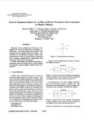
0.64 ’<br />
0.9..<br />
0.8-<br />
0.7-<br />
0.7 0.8 0;9 1 .o<br />
Fig. 10. Torque reduction as a function <strong>of</strong> flux-reduction coefficient.<br />
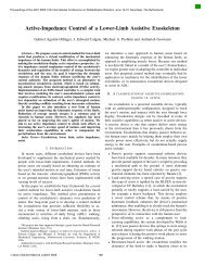
T-<br />
0.67-<br />
1 :<br />
0.6 0.8 I .o<br />
5<br />
Fig. 11. Torque reduction as a function <strong>of</strong> the saturation coefficient.<br />
even during freewheeling or braking. The inverter device<br />
ratings that are <strong>of</strong> interest are the forward voltage blocking<br />
and the current rating. Generally, current ratings <strong>of</strong> interest<br />
are the continuous and the pulsed values. When the commanded<br />
torque <strong>of</strong> the servo is much larger than the actual<br />
value, i.e., during startup, the peak current rating <strong>of</strong> the<br />
motor can be demanded for extended periods <strong>of</strong> time. The<br />
BDCM requires a trapezoidal current, and the continuous<br />
rating <strong>of</strong> the inverter should be the peak <strong>of</strong> this waveform.<br />
On the other hand, the PMSM requires sinusoidal currents.<br />
However, for a zero speed command, dc currents flow in the<br />
PMSM (which can also be considered to be the ac <strong>of</strong> zero<br />
frequency). Hence, the continuous rating <strong>of</strong> the inverter must<br />
be the peak <strong>of</strong> the sinusoid. Current control in a current-regulated<br />
inverter is only maintained if there is sufficient voltage<br />
differential between the dc bus and the back emf <strong>of</strong> the<br />
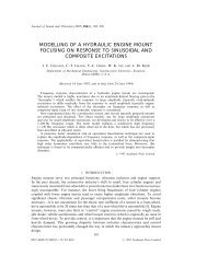
CL<br />
0.7 0.8 0.9 I .o<br />
a<br />
Fig. 12. Torque reduction as a function <strong>of</strong> the flux-reduction coefficient.<br />
machine. Let a given inverter have a continuous current<br />
rating <strong>of</strong> I,,, and suppose it can tolerate a maximum back<br />
emf <strong>of</strong> Ep for proper current control. Then, when driving a<br />
PMSM, the maximum possible output is<br />
3 E, I, /J2J2 = 3 E, Zp 12.<br />
If it drives a BDCM, then the output is 2 E,, Zp. Therefore, a<br />
given current-regulated inverter (ramp comparison or hysteresis),<br />
with a continuous current rating <strong>of</strong> I,, can drive a<br />
BDCM <strong>of</strong> 33% higher power output than a PMSM. This<br />
value would be reduced somewhat by the increased core<br />
losses <strong>of</strong> BDCM, as will be discussed in the next section.<br />
The rectifier must be capable <strong>of</strong> holding the dc bus voltage<br />
within limits while the inverter is supplying its peak current<br />
capability. Since in this section the comparison was done on<br />
the basis <strong>of</strong> the inverter supplying the same peak current, the<br />
rating <strong>of</strong> the rectifier is the same whether a BDCM or a<br />
PMSM is used.<br />
Losses and Thermal Capability<br />
The electrical losses in a PM machine takes two forms:<br />
copper and core. Copper losses are fairly easy to compute,<br />
given the stator resistance and the magnitude and shape <strong>of</strong> the<br />
stator current. Core losses are much more difficult to calculate<br />
because they are dependent on the molecular <strong>characteristics</strong><br />
<strong>of</strong> the steel, whether the <strong>magnet</strong>ization is pulsating or<br />
rotating, and is quite heavily dependent on the ability <strong>of</strong> the<br />
manufacturer to prevent burrs that form short circuits between<br />
adjacent laminations. The core losses can be divided<br />
into hysteresis and eddy currents. For sinusoidal excitation,<br />
the hysteresis loss is given by<br />
Ph = K, fBxWlkg ( 12)<br />
where x lies between 0.5 and 2.3 and is normally around 2.<br />
The eddy current loss is given by<br />
P, = K, f 2B2. (13)<br />
In the PMSM, the flux density is sinusoidal, whereas in the<br />
BDCM, it is trapezoidal. Each <strong>of</strong> the harmonics <strong>of</strong> the flux