Application characteristics of permanent magnet ... - Colgate
Application characteristics of permanent magnet ... - Colgate
Application characteristics of permanent magnet ... - Colgate

Create successful ePaper yourself
Turn your PDF publications into a flip-book with our unique Google optimized e-Paper software.
PILLAY AND KRISHNAN: APPLICATION CHARACTERISTICS OF dc MOTORS FOR SERVO DRIVES 99 1<br />
significant, with the d axis reluctance normally being larger<br />
than that <strong>of</strong> the q axis. This is so because whereas in the<br />
<strong>magnet</strong>ic circuit on the q axis there is only iron, a part <strong>of</strong> the<br />
<strong>magnet</strong>ic circuit on the d axis consists <strong>of</strong> the <strong>magnet</strong>, which<br />
has a permeability approximately that <strong>of</strong> air. This increases<br />
the d-axis reluctance, hence, reducing its inductance. This<br />
leads to the reluctance torque being <strong>of</strong> a negative sign to that<br />
<strong>of</strong> a wound rotor salient pole synchronous motor as shown in<br />
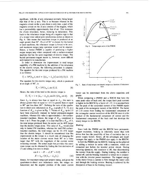
Fig. 6. This means that maximum torque is produced at an<br />
angle greater than 90". If a 6 <strong>of</strong> 90" is chosen for the buried<br />
or inset machines, the reluctance torque is forced to be zero,<br />
and maximum torque/amp operation would not be attained.<br />
Hence, a buried PMSM is capable <strong>of</strong> producing a higher<br />
output torque/amp when compared with a surface-mounted<br />
machine that has the same magnitude <strong>of</strong> electric torque. The<br />
buried <strong>permanent</strong>-<strong>magnet</strong> motor is, however, more difficult<br />
and expensive to manufacture.<br />
In order to determine the improvement in total torque<br />
capability <strong>of</strong> a PM machine by the addition <strong>of</strong> the reluctance<br />
to the electric torque, the following procedure is adopted.<br />
The equation for the total torque produced by a PM machine<br />
is as follows:<br />
The equation for the electric torque only, which is produced<br />
at an angle <strong>of</strong> 90", is<br />
T, = 3P(Xafi,sin6)/2. (8)<br />
Hence, the ratio <strong>of</strong> the total to the electric torque is<br />
Tf/T,= 1 + (Ld- L,)i,sin26/(2Xafsin6). (9)<br />
Since L, is always less than or equal to L,, this ratio is<br />
always greater than or equal to 1 if 6 is greater than or equal<br />
to 90" and less than 180". Defining the ratio <strong>of</strong> the quadrature<br />
to direct axis inductances as Kqd, a graph <strong>of</strong> T, / T, as a<br />
function <strong>of</strong> K,, is given in Fig. 7. Values <strong>of</strong> Kqd up to 2.5<br />
have been practically realized in buried <strong>permanent</strong>-<strong>magnet</strong><br />
machines, whereas this value is approximately 1 for surfacemounted<br />
machines. Hence, the range <strong>of</strong> K,, considered is<br />
from 1 to 3. From the graph, it is clear that for a K,, <strong>of</strong> 3,<br />
the total torque produced from the motor can be 40% larger<br />
than the electric torque alone. This value <strong>of</strong> Kqd would exist<br />
only in buried PM machines, whereas for inset PM surfacemounted<br />
machines, the total torque can be 10-15% larger<br />
than the electric torque. It should be remembered that this<br />
improvement in the torque is a result only <strong>of</strong> changing the<br />
location <strong>of</strong> the stator current vector from 90" to a value<br />
larger than 90" with the magnitude <strong>of</strong> the current vector<br />
remaining constant. The actual angle that provides this maximum<br />
torque can be obtained by finding the first derivative <strong>of</strong><br />
(7) and setting it to zero to obtain<br />
COS 6 = -X - J(X2 + 0.5)<br />
X = Xaf/(4(~, - ~q)is)* ( 10)<br />
Hence, for maximum torque per ampere rating, and given the<br />
quadrature-to-direct axis inductance ratio, the torque enhancement<br />
and the angular position <strong>of</strong> the stator current<br />
a,<br />
U<br />
0<br />
Y<br />
L.0<br />
U<br />
50<br />
I<br />
total<br />
Fig. 6. Torque angle curve <strong>of</strong> the PMSM.<br />
reluctance<br />
,I 2<br />
3 4<br />
Kqd<br />
Fig. 7. Ratio <strong>of</strong> total torque over electric torque as a function <strong>of</strong> inductance<br />
ratio.<br />
vector can be determined from the above equations and<br />
graphs.<br />
When comparing a PMSM and a BDCM that have the<br />
same peak value <strong>of</strong> back emf, the torque/(unit peak current)<br />
is higher in the BDCM by a factor <strong>of</strong> 1.33. It is assumed here<br />
that the peak <strong>of</strong> the sinusoidal current <strong>of</strong> the PMSM equals<br />
the peak <strong>of</strong> the rectangular current <strong>of</strong> the BDCM. The factor<br />
<strong>of</strong> 1.33 comes from finding the fundamental component <strong>of</strong><br />
the rectangular current waveform <strong>of</strong> the BDCM since it is the<br />
product <strong>of</strong> the fundamental component <strong>of</strong> current and the<br />
fundamental component <strong>of</strong> the back emf that develops the<br />
steady torque in the BDCM.<br />
Braking<br />
Since both the PMSM and the BDCM have <strong>permanent</strong><strong>magnet</strong><br />
excitation, braking in inherently easier than with<br />
drives that face the possibility <strong>of</strong> loss <strong>of</strong> excitation due to a<br />
power supply failure. Hence, all the advantages and disadvantages<br />
that apply to the PMSM also apply to the BDCM.<br />
In both the PMSM and the BDCM, braking can be achieved<br />
by adding a resistor in series with a transistor, which are<br />
connected just before the inverter power circuit. During<br />
motoring operation, this transistor is <strong>of</strong>f, thus disconnecting<br />
the resistor from the supply. During braking, the rectifier is<br />
turned <strong>of</strong>f, and the braking transistor is turned on in conjunction<br />
with the inverter power transistors. The trapped energy<br />
in the motor forces a current to flow through the motor coils<br />
and through the braking resistor. Braking is achieved by the<br />
dissipation <strong>of</strong> heat in the braking resistor.