Application characteristics of permanent magnet ... - Colgate
Application characteristics of permanent magnet ... - Colgate
Application characteristics of permanent magnet ... - Colgate

You also want an ePaper? Increase the reach of your titles
YUMPU automatically turns print PDFs into web optimized ePapers that Google loves.
990 IEEE TRANSACTIONS ON INDUSTRY APPLICATIONS, VOL. 21, NO. 5, SEPTEMBERIOCTOBER 1991<br />
O0 270' 540'<br />
(a)<br />
(b)<br />
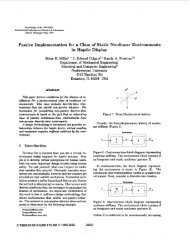
Fig. 4. Vector diagram <strong>of</strong> the PMSM during (a) constant flux and (b)<br />
flux-weakening operation.<br />
where V is the dc bus voltage, X,, X, are the stator d, q<br />
axis reactances, id, i, are the stator d, q axis currents, we is<br />
the inverter frequency, and Xu, is the mutual flux linkage<br />
between the rotor and stator due to the <strong>magnet</strong>. By setting<br />
i, = 0 and id equal to the continuous current rating <strong>of</strong> the<br />
machine, the inverter frequency and, hence, motor speed can<br />
then be determined. Since the motor is locked in at the<br />
synchronous speed, the actual maximum motor speed is given<br />
by we/P, where P is the number <strong>of</strong> pole pairs. For typical<br />
PM motor parameters, it has been found that [15] around 1.5<br />
times rated speed can be attained. In practice, it would be<br />
difficult to force is to operate at 180" to the <strong>magnet</strong> flux, and<br />
the practical maximum speed would be less than that obtained<br />
in (5).<br />
The above discussion applies equally well to the PMSM<br />
and the BDCM. The practical limitation on the maximum<br />
speed is obtained when the back emf <strong>of</strong> each machine becomes<br />
equal to that <strong>of</strong> the dc bus. Because <strong>of</strong> the difference<br />
in the waveshape <strong>of</strong> the back emf <strong>of</strong> the PMSM and the<br />
BDCM, the voltdrop that is available to force current flow is<br />
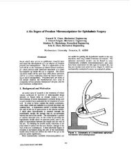
different in each machine in a given period, as shown in Fig.<br />
5. Fig. 5(a) shows the desired current relative to the back<br />
emf in order to obtain the maximum speed in the PMSM. At<br />
this operating point, the peak <strong>of</strong> the back emf is equal to that<br />
<strong>of</strong> dc bus. In the BDCM, on the other hand, current can only<br />
be forced into the motor when the back emf is less than the<br />
dc bus voltage, as shown in Fig. 5(b). Assuming that the<br />
forced current is rectangular in shape, with a peak equal to<br />
the rated value <strong>of</strong> the BDCM, it is possible to find the<br />
fundamental component <strong>of</strong> this current, which becomes id in<br />
(5) with i, = 0. Comparing a PMSM and a BDCM with the<br />
same parameters, but taking into account the current waveforms<br />
shown in Fig. 5, from (5), it can be shown that<br />
@eP /weB = ('<strong>of</strong> - 'didB)/( 'uf - LdidP) = 1*46 (6)<br />
for the motor parameters given in Appendix I. oep and oeB<br />
are the maximum PMSM and BDCM synchronous speeds,<br />
Fig. 5.<br />
I<br />
(b)<br />
(a) PMSM back emf and current waveforms and (b) BDCM<br />
waveforms during flux-weakening operation.<br />
whereas id, and idB are the direct axis currents <strong>of</strong> the<br />
PMSM and BDCM, respectively. Therefore, the speed range<br />
<strong>of</strong> a PMSM would be higher than that <strong>of</strong> a BDCM <strong>of</strong> the<br />
same parameters. The speed range <strong>of</strong> a <strong>permanent</strong>-<strong>magnet</strong><br />
machine therefore depends on the motor parameters, its<br />
current rating, the back emf waveform, and the maximum<br />
output voltage from the inverter.<br />
Torque Per Unit Current<br />
Very <strong>of</strong>ten, servo motor drives are operated to produce the<br />
maximum torque per unit current out <strong>of</strong> the machine. This is<br />
done because by minimizing the input current for a given<br />
torque, the copper, inverter, and rectifier losses are minimized.<br />
In addition, lower current ratings <strong>of</strong> the inverter and<br />
rectifier are needed for a given output; this reduces the<br />
overall cost <strong>of</strong> the system.<br />
The torque-angle curve <strong>of</strong> a PM machine is shown in Fig.<br />
6. The total motor torque consists <strong>of</strong> electric and reluctance<br />
torque components. The electric torque is produced as a<br />
result <strong>of</strong> the interaction <strong>of</strong> the stator current with the airgap<br />
flux while the reluctance torque is produced as a result <strong>of</strong><br />
reluctance variation due to rotor saliency. As shown in the<br />
vector diagram <strong>of</strong> Fig. 4, the d axis is chosen to be aligned<br />
along the <strong>magnet</strong> axis. The permeability <strong>of</strong> the <strong>magnet</strong> in the<br />
d axis is approximately that <strong>of</strong> air. If the length <strong>of</strong> the airgap<br />
on the quadrature axis is equal to that <strong>of</strong> the <strong>magnet</strong> plus air<br />
gap on the direct axis, then there is no appreciable reluctance<br />
difference between the d and q axes. Hence, the reluctance<br />
torque is approximately zero, and the total motor torque is<br />
equal to the electric torque only, where the maximum is<br />
produced at a 6 <strong>of</strong> 90°, i.e., when is is perpendicular to the<br />
rotor flux. This is normally true <strong>of</strong> projecting surface-mounted<br />
machines. In buried <strong>permanent</strong>-<strong>magnet</strong> machines, however,<br />
the reluctance variation between the d and q axes can be