Application characteristics of permanent magnet ... - Colgate
Application characteristics of permanent magnet ... - Colgate
Application characteristics of permanent magnet ... - Colgate

You also want an ePaper? Increase the reach of your titles
YUMPU automatically turns print PDFs into web optimized ePapers that Google loves.
PILLAY AND KRISHNAN: APPLICATION CHARACTERISTICS OF dc MOTORS FOR SERVO DRIVES 989<br />
-<br />
TI,TZ,T3,T4,TS,Th<br />
I<br />
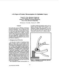
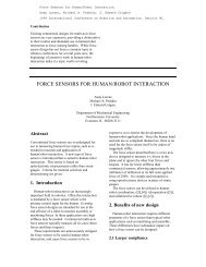
Fig. 3.<br />
PMSM or BDCM drive system.<br />
are equal. Then, the relative power densities would be determined<br />
by the copper losses. The power output <strong>of</strong> these two<br />
machines is compared based on the equality <strong>of</strong> copper losses.<br />
In the PMSM, sinusoidal currents <strong>of</strong> low harmonic content<br />
are obtainable from hysteresis or PWM current controllers<br />
such that the copper losses are essentially determined by the<br />
fundamental component <strong>of</strong> current. If the peak current is I,, ,<br />
then the RMS current is Zpl/d2, and the machine copper<br />
losses are given by 3(Zpl /J2)2R,, where R, is the phase-A<br />
resistance.<br />
In the case <strong>of</strong> the BDCM that requires trapezoidal currents<br />
for constant torque, the losses are given by 3 (J21p2/<br />
J3)2R,, where Zp2 is the peak <strong>of</strong> the trapezoidal current.<br />
Hence, assuming that the core losses <strong>of</strong> the two machines are<br />
equal and the power density is determined by the copper<br />
losses<br />
3(zpl /t'2)2R, = 3(J21p2 /J3)2R, (1)<br />
Zpl /J2 = J2Zp2 /J3<br />
(2)<br />
I,, = 2Zp2 /J3 = 1 . 15Zp2.<br />
(3)<br />
Now the ratio <strong>of</strong> the BDCM output power to the PMSM<br />
output power is given by<br />
2EpZp2 /(3EpZPl/J2J2 = 4EpJ3Zpl /6EpZpl = 1.15 (4)<br />
that is, the BDCM is capable <strong>of</strong> supplying 15% more power<br />
than the PMSM from the same frame size, that is, the power<br />
density can be 15% larger, provided the core losses are<br />
equal.<br />
Torque to Inertia Ratio<br />
Since it is possible to get 15% more power out <strong>of</strong> the<br />
BDCM, it is also possible to obtain 15% more electric torque<br />
if they have the same rated speeds. If their rotor inertias are<br />
equal, then the torque-to-inertia ratio <strong>of</strong> the BDCM can be as<br />
much as 15% higher than the PMSM. It should be noted that<br />
the PMSM and BDCM have a higher torque-to-inertia ratio<br />
than the induction motor [2].<br />
Speed Range<br />
Servo drives operate in the constant torque mode <strong>of</strong> operation<br />
from zero to rated speed and in the constant power mode<br />
<strong>of</strong> operation from rated to maximum speed. In the constant<br />
torque region, the air gap flux is held constant, whereas in<br />
the constant power region, the air gap flux is weakened by<br />
applying a stator flux in opposition to the rotor <strong>magnet</strong> flux.<br />
This is also known as armature reaction and is illustrated in<br />
Fig. 4.<br />
During constant flux operation, is is maintained at 90" to<br />
the rotor flux as shown in Fig. 4. In the flux-weakening<br />
mode, is is maintained at an angle greater than 90" from the<br />
rotor flux. This allows a component <strong>of</strong> stator current id to<br />
create a stator flux that opposes the rotor flux, and hence,<br />
air-gap flux weakening is obtained.<br />
The magnitude <strong>of</strong> is, which is the vector sum <strong>of</strong> the direct<br />
and quadrature axis stator currents, has a fixed continuous<br />
rating during steady-state operation. This can be exceeded for<br />
short periods <strong>of</strong> time during transients. If a higher speed<br />
range is required, a larger negative id is needed in order to<br />
reduce the air-gap flux and i, should be lowered in order to<br />
ensure that the continuous rating <strong>of</strong> is is not exceeded. The<br />
speed capability <strong>of</strong> a <strong>permanent</strong> <strong>magnet</strong> motor drive when<br />
this method <strong>of</strong> flux weakening is used can be determined<br />
from the two axis equations as follows [14]:<br />
(0.636V/X,)2 = ii + ( Xd(id + W~A,~/X,)/X,)~ (5)