Application characteristics of permanent magnet ... - Colgate
Application characteristics of permanent magnet ... - Colgate
Application characteristics of permanent magnet ... - Colgate

Create successful ePaper yourself
Turn your PDF publications into a flip-book with our unique Google optimized e-Paper software.
~<br />
988 IEEE TRANSACTIONS ON INDUSTRY APPLICATIONS, VOL. 21, NO. 5, SEPTEMBERIOCTOBER 1991<br />
addition, an epoxy glue is used to fix the <strong>magnet</strong>s to the rotor<br />
surface in the inset and projecting surface-mounted machines.<br />
This implies that the mechanical strength <strong>of</strong> the surface<br />
mounted machines is only as good as that <strong>of</strong> the epoxy glue,<br />
assuming no retaining sleeve is used; hence, buried PM<br />
machines are more robust and tend to be used for high-speed<br />
applications. In addition, the direct and quadrature axis inductances<br />
<strong>of</strong> the projecting surface-mounted PM machines<br />
are approximately equal. This is because the length <strong>of</strong> the<br />
airgap is equal to that <strong>of</strong> the <strong>magnet</strong>, which has a permeability<br />
approximately that <strong>of</strong> air. This results in the direct and<br />
quadrature axis reluctances and, hence, inductances being<br />
approximately equal. The opposite is true, however, in the<br />
buried PM machine. Here, the quadrature axis inductance<br />
can be much larger than that <strong>of</strong> the direct axis since, although<br />
the length <strong>of</strong> the airgap is the same, the space occupied by<br />
the <strong>magnet</strong> in the direct axis is occupied by iron (and not air)<br />
in the quadrature axis. The difference between the quadrature<br />
and direct axis inductances in inset PM machines lies between<br />
that <strong>of</strong> the buried and projecting surface-mounted<br />
machines. This means that in addition to the electric torque, a<br />
reluctance torque exists in buried and inset PM machines.<br />
This torque can be used to increase the torque/current rating<br />
as discussed later.<br />
Although most machines on the market are <strong>of</strong> the radial<br />
field design, recent research [2] indicates that the axial field<br />
has some advantages over the conventional radial field designs,<br />
especially in terms <strong>of</strong> power density and torque-to-inertia<br />
ratio.<br />
Differences Between the PMSM and BDCM<br />
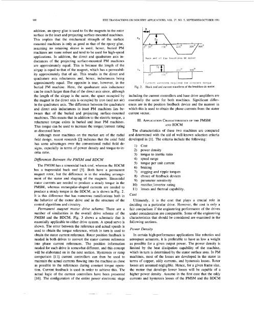
The PMSM has a sinusoidal back emf, whereas the BDCM<br />
has a trapezoidal back emf [5]. Both have a <strong>permanent</strong><br />
<strong>magnet</strong> rotor, but the difference is in the winding arrangement<br />
<strong>of</strong> the stator and shaping <strong>of</strong> the <strong>magnet</strong>s. Sinusoidal<br />
stator currents are needed to produce a steady torque in the<br />
PMSM, whereas rectangular-shaped currents are needed to<br />
produce a steady torque in the BDCM, as is shown in Fig. 2.<br />
It is this difference that has numerous ramifications both in<br />
the behavior <strong>of</strong> the motor drive and in the structure <strong>of</strong> the<br />
control algorithms and circuitry.<br />
Permanent <strong>magnet</strong> motor drive scheme: There are a<br />
number <strong>of</strong> similarities in the overall drive scheme <strong>of</strong> the<br />
PMSM and the BDCM. Fig. 3 shows a schematic that is<br />
essentially applicable to either drive system. A speed servo is<br />
shown. The error between the reference and actual speeds is<br />
used to obtain the torque reference, which in turn is used to<br />
obtain the stator current reference. Rotor position feedback is<br />
needed in both drives to convert the stator current reference<br />
into phase current references. The position information<br />
needed for each drive is somewhat different, and this concept<br />
will be elaborated on in the next section. Hysteresis or ramp<br />
comparison [ll] current controllers can then be used to<br />
maintain the actual currents flowing into the machine as close<br />
as possible to the references during constant torque operation.<br />
Current feedback is used in order to achieve this. The<br />
actual logic <strong>of</strong> the current controllers have been presented<br />
[16]. The configuration <strong>of</strong> the entire power electronic stage<br />
Back emf <strong>of</strong> the brushless DC motor<br />
I<br />
I CdrreTc waveform required for constant torque<br />
Fig. 2. Block emf and current waveform <strong>of</strong> the brushless dc motor.<br />
including the current controllers and base drive amplifiers are<br />
essentially the same for both machines. Significant differences<br />
are in the position feedback device and the manner in<br />
which this is used to obtain the phase currents from the stator<br />
current vector.<br />
111. APPLICATION CHARACTERISTICS OF THE PMSM<br />
AND BDCM<br />
The <strong>characteristics</strong> <strong>of</strong> these two machines are compared<br />
and determined with the aid <strong>of</strong> well-known selection criteria<br />
developed in [l]. The criteria include the following:<br />
cost<br />
power density<br />
torque to inertia ratio<br />
speed range<br />
torque per unit current<br />
braking<br />
cogging and ripple torques<br />
choice <strong>of</strong> feedback devices<br />
parameter sensitivity<br />
rectifier/inverter rating<br />
losses and thermal capability.<br />
Ultimately, it is the cost that plays a crucial role in<br />
deciding on a particular drive. However, the cost is only a<br />
fair comparison if the engineering performance <strong>of</strong> the drives<br />
under consideration are comparable. Some <strong>of</strong> the engineering<br />
<strong>characteristics</strong> that should be considered are examined in the<br />
following sections.<br />
Power Density<br />
In certain high-performance applications like robotics and<br />
aerospace actuators, it is preferable to have as low a weight<br />
as possible for a given output power. The power density is<br />
limited by the heat dissipation capability <strong>of</strong> the machine,<br />
which in turn is determined by the stator surface area. In PM<br />
machines, most <strong>of</strong> the losses are developed in the stator in<br />
terms <strong>of</strong> copper, eddy currents, and hysteresis losses. Rotor<br />
losses are assumed negligible. Hence, for a given frame size,<br />
the motor that develops lower losses will be capable <strong>of</strong> a<br />
higher power density. Assume in the first case that the eddy<br />
currents and hysteresis losses <strong>of</strong> the PMSM and the BDCM