Application characteristics of permanent magnet ... - Colgate
Application characteristics of permanent magnet ... - Colgate
Application characteristics of permanent magnet ... - Colgate

Create successful ePaper yourself
Turn your PDF publications into a flip-book with our unique Google optimized e-Paper software.
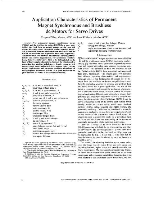
986 IEEE TRANSACTIONS ON INDUSTRY APPLICATIONS, VOL. 21, NO. 5, SEPTEMBERIOCTOBER 1991<br />
<strong>Application</strong> Characteristics <strong>of</strong> Permanent<br />
Magnet Synchronous and Brushless<br />
dc Motors for Servo Drives<br />
Pragasen Pillay, Member, IEEE, and Ramu Krishnan, Member, IEEE<br />
Abstract-The <strong>permanent</strong> <strong>magnet</strong> synchronous motor<br />
(PMSM) and the brushless dc motor (BDCM) have many similarities;<br />
they both have <strong>permanent</strong> <strong>magnet</strong>s on the rotor and<br />
require alternating stator currents to produce constant torque.<br />
The difference in these two machines is that the PMSM and the<br />
BDCM has sinusoidal and trapezoidal back emfs, respectively.<br />
This means these two machines have different operating <strong>characteristics</strong><br />
and control requirements. For application considerations,<br />
these two motor drives have to be differentiated on the<br />
basis <strong>of</strong> known engineering criteria. Some <strong>of</strong> the criteria used to<br />
assess these two machines include power density, torque per unit<br />
current, speed range, feedback devices, inverter rating, cogging<br />
torque, ripple torque, and parameter sensitivity. Guidelines for<br />
the appropriate machine to be used for a given application are<br />
given based on the results <strong>of</strong> the criteria listed above.<br />
vd* 'q<br />
V<br />
'"r<br />
'"e<br />
NOMENCLATURE<br />
a, b, and c phase back emfs, V<br />
peak value <strong>of</strong> back emf, V<br />
a, b, and c phase currents, A<br />
d and q axis stator currents, A<br />
peak value <strong>of</strong> current, A<br />
vector sum <strong>of</strong> d and q axis currents, A<br />
stator d, q inductances, H<br />
derivative operator<br />
number <strong>of</strong> pole pairs<br />
stator resistance, a<br />
electric torque, N-m<br />
load torque, N-m<br />
total motor torque, N-m<br />
d and q axis stator voltages<br />
dc bus voltage, V<br />
stator d, q reactances,<br />
angle between <strong>magnet</strong> flux and is, rad<br />
rotor speed, rad/s<br />
synchronous speed, rad/s<br />
mutual flux linkage between rotor and stator due<br />
to <strong>magnet</strong>, Wb-turn<br />
Paper IPCSD 91-24, approved by the Industrial Drives Committee <strong>of</strong> the<br />
IEEE Industry <strong>Application</strong>s Society for presentation at the 1987 Industry<br />
<strong>Application</strong>s Society Annual Meeting, Atlanta, GA, October 18-23.<br />
Manuscript released for publication February 26, 1991,<br />
P. Pillay is with the Department <strong>of</strong> Electrical Engineering, University <strong>of</strong><br />
New Orleans, Lakefront, LA 70148.<br />
R. Krishnan is with the Electrical Engineering Department, Virginia<br />
Polytechnic Institute and State University, Blacksburg, VA 24061.<br />
IEEE Log Number 9100932.<br />
hd, hq<br />
hnl<br />
er<br />
stator d and q axis flux linkage, Wb-turn<br />
air gap flux linkage, Wb-turn<br />
angle between stator phase A and the rotor, rad<br />
superscript indicating reference value<br />
I, INTRODUCTION<br />
HE PERMANENT <strong>magnet</strong> synchronous motor (PMSM)<br />
T and the brushless dc motor (BDCM) have many similarities<br />
[l], [2]; they both have a <strong>permanent</strong> <strong>magnet</strong> (PM) on the<br />
rotor and require alternating stator currents to produce constant<br />
torque. The difference in these two machines is that<br />
the PMSM and the BDCM have sinusoidal and trapezoidal<br />
back emfs, respectively. This means these two machines<br />
have different operating <strong>characteristics</strong> and requirements.<br />
Although some <strong>of</strong> the fundamental differences [ 11 -[5] between<br />
these two machines are known, no guidelines exist to<br />
help the application engineer to compare and contrast these<br />
two servo drives for a given application. The aim <strong>of</strong> this<br />
paper is to compare and present the application <strong>characteristics</strong><br />
<strong>of</strong> these two motor drives. Selection criteria for comparing<br />
and contrasting different motor drives have already been<br />
presented [l]. This paper uses these criteria to compare and<br />
assess the <strong>characteristics</strong> <strong>of</strong> the PMSM and BDCM drives for<br />
servo applications. Some <strong>of</strong> the criteria used include power<br />
density, torque per current rating, speed range, feedback<br />
devices, inverter rating, cogging and ripple torques, and<br />
parameter sensitivity. Guidelines are developed to select the<br />
appropriate machine to be used for a given application based<br />
on the results <strong>of</strong> the comparison criteria listed above. An<br />
attempt is made to present the results on a normalized basis<br />
as far as possible so that the applicability <strong>of</strong> the results are<br />
essentially independent <strong>of</strong> the particular motor rating.<br />
There are a variety <strong>of</strong> ac servo drives on the market<br />
[1]-[5] competing with both the dc brush machine and other<br />
ac servo drives. The selection process <strong>of</strong> a servo drive for a<br />
particular application in the fractional to 30-hp range can<br />
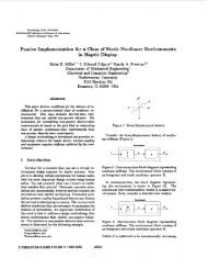
be represented by Fig. 1. From Fig. 1, it is clear that the<br />
first decision to be made is whether to use a dc brush or a<br />
brushless servo.<br />
The reasons for choosing brushless servo motor drives<br />
over the brush type dc motor drives are well known and<br />
include robustness, higher torque and speed bandwidths, and<br />
lower maintenance. The mechanical commutator and brushes<br />
<strong>of</strong> the dc motor also enforce severe limitations on its maximum<br />
speed and overcurrent capabilities. Assuming that it has<br />
been decided to use a brushless servo motor drive. the next<br />
0093-9994/91/0900-0986$01.00 0 1991 IEEE<br />
QXA IEEE TRANSACTIONS ON INDUSTRY APPLICATIONS, VOL. 21, NO. 5, SEPTEMBERIOCTOBER 1991
PILLAY AND KRISHNAN: APPLICATION CHARACTERISTICS OF dc MOTORS FOR SERVO DRIVES 987<br />
DC BRUSH<br />
APPLICATION<br />
AC MOTORS<br />
BRUSHLESS<br />
i+7<br />
PERMANENT MAGNET INDUCTION<br />
PMSM<br />
f-11<br />
SWITCHED RELUCTANCE<br />
BDCM<br />
Fig. 1. Motor selection procedure.<br />
decision to make is whether to use an ac or a switched<br />
reluctance motor. The switched reluctance motor is inherently<br />
a pulsating torque machine, although some work has<br />
been done in an attempt to reduce the torque ripple. Hence, if<br />
a reasonably smooth output torque is required, an induction<br />
or <strong>permanent</strong> <strong>magnet</strong> machine is to be preferred over the<br />
switched reluctance motor. The next decision to be made,<br />
then, is whether to use an induction or a PM motor.<br />
The <strong>permanent</strong> <strong>magnet</strong> motor drives have the following<br />
advantages over the induction motor (IM) drive [1]-[lo]:<br />
The rare earth and neodymium boron PM machine has<br />
a lower inertia when compared with an IM because <strong>of</strong><br />
the absence <strong>of</strong> a rotor cage; this makes for a faster<br />
response for a given electric torque. In other words,<br />
the torque to inertia ratio <strong>of</strong> these PM machines is<br />
higher.<br />
The PM machine has a higher efficiency than an<br />
induction machine. This is primarily because there are<br />
negligible rotor losses in <strong>permanent</strong> <strong>magnet</strong> machines;<br />
the rotor losses in the IM, however, can be considerable,<br />
depending on the operating slip. This discussion<br />
is applicable to constant flux operation.<br />
The IM requires a source <strong>of</strong> <strong>magnet</strong>izing current for<br />
excitation. The PM machine already has the excitation<br />
in the form <strong>of</strong> the rotor <strong>magnet</strong>.<br />
The need for <strong>magnet</strong>izing current and the fact that the<br />
IM has a lower efficiency necessitates a larger rated<br />
rectifier and inverter for the IM than for a PM machine<br />
<strong>of</strong> the same output capacity.<br />
The PM machine is smaller in size than an induction<br />
motor <strong>of</strong> the same capacity. Hence, it is advantageous<br />
to use PM machines, especially where space is a<br />
serious limitation. In addition, the <strong>permanent</strong> <strong>magnet</strong><br />
machine weight less. In other words, the power density<br />
<strong>of</strong> <strong>permanent</strong> <strong>magnet</strong> machines is higher.<br />
The rotor losses in a PM machine are negligible<br />
compared with those in the induction motor. A problem<br />
that has been encountered in the machine tools<br />
industry is the transferal <strong>of</strong> these rotor losses in the<br />
form <strong>of</strong> heat to the machine tools and work pieces,<br />
thus affecting the machining operation. This problem<br />
is avoided in <strong>permanent</strong> <strong>magnet</strong> machines.<br />
The induction motor drive has the following advantages<br />
over <strong>permanent</strong> <strong>magnet</strong> motor drives [2]:<br />
Larger field weakening range and ease <strong>of</strong> control in<br />
that region<br />
lower cogging torques<br />
less expensive feedback transducers such as an incremental<br />
rotor position encoder for the IM instead <strong>of</strong> an<br />
absolute position encoder that is required by the <strong>permanent</strong><br />
<strong>magnet</strong> motor drives<br />
lower cost<br />
much higher rotor operating temperatures that are<br />
allowed in induction motors than in PM motors.<br />
Depending on the application, a choice is made between an<br />
IM or ac PM motor drive if the dc brush and switched<br />
reluctance servos are excluded. If the choice is narrowed to<br />
an ac <strong>permanent</strong> <strong>magnet</strong> motor drive, then there are hardly<br />
any guidelines to differentiate the available <strong>permanent</strong> <strong>magnet</strong><br />
motor drives, namely, the PMSM drive and the BDCM<br />
drive. This paper concerns itself mainly with this aspect <strong>of</strong><br />
the problem.<br />
The paper is organized as follows: The similarities and<br />
differences between the PMSM and BDCM and the drive<br />
strategy are discussed in Section 11. Power density, torque to<br />
inertia ratio, speed range, torque per unit current, braking,<br />
parameter sensitivity, and other criteria are used to compare<br />
and contrast the PM motor drives in Section 111. Conclusions<br />
are given in Section IV.<br />
11. DESCRIPTION OF THE PMSM AND BDCM<br />
Similarities Between the PMSM and BDCM<br />
The PMSM owes its origin to the replacement <strong>of</strong> the<br />
exciter <strong>of</strong> the wound rotor synchronous machine, which<br />
included a field coil, brushes, and slip rings with a <strong>permanent</strong><br />
<strong>magnet</strong>. A distinguishing feature <strong>of</strong> the PMSM is that it<br />
generates a sinusoidal back emf just like an induction motor<br />
or wound rotor synchronous motor; in fact, the stator <strong>of</strong> the<br />
PMSM is quite similar to that <strong>of</strong> the induction machine.<br />
The BDCM owes its origin to an attempt to invert the<br />
brush dc machine to remove the need for the commutator and<br />
brush gear. The commutator in the brush dc machine converts<br />
the input dc current into approximately rectangular<br />
shaped currents <strong>of</strong> variable frequency. By applying this rectangular-shaped<br />
current directly to the stator <strong>of</strong> the BDCM<br />
and transferring the field excitation to the rotor in the form <strong>of</strong><br />
a <strong>permanent</strong> <strong>magnet</strong>, an inversion <strong>of</strong> the brush dc machine<br />
has taken place with the advantage that the new inverted<br />
machine does not have a mechanical commutator and brush<br />
gear, hen& the name brushless dc machine.<br />
The <strong>magnet</strong>s in the PMSM or the BDCM can be either<br />
buried or surface mounted. In the surface-mounted machine,<br />
two variations can exist. The <strong>magnet</strong>s can be inset into the<br />
rotor or project from the surface <strong>of</strong> the rotor. These machines<br />
will be referred to as buried, inset, and projecting PM<br />
machines, respectively.<br />
Buried PM machines are more difficult to construct than<br />
either the inset or projecting surface-mounted machines. In
~<br />
988 IEEE TRANSACTIONS ON INDUSTRY APPLICATIONS, VOL. 21, NO. 5, SEPTEMBERIOCTOBER 1991<br />
addition, an epoxy glue is used to fix the <strong>magnet</strong>s to the rotor<br />
surface in the inset and projecting surface-mounted machines.<br />
This implies that the mechanical strength <strong>of</strong> the surface<br />
mounted machines is only as good as that <strong>of</strong> the epoxy glue,<br />
assuming no retaining sleeve is used; hence, buried PM<br />
machines are more robust and tend to be used for high-speed<br />
applications. In addition, the direct and quadrature axis inductances<br />
<strong>of</strong> the projecting surface-mounted PM machines<br />
are approximately equal. This is because the length <strong>of</strong> the<br />
airgap is equal to that <strong>of</strong> the <strong>magnet</strong>, which has a permeability<br />
approximately that <strong>of</strong> air. This results in the direct and<br />
quadrature axis reluctances and, hence, inductances being<br />
approximately equal. The opposite is true, however, in the<br />
buried PM machine. Here, the quadrature axis inductance<br />
can be much larger than that <strong>of</strong> the direct axis since, although<br />
the length <strong>of</strong> the airgap is the same, the space occupied by<br />
the <strong>magnet</strong> in the direct axis is occupied by iron (and not air)<br />
in the quadrature axis. The difference between the quadrature<br />
and direct axis inductances in inset PM machines lies between<br />
that <strong>of</strong> the buried and projecting surface-mounted<br />
machines. This means that in addition to the electric torque, a<br />
reluctance torque exists in buried and inset PM machines.<br />
This torque can be used to increase the torque/current rating<br />
as discussed later.<br />
Although most machines on the market are <strong>of</strong> the radial<br />
field design, recent research [2] indicates that the axial field<br />
has some advantages over the conventional radial field designs,<br />
especially in terms <strong>of</strong> power density and torque-to-inertia<br />
ratio.<br />
Differences Between the PMSM and BDCM<br />
The PMSM has a sinusoidal back emf, whereas the BDCM<br />
has a trapezoidal back emf [5]. Both have a <strong>permanent</strong><br />
<strong>magnet</strong> rotor, but the difference is in the winding arrangement<br />
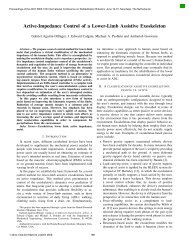
<strong>of</strong> the stator and shaping <strong>of</strong> the <strong>magnet</strong>s. Sinusoidal<br />
stator currents are needed to produce a steady torque in the<br />
PMSM, whereas rectangular-shaped currents are needed to<br />
produce a steady torque in the BDCM, as is shown in Fig. 2.<br />
It is this difference that has numerous ramifications both in<br />
the behavior <strong>of</strong> the motor drive and in the structure <strong>of</strong> the<br />
control algorithms and circuitry.<br />
Permanent <strong>magnet</strong> motor drive scheme: There are a<br />
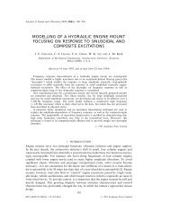
number <strong>of</strong> similarities in the overall drive scheme <strong>of</strong> the<br />
PMSM and the BDCM. Fig. 3 shows a schematic that is<br />
essentially applicable to either drive system. A speed servo is<br />
shown. The error between the reference and actual speeds is<br />
used to obtain the torque reference, which in turn is used to<br />
obtain the stator current reference. Rotor position feedback is<br />
needed in both drives to convert the stator current reference<br />
into phase current references. The position information<br />
needed for each drive is somewhat different, and this concept<br />
will be elaborated on in the next section. Hysteresis or ramp<br />
comparison [ll] current controllers can then be used to<br />
maintain the actual currents flowing into the machine as close<br />
as possible to the references during constant torque operation.<br />
Current feedback is used in order to achieve this. The<br />
actual logic <strong>of</strong> the current controllers have been presented<br />
[16]. The configuration <strong>of</strong> the entire power electronic stage<br />
Back emf <strong>of</strong> the brushless DC motor<br />
I<br />
I CdrreTc waveform required for constant torque<br />
Fig. 2. Block emf and current waveform <strong>of</strong> the brushless dc motor.<br />
including the current controllers and base drive amplifiers are<br />
essentially the same for both machines. Significant differences<br />
are in the position feedback device and the manner in<br />
which this is used to obtain the phase currents from the stator<br />
current vector.<br />
111. APPLICATION CHARACTERISTICS OF THE PMSM<br />
AND BDCM<br />
The <strong>characteristics</strong> <strong>of</strong> these two machines are compared<br />
and determined with the aid <strong>of</strong> well-known selection criteria<br />
developed in [l]. The criteria include the following:<br />
cost<br />
power density<br />
torque to inertia ratio<br />
speed range<br />
torque per unit current<br />
braking<br />
cogging and ripple torques<br />
choice <strong>of</strong> feedback devices<br />
parameter sensitivity<br />
rectifier/inverter rating<br />
losses and thermal capability.<br />
Ultimately, it is the cost that plays a crucial role in<br />
deciding on a particular drive. However, the cost is only a<br />
fair comparison if the engineering performance <strong>of</strong> the drives<br />
under consideration are comparable. Some <strong>of</strong> the engineering<br />
<strong>characteristics</strong> that should be considered are examined in the<br />
following sections.<br />
Power Density<br />
In certain high-performance applications like robotics and<br />
aerospace actuators, it is preferable to have as low a weight<br />
as possible for a given output power. The power density is<br />
limited by the heat dissipation capability <strong>of</strong> the machine,<br />
which in turn is determined by the stator surface area. In PM<br />
machines, most <strong>of</strong> the losses are developed in the stator in<br />
terms <strong>of</strong> copper, eddy currents, and hysteresis losses. Rotor<br />
losses are assumed negligible. Hence, for a given frame size,<br />
the motor that develops lower losses will be capable <strong>of</strong> a<br />
higher power density. Assume in the first case that the eddy<br />
currents and hysteresis losses <strong>of</strong> the PMSM and the BDCM
PILLAY AND KRISHNAN: APPLICATION CHARACTERISTICS OF dc MOTORS FOR SERVO DRIVES 989<br />
-<br />
TI,TZ,T3,T4,TS,Th<br />
I<br />
Fig. 3.<br />
PMSM or BDCM drive system.<br />
are equal. Then, the relative power densities would be determined<br />
by the copper losses. The power output <strong>of</strong> these two<br />
machines is compared based on the equality <strong>of</strong> copper losses.<br />
In the PMSM, sinusoidal currents <strong>of</strong> low harmonic content<br />
are obtainable from hysteresis or PWM current controllers<br />
such that the copper losses are essentially determined by the<br />
fundamental component <strong>of</strong> current. If the peak current is I,, ,<br />
then the RMS current is Zpl/d2, and the machine copper<br />
losses are given by 3(Zpl /J2)2R,, where R, is the phase-A<br />
resistance.<br />
In the case <strong>of</strong> the BDCM that requires trapezoidal currents<br />
for constant torque, the losses are given by 3 (J21p2/<br />
J3)2R,, where Zp2 is the peak <strong>of</strong> the trapezoidal current.<br />
Hence, assuming that the core losses <strong>of</strong> the two machines are<br />
equal and the power density is determined by the copper<br />
losses<br />
3(zpl /t'2)2R, = 3(J21p2 /J3)2R, (1)<br />
Zpl /J2 = J2Zp2 /J3<br />
(2)<br />
I,, = 2Zp2 /J3 = 1 . 15Zp2.<br />
(3)<br />
Now the ratio <strong>of</strong> the BDCM output power to the PMSM<br />
output power is given by<br />
2EpZp2 /(3EpZPl/J2J2 = 4EpJ3Zpl /6EpZpl = 1.15 (4)<br />
that is, the BDCM is capable <strong>of</strong> supplying 15% more power<br />
than the PMSM from the same frame size, that is, the power<br />
density can be 15% larger, provided the core losses are<br />
equal.<br />
Torque to Inertia Ratio<br />
Since it is possible to get 15% more power out <strong>of</strong> the<br />
BDCM, it is also possible to obtain 15% more electric torque<br />
if they have the same rated speeds. If their rotor inertias are<br />
equal, then the torque-to-inertia ratio <strong>of</strong> the BDCM can be as<br />
much as 15% higher than the PMSM. It should be noted that<br />
the PMSM and BDCM have a higher torque-to-inertia ratio<br />
than the induction motor [2].<br />
Speed Range<br />
Servo drives operate in the constant torque mode <strong>of</strong> operation<br />
from zero to rated speed and in the constant power mode<br />
<strong>of</strong> operation from rated to maximum speed. In the constant<br />
torque region, the air gap flux is held constant, whereas in<br />
the constant power region, the air gap flux is weakened by<br />
applying a stator flux in opposition to the rotor <strong>magnet</strong> flux.<br />
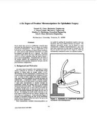
This is also known as armature reaction and is illustrated in<br />
Fig. 4.<br />
During constant flux operation, is is maintained at 90" to<br />
the rotor flux as shown in Fig. 4. In the flux-weakening<br />
mode, is is maintained at an angle greater than 90" from the<br />
rotor flux. This allows a component <strong>of</strong> stator current id to<br />
create a stator flux that opposes the rotor flux, and hence,<br />
air-gap flux weakening is obtained.<br />
The magnitude <strong>of</strong> is, which is the vector sum <strong>of</strong> the direct<br />
and quadrature axis stator currents, has a fixed continuous<br />
rating during steady-state operation. This can be exceeded for<br />
short periods <strong>of</strong> time during transients. If a higher speed<br />
range is required, a larger negative id is needed in order to<br />
reduce the air-gap flux and i, should be lowered in order to<br />
ensure that the continuous rating <strong>of</strong> is is not exceeded. The<br />
speed capability <strong>of</strong> a <strong>permanent</strong> <strong>magnet</strong> motor drive when<br />
this method <strong>of</strong> flux weakening is used can be determined<br />
from the two axis equations as follows [14]:<br />
(0.636V/X,)2 = ii + ( Xd(id + W~A,~/X,)/X,)~ (5)
990 IEEE TRANSACTIONS ON INDUSTRY APPLICATIONS, VOL. 21, NO. 5, SEPTEMBERIOCTOBER 1991<br />
O0 270' 540'<br />
(a)<br />
(b)<br />
Fig. 4. Vector diagram <strong>of</strong> the PMSM during (a) constant flux and (b)<br />
flux-weakening operation.<br />
where V is the dc bus voltage, X,, X, are the stator d, q<br />
axis reactances, id, i, are the stator d, q axis currents, we is<br />
the inverter frequency, and Xu, is the mutual flux linkage<br />
between the rotor and stator due to the <strong>magnet</strong>. By setting<br />
i, = 0 and id equal to the continuous current rating <strong>of</strong> the<br />
machine, the inverter frequency and, hence, motor speed can<br />
then be determined. Since the motor is locked in at the<br />
synchronous speed, the actual maximum motor speed is given<br />
by we/P, where P is the number <strong>of</strong> pole pairs. For typical<br />
PM motor parameters, it has been found that [15] around 1.5<br />
times rated speed can be attained. In practice, it would be<br />
difficult to force is to operate at 180" to the <strong>magnet</strong> flux, and<br />
the practical maximum speed would be less than that obtained<br />
in (5).<br />
The above discussion applies equally well to the PMSM<br />
and the BDCM. The practical limitation on the maximum<br />
speed is obtained when the back emf <strong>of</strong> each machine becomes<br />
equal to that <strong>of</strong> the dc bus. Because <strong>of</strong> the difference<br />
in the waveshape <strong>of</strong> the back emf <strong>of</strong> the PMSM and the<br />
BDCM, the voltdrop that is available to force current flow is<br />
different in each machine in a given period, as shown in Fig.<br />
5. Fig. 5(a) shows the desired current relative to the back<br />
emf in order to obtain the maximum speed in the PMSM. At<br />
this operating point, the peak <strong>of</strong> the back emf is equal to that<br />
<strong>of</strong> dc bus. In the BDCM, on the other hand, current can only<br />
be forced into the motor when the back emf is less than the<br />
dc bus voltage, as shown in Fig. 5(b). Assuming that the<br />
forced current is rectangular in shape, with a peak equal to<br />
the rated value <strong>of</strong> the BDCM, it is possible to find the<br />
fundamental component <strong>of</strong> this current, which becomes id in<br />
(5) with i, = 0. Comparing a PMSM and a BDCM with the<br />
same parameters, but taking into account the current waveforms<br />
shown in Fig. 5, from (5), it can be shown that<br />
@eP /weB = ('<strong>of</strong> - 'didB)/( 'uf - LdidP) = 1*46 (6)<br />
for the motor parameters given in Appendix I. oep and oeB<br />
are the maximum PMSM and BDCM synchronous speeds,<br />
Fig. 5.<br />
I<br />
(b)<br />
(a) PMSM back emf and current waveforms and (b) BDCM<br />
waveforms during flux-weakening operation.<br />
whereas id, and idB are the direct axis currents <strong>of</strong> the<br />
PMSM and BDCM, respectively. Therefore, the speed range<br />
<strong>of</strong> a PMSM would be higher than that <strong>of</strong> a BDCM <strong>of</strong> the<br />
same parameters. The speed range <strong>of</strong> a <strong>permanent</strong>-<strong>magnet</strong><br />
machine therefore depends on the motor parameters, its<br />
current rating, the back emf waveform, and the maximum<br />
output voltage from the inverter.<br />
Torque Per Unit Current<br />
Very <strong>of</strong>ten, servo motor drives are operated to produce the<br />
maximum torque per unit current out <strong>of</strong> the machine. This is<br />
done because by minimizing the input current for a given<br />
torque, the copper, inverter, and rectifier losses are minimized.<br />
In addition, lower current ratings <strong>of</strong> the inverter and<br />
rectifier are needed for a given output; this reduces the<br />
overall cost <strong>of</strong> the system.<br />
The torque-angle curve <strong>of</strong> a PM machine is shown in Fig.<br />
6. The total motor torque consists <strong>of</strong> electric and reluctance<br />
torque components. The electric torque is produced as a<br />
result <strong>of</strong> the interaction <strong>of</strong> the stator current with the airgap<br />
flux while the reluctance torque is produced as a result <strong>of</strong><br />
reluctance variation due to rotor saliency. As shown in the<br />
vector diagram <strong>of</strong> Fig. 4, the d axis is chosen to be aligned<br />
along the <strong>magnet</strong> axis. The permeability <strong>of</strong> the <strong>magnet</strong> in the<br />
d axis is approximately that <strong>of</strong> air. If the length <strong>of</strong> the airgap<br />
on the quadrature axis is equal to that <strong>of</strong> the <strong>magnet</strong> plus air<br />
gap on the direct axis, then there is no appreciable reluctance<br />
difference between the d and q axes. Hence, the reluctance<br />
torque is approximately zero, and the total motor torque is<br />
equal to the electric torque only, where the maximum is<br />
produced at a 6 <strong>of</strong> 90°, i.e., when is is perpendicular to the<br />
rotor flux. This is normally true <strong>of</strong> projecting surface-mounted<br />
machines. In buried <strong>permanent</strong>-<strong>magnet</strong> machines, however,<br />
the reluctance variation between the d and q axes can be
PILLAY AND KRISHNAN: APPLICATION CHARACTERISTICS OF dc MOTORS FOR SERVO DRIVES 99 1<br />
significant, with the d axis reluctance normally being larger<br />
than that <strong>of</strong> the q axis. This is so because whereas in the<br />
<strong>magnet</strong>ic circuit on the q axis there is only iron, a part <strong>of</strong> the<br />
<strong>magnet</strong>ic circuit on the d axis consists <strong>of</strong> the <strong>magnet</strong>, which<br />
has a permeability approximately that <strong>of</strong> air. This increases<br />
the d-axis reluctance, hence, reducing its inductance. This<br />
leads to the reluctance torque being <strong>of</strong> a negative sign to that<br />
<strong>of</strong> a wound rotor salient pole synchronous motor as shown in<br />
Fig. 6. This means that maximum torque is produced at an<br />
angle greater than 90". If a 6 <strong>of</strong> 90" is chosen for the buried<br />
or inset machines, the reluctance torque is forced to be zero,<br />
and maximum torque/amp operation would not be attained.<br />
Hence, a buried PMSM is capable <strong>of</strong> producing a higher<br />
output torque/amp when compared with a surface-mounted<br />
machine that has the same magnitude <strong>of</strong> electric torque. The<br />
buried <strong>permanent</strong>-<strong>magnet</strong> motor is, however, more difficult<br />
and expensive to manufacture.<br />
In order to determine the improvement in total torque<br />
capability <strong>of</strong> a PM machine by the addition <strong>of</strong> the reluctance<br />
to the electric torque, the following procedure is adopted.<br />
The equation for the total torque produced by a PM machine<br />
is as follows:<br />
The equation for the electric torque only, which is produced<br />
at an angle <strong>of</strong> 90", is<br />
T, = 3P(Xafi,sin6)/2. (8)<br />
Hence, the ratio <strong>of</strong> the total to the electric torque is<br />
Tf/T,= 1 + (Ld- L,)i,sin26/(2Xafsin6). (9)<br />
Since L, is always less than or equal to L,, this ratio is<br />
always greater than or equal to 1 if 6 is greater than or equal<br />
to 90" and less than 180". Defining the ratio <strong>of</strong> the quadrature<br />
to direct axis inductances as Kqd, a graph <strong>of</strong> T, / T, as a<br />
function <strong>of</strong> K,, is given in Fig. 7. Values <strong>of</strong> Kqd up to 2.5<br />
have been practically realized in buried <strong>permanent</strong>-<strong>magnet</strong><br />
machines, whereas this value is approximately 1 for surfacemounted<br />
machines. Hence, the range <strong>of</strong> K,, considered is<br />
from 1 to 3. From the graph, it is clear that for a K,, <strong>of</strong> 3,<br />
the total torque produced from the motor can be 40% larger<br />
than the electric torque alone. This value <strong>of</strong> Kqd would exist<br />
only in buried PM machines, whereas for inset PM surfacemounted<br />
machines, the total torque can be 10-15% larger<br />
than the electric torque. It should be remembered that this<br />
improvement in the torque is a result only <strong>of</strong> changing the<br />
location <strong>of</strong> the stator current vector from 90" to a value<br />
larger than 90" with the magnitude <strong>of</strong> the current vector<br />
remaining constant. The actual angle that provides this maximum<br />
torque can be obtained by finding the first derivative <strong>of</strong><br />
(7) and setting it to zero to obtain<br />
COS 6 = -X - J(X2 + 0.5)<br />
X = Xaf/(4(~, - ~q)is)* ( 10)<br />
Hence, for maximum torque per ampere rating, and given the<br />
quadrature-to-direct axis inductance ratio, the torque enhancement<br />
and the angular position <strong>of</strong> the stator current<br />
a,<br />
U<br />
0<br />
Y<br />
L.0<br />
U<br />
50<br />
I<br />
total<br />
Fig. 6. Torque angle curve <strong>of</strong> the PMSM.<br />
reluctance<br />
,I 2<br />
3 4<br />
Kqd<br />
Fig. 7. Ratio <strong>of</strong> total torque over electric torque as a function <strong>of</strong> inductance<br />
ratio.<br />
vector can be determined from the above equations and<br />
graphs.<br />
When comparing a PMSM and a BDCM that have the<br />
same peak value <strong>of</strong> back emf, the torque/(unit peak current)<br />
is higher in the BDCM by a factor <strong>of</strong> 1.33. It is assumed here<br />
that the peak <strong>of</strong> the sinusoidal current <strong>of</strong> the PMSM equals<br />
the peak <strong>of</strong> the rectangular current <strong>of</strong> the BDCM. The factor<br />
<strong>of</strong> 1.33 comes from finding the fundamental component <strong>of</strong><br />
the rectangular current waveform <strong>of</strong> the BDCM since it is the<br />
product <strong>of</strong> the fundamental component <strong>of</strong> current and the<br />
fundamental component <strong>of</strong> the back emf that develops the<br />
steady torque in the BDCM.<br />
Braking<br />
Since both the PMSM and the BDCM have <strong>permanent</strong><strong>magnet</strong><br />
excitation, braking in inherently easier than with<br />
drives that face the possibility <strong>of</strong> loss <strong>of</strong> excitation due to a<br />
power supply failure. Hence, all the advantages and disadvantages<br />
that apply to the PMSM also apply to the BDCM.<br />
In both the PMSM and the BDCM, braking can be achieved<br />
by adding a resistor in series with a transistor, which are<br />
connected just before the inverter power circuit. During<br />
motoring operation, this transistor is <strong>of</strong>f, thus disconnecting<br />
the resistor from the supply. During braking, the rectifier is<br />
turned <strong>of</strong>f, and the braking transistor is turned on in conjunction<br />
with the inverter power transistors. The trapped energy<br />
in the motor forces a current to flow through the motor coils<br />
and through the braking resistor. Braking is achieved by the<br />
dissipation <strong>of</strong> heat in the braking resistor.
992 IEEE TRANSACTIOb IS ON INDUSTRY APPLICATIONS, VOL. 21, NO. 5, SEPTEMBERIOCTOBER 1991<br />
Cogging and Ripple Torques<br />
Cogging and ripple torques are unwanted pulsating torques<br />
that are produced by essentially different phenomena. In a<br />
<strong>permanent</strong>-<strong>magnet</strong> machine, the teeth in the stator can produce<br />
a reluctance torque variation as the rotor rotates. This<br />
reluctance torque that depends on the rotor position and<br />
exists in the absence <strong>of</strong> any armature current is cogging<br />
torque. Hence, cogging is space dependent. Ripple torque is<br />
a consequence <strong>of</strong> armature current commutation and harmonics<br />
that do not produce constant torque. Hence, ripple torque<br />
is essentially independent <strong>of</strong> cogging, and either can exist in<br />
the absence <strong>of</strong> the other.<br />
A design criterion for the minimization <strong>of</strong> cogging torque<br />
has been established [13]. If the reluctance as seen from the<br />
rotor is constant, then cogging torque would be negligible. It<br />
is well known [13] that skewing <strong>of</strong> the stator slots or rotor<br />
<strong>magnet</strong> by one slot pitch reduces cogging to 1-2% (peak to<br />
average) <strong>of</strong> the rated torque [5]. Hence, there is no significant<br />
difference between the cogging torque <strong>of</strong> the PMSM and<br />
the BDCM.<br />
The phase current waveforms <strong>of</strong> the PMSM and the BDCM<br />
are intrinsically different, as was discussed previously. A<br />
sinusoidal current is needed for the PMSM, whereas a rectangular<br />
current is needed for the BDCM to produce constant<br />
torque. Although it is possible to source a sinusoidal current<br />
into the PMSM, it is impossible to source a rectangular<br />
current into the BDCM because the inductance <strong>of</strong> the BDCM<br />
resists rapid current transitions. Therefore, the input current<br />
into the BDCM is trapezoidal rather than rectangular due to<br />
the finite rise time. In addition, a finite time is needed for the<br />
actual current to reach zero from its maximum value in the<br />
BDCM. This forces the actual current to have a trapezoidal<br />
shape rather than the desired rectangular shape needed for<br />
constant torque. It is this deviation that causes the BDCM to<br />
exhibit commutation torque ripples that are absent in the<br />
PMSM drive. At high speeds, these ripples would be filtered<br />
out by the rotor inertia, but at low speeds, they can affect the<br />
performance <strong>of</strong> the drive severely. In particular, the accuracy<br />
and repeatability <strong>of</strong> position servo performance would deteriorate.<br />
It should be noted that in addition to the current<br />
deviating from the desired rectangular shape, the actual<br />
current oscillates around the reference value at a high frequency,<br />
depending on the size <strong>of</strong> the hysteresis bands in a<br />
hysteresis current controller or the switching frequency <strong>of</strong> a<br />
ramp comparison controller. The net effect <strong>of</strong> this highfrequency<br />
current oscillation is to produce a high-frequency<br />
oscillation in the torque, the magnitude <strong>of</strong> which would be<br />
lower than that produced by the commutation <strong>of</strong> the current.<br />
This high-frequency torque oscillation is also present in the<br />
PMSM since a hysteresis or ramp comparison current controller<br />
is also needed here to maintain the current flowing into<br />
the motor as close to sinusoids as possible. In practice, these<br />
torque oscillations are small and <strong>of</strong> sufficiently high frequency<br />
that they are easily damped out by the rotor inertia.<br />
Figs. 8 and 9 show the starting torque <strong>of</strong> the PMSM and<br />
BDCM, respectively. Both are subject to the high-frequency<br />
torque pulsations due to the hysteresis or ramp comparison<br />
0<br />
N I '<br />
0<br />
Fig. 8.<br />
Start-up torque <strong>of</strong> a PMSM.<br />
I I I I<br />
%.m d.os d.10 d.16 d.21 d.p 6.31 d.37 0.42<br />
TIME ISECI +10~<br />
Fig. 9. Start-up torque <strong>of</strong> a BDCM.<br />
current controllers. These can be reduced by using smaller<br />
hysteresis windows or a higher PWM switching frequency.<br />
However, the torque pulsations in Fig. 11 due to the commutation<br />
<strong>of</strong> the phase currents are clearly evident and are much<br />
larger than that produced as a result <strong>of</strong> the current controller<br />
action.<br />
This phenomenon has been observed by others [5]. It is<br />
therefore preferable to use the BDCM for lower performance<br />
speed servos and position servos <strong>of</strong> low resolution, whereas<br />
the PMSM should be used for high-performance speed and<br />
position servo applications like robotics. This is a significant<br />
advantage <strong>of</strong> the PMSM over the BDCM.<br />
Choice <strong>of</strong> Feedback Devices<br />
The fact that the PMSM requires sinusoidal currents while<br />
the BDCM requires rectangular currents leads to differences<br />
in the feedback devices necessary for the proper operation <strong>of</strong><br />
these machines. The current conduction pattern in the BDCM<br />
is as follows: Each phase conducts for 120" and then remains<br />
nonconducting for 60". Current transitions occur every electrical<br />
60"; therefore, it is only necessary to detect these<br />
points on the periphery <strong>of</strong> the motor to commutate the<br />
currents. Hence, rotor position detectors are needed only
PILLAY AND KRISHNAN: APPLICATION CHARACTERISTICS OF dc MOTORS FOR SERVO DRIVES 993<br />
every electrical 60"; in addition, only two phases conduct at<br />
any given time. The PMSM, however, requires sinusoidal<br />
currents, the magnitudes <strong>of</strong> which depend on the instantaneous<br />
rotor position. All three phases conduct simultaneously,<br />
and a continuous rotor position feedback is needed. If<br />
the PMSM is being used as a position servo, then the angular<br />
position encoder used for rotor position feedback can be used<br />
for commutation purposes as well, and there is no advantage<br />
<strong>of</strong> the BDCM over the PMSM in this regard. However, for<br />
speed servos, the high-resolution rotor position transducer is<br />
still necessary in the PMSM, whereas the low-resolution<br />
transducer would suffice in the BDCM. This makes the<br />
BDCM preferable for speed servos, provided the commutation<br />
induced torque ripple is tolerable.<br />
Two current transducers would suffice in either drive since<br />
in the BDCM, the current in one conducting phase is the<br />
negative <strong>of</strong> the other, whereas in the PMSM, the sum <strong>of</strong> the<br />
three phase currents must equal zero. Hence, the third phase<br />
current can always be inferred from the other two phases.<br />
Parameter Sensitivity<br />
Parameter changes in all electrical machines occur due to<br />
changes in temperature, current level, and operating frequency<br />
[ 181. In <strong>permanent</strong>-<strong>magnet</strong> machines, an increase in<br />
temperature results in a partial loss <strong>of</strong> flux density <strong>of</strong> the<br />
<strong>permanent</strong> <strong>magnet</strong>s and an increase in stator resistance. If the<br />
<strong>permanent</strong>-<strong>magnet</strong> machines are rated at the maximum operating<br />
temperature, then at ambient temperature, higher than<br />
rated output would be obtainable due to the increase in flux<br />
density relative to the rated conditions. Conversely, if the<br />
machine is rated at ambient temperature, the output at elevated<br />
temperatures would be reduced.<br />
Higher-than-rated current values saturate the machine inductances.<br />
The saturation <strong>of</strong> the leakage inductances would<br />
cause a reduction in their value, thus allowing a greater<br />
potential difference between the dc bus and the back emf and,<br />
hence, providing greater current control.<br />
Changes in machine parameters (notably stator resistance)<br />
due to increase in frequency is a secondary effect and can be<br />
taken into account at the system design stage for proper<br />
performance. The majority <strong>of</strong> <strong>permanent</strong>-<strong>magnet</strong> machines<br />
are surface mounted [ 171. Hence, the reluctance torque term<br />
in (7) is essentially zero, and the motor torque is produced by<br />
the interaction <strong>of</strong> the <strong>magnet</strong> flux and stator current vector.<br />
During current source operation, is is controlled, but the<br />
<strong>magnet</strong> flux can change due to changes in temperature. This<br />
is true <strong>of</strong> both the PMSM and the BDCM, and hence, each<br />
machine is equally sensitive to parameter changes in the<br />
<strong>magnet</strong> flux due to temperature changes. Depending on the<br />
type <strong>of</strong> <strong>magnet</strong>, a 100" increase in the temperature can<br />
produce a 2 to 20% loss in <strong>magnet</strong> flux for samarium cobalt<br />
and ferrite <strong>magnet</strong>s, respectively. Since the PMSM is capable<br />
<strong>of</strong> a higher speed range than the BDCM, it tends to be used<br />
for high-speed applications. It may then become desirable to<br />
use a buried <strong>magnet</strong> configuration to make the machine more<br />
mechanically robust. In this case, the reluctance torque term<br />
in (7) is not negligible and saturation <strong>of</strong> the machine inductances<br />
can affect the total output torque. The degree <strong>of</strong><br />
parameter sensitivity that can be experienced in a buried<br />
PMSM is studied next [14].<br />
Parameter sensitivity effects in a servo drive can be studied<br />
with the speed loop open (torque servo) or with the speed<br />
loop closed (speed servo). By expressing the actual machine<br />
variable with parameter change over the original unchanged<br />
variable, normalized curves are generated that give an indication<br />
<strong>of</strong> how other machines <strong>of</strong> different power ratings would<br />
behave. The ambient or unsaturated value <strong>of</strong> a variable is<br />
superscripted with a "*." This is referred to as a reference<br />
value.<br />
Saturation on the q axis <strong>of</strong> the machine is represented by<br />
defining the variable P, where /3 is the ratio <strong>of</strong> the saturated<br />
q-axis inductance to the unsaturated value. Similarly, the<br />
reduction <strong>of</strong> <strong>magnet</strong> flux linkage as temperature increases is<br />
represented by defining the variable CY to be the ratio <strong>of</strong> the<br />
<strong>magnet</strong> flux at elevated temperature to the value at ambient.<br />
P can range from 0.7 to 1.0, indicating as much as a 30%<br />
reduction in the q-axis reactance, particularly for machines<br />
with a cage rotor, whereas for low-performance <strong>magnet</strong>s like<br />
ferrite, CY can be as low as 0.75, indicating a 25% loss in<br />
<strong>magnet</strong> flux. Hence, the range <strong>of</strong> P chosen is 0.6 to 1.0 and<br />
that <strong>of</strong> CY is 0.7 to 1.0. This study in parameter sensitivity is<br />
carried out at the maximum torquelunit current point, which<br />
can be calculated from (10).<br />
Fig. 10 shows the ratio <strong>of</strong> the actual torque to the reference<br />
value as a function <strong>of</strong> a, with 0 varying between 0.6 and 1.<br />
For a given value <strong>of</strong> a, a larger /3 results in a larger value <strong>of</strong><br />
the ratio between the actual and reference torques. In fact, a<br />
change in /3 <strong>of</strong> 0.2 produces approximately a 0.1 p.u. change<br />
in T, / T;" for a given a. This is because an increase in the<br />
saturation (lower P) results in a lower reluctance torque<br />
component. The stator current magnitude is held at 1 p.u. in<br />
this study.<br />
Fig. 11 shows the same results as Fig. 10 but with the x<br />
axis as /3 and with CY varying between 0.7 and 1. This is<br />
done so that the application engineer need not have to back<br />
calculate these values from Fig. 10. Fig. 12 shows the effects<br />
<strong>of</strong> different stator current magnitudes on T, 1 T,*. At higher<br />
currents, the reduction in T, f T: is lower for a given a. This<br />
is because the reluctance torque increases as a square <strong>of</strong> the<br />
current, whereas the electric torque increases only linearly.<br />
Hence, the effect <strong>of</strong> the reduction <strong>of</strong> <strong>magnet</strong> flux with temperature<br />
is less on the total motor torque at higher current<br />
levels.<br />
In a closed-loop speed servo, the speed controller ensures<br />
that the actual motor torque equals that <strong>of</strong> the load. However,<br />
due to parameter changes, the reference torque will have to<br />
be different from the actual value, the difference being dependent<br />
on the load torque. As P reduces, higher values <strong>of</strong> the<br />
reference torque is needed. This is because the reluctance<br />
torque contribution to the total motor torque is reduced as /3<br />
reduces. Similarly, the electric torque is reduced as a reduces,<br />
again demanding a larger reference torque for a given<br />
load torque.<br />
Rectifier 1 Inverter Rating<br />
For the inverter circuit given in Fig. 3, the reverse blocking<br />
capability <strong>of</strong> the transistors is not <strong>of</strong> particular importance
994 IEEE TRANSACTIONS ON INDUSTRY APPLICATIONS, VOL. 21, NO. 5, SEPTEMBERIOCTOBER 1991<br />
0.64 ’<br />
0.9..<br />
0.8-<br />
0.7-<br />
0.7 0.8 0;9 1 .o<br />
Fig. 10. Torque reduction as a function <strong>of</strong> flux-reduction coefficient.<br />
T-<br />
0.67-<br />
1 :<br />
0.6 0.8 I .o<br />
5<br />
Fig. 11. Torque reduction as a function <strong>of</strong> the saturation coefficient.<br />
even during freewheeling or braking. The inverter device<br />
ratings that are <strong>of</strong> interest are the forward voltage blocking<br />
and the current rating. Generally, current ratings <strong>of</strong> interest<br />
are the continuous and the pulsed values. When the commanded<br />
torque <strong>of</strong> the servo is much larger than the actual<br />
value, i.e., during startup, the peak current rating <strong>of</strong> the<br />
motor can be demanded for extended periods <strong>of</strong> time. The<br />
BDCM requires a trapezoidal current, and the continuous<br />
rating <strong>of</strong> the inverter should be the peak <strong>of</strong> this waveform.<br />
On the other hand, the PMSM requires sinusoidal currents.<br />
However, for a zero speed command, dc currents flow in the<br />
PMSM (which can also be considered to be the ac <strong>of</strong> zero<br />
frequency). Hence, the continuous rating <strong>of</strong> the inverter must<br />
be the peak <strong>of</strong> the sinusoid. Current control in a current-regulated<br />
inverter is only maintained if there is sufficient voltage<br />
differential between the dc bus and the back emf <strong>of</strong> the<br />
CL<br />
0.7 0.8 0.9 I .o<br />
a<br />
Fig. 12. Torque reduction as a function <strong>of</strong> the flux-reduction coefficient.<br />
machine. Let a given inverter have a continuous current<br />
rating <strong>of</strong> I,,, and suppose it can tolerate a maximum back<br />
emf <strong>of</strong> Ep for proper current control. Then, when driving a<br />
PMSM, the maximum possible output is<br />
3 E, I, /J2J2 = 3 E, Zp 12.<br />
If it drives a BDCM, then the output is 2 E,, Zp. Therefore, a<br />
given current-regulated inverter (ramp comparison or hysteresis),<br />
with a continuous current rating <strong>of</strong> I,, can drive a<br />
BDCM <strong>of</strong> 33% higher power output than a PMSM. This<br />
value would be reduced somewhat by the increased core<br />
losses <strong>of</strong> BDCM, as will be discussed in the next section.<br />
The rectifier must be capable <strong>of</strong> holding the dc bus voltage<br />
within limits while the inverter is supplying its peak current<br />
capability. Since in this section the comparison was done on<br />
the basis <strong>of</strong> the inverter supplying the same peak current, the<br />
rating <strong>of</strong> the rectifier is the same whether a BDCM or a<br />
PMSM is used.<br />
Losses and Thermal Capability<br />
The electrical losses in a PM machine takes two forms:<br />
copper and core. Copper losses are fairly easy to compute,<br />
given the stator resistance and the magnitude and shape <strong>of</strong> the<br />
stator current. Core losses are much more difficult to calculate<br />
because they are dependent on the molecular <strong>characteristics</strong><br />
<strong>of</strong> the steel, whether the <strong>magnet</strong>ization is pulsating or<br />
rotating, and is quite heavily dependent on the ability <strong>of</strong> the<br />
manufacturer to prevent burrs that form short circuits between<br />
adjacent laminations. The core losses can be divided<br />
into hysteresis and eddy currents. For sinusoidal excitation,<br />
the hysteresis loss is given by<br />
Ph = K, fBxWlkg ( 12)<br />
where x lies between 0.5 and 2.3 and is normally around 2.<br />
The eddy current loss is given by<br />
P, = K, f 2B2. (13)<br />
In the PMSM, the flux density is sinusoidal, whereas in the<br />
BDCM, it is trapezoidal. Each <strong>of</strong> the harmonics <strong>of</strong> the flux
-<br />
PILLAY AND KRISHNAN: APPLICATION CHARACTERISTICS OF dc MOTORS FOR SERVO DRIVES<br />
995<br />
density <strong>of</strong> the BDCM contributes to the eddy as well as the<br />
hysteresis losses <strong>of</strong> the BDCM. A Fourier analysis <strong>of</strong> the flux<br />
density <strong>of</strong> the BDCM reveals that it can be decomposed into<br />
the following series:<br />
~(x) = 4[sin(~)sin(x) + sin(3~)sin(3~)/3*<br />
+sin(5H)sin(5~)/5~ + sin(7H)sin(7~)/7~ + *-.]HT<br />
(14)<br />
where H is the angle between the positive zero crossing and<br />
the beginning <strong>of</strong> the peak flux density as is shown in Fig. 2.<br />
Let the fundamental component <strong>of</strong> the flux density <strong>of</strong> the<br />
BDCM be equal to that <strong>of</strong> the PMSM. The harmonics <strong>of</strong> the<br />
flux density <strong>of</strong> the BDCM therefore contribute additional<br />
core losses. The ratio <strong>of</strong> the eddy current loss in the BDCM<br />
to the PMSM is given by dividing (14) by its fundamental<br />
component, which, after some algebraic manipulation, is<br />
given by<br />
1 + (sin (3~)/3sin(H))~<br />
+ (sin ( 5 ~ ) / sin 5 ( H))~<br />
+(sin (7H)/7 sin (H))2 + . (15)<br />
whereas the ratio <strong>of</strong> the hysteresis loss in the BDCM to that<br />
in the PMSM is given by<br />
1 + (sin (3~)/sin( ~ ) ) ~ + / (sin 3 ~ (5~)/sin<br />
( ~ ) ) ~ / 5 3<br />
+ (sin (7H)/sin ( H))2/73 + . . (16)<br />
Clearly these equations depend on the value <strong>of</strong> H, which<br />
implies the electrical angle for which the flux density is<br />
constant. A graph <strong>of</strong> the core losses as a function <strong>of</strong> H is<br />
given in Fig. 13. Decreasing H, which means increasing the<br />
duration that the flux density is constant, increases both the<br />
eddy current and hysteresis losses with the increase in the<br />
eddy currents being a lot more substantial. This increased<br />
core loss <strong>of</strong> the BDeM when compared with the PMSM is an<br />
advantage <strong>of</strong> the PMSM over the BDCM.<br />
IV. CONCLUSIONS<br />
Well-known engineering selection criteria have been used<br />
to determine the application <strong>characteristics</strong> <strong>of</strong> the PMSM and<br />
the BDCM. From the results <strong>of</strong> these criteria, the following<br />
conclusions can be drawn.<br />
If the copper losses <strong>of</strong> the PMSM and the BDCM are<br />
equal, then the BDCM is capable <strong>of</strong> a 15% higher power<br />
density. The contribution <strong>of</strong> the higher harmonics to the total<br />
core losses is significant in the BDCM, and equality <strong>of</strong> the<br />
total core losses therefore demands a significantly lower loss<br />
contribution from the fundamental component <strong>of</strong> the flux<br />
density <strong>of</strong> the BDCM. These core losses increase drastically<br />
with an increase in the angle for which the flux density<br />
remains constant in the BDCM. Therefore, low core losses<br />
demand as small a constant portion <strong>of</strong> the flux density curve<br />
as permissible.<br />
The ripple torque <strong>of</strong> the BDCM is higher than that <strong>of</strong> the<br />
PMSM. The ripple torque in the PMSM is due only to the<br />
ripple in the currents. These ripple torques are <strong>of</strong> high<br />
10' 20' 30' 40' SOo<br />
H<br />
Fig. 13. Ratio <strong>of</strong> core losses <strong>of</strong> the BDCM to PMSM.<br />
frequency and are easily damped out by the rotor. In addition<br />
to these ripples, the BDCM has a commutation ripple that<br />
depends on the speed <strong>of</strong> the machine. This makes the BDCM<br />
less suitable for high-performance position applications.<br />
Buried <strong>permanent</strong>-<strong>magnet</strong> machines are capable <strong>of</strong> a higher<br />
torque per unit current than surface-mounted machines. This<br />
is due to the contribution <strong>of</strong> the reluctance torque. With<br />
proper design, a 40% increase is possible. The BDCM has a<br />
higher torque per unit peak current than the PMSM, assuming<br />
both are operating in the constant torque mode <strong>of</strong> operation.<br />
For this reason, and because <strong>of</strong> the possibility <strong>of</strong> the<br />
higher power density <strong>of</strong> the BDCM when compared with the<br />
PMSM, the BDCM is to be preferred where weight or space<br />
is a constraint.<br />
Continuous rotor position feedback is needed by the PMSM<br />
for proper operation, whereas the BDCM requires rotor<br />
position feedback information only every 60". This is an<br />
advantage <strong>of</strong> the BDCM over the PMSM for speed servos. In<br />
a position servo, the rotor position feedback can be be used<br />
for current commutation by the PMSM, and this advantage <strong>of</strong><br />
the BDCM over the PMSM disappears.<br />
An inverter with a given continuous current and voltage<br />
rating could theoretically drive a BDCM <strong>of</strong> 33% higher<br />
power rating than could a PMSM. However, the increased<br />
core losses <strong>of</strong> the BDCM would reduce this value.<br />
The PMSM is capable <strong>of</strong> a higher speed range than a<br />
BDCM <strong>of</strong> the same parameters. This is due to a higher<br />
restriction placed on the BDCM to the flow <strong>of</strong> current when<br />
the back emf equals the dc bus voltage. The PMSM is<br />
therefore to be preferred if flux-weakening operation is to be<br />
implemented.<br />
Buried PM machines are more sensitive to parameter<br />
changes than surface-mounted machines because <strong>of</strong> the absence<br />
<strong>of</strong> the reluctance torque term in surface-mounted machines.<br />
The surface-mounted PMSM is just as sensitive to<br />
parameter changes in the <strong>magnet</strong> flux as the BDCM.<br />
RS = 0.175 Cl<br />
L, = 2.53 mH<br />
APPENDIX I<br />
MOTOR PARAMETERS
996 IEEE TRANSACTIONS ON INDUSTRY APPLICATIONS, VOL. 21, NO. 5, SEPTEMBERIOCTOBER 1991<br />
L, = 6.38 mH<br />
ha,. = 0.058 Wb<br />
4 poles.<br />
v, = Ria + ph, + o,hd<br />
APPENDIX I1<br />
MACHINE MODEL<br />
[I61 P. Pillay and R. Krishnan, “Modeling, analysis and simulation <strong>of</strong> a<br />
high performance, vector controlled, <strong>permanent</strong> <strong>magnet</strong> synchronous<br />
motor drive,” in Proc. IEEE IAS Ann. Mtg., 1987.<br />
[17] T. M. Jahns, G. B. Kliman, and T. W. Neumann, “Interior <strong>permanent</strong><br />
<strong>magnet</strong> synchronous motors for adjustable-speed drives,” in<br />
Proc. IEEE IAS Ann. Mtg., 1985, p. 814-823.<br />
[18] R. Krishnan and F. C. Doran, “Study <strong>of</strong> parameter sensitivity in high<br />
performance inverter fed induction motor drive systems,’’ in Proc.<br />
IEEE IAS Ann. Mtg., 1984, pp. 510-524.<br />
I191 R. Krishnan and P. Pillay, “Parameter sensitivity in vector controlled<br />
ac motor drives,” in Proc. 1987 IEEE IECON.<br />
REFERENCES<br />
R. Krishnan, “Selection criteria for servo motor drives,” in Proc.<br />
IEEE IAS Ann. Mtg., 1986, pp. 301-308.<br />
R. Krishnan and A. J. Beutler, “Performance and design <strong>of</strong> an axial<br />
field <strong>permanent</strong> <strong>magnet</strong> synchronous motor servo drive,” in Proc.<br />
IEEE IAS Ann. Mtg., 1985, pp. 634-640.<br />
T. M. Jahns, “Torque production in <strong>permanent</strong> <strong>magnet</strong> motor drives<br />
with rectangular current excitation,” IEEE Trans. Industry <strong>Application</strong>s,<br />
vol. IA-20, no. 4, pp. 803-813, July/Aug. 1984.<br />
A. Weschta, “Design considerations and performance <strong>of</strong> brushless<br />
<strong>permanent</strong> <strong>magnet</strong> servo motors,’’ in Proc IEEE IAS Ann. Mtg.,<br />
1983, pp. 469-475.<br />
G. Pfaff, A. Weschta, and A. Wick, “Design and experimental<br />
results <strong>of</strong> a brushless ac servo-drive,” in Proc. IEEE IAS Ann.<br />
Mtg., 1982, p. 692-697.<br />
J. Mazurkiewicz, “Analysis <strong>of</strong> new compact brushless vs. pancake<br />
motors,’’ in Proc. Motorcon Conf., 1983, pp. 521-531.<br />
D. Pauly, G. Pfaff, and A. Weschta, “Brushless servo drives with<br />
<strong>permanent</strong> <strong>magnet</strong> motors or squirrel cage induction motors-A comparison,”<br />
in Proc. IEEE IAS Ann. Mtg., 1984, pp. 503-509.<br />
P. Zimmerman, “Electronically commutated dc feed drives,” Proc.<br />
Motorcon Conf., 1982, pp. 69-86.<br />
M. Brown and D. Moore, “Brushless dc or inverter motor drives: A<br />
comparison <strong>of</strong> attributes,” in Proc. Motorcon Conf., 1982, pp.<br />
111- 123.<br />
E. K. Persson, “Brushless dc motors-A review <strong>of</strong> the state <strong>of</strong> the<br />
art,” in Proc. Motorcon Conf., 1981, pp. 1-16.<br />
S. Meshkat and E. K. Persson, “Optimum current vector control <strong>of</strong> a<br />
brushless servo amplifier using microprocessors,” in Proc. IEEE<br />
IAS Ann. Mtg., 1984, pp. 451-457.<br />
J. A. Wagner, “Numerical analysis <strong>of</strong> cogging torque in a brushless<br />
dc motor,’’ in Proc. IEEE IAS Ann. Mtg., 1975, pp. 669-674.<br />
H. Le-Huy, R. Perret, and R. Feuillet, “Minimization <strong>of</strong> torque<br />
ripple in brushless dc motor drives,” in Proc. IEEE IAS Ann.<br />
Mtg., 1985, pp. 790-797.<br />
T. M. Jahns, “Flux weakening regime operation <strong>of</strong> an interior<br />
<strong>permanent</strong> <strong>magnet</strong> synchronous motor drive, ” in Proc. IEEE IAS<br />
Ann. Mtg., 1986, pp. 814-823.<br />
T. Sebastian and G. R. Slemon, “Operating limits <strong>of</strong> inverter-driven<br />
<strong>permanent</strong> <strong>magnet</strong> motor drives,” in Proc. IEEE IAS Ann. Mtg.,<br />
1987, p. 800-805.<br />
Pragasen Pillay (S’W-M’87) received the Bachelor’s,<br />
Masters, and Ph.D degrees, all in electrical<br />
engineering. The Ph.D was obtained in 1987 at the<br />
Virginia Polytechnic Institute and State University,<br />
Blacksburg, funded by a Fulbright scholarship. He<br />
then joined the University <strong>of</strong> Newcastle upon Tyne,<br />
England. Since August 1990, he has been at the<br />
University <strong>of</strong> New Orleans, Department <strong>of</strong> Electrical<br />
Engineering, Lakefront, LA.<br />
Dr. Pillay is a member <strong>of</strong> the Industry <strong>Application</strong>s.<br />
Power Eneineerinp. and Industrial Electronics<br />
Societies <strong>of</strong> the IEEE. He serves on the Kdustrial Drives, Electric<br />
Machines and Education Committees <strong>of</strong> the IAS. He is a member <strong>of</strong> the IEE,<br />
England, a Chartered Electrical Engineer, and is a member <strong>of</strong> the Greek<br />
Honor Society, Phi-Kappa-Phi. He is a past recipient <strong>of</strong> an IEEE prize paper<br />
award. He organized a tutorial course on <strong>permanent</strong> <strong>magnet</strong> motor drives at<br />
the 1989 IAS Annual Meeting; a revised version will be presented at the<br />
1991 IAS Annual Meeting. His research interests are in modeling, control,<br />
and design <strong>of</strong> electric machines and electric motor drive systems.<br />
Ramu Krishnan (S’81-M’82) received the B.E.,<br />
M.E., and Ph.D. degrees in electrical engineering.<br />
He taught for seven years in India. He was Staff<br />
Engineer and Principal Investigator <strong>of</strong> ac servo<br />
drive projects at Gould Research Center, Rolling<br />
Meadows, IL, between 1982 and 1985. Since<br />
September 1985, he has been an Associate Pr<strong>of</strong>essor<br />
in the Electrical Engineering Department at<br />
Virginia Polytechnic Institute and State University,<br />
Blacksburg. His teaching and research interests<br />
are in high-performance vector-controlled variable-speed<br />
drives, switched-reluctance motor drives, electrical machine design,<br />
and static power conversion. He has published more than 50 papers on<br />
these topics. He has developed a graduate program in electric motor drives<br />
and machine design at Virginia Polytechnic.<br />
Dr. Krishnan is a recipient <strong>of</strong> four IEEE-IAS awards for his papers, both<br />
presented and published. He has been Associate Editor <strong>of</strong> the IEEE TRANS-<br />
ACTIONS ON INDUSTRIAL ELECTRONICS since June 1987. He is a member <strong>of</strong><br />
the IAS Machine Tools, Robotics, and Factory Automation Committees.