A six degree of freedom micromanipulator for ophthalmic ... - Colgate
A six degree of freedom micromanipulator for ophthalmic ... - Colgate
A six degree of freedom micromanipulator for ophthalmic ... - Colgate

Create successful ePaper yourself
Turn your PDF publications into a flip-book with our unique Google optimized e-Paper software.
A Six Degree <strong>of</strong> Freedom Micromanipulator <strong>for</strong> Ophthalmic Surgery<br />
Kenneth W. Grace, Mechanical Engineering<br />
J. Edward <strong>Colgate</strong>, Mechanical Engineering<br />
Matthew R. Glucksberg, Biomedical Engineering<br />
John H. Chun, Mechanical Engineering<br />
Northwestern University Evanston, IL 60208<br />
Abstract<br />
Needs which have arisen in <strong>ophthalmic</strong> research have<br />
motivated the development <strong>of</strong> a <strong>six</strong> <strong>degree</strong> <strong>of</strong> <strong>freedom</strong><br />
parallel <strong>micromanipulator</strong>. The first application <strong>of</strong> the<br />
tool will be in the treatment <strong>of</strong> retinal vemus occlusion,<br />
<strong>for</strong> which micron-scale spherical movement <strong>of</strong> a glass<br />
micropipette tip inside the eye is required. The initial<br />
speration mode will be open loop while future operation<br />
will be in a <strong>for</strong>ce-reflecting bilateral (macro-master /<br />
micro-slave) arrangement. Presented here are some <strong>of</strong><br />
the design criteria, the mathematical tools used in<br />
evaluating various parallel manipulator designs, and the<br />
final kinematic configuration.<br />
not useful <strong>for</strong> guiding the hypodermic needle in the way<br />
described, since they exhibit Cartesian movements. The<br />
spherical movement needed can be found in some<br />
commercially available <strong>micromanipulator</strong>s, and some<br />
have been constructed <strong>for</strong> this type <strong>of</strong> research [9], but<br />
they are circular track serial devices, (figure I), which are<br />
mechanically constrained to move on a spherical surface.<br />
1. Background and Motivation<br />
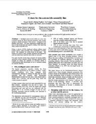
An active area <strong>of</strong> research is the treatment <strong>of</strong> retinal<br />
venous occlusion by delivery <strong>of</strong> anticoagulant drugs<br />
directly to blood clots in retinal vessels [1,2,41.<br />
Shortcomings <strong>of</strong> micro manipulators currently being used<br />
in such research have motivated the development <strong>of</strong> a new<br />
tool. In order to better explain the design constraints,<br />
some steps which are included in a typical procedure are<br />
outlined here. A hypodermic needle is inserted through<br />
the wall <strong>of</strong> the eye to gain access to the interior surface.<br />
A rigid glass micropipette is inserted through the<br />
hypodermic needle far enough that its tip protrudes<br />
beyond the end <strong>of</strong> the needle. The micropipette is guided<br />
to various injection sites on the retina by pivoting the<br />
hypodermic needle about its puncture point, that is, the<br />
point <strong>of</strong> intersection between the needle and the wall <strong>of</strong><br />
the eye. By keeping the needle nearly stationary at the<br />
point where it passes into the eye's interior, damage to the<br />
wall <strong>of</strong> the eye is minimized. A third allowable <strong>degree</strong> <strong>of</strong><br />
<strong>freedom</strong> is movement along the axis <strong>of</strong> the hypodermic<br />
needle since it does not de<strong>for</strong>m the wall <strong>of</strong> the eye at the<br />
puncture point significantly.<br />
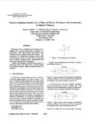
Most commercially available <strong>micromanipulator</strong>s are<br />
:igure 1: Schematic <strong>of</strong> a traditional sphericalmovement<br />
<strong>micromanipulator</strong>.<br />
1050-4729/93 $3.00 0 1993 IEEE<br />
630
Such <strong>micromanipulator</strong>s tend to be bulky because the<br />
mechanical tracks span the entire range <strong>of</strong> motion at all<br />
times, prohibiting the accommodation <strong>of</strong> multiple<br />
simultaneous entries into the eye. Another point <strong>of</strong><br />
functional inflexibility is that the center <strong>of</strong> spherical<br />
motion can not be moved with respect to the base <strong>of</strong> these<br />
manipulators due to the fixed radii <strong>of</strong> the mechanical<br />
tracks .<br />
As an alternative to these gimbal-type devices which<br />
are physically constrained to the desired "puncturecentered<br />
movement, the <strong>six</strong> DOF parallel device can be<br />
constrained mathematically by its computer controller.<br />
The advantage is not only the versatility gained by<br />
redundant <strong>degree</strong>s <strong>of</strong> <strong>freedom</strong>, but also that <strong>of</strong><br />
compactness. A desirable size and shape <strong>for</strong> the device is<br />
that <strong>of</strong> a human wrist and hand gripping a slender tool.<br />
This will allow multiple manipulators to be used<br />
simultaneously on a single eye when necessary.<br />
The initial operation mode will be open loop wherein<br />
the operator will watch the end effector (through the<br />
pupil with the aid <strong>of</strong> a microscope) and guide it using a<br />
multi-dimensional joystick input device connected to a<br />
computer controller. Subsequent modes <strong>of</strong> operation<br />
will include <strong>for</strong>ce-reflecting bilateral control<br />
arrangement (discussed later in this paper).<br />
2. Kinematic Design<br />
2.1. Initial Choice<br />
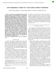
The Stewart Plat<strong>for</strong>m [lo] parallel <strong>six</strong> DOF robot<br />
scheme (figure 2) was chosen as a starting point <strong>for</strong> its<br />
inherent stiffness and compactness. (Merlet has<br />
Plat<strong>for</strong>m<br />
\<br />
Legs are Prismatic Joints<br />
Ul (Ball-Jointed at Each End)<br />
summarized several advantages not listed here [7].)<br />
Different geometries were evaluated through the<br />
definition <strong>of</strong> <strong>six</strong> quantities derived from the jacobian.<br />
Details follow.<br />
2.2. Coordinate Systems<br />
The traditional scheme <strong>of</strong> specifying end effector<br />
orientation with three euler angles will be slightly<br />
modified to better examine each manipulator design's<br />
suitability <strong>for</strong> the task at hand. Imagine a third<br />
coordinate system [U*V*W*] in addition to those<br />
pictured in figure 2 whose origin is always coincident<br />
with the [VVW] origin at the puncture point, and whose<br />
U*V* plane is always parallel to the XY plane. As the<br />
hypodermic end effector with rigidly attached system<br />
[UVW] is placed in some arbitrary orientation, the<br />
position <strong>of</strong> the tip <strong>of</strong> the needle can be projected onto the<br />
U*V* plane. (Recall that the puncture point is not, in<br />
general, at the tip <strong>of</strong> the needle.) The two coordinates<br />
(u*,v*) necessary to describe this projected tip position<br />
make up two <strong>of</strong> the three orientation variables. The third<br />
will be the angle <strong>of</strong> rotation y <strong>of</strong> the plat<strong>for</strong>m about the<br />
hypodermic. The position (x.y,z) <strong>of</strong> the puncture point in<br />
the [XYZ] frame completes the set <strong>of</strong> <strong>six</strong> variables needed<br />
to fully specify the position and orientation <strong>of</strong> the end<br />
effector.<br />
These choices were shaped by the microinjection task.<br />
During a procedure, the greatest part <strong>of</strong> the movement<br />
will be in the (u*,v*) coordinates, while rotation y about<br />
the needle has little effect and there<strong>for</strong>e is <strong>of</strong> little<br />
importance <strong>for</strong> this application.<br />
2.3. Sensitivity Parameters<br />
One important requirement in choosing a specific<br />
kinematic design was low sensitivity <strong>of</strong> endpoint position<br />
to perturbations in leg length, because amplification <strong>of</strong><br />
uncertainty in joint position is undesirable from the<br />
precision standpoint. Since the jacobian maps joint<br />
perturbations into endpoint perturbations, each Jacobian<br />
element can be thought <strong>of</strong> as a gain from joint to endpoint<br />
space.<br />
[ i] 6V*<br />
-<br />
cy<br />
'igure 2: Stewart plat<strong>for</strong>m schematic<br />
Endpoint<br />
Qlange<br />
Jacobian<br />
Joint<br />
-ge<br />
The sum <strong>of</strong> the absolute values <strong>of</strong> all Jacobian elements<br />
in a single row, (or the one-norm <strong>of</strong> each row vector) is<br />
some measure <strong>of</strong> a "worst-case" gain, mapping a<br />
631
simultaneous unit perturbation in all joints to a<br />
perturbation in one <strong>of</strong> the <strong>six</strong> endpoint coordinates. For<br />
the fnst row <strong>of</strong> the jacobian, define the sensitivity Sl to<br />
be<br />
s1 =kl&l<br />
i= 1<br />
The vector comprising all <strong>six</strong> such sensitivity measures<br />
will be called the sensitivity vector <strong>for</strong> convenience in<br />
this paper. Since the sensitivity vector is different <strong>for</strong><br />
each position and orientation <strong>of</strong> the end effector <strong>of</strong> a given<br />
design, a few key positions were chosen as representative<br />
and considered across all designs. It should also be noted<br />
that comparison <strong>of</strong> sensitivity vectors is not a purely<br />
quantitative task, since one geometry might yield high<br />
sensitivity in one <strong>degree</strong> <strong>of</strong> <strong>freedom</strong> and low in another<br />
while the converse might be true in a second geometry.<br />
Knowledge <strong>of</strong> the movements that would be most critical<br />
in the microinjection application shaped the judgments <strong>of</strong><br />
which sensitivity measures to weigh more heavily, (such<br />
as (u*,v*)), and which to, in some cases, ignore completely<br />
(such as y). Yet another important point to note is that,<br />
while the vectors can be compared to one another,<br />
elements within one vector can not be directly compared.<br />
This is because the elements <strong>of</strong> the sensitivity vector<br />
corresponding to the rotational <strong>degree</strong> <strong>of</strong> <strong>freedom</strong> has<br />
units <strong>of</strong> (radians/length) while the translational DOF<br />
units are (lengwength).<br />
2.4. Mathematical Design Search Method<br />
The approach, using the symbolic manipulation<br />
s<strong>of</strong>tware package, Mathematica, was to leave the Stewart<br />
Plat<strong>for</strong>m geometry parameters <strong>of</strong> interest and the set <strong>of</strong><br />
endpoint coordinates as variables, and then to solve the<br />
inverse kinematics problem <strong>of</strong> finding the joint positions<br />
(leg lengths) as a function <strong>of</strong> those variables. This is<br />
straight<strong>for</strong>ward <strong>for</strong> a parallel manipulator, because once<br />
the coordinates <strong>of</strong> all leg attachment points are known in<br />
a single coordinate frame, leg lengths are found by vector<br />
differences. The inverse jacobian is then obtained by<br />
symbolically differentiating with respect to the joint<br />
positions. From this state, endpoint position and<br />
geometry values can be supplied, and the inverse jacobian<br />
evaluated and inverted to give the jacobian.<br />
Following this procedure, many geometries and<br />
endpoint positions can be examined without having to<br />
invert or differentiate with numerical methods.<br />
Parameters to be chosen included the diameter, Db, <strong>of</strong> the<br />
smallest circle circumscribing the leg attachments to<br />
ground (base size), a similar circle diameter, Dp, <strong>for</strong> the<br />
upper end leg attachments (plat<strong>for</strong>m size), and a nominal<br />
value, H, <strong>for</strong> the distance between plat<strong>for</strong>m and base.<br />
Two general areas <strong>of</strong> investigation into geometry<br />
effects were the ratio H:Dp (slenderness), and the ratio<br />
Dp:Db (conicalness). Table 1 shows a few examples <strong>of</strong><br />
the effects <strong>of</strong> geometry on sensitivity vectors.<br />
Sensitivity <strong>of</strong><br />
X v z v* y<br />
2 2 2 5.94 5.21 1.07 0.71 0.77 3.01<br />
2 4 2 7.48 7.67 1.24 0.86 0.76 1.74<br />
4 2 2 3.42 3.81 1.28 0.86 0.80 1.61<br />
2 2 6 12.11 12.43 1.01 0.67 0.72 8.48<br />
I<br />
I<br />
Table 1: Effect <strong>of</strong> three geometry parameters<br />
on the sensitivity vector.<br />
The U* and v* values, which are <strong>of</strong> primary importance <strong>for</strong><br />
microinjection, are best when the manipulator is slender<br />
(row 4). The trade<strong>of</strong>f is a significant degradation in x and<br />
y (using the first row as a reference). If the plat<strong>for</strong>m is<br />
large compared to the base (row 2), a similar but less<br />
severe trade<strong>of</strong>f results. The third row shows a conical<br />
design in which the base is twice the diameter <strong>of</strong> the<br />
plat<strong>for</strong>m. The x and y sensitivities are better than in the<br />
case <strong>of</strong> the cylindrical design <strong>of</strong> row 1, and U* and v* are<br />
not significantly worse. This design was rejected,<br />
however, in favor <strong>of</strong> row 1 on the basis <strong>of</strong> range <strong>of</strong> motion<br />
(which always competes with low sensitivity).<br />
3. Physical Design<br />
3.1. Stewart Plat<strong>for</strong>m<br />
Approaches to the physical design <strong>of</strong> a Stewart Plat<strong>for</strong>m<br />
can be divided into two classes: (1) legs either pull or<br />
push against an antagonistic <strong>for</strong>ce (i.e. a spring pushes the<br />
plat<strong>for</strong>m away from the base at all times while <strong>six</strong><br />
variable length cables constrain it [51), or (2) each leg is a<br />
linear actuator which can be commanded to a desired<br />
length.<br />
In order to get a reasonable range <strong>of</strong> motion and good<br />
response characteristics using approach (1) above, a<br />
considerable amount <strong>of</strong> potential energy must be stored in<br />
the antagonistic system. Failure <strong>of</strong> a leg connection in<br />
such a system could have catastrophic results in<br />
<strong>ophthalmic</strong> surgery. With approach (2), the biggest<br />
problems are the actuator's overall length, length to<br />
stroke ratio, and diameter to length ratio. Most <strong>of</strong> these<br />
quantities are much larger than desired with<br />
commercially available linear actuators, leading to<br />
problems with leg collisions, high sensitivity values, and<br />
poor range <strong>of</strong> motion.<br />
3.2. Variations on Initial Design<br />
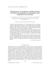
To circumvent some <strong>of</strong> these difficulties, a variation<br />
was devised (figure 3). This variation allows the linear<br />
actuators to remain fixed to ground rather than being ball<br />
jointed to ground, which in turn generates fewer<br />
prbblems with leg collisions and sensitivity parameter<br />
632
goals. This same variation was presented by Merlet [6]<br />
with the minor difference that Merlet's plat<strong>for</strong>m-end leg<br />
connections occur in three coincident pairs, while figure 3<br />
shows <strong>six</strong> distinct plat<strong>for</strong>m attachment points.<br />
It was also decided that the needle should not be<br />
mounted perpendicular to the plat<strong>for</strong>m in order to avoid<br />
collisions between the back end <strong>of</strong> the micropipette and<br />
the legs. (Recall that the micropipette is rigid and must<br />
pass all the way through the hypodermic needle.)<br />
Mounting at 45 <strong>degree</strong>s not only avoids collisions but<br />
makes micropipette access much more convenient yielding<br />
a more functional design.<br />
4. Future Work<br />
Following successful open loop operation, the<br />
<strong>micromanipulator</strong> will be fitted with end effector <strong>for</strong>ce<br />
sensing hardware and connected to a <strong>for</strong>ce reflecting<br />
macro manipulandum (already developed)[81. From this<br />
macro/mim bilateral manipulator plat<strong>for</strong>m, research in<br />
impedance shaping bilateral control can proceed. The goal<br />
<strong>of</strong> this research, the theory <strong>for</strong> which is described in detail<br />
in other papers [3], is to develop a computer mediated hand<br />
tool which reflects a "realistic feel" <strong>of</strong> the environment<br />
being encountered by the <strong>micromanipulator</strong> while<br />
per<strong>for</strong>ming a task on a level below that <strong>of</strong> human<br />
dexterity.<br />
5. Acknowledgments<br />
The authors gratefully acknowledge the support <strong>of</strong> The<br />
Margaret W. and Herbert Hoover Jr. Foundation in<br />
funding this project.<br />
i w<br />
%ure 3: Schematic <strong>of</strong> the Merlet Parallel<br />
Manipulator with 45 <strong>degree</strong> hypodermic needle<br />
end effector.<br />
These variations on the earlier manipulator design<br />
were not without cost. The sensitivity vector suffered<br />
somewhat. After considering the sensitivities, range <strong>of</strong><br />
motion and function, the final design now has leg length,<br />
plat<strong>for</strong>m diameter, and base diameter all <strong>of</strong> two inches<br />
yielding a sensitivity vector <strong>of</strong> (5.31,5.41, 1.50,0.48,0.89,<br />
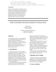
1.87). The physical design is also complete, and the<br />
manipulator is being fabricated (figure 4). It will be<br />
actuated by brush-type D.C. torque motors and ball<br />
screws.<br />
633
c)<br />
U<br />
c<br />
b<br />
El<br />
U<br />
Q<br />
3<br />
-<br />
n<br />
.-<br />
U<br />
.-<br />
E<br />
r<br />
0<br />
X<br />
cn<br />
Q<br />
0<br />
.-<br />
)I<br />
r<br />
0<br />
Q)<br />
U)<br />
P<br />
c)<br />
CI<br />
E<br />
.-<br />
I&<br />
U<br />
Q)<br />
3<br />
m<br />
L.<br />
G<br />
n<br />
E<br />
0<br />
I 2<br />
c,<br />
U<br />
Q<br />
c<br />
5<br />
cn<br />
U<br />
a,<br />
Q)<br />
E<br />
v<br />
Q<br />
9<br />
0<br />
c<br />
634
References<br />
[l] B. E. AUf. and E. De Juan Jr. In Vivo Cannulation <strong>of</strong><br />
Retinal Vessels. Graefe's Arch Clin Exp Ophthalmol.<br />
225221-225.1987.<br />
[2] B. Becker and L. P. Post. Retinal Vein Occlusion.<br />
American Journal <strong>of</strong> Ophthalmology, 34677-6861951.<br />
[3] J. E. <strong>Colgate</strong>. Power and Impedance Scaling in<br />
Bilateral Manipulation. Proc. 1991 IEEE Int'l Con$ on<br />
Robotics and Automation 3:2292-2297.<br />
[4] M. R. Glucksberg. and R. Dum. Direct Measurement<br />
<strong>of</strong> Retinal Microvascular Pressure in the Live<br />
Anesthetized Cat. Microvascular Research. in press,<br />
1992.<br />
[5] S. E. Landsberger and T. B. Sheridan. A Minimal,<br />
Minimal Linkage: The Tension-Compression Parallel<br />
Link Manipulator. Proceedings <strong>of</strong> the IMACS/SICE<br />
International. Symposium on Robotics, Mechatronics and<br />
Manufacturing System '92 Kobe, 1:493-500, 1992.<br />
[6] J-P. Merlet. Direct Kinematics and Assembly Modes<br />
<strong>of</strong> Parallel Manipulators. Int'l Journal <strong>of</strong> Robotics<br />
Research, 11 (2):150-162, 1992.<br />
[7] J-P. Merlet. Parallel Manipulators: State <strong>of</strong> the Art<br />
and Perspectives. Proceedings <strong>of</strong> the IMACYSICE<br />
International. Symposium on Robotics, Mechatronics and<br />
Manufacturing Systems '92 Kobe, 1:403-408, 1992.<br />
[8] P. A. Millman and J. E. <strong>Colgate</strong>. Design <strong>of</strong> a Four<br />
Degree-<strong>of</strong>-Freedom Force-Reflecting Manipulandum<br />
with a Specified ForcdTorque Workspace, Proc. I991<br />
IEEE Int'l Conf: on Robotics and Automation, 2 1488-<br />
1493.<br />
[9] C. J. Pournaras, R. D. Shonat, J-L. Munoz, and B.L.<br />
Petrig, New Ocular Micromanipulator <strong>for</strong><br />
Measurements <strong>of</strong> Retinal and Vitreous Physiologic<br />
Parameters in the Mammalian Eye. Experimental Eye<br />
Research, 53:723-727, 1991.<br />
[lo] D. Stewart. A Plat<strong>for</strong>m with 6 Degrees <strong>of</strong> Freedom.<br />
Proc. Inst. Mech. Engr., 180371-386, 1965.<br />
635