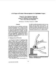
force sensors for human/robot interaction - Colgate - Northwestern ...
force sensors for human/robot interaction - Colgate - Northwestern ...
force sensors for human/robot interaction - Colgate - Northwestern ...

Create successful ePaper yourself
Turn your PDF publications into a flip-book with our unique Google optimized e-Paper software.
A<br />
V+<br />
Figure 3<br />
V+<br />
A<br />
A =<br />
<br />
<br />
<br />
r<br />
Dx<br />
¢<br />
3<br />
9<br />
2 - 0 0 0 -<br />
4<br />
4<br />
3 1<br />
3<br />
-<br />
0 0 0<br />
4 2<br />
4<br />
3 3 3 3<br />
0 0 p+ k p+ k - p 0<br />
8 4 8 4<br />
3 3 3 3<br />
0 0 p+ k p+<br />
k 0 0<br />
4 8 2 8<br />
3<br />
3 3<br />
0 0 - p 0 p+<br />
k 0<br />
4<br />
2 8<br />
9 3<br />
-<br />
0 0 0 3<br />
4 4<br />
<br />
<br />
Dx<br />
Dy<br />
Dz<br />
Dqx<br />
Dq<br />
y<br />
Dq<br />
z<br />
<br />
<br />
<br />
f<br />
f<br />
3<br />
L<br />
Et w A f<br />
=<br />
3<br />
t<br />
t<br />
t<br />
<br />
x<br />
y<br />
z<br />
x<br />
y<br />
z<br />
<br />
<br />
<br />
<br />
<br />
3<br />
L r<br />
¢<br />
Et w Af 3<br />
(1)<br />
(2)<br />
B<br />
V- V-<br />
Figure 4<br />
3.2 Compliance matrix<br />
V 0<br />
The shape of the flexure can be used to<br />
determine its compliance matrix. The flexure<br />
can be considered to be constructed of four<br />
identical L’s (See figure 2). The compliance<br />
matrix of these L’s is determined, assuming small<br />
deflections and simple stress distributions within<br />
the cross-section of the beam, as in [7]. The<br />
compliance matrix <strong>for</strong> one L is given below.<br />
B<br />
V<br />
where D r x is the displacement, L is the length of<br />
one side of the square sheet, E, t, and w are the<br />
modulus of elasticity, thickness, and width of the<br />
material, p=t 2 /h 2 is the aspect ratio squared,<br />
k<br />
E<br />
G<br />
= is the ratio of the modulus of elasticity<br />
and<br />
r<br />
the modulus of rigidity of the material, and<br />
f is the applied <strong><strong>for</strong>ce</strong>. These compliance<br />
matrices are translated and rotated so that they<br />
are positioned as in figure 2. Then the<br />
compliance matrix of the whole flexure<br />
assembly, C, is found by combining the<br />
compliances of the individual L’s<br />
C<br />
C<br />
=<br />
= A<br />
-1<br />
-<br />
i<br />
<br />
Í<br />
i <br />
1<br />
We find that<br />
<br />
<br />
(3)<br />
1<br />
20<br />
0 0 0 0 0<br />
0<br />
1<br />
20<br />
0 0 0 0<br />
0 0<br />
k + p<br />
p<br />
4( k + 4p)<br />
0 0 0<br />
0 0 0<br />
3( k + p)( k + 4p)<br />
p<br />
2<br />
12k + 80kp + 40p<br />
0 0<br />
2<br />
0 0 0 0<br />
3( k + p)( k + 4p)<br />
p<br />
2<br />
12k + 80kp + 40 p<br />
0<br />
2<br />
0 0 0 0 0<br />
3<br />
112<br />
(4)<br />
<br />
<br />
Dx<br />
r<br />
L r<br />
Et w Cf . (5)<br />
3<br />
= 3<br />
A number of insights can be gained from this<br />
compliance matrix. First, we notice that it is