force sensors for human/robot interaction - Colgate - Northwestern ...
force sensors for human/robot interaction - Colgate - Northwestern ...
force sensors for human/robot interaction - Colgate - Northwestern ...

You also want an ePaper? Increase the reach of your titles
YUMPU automatically turns print PDFs into web optimized ePapers that Google loves.
Contribution<br />
Existing commercial designs <strong>for</strong> multi-axis <strong><strong>for</strong>ce</strong><br />
<strong>sensors</strong> are very expensive, providing a disincentive<br />
to their routine and abundant use in <strong>human</strong>/<strong>robot</strong><br />
<strong>interaction</strong> as <strong><strong>for</strong>ce</strong> sensing handles. While <strong><strong>for</strong>ce</strong><br />
sensor design has not been a common topic in<br />
<strong>robot</strong>ics conferences <strong>for</strong> several years now, the<br />
beginnings of extensive work in <strong>human</strong>/<strong>robot</strong><br />
<strong>interaction</strong> make it a topic worth revisiting.<br />
Reviewers, please respect the confidentiality of the material described here until such time as a patent<br />
application has been filed. This will occur prior to any publication.<br />
FORCE SENSORS FOR HUMAN/ROBOT INTERACTION<br />
Andy Lorenz<br />
Michael A. Peshkin<br />
J. Edward <strong>Colgate</strong><br />
Department of Mechanical Engineering<br />
<strong>Northwestern</strong> University<br />
Evanston. IL 60208-3111<br />
Abstract<br />
Conventional <strong><strong>for</strong>ce</strong> <strong>sensors</strong> are overdesigned <strong>for</strong><br />
use in measuring <strong>human</strong> <strong><strong>for</strong>ce</strong> inputs, such as is<br />
needed in research and application of<br />
<strong>human</strong>/<strong>robot</strong> <strong>interaction</strong>. A new type of <strong><strong>for</strong>ce</strong><br />
sensor is introduced that is suited to <strong>human</strong>-<strong>robot</strong><br />
<strong>interaction</strong>. This sensor is based on<br />
optoelectronic measurements rather than strain<br />
gauges. Criteria <strong>for</strong> material selection and<br />
dimensioning are given.<br />
1. Introduction<br />
Human-<strong>robot</strong> <strong>interaction</strong> is an increasingly<br />
important field in <strong>robot</strong>ics. Often this <strong>interaction</strong><br />
is mediated by a <strong><strong>for</strong>ce</strong> sensor which is the<br />
primary control input <strong>for</strong> the <strong>human</strong>. Existing<br />
<strong><strong>for</strong>ce</strong> sensor designs are intended <strong>for</strong> use at the<br />
end effector of a <strong>robot</strong> to monitor assembly or<br />
machining <strong><strong>for</strong>ce</strong>s In these application very high<br />
stiffness may be needed. Commercial multi-axis<br />
<strong><strong>for</strong>ce</strong> <strong>sensors</strong> typically measure all six axes (three<br />
<strong><strong>for</strong>ce</strong>s and three torques).<br />
These requirements are unnecessarily stringent<br />
<strong>for</strong> <strong><strong>for</strong>ce</strong> <strong>sensors</strong> to be used in <strong>human</strong>-<strong>robot</strong><br />
<strong>interaction</strong>, and cause <strong><strong>for</strong>ce</strong> <strong>sensors</strong> to be so<br />
expensive as to restrict the development of<br />
<strong>human</strong>/<strong>robot</strong> applications. Since the <strong>human</strong> hand<br />
and arm are so compliant themselves, there is no<br />
need <strong>for</strong> the <strong><strong>for</strong>ce</strong> sensor itself to be orders of<br />
magnitude stiffer.<br />
The <strong><strong>for</strong>ce</strong> sensor described here is a two axis<br />
device designed to measure x-y <strong><strong>for</strong>ce</strong>s in the<br />
plane and to ignore the other four <strong><strong>for</strong>ce</strong>s and<br />
torques. It has far lower stiffness than<br />
commercial <strong>sensors</strong>, allowing approximately one<br />
millimeter of deflection at its full scale applied<br />
<strong><strong>for</strong>ce</strong> of 250N. It is simple and inexpensive,<br />
using optoelectronic devices in place of strain<br />
gauges.<br />
The <strong><strong>for</strong>ce</strong> sensor can be utilized in <strong>human</strong><strong>robot</strong><br />
coordination, ([3],[4]) teleoperation ([5]),<br />
and collaborative <strong>robot</strong>s ([1],[2]).<br />
2. Benefits of new design<br />
Human-<strong>robot</strong> <strong>interaction</strong> requires different<br />
properties of a <strong><strong>for</strong>ce</strong> sensor than typical <strong>robot</strong><br />
applications such as machining and assembly.<br />
These differences have substantial impact on<br />
how a <strong><strong>for</strong>ce</strong> sensor can be designed.<br />
2.1 Larger compliance
Humans are relatively insensitive to small<br />
displacements on the order of a millimeter. A<br />
<strong><strong>for</strong>ce</strong> sensor which allows a displacement of this<br />
order is not perceptually distinguishable from an<br />
ideally stiff one. Millimeter displacements would<br />
cause trouble if they occurred at the end effector<br />
of a <strong>robot</strong>, which can be thought of as needing<br />
(or benefiting from) the accuracy of a machine<br />
tool. So what advantages are obtained by<br />
loosening the restrictions on how much<br />
displacement is allowed?<br />
Presently, strain gauges are used in most<br />
commercially available <strong><strong>for</strong>ce</strong> <strong>sensors</strong>. Strain<br />
gauges measure the very slight bend of a flexure<br />
element caused by applied <strong><strong>for</strong>ce</strong>s. However,<br />
they are difficult to install and calibrate and are<br />
easy to break. While the strain gauge elements<br />
themselves are inexpensive, in practice their<br />
difficulty of application results in <strong>sensors</strong> costing<br />
thousands of dollars.<br />
In the design presented here, infrared<br />
LED/photodiode pairs are used as the key sensor<br />
element in place of strain gauges. Strain gauges<br />
can measure deflections on the order of microns,<br />
and so are applied to very stiff flexure elements.<br />
Photo<strong>sensors</strong> can be used to measure deflections<br />
on the order of millimeters, and thus are applied<br />
to much more compliant flexures. Photo<strong>sensors</strong><br />
suffer from some of the same problems as strain<br />
gauges, including nonlinearity and temperature<br />
sensitivity. However, these <strong>sensors</strong> have distinct<br />
advantages. Photo<strong>sensors</strong> are cheap, easy to<br />
mount, are a non-contact sensor, and are hard to<br />
break.<br />
In our design, due to properties of the<br />
photo<strong>sensors</strong> and the flexure, the axes are<br />
intrinsically decoupled; separate sensor elements<br />
are used to measure the x and y <strong><strong>for</strong>ce</strong><br />
components. Since the axes are decoupled, less<br />
electronics is needed, and calibration issues are<br />
much simpler.<br />
is the resistance of the <strong><strong>for</strong>ce</strong> sensor to large<br />
undesired <strong><strong>for</strong>ce</strong> components.<br />
For example, consider a person moving a<br />
payload suspended from an overhead rail system.<br />
Where does one put a <strong><strong>for</strong>ce</strong> sensor to read the<br />
<strong><strong>for</strong>ce</strong>s applied by the <strong>human</strong>? If one uses a<br />
handle, then the person must grab the device by<br />
the handle, even if it might easier <strong>for</strong> the person<br />
to grasp the payload directly. If one puts the<br />
<strong><strong>for</strong>ce</strong> sensor between the payload and the rail<br />
system, then manipulating the object directly is<br />
allowed, but the <strong><strong>for</strong>ce</strong> sensor must withstand the<br />
weight of the payload. The type of <strong><strong>for</strong>ce</strong> sensor<br />
presented here would be ideal <strong>for</strong> this problem,<br />
as it can withstand large <strong><strong>for</strong>ce</strong>s out of the plane to<br />
be measured.<br />
2.2 Fewer degrees of freedom<br />
In an instance where a <strong>human</strong> controls a <strong>robot</strong><br />
with fewer than six degrees of freedom, the <strong><strong>for</strong>ce</strong><br />
sensor need not have six degrees of freedom.<br />
Fewer degrees of freedom means a simpler<br />
mechanical design, less electronics and wires,<br />
fewer sensor elements, and less calibration.<br />
One benefit of the design, which follows<br />
partially from having fewer degrees of freedom,
3. Design<br />
3.1 Overview<br />
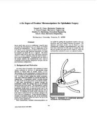
The <strong><strong>for</strong>ce</strong> sensor is shown in figure 1. The<br />
outer mount is the housing, while the handle is<br />
connected to the inner piece. Connecting the two<br />
pieces is a flexure element, best seen in the upper<br />
part of figure 2. The flexure alone is shown in<br />
the lower part of figure 2. As <strong><strong>for</strong>ce</strong>s are applied<br />
to the handle, the flexure allows a displacement<br />
to occur between the two pieces. Due to the 30:1<br />
(typical) aspect ratio of the flexure, it does not<br />
bend significantly in response to <strong><strong>for</strong>ce</strong>s in the z-<br />
direction or torques about the x and y axes.<br />
Figure 1<br />
Figure 2<br />
The flexure is designed to withstand one<br />
millimeter of motion between the inner and outer<br />
pieces, at which point the two pieces physically<br />
make contact preventing further motion. This<br />
protects the flexure from being broken.<br />
The displacement of the inner piece is<br />
measured using infrared “reflective object”<br />
sensor elements. These sensor elements are<br />
mounted on a printed circuit board which is<br />
attached to the inner piece. Each sensor element<br />
contains an infrared LED and a photodiode,<br />
pointing in the same direction. Light from the<br />
LED reflects off the inside wall of the outer piece<br />
and is detected by the photodiode, as shown in<br />
figure 3.<br />
For each <strong><strong>for</strong>ce</strong> axis, there are two sensor<br />
elements measuring the distance to the two walls<br />
of the outer object. The sensor elements labeled<br />
A and B in figure 3 <strong>for</strong> example, are <strong>for</strong><br />
measuring the x <strong><strong>for</strong>ce</strong>.<br />
Each pair of sensor elements is incorporated<br />
into a circuit shown in figure 4. The output<br />
voltage is approximately linearly related to the<br />
displacement, <strong>for</strong> small displacements. For the<br />
small deflections discussed here, the<br />
displacement is proportional to the <strong><strong>for</strong>ce</strong><br />
applied..
A<br />
V+<br />
Figure 3<br />
V+<br />
A<br />
A =<br />
<br />
<br />
<br />
r<br />
Dx<br />
¢<br />
3<br />
9<br />
2 - 0 0 0 -<br />
4<br />
4<br />
3 1<br />
3<br />
-<br />
0 0 0<br />
4 2<br />
4<br />
3 3 3 3<br />
0 0 p+ k p+ k - p 0<br />
8 4 8 4<br />
3 3 3 3<br />
0 0 p+ k p+<br />
k 0 0<br />
4 8 2 8<br />
3<br />
3 3<br />
0 0 - p 0 p+<br />
k 0<br />
4<br />
2 8<br />
9 3<br />
-<br />
0 0 0 3<br />
4 4<br />
<br />
<br />
Dx<br />
Dy<br />
Dz<br />
Dqx<br />
Dq<br />
y<br />
Dq<br />
z<br />
<br />
<br />
<br />
f<br />
f<br />
3<br />
L<br />
Et w A f<br />
=<br />
3<br />
t<br />
t<br />
t<br />
<br />
x<br />
y<br />
z<br />
x<br />
y<br />
z<br />
<br />
<br />
<br />
<br />
<br />
3<br />
L r<br />
¢<br />
Et w Af 3<br />
(1)<br />
(2)<br />
B<br />
V- V-<br />
Figure 4<br />
3.2 Compliance matrix<br />
V 0<br />
The shape of the flexure can be used to<br />
determine its compliance matrix. The flexure<br />
can be considered to be constructed of four<br />
identical L’s (See figure 2). The compliance<br />
matrix of these L’s is determined, assuming small<br />
deflections and simple stress distributions within<br />
the cross-section of the beam, as in [7]. The<br />
compliance matrix <strong>for</strong> one L is given below.<br />
B<br />
V<br />
where D r x is the displacement, L is the length of<br />
one side of the square sheet, E, t, and w are the<br />
modulus of elasticity, thickness, and width of the<br />
material, p=t 2 /h 2 is the aspect ratio squared,<br />
k<br />
E<br />
G<br />
= is the ratio of the modulus of elasticity<br />
and<br />
r<br />
the modulus of rigidity of the material, and<br />
f is the applied <strong><strong>for</strong>ce</strong>. These compliance<br />
matrices are translated and rotated so that they<br />
are positioned as in figure 2. Then the<br />
compliance matrix of the whole flexure<br />
assembly, C, is found by combining the<br />
compliances of the individual L’s<br />
C<br />
C<br />
=<br />
= A<br />
-1<br />
-<br />
i<br />
<br />
Í<br />
i <br />
1<br />
We find that<br />
<br />
<br />
(3)<br />
1<br />
20<br />
0 0 0 0 0<br />
0<br />
1<br />
20<br />
0 0 0 0<br />
0 0<br />
k + p<br />
p<br />
4( k + 4p)<br />
0 0 0<br />
0 0 0<br />
3( k + p)( k + 4p)<br />
p<br />
2<br />
12k + 80kp + 40p<br />
0 0<br />
2<br />
0 0 0 0<br />
3( k + p)( k + 4p)<br />
p<br />
2<br />
12k + 80kp + 40 p<br />
0<br />
2<br />
0 0 0 0 0<br />
3<br />
112<br />
(4)<br />
<br />
<br />
Dx<br />
r<br />
L r<br />
Et w Cf . (5)<br />
3<br />
= 3<br />
A number of insights can be gained from this<br />
compliance matrix. First, we notice that it is
diagonal, which tells us that <strong><strong>for</strong>ce</strong>s and torques<br />
create only their own corresponding motions. It<br />
also tells us how the choice of the aspect ratio<br />
(squared) p affects the design. If p is small, then<br />
the flexure moves significantly only in response<br />
to the <strong><strong>for</strong>ce</strong>s f x , f y , and τ z . This is how the<br />
present design is made. However, if p is large,<br />
then we have a flexure that responds to f z , τ x , and<br />
τ y . Also we see how the dimensions of the<br />
flexure, L, t and w, matter.<br />
3.3 Material selection<br />
The flexure must be able to deflect a desired<br />
displacement x d when the full scale <strong><strong>for</strong>ce</strong> F is<br />
applied in the x (or y) direction. m The flexure<br />
must not break of fatigue at this deflection. The<br />
deflection as a function of <strong><strong>for</strong>ce</strong> can be obtained<br />
from equation 5. It is<br />
3<br />
FL<br />
x ¢ D d<br />
x = 1<br />
20 Et w<br />
3<br />
(6)<br />
where F = f x<br />
from equation 1. From a simple<br />
materials [7] analysis, we find that the maximum<br />
moment M max , is related to the applied <strong><strong>for</strong>ce</strong> by<br />
M<br />
max<br />
= 3<br />
40<br />
FL<br />
The moment of inertia, I, of the flexure when<br />
bent about the z-axis is<br />
I<br />
= 1<br />
12<br />
wt<br />
3<br />
(7).<br />
(8)<br />
We want the maximum stress to be a factor of<br />
safety less than the yield stress. The equation <strong>for</strong><br />
the maximum stress is then<br />
s<br />
max<br />
M<br />
s<br />
maxc<br />
9 FL y<br />
= = <<br />
I 20 wt F. S.<br />
2<br />
(9)<br />
where c =t/2 is the maximum distance from the<br />
normal axis of the flexure, s y<br />
is the yield stress,<br />
and F.S. is the factor of safety desired. From<br />
equations (6) and (9), we can find equations<br />
restricting the length L and thickness t of the<br />
material.<br />
L<br />
< 9 3<br />
20<br />
( FS . .) xd<br />
F<br />
13 /<br />
w<br />
F<br />
t =<br />
xEw L 20<br />
d<br />
23 / 13 /<br />
E<br />
s<br />
23 /<br />
y<br />
(10)<br />
3 (11)<br />
We want to be able to make a sensor as small<br />
as is possible. This implies minimizing L. Thus<br />
we should choose a material that will minimize<br />
E 2/3 /s y<br />
, or will maximize<br />
32 /<br />
s y<br />
. (12)<br />
E<br />
Certain materials score well by this criteria<br />
([6]). One is high tensile strength steel, such as<br />
the “spring steel” we have used. Other high<br />
scores are nylon and certain rubbers. The<br />
rubbers are probably not feasible, as the<br />
thickness, t, would have to be so large as to make<br />
the design unreasonable, but nylon or other<br />
plastics may be a feasible material. Spring steel<br />
has good fatigue properties (when a F.S. of 2 or<br />
greater is used), and this may be a problem with<br />
plastics. However, spring steel is difficult to<br />
machine and bend, as its hardness is similar to<br />
that of machine tools and it is rather brittle<br />
outside its elastic range.<br />
For spring steel, F.S.=2, y d =1 mm, w=1.9 cm,<br />
F=66.3 lb., we find L min =4 cm=1.6 in. This is the<br />
value used in the prototype.<br />
3.4 Sensor considerations<br />
As mentioned above, infrared photo<strong>sensors</strong><br />
are used to detect displacement. The<br />
arrangement of the <strong>sensors</strong> in the design are<br />
shown in figure 3. One pair of <strong>sensors</strong> detects<br />
motions in the x direction, while the other pair of<br />
<strong>sensors</strong> detects motions in the y direction. The<br />
photo<strong>sensors</strong> are reflective, and shine on a<br />
uni<strong>for</strong>m reflective flat surface on the outer piece.<br />
The <strong>sensors</strong> detect when the wall comes closer or<br />
farther, and are immune to motions parallel with<br />
the wall.<br />
This causes the measurements of the two pairs<br />
of <strong>sensors</strong> to be independent, and to measure<br />
only their own axis. In addition to this, it causes<br />
the <strong>sensors</strong> to be relatively insensitive to small<br />
torques about the z axis. Thus only large z<br />
torques that cause range problems <strong>for</strong> the device
need to be worried about. (Due to the<br />
compliance matrix, other unwanted <strong><strong>for</strong>ce</strong><br />
components, f z , τ x , and τ y , do not have this<br />
concern.)<br />
It was found <strong>for</strong> the photosensor used, QT<br />
Optoelectronic’s OPB706A reflective sensor,<br />
that a decent trade-off between sensitivity and<br />
linearity of the sensor response could be obtained<br />
if the maximum displacement allowed by the<br />
flexure was ±1mm.<br />
4. Three-axis <strong><strong>for</strong>ce</strong> sensor design<br />
Another design <strong>for</strong> a similar <strong><strong>for</strong>ce</strong> sensor is<br />
shown in figure 5. In this design, there are three<br />
pairs of beams in series. An inner piece is<br />
attached at the 2 locations labeled B (One is<br />
hidden.). An outer piece is attached at the 4<br />
locations labeled A. The heavily shaded beams<br />
are thick and do not bend significantly. The<br />
beams labeled a, b, and g allow flexing in the x,<br />
y and z directions respectively. Each pair of<br />
beams allows only motion in one direction. All<br />
together this design allows motion only in x, y<br />
and z, and allows no twisting of the device. As<br />
be<strong>for</strong>e, photo<strong>sensors</strong> could be used to measure<br />
displacements. There would then be 3 pairs of<br />
<strong>sensors</strong> instead of two.<br />
This design is more complicated. In addition,<br />
it lacks some of the compactness of the first<br />
design, which can be relatively short in the z<br />
direction. However, this design is insensitive to<br />
all torques and can withstand large torques<br />
without breaking or affecting readings.<br />
Figure 5<br />
5. Measurements<br />
Linearity, noise, and DC offset drift<br />
measurements will be added as soon as<br />
completed.<br />
6. Summary<br />
A new <strong><strong>for</strong>ce</strong> sensor design was described in<br />
this paper. It is much cheaper and easier to<br />
construct than existing commercial <strong><strong>for</strong>ce</strong> <strong>sensors</strong>.<br />
The reduced degrees of freedom (two or three<br />
in contrast to six) allows a different class of<br />
flexures to be used, two of which are mentioned<br />
above. These flexures have a diagonal<br />
compliance matrix.<br />
The greater allowable compliance in<br />
<strong>human</strong>/<strong>robot</strong> applications makes new simpler and<br />
cheaper <strong><strong>for</strong>ce</strong> <strong>sensors</strong> possible. In addition it<br />
allows the use of new types of <strong>sensors</strong>.<br />
The <strong><strong>for</strong>ce</strong> sensor described above allows<br />
measurement of <strong><strong>for</strong>ce</strong>s in a plane. It is<br />
insensitive to other <strong><strong>for</strong>ce</strong> components. These<br />
<strong><strong>for</strong>ce</strong> components do not significantly bend the<br />
flexure, thus they do not have to be measured and<br />
then cancelled. The designs can be modified so<br />
that these <strong><strong>for</strong>ce</strong> components can be very large,<br />
and still not break or significantly bend the<br />
flexure.
The combination of this class of flexures and<br />
photo<strong>sensors</strong> allows the axes to be orthogonal,<br />
simplifying sensor placement, electrical design,<br />
and calibration.<br />
REFERENCES<br />
[1] J. E. <strong>Colgate</strong>, W. Wannasuphoprasit, and M. A.<br />
Peshkin, “Cobots: Robots <strong>for</strong> Collaboration with<br />
Human Operators,” Proc. 1996 ASME Int. ME Cong.<br />
and Exhib., Atlanta, GA, DSC-Vol. 58, pp. 433-39.<br />
[2] W. Wannasuphoprasit, R. B. Gillespie, J. E. <strong>Colgate</strong>,<br />
M. A. Peshkin, “Cobot Control,” Proc. 1997 IEEE Int.<br />
Conf. on R&A, Albuquerque, NM, pp. 3571-3577.<br />
[3] O. M. Al-Jarrah and Y. F. Zheng, “Arm-Manipulator<br />
Coordination <strong>for</strong> Load Sharing Using Compliant<br />
Control,” Proc 1996 Int. Conf on R&A, Columbus,<br />
OH, pp. 1000-1005.<br />
[4] K. I. Kim and Y. F. Zheng, “Human-<strong>robot</strong><br />
Coordination with Rotational Motion,” Proc. 1998<br />
IEEE Int. Conf. on R&A, Leuven, Belgium, pp. 3480-<br />
3485.<br />
[5] A.K. Bejczy and Z.F. Szakaly, “A harmonic motion<br />
generator(HMG) <strong>for</strong> tele<strong>robot</strong>ic applications,” Proc.<br />
1991 IEEE Int. Conf. on R&A, Sacramento, CA,<br />
1991, pp. 2032-2039.<br />
[6] M.F. Ashby, “Material Property Charts” ASM<br />
Handbook Vol. 20, pg. 266-280, ASM International,<br />
1997.<br />
[7] F. P. Beer and E. R. Johnston, Jr., Mechanics of<br />
Materials, McGraw-Hill, 1976