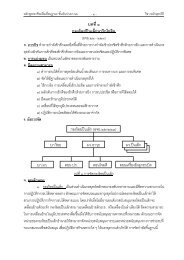
Inductance and Capacitance Measurements
Inductance and Capacitance Measurements
Inductance and Capacitance Measurements

You also want an ePaper? Increase the reach of your titles
YUMPU automatically turns print PDFs into web optimized ePapers that Google loves.
"ff<br />
<strong>Inductance</strong> <strong>and</strong> <strong>Capacitance</strong><br />
<strong>Measurements</strong><br />
Objectives<br />
You *ill be able to:<br />
l.<br />
)<br />
Sketch RC series <strong>and</strong> parallel equivalent circuits for a<br />
rela:ing the iwo circuits.<br />
capacitor, <strong>and</strong> write equations<br />
Sketch Rl series <strong>and</strong> parallel equivalent circuits for an inductor, <strong>and</strong> write equations<br />
relating the two .;ircuits.<br />
3. Explain the Q factor of an inductor <strong>and</strong> the D factor of a capacitor, <strong>and</strong> v.,rite the equations<br />
for each factor.<br />
4. Drau' circuit diagrams for the following ac bridges: simple capacitance bridge, seriesresistance<br />
capacitance bridge, parallel-resistanco capacitance bridge, inductance comparison<br />
bridge, Maxwell bridge, <strong>and</strong> Hay inductance bridge.<br />
5. Erplain the operation of each of the bridges listed above, derive the equations for the<br />
quantities to be measured, <strong>and</strong> discuss the advantages <strong>and</strong> disadvantages of each<br />
brid-ee.<br />
6. Sketch ac bridge circuit diagrams showing how a commercial rnultifunction impedance<br />
bridge uses a st<strong>and</strong>ard capacitor <strong>and</strong> three adjustable st<strong>and</strong>ard resistors to measure<br />
a wide range ofcapacitances <strong>and</strong> inductances. Explain.<br />
7. Discuss the problems involved in measuring small R, L, <strong>and</strong> C quantities, explain suitable<br />
measuring techniques, <strong>and</strong> calculate measured quantities.<br />
8. Sketch <strong>and</strong> explain the basic circuits for converting inductance <strong>and</strong> capacitance into<br />
voltages for digital measurements. Discuss the specification <strong>and</strong> performance of a digital<br />
RIC meter.<br />
9. Draw the circuit diagram for a Q meter, explain its operation <strong>and</strong> controls, <strong>and</strong> determine<br />
the Q of acoil from the Qmeter measurements.<br />
189
Introduction<br />
Inductancc, capacitai,ce, inductor Q factor, <strong>and</strong> capacitor D factor can all be measured<br />
precisely on ac bridges, which are adaptations of the Wheatstone bridge. An ac<br />
supply must be used, <strong>and</strong> the null detector musi be an ac instrument. A wide range<br />
of ac bridge circuits are available for various specialized measurements. Some commercial<br />
ac bridges use only a st<strong>and</strong>ard capacitor <strong>and</strong> three adjustable st<strong>and</strong>ard resistors<br />
to construct several different types of inductance <strong>and</strong> capacitance bridge circuits.<br />
Special techniques must be employed for measuring very small inductance <strong>and</strong> capacitance<br />
quantities. For digital measurement, inductance, capacitance, <strong>and</strong> resistance<br />
are first appiied to circuits that convert each quantity into a voltage. Capacitors <strong>and</strong><br />
inductors that are required to operate at high frequencies are best measured on a Q<br />
meter.<br />
3.1 RC AND RZ EQLIVALENT CIRCUITS<br />
Capacitor Equivalent Circuits<br />
Theequivalentcircuitofacapacitorconsistsofapurecapacitance Cp<strong>and</strong>aparallelresistance<br />
Rp. as iliustrated in Figure 8-1(a). Cp represents the actual capacitance value, <strong>and</strong><br />
ftp represents.the resistance of the dielectric or leakage resistancc. Capacitors that have a<br />
high leakage current flowing through the dielectric have a relatively low value of Rp in<br />
their equivalent circuit. Vc,y iow teakage currents are represented by extremely large values<br />
of Rp. Examples of the tv,'c extremes are electrolytic capacitors that have high leakage<br />
currents (low parallel resistance), <strong>and</strong> plastic film capacitors which have very low<br />
leakage (high parallel resistance). An electrolytic capacitor might easily have several microamperes<br />
of leakage crlrrent, while a capacitor with a plastic film dielectric could typically<br />
have a resistance as high as 100000 MO.<br />
A parallel RC circuit has an equivalent series RC circuit [Figure 8-1(b)]. Either one<br />
of the tu'o equivalent circuits (series or parallel) may be used to represent a capacitor in a<br />
circuit. It is found that capacitors with a high-resistance dielectric are best represented by<br />
the series RC circuit, while those with a low-resistance dielectric should be represented<br />
by the parallel equivalent circuit. However, when the capacitor is measured in terms of<br />
the series C <strong>and</strong> R quantities, it is usually desirable to resolve them into the parallel<br />
(u) Parallel equivalent<br />
circuit<br />
^, 1<br />
"l'T<br />
(b) Series equivalent<br />
circuit<br />
Figure 8-1 A capacitor may be represented<br />
by either a parallel equivalent circuit or a<br />
series equivalent circuit. The parallel equivalent<br />
circuit best represents capacitors that<br />
have a low-resistance dielectric, while the<br />
series equivalent circuit is most suitable for<br />
capacitors with a high-resistance dielectric.<br />
190 <strong>Inductance</strong> <strong>and</strong> <strong>Capacitance</strong> <strong>Measurements</strong> Chap. 8
*iln<br />
equivalent circuit quantities. This is because the (parallei) leakage resistance<br />
sents<br />
best<br />
the quality<br />
repre-<br />
of the capacitor dielectric. Equations ihat rela; the series<br />
equivalent<br />
<strong>and</strong> parallel<br />
circuits are derived belorv.<br />
Refening to Figure g_ l, the series impedance is<br />
<strong>and</strong> the parallel admittance is<br />
Thus,<br />
Zr= Rr- jX,<br />
y-=a*; I<br />
'n- 4*t4=Ge+iBe<br />
where G is conductance <strong>and</strong> ^B is susceptance. The impedances of each circuit must be<br />
equal.<br />
giving<br />
or<br />
glvmg<br />
Equating the real terms,<br />
(8-1)<br />
Equating the imaginary terms,<br />
a,= ^4 ^ ' R!+X!<br />
(8-2)<br />
The equations aborre.can be shown to apply also to equivarent series <strong>and</strong> parallel<br />
RZ circuits, as well as RCcircuits<br />
Sec. 8-l<br />
RC <strong>and</strong> RZ Equivalent Circuits<br />
tgt.
-<br />
.-ffi<br />
Inductor Equivalent Circuits<br />
Inductor equivalent circuits are illustrated in Figr"e 8-2. The :eries equivalent circuit in<br />
Figure 8-2(a) represents an inductor as 2 pur. inductance L" in series with the resistance<br />
oi its coil. Th;s series equivalent circuit is normally the best way to represent an inductor,<br />
because the actual winding resistance is involved <strong>and</strong> this is an important qua:rtity. Ideally,<br />
the winding resistance should be as small as possible, but this depends on the thickness<br />
<strong>and</strong> length of the wire used to wind the coil. Physically small high-value inductors<br />
tend to have large resistance values, while large low-inductance components are likely to<br />
have low resistances.<br />
The parallel RL equivalent circuit for an inductor [Figure 8-2(b)] can also be used.<br />
As in the case of the capacitor equivalent circuits, it is sometimes more convenient to use<br />
a parallel RL equivalent circuit rather than a series circuit. The equations relating the two<br />
are derived belorv.<br />
Referring to Figure 8-2, the series circuit irnpedance is<br />
<strong>and</strong> the parallel circuit admittance is<br />
R" +JX<br />
Z,= R,+ jX.,<br />
., I I<br />
f = - - t-<br />
-P<br />
RP " X,,<br />
Yr= Go-iB,<br />
Zr: Zp<br />
_1<br />
GP - jBp<br />
glvlng<br />
R.+x. =<br />
t (Go+iBr\<br />
Gp-iBp\Gr+ jBo )<br />
Gp+ jBp<br />
R, +iX, = Grr+ q<br />
9A<br />
I<br />
1I il t',<br />
I<br />
(a) Series equivalent<br />
circuit<br />
-1-<br />
(b) Parallel equivalent<br />
circuit<br />
Figure 8-2 An inductor may be represented<br />
by either a parallel equivalent circuit or a<br />
series equivalent circuit. The series equivalent<br />
circuit is normally used, but it is sometimes<br />
convenient to employ the parallel<br />
eouivalent circuit.<br />
192 <strong>Inductance</strong> <strong>and</strong> <strong>Capacitance</strong> <strong>Measurements</strong> Chap. 8
til<br />
*--<br />
Equrting the real terms,<br />
ft,=<br />
Gp<br />
G,l + r]<br />
1/RP I R;X; \<br />
rtR] + r/x] \ R:X: I<br />
RoxS<br />
xj +n]<br />
(8-3)<br />
Equating the imaginary terms,<br />
Y=<br />
Bp<br />
c| + n'z,<br />
llxp<br />
1/n] + ux]<br />
I R;X; \<br />
t"-"1<br />
\ R;X; )<br />
(8-4)<br />
Like Equations 8-1 <strong>and</strong> 8-2, Equations 8-3 <strong>and</strong> 8-4 applv to both RC <strong>and</strong> RL circuits'<br />
Q Factor of an Inductor<br />
The quality of an inductor can be defined in terms of its power dissipation. An ideal inductor<br />
should have zero winding resistance, <strong>and</strong> therefore zero power dissipated in the<br />
u,inding. A /oss,]' inductor has a relatively high winding resistance; consequently it does<br />
dissipate some power. The quatity factor, ot Qfactor; of the inductor is the ratio of the inductir-e<br />
reactance <strong>and</strong> resistance at the operating frequency.<br />
e=\='1"<br />
R, R"<br />
(8-5)<br />
where l, <strong>and</strong> R" refer to the components of an Rl series equivalent circuit [Figure 8-2(a)].<br />
Ideally. ol. should be very much larger than R", so that a very large Q factor is obtainede<br />
faciors for typical inductors range from a low ofless than 5 to as high as 1000 (depending<br />
on frequency).<br />
As discussed earlier, an inductor may be represented by either a series equivalent<br />
circuit or a parallel equivalent circuit. When the parallel equivalent circuit is employed,<br />
the Q factor can be shown to be<br />
Sec. 8-l RC <strong>and</strong> RL Equivalent Circuits 193
FE-*-<br />
.-ff|<br />
Q=&-<br />
Xp<br />
R'<br />
^Ln<br />
(8-0.1<br />
D Factor of a Capacitor<br />
The quality of a capacitor can be e;pressed in terms of its power dissipation. A very pure<br />
capacitance has a high dielectric resistance (low leakage current) <strong>and</strong> virtually zero power<br />
dissipation. A /ossy capacitor, which has a relatively low resistance (high leakage current),<br />
dissipates some power. The dissipationfactor D defines the quality of the capacitor.<br />
Like the Q factor of a coil, D is simply the ratio of the component reactance (at a given<br />
frequency) to the resistance measurable at its terminals. In the case of the capacitor, the<br />
resistance involved in the D-factor calculation is that showu in the parallel equivalent circuit.<br />
(This differs'from the inductor Q-factor calculation, where the resistance is that in<br />
the series equivalent circuit.) Using the pa rallel equivalent circuit:<br />
o=b<br />
Rp<br />
aCrR,,<br />
(8-7)<br />
Idealll', R, should be very much larger than l/(.iiCo), giving a very small dissipation<br />
factor. T1'picalll', D might range from 0.1 for electrolytic capacitors to less than 10< for<br />
capacitors u,ith a plastic film dielectric (again depending on frequency).<br />
\\rlren a series equivalent circuit is used, the equation for dissipatiorr factor can be<br />
shown to be<br />
D= R" =coCJ,<br />
x"<br />
(8-8)<br />
Comparing Equation 8-7 to 8-6.<strong>and</strong> Equation 8-8 to 8-5, it is seen that in each case<br />
D is the inverse of Q.<br />
Example 8-1<br />
An unknos'n circuit behaves as a 0.005 pF capacitor in series with a 8 kf,) resistor when<br />
measured at a frequency of I kHz. The terminal resistance is measured by an ohmmeter<br />
as 134 kQ. Determine the actual circuit components <strong>and</strong> the method of connection.<br />
Solution<br />
x"=<br />
I<br />
2nfC<br />
: 3l .8 kC)<br />
2r.xll
Equation 8-I<br />
Equatiott 8-2,<br />
o - R.r+ X.r _<br />
'.P-&-<br />
= 134 kO<br />
(8 k0)2 + (31.8 kO)'?<br />
8 kc)<br />
r = R: *^, = (8 kq)2 + (3r.8 k0)2<br />
31.8 ko<br />
^.<br />
= 33.8 kO<br />
c,,= 1<br />
' 2rJX,<br />
2rxlkHzx33.8kf)<br />
I<br />
_ 0.005 u.F<br />
Since the measured terminal resistance is 134 kO, the circuit must consist of a<br />
0.005 pF capacitor connected in parallel with a 134 kf) resistor. For a seriesconnected<br />
circuit, the terminal resistance would be rnuch higher than 134 k0.<br />
8-2 AC BzuDGE THEORY<br />
Circuit <strong>and</strong> Balance Equations<br />
The basic circuit of an ac bridge is illustrated in Figure 8-3. This is exactly the same as<br />
the Wtreatstone bridge circuit (Figure 7-3) except that impedances are shown instead of<br />
resistances. <strong>and</strong> an ac supply is used. The null detector must be an ac instrument such as<br />
an electronic galvanometer, headphones, or an oscilloscope.<br />
\\hen the null detector indicates zero in the circuit of Figure 8-3, the alternating<br />
volta-se across points a <strong>and</strong> b is zero. This means (as in the Wheatstone brirfge) that the<br />
voltage across Z, is exactly equal to that across 22, <strong>and</strong> the voltage across 23 equals the<br />
r,oltage drop across Za. Not only are the voltages equal in amplitude, they are also equal<br />
ac supply<br />
Figure 8-3 The basic ac bridge circuit is similar to the Wheatstone bridge except that<br />
impedances are involved instead ofresistances. An ac supply must be employed, <strong>and</strong> the<br />
null detector must be an ac instrument.<br />
Sec. 8-2 AC Bridge Theory 195
nI*-<br />
.-m<br />
in phase. If the voltages were equal in amplitude but not in<br />
would not indicate zero.<br />
Vzr = Vzz<br />
phase, the ac null detector<br />
i1Z. = i2Z2<br />
(l)<br />
-*<br />
<strong>and</strong><br />
or<br />
Vzt=Vzq<br />
iyZu= 1r7o<br />
(2)<br />
Dividing Equation I by Equation 2,<br />
irZr -<br />
itZt<br />
iz4<br />
izZ+<br />
giving<br />
(8-e)<br />
As already stated, bridge balance is obtained only when the voltages at each terminal<br />
of the rrull detector are equal in phase as well as in magnitude. This results in Equation<br />
8-9. u,hich involves complex quantities. In such an equation, the real parts of the<br />
quantities on each side must be equal, <strong>and</strong> the imaginary parts of the quantities must also<br />
be equal. Therefore, when deriving the balance equations for a particular bridge, it is best<br />
to express the impedances in rectangular form rather than polar form. The real quantities<br />
can then be equated to obtain one balance equation, <strong>and</strong> the imaginary (or7 quantities)<br />
can be equated to arrive at the other balance equation.<br />
The need for two balance equations arises from the fact that capacitances <strong>and</strong> inductances<br />
are never.pure; they must be defined as a combination of R <strong>and</strong> C or R <strong>and</strong> I<br />
(as discussed in Section 8-1). One balance equation permits calculation of L or C, <strong>and</strong> the<br />
other is used for determining the R quantity.<br />
Balance Procedure<br />
As already explained, two component adjustments are required to balance the bridge (or<br />
obtain a minimum indication on the null detector). These adjustments are ,?o/ independent<br />
of each other: one tends to affect the relative amplitudes of the voltages at each terminal<br />
^f the null detector, <strong>and</strong> the other adjustment has a marked effect on the relative phase<br />
difference of these voltages. For example, Za inFigure 8-3 might consist of a variable capacitor<br />
in series with a variable resistor, as illustrated in Figure 8-4(a). Adjustment of Ca<br />
ma1' make V7a equal in amplitude to V4 without bringing it into phase with V7j. The result<br />
is, of course, that the null detector voltage Vzt - Vz+ is not zero [see Figure 8-4(b)].<br />
Further adjustment of Co could alter the phase of VTabut will also alter its amplitude. If<br />
Ra is now adjusted, Vn - Vzo might be further reduced by bringing the voltages closer together<br />
in phase. However, this cannot be achieved without altering the amplitude of V2a,<br />
which is the voltage drop across Ra <strong>and</strong> Ca [Figure 8-4(c)]. When the best null has been<br />
obtained by adjustment of Ra, Ca is once again adjusted. This is likely to once more make<br />
L96 <strong>Inductance</strong> <strong>and</strong> <strong>Capacitance</strong> <strong>Measurements</strong> Chap. 8
qI<br />
/rt _ r/ \<br />
\v z3<br />
v z4l<br />
(a) Null detector voltage = (Vzz = Vzz)<br />
Yz+<br />
vzt<br />
vzA<br />
r: - t/<br />
t/<br />
rz3<br />
-rl<br />
vz4<br />
vzs - vzt<br />
(b) I'zs <strong>and</strong> V.4<br />
equal but not<br />
in-phase<br />
(rl<br />
Vzg <strong>and</strong> V74<br />
in-phase but<br />
not equal in<br />
amplitude<br />
(d)<br />
Vzs <strong>and</strong>, Vyn<br />
equal <strong>and</strong><br />
in-phase<br />
Figure 8-4 When an ac bridge is balanced, yzr must equal V^, <strong>and</strong> the two voltages<br />
must he in phase. This requires altemately adjusting two quantities (Ra <strong>and</strong> Ca in this circ))it)<br />
unt'l the smallest possible null detector indication is achieved.<br />
l/7. close toV..,in amplitude, but again has an unavoidable effect on the phase relationship.<br />
The procedure of alternately adjusting Ra <strong>and</strong> C4 to minimize the null detector voltage<br />
is continued until the smallest possible indication is obtained. Then, Vya is equal to<br />
VTborh in magnitude <strong>and</strong> phase [Figure 8-4(d)r.<br />
AC Bridge Sensitivity<br />
The same considerations that determined the sensitivity of a Wheatstone bridge apply t
iR<br />
in the measured quantity that causes the galvanometer to deflect from zero. Bridge sensitivity<br />
can be improved by using a more sensitive null detecior <strong>and</strong>/or by increasir-rg the<br />
level of supply voltage. The bridge sensitivity is analyzed by exactly the same method<br />
used for the Wheatstone bridge, except that impedances are involved instead of resistances.<br />
Accuracy of measurements is also determined in the sa;tle way as Wheatstone<br />
bridge accuracy.<br />
8-3 CAPACITANCE BRIDGES<br />
Simple <strong>Capacitance</strong> Bridge<br />
i-<br />
it<br />
The circuit of a simple capacitance bridge is illustrated in Figure 8-5(a). 21 is a st<strong>and</strong>ard<br />
capacitor C1, <strong>and</strong> Q is the unknown capacitance C,. 23 <strong>and</strong> Za arc known variable resistors.<br />
such as decade resistance boxes. When the bridge is balanced, 21/23 = 7alZa (Equation<br />
8-9) applies:<br />
z, = :11<br />
-<br />
z":<br />
toCr<br />
-<br />
-il<br />
aC*<br />
Zz: Rz <strong>and</strong> Z+= Ra<br />
(a) Simple capacitance bridge<br />
(b) Potential divider<br />
substituted for R, <strong>and</strong> Ra<br />
Figure 8-5 The simple capacitance bridge<br />
measures the unknown capacitance C, in<br />
terms of st<strong>and</strong>ard capacitor C1 <strong>and</strong> adjustable<br />
precision resistors R3 <strong>and</strong> Ra. At balance,<br />
c,= cl3lR4. This circuit functions<br />
only with capacitors that have very high resistance<br />
dielectrics.<br />
198 <strong>Inductance</strong> <strong>and</strong> <strong>Capacitance</strong> <strong>Measurements</strong> Chap- 8
fr<br />
Therefore,<br />
-jllaCt<br />
n3<br />
_<br />
iJ!'cu<br />
R4<br />
or<br />
l=<br />
CrRz<br />
I<br />
C'Rq<br />
glvrng<br />
(8-r0)<br />
The actual resistances of R3 <strong>and</strong> Ra zue not important if their ratio is knowno so a<br />
potential-divider resistance box could be used as shown in Figure 8-5(b).<br />
Example 8-2<br />
The st<strong>and</strong>ard capacitance value in Figure 8-5 is Cy = 0.1 pF, <strong>and</strong> R3lRa can be set to any<br />
ratio bet\\'een 100:1 <strong>and</strong> 1:100. Calculate the range of measurements of unknown capacitance<br />
Q'.<br />
Solution<br />
Fnrration R- l O<br />
For R3/Ra = 100: I :<br />
^<br />
r =-<br />
CBt<br />
R4<br />
C. = 0.1 F.F x 100<br />
I<br />
= l0 p.F<br />
ForR3/Ra=l:100:<br />
C,=0.1 pFr #<br />
= 0.001 p.F<br />
The foregoing analysis of the simple capacitance bridge assumes that the capacitors<br />
are absolutely pure, with effectively zero leakage current through the dielectric. If a resistance<br />
q,ere connected in series or in parallel with C. in Figure 8-5(a), <strong>and</strong> the rest ofthe<br />
bridge components remain as shown, balance would be virtually impossible to achieve.<br />
This is because i1 <strong>and</strong> i2 could not be brought into phase, <strong>and</strong> consequently, i1R3 <strong>and</strong> i2R4<br />
would not be in phase. As discussed in Section 8- 1, the equivalent circuit of a leaky capacitor<br />
is a pure capacitance in parallel with a pure resistance. Thus, the simple capacitance<br />
bridge is suitable only for measurernent of capacitors with high-resistance dielectrics.<br />
Sec. 8-3 <strong>Capacitance</strong> Bridges r99
Series-Resistance <strong>Capacitance</strong> Bridge<br />
In the circuit shown in iigu;'e 3-6(a), the unkr:..'w:r caDacirrnce is r';prcsented as a pure<br />
capacitance C5 in seri"s with a resirrance 1.,. A st<strong>and</strong>ard adjustable resistance R1 is connected<br />
in series with st<strong>and</strong>ard capacitor C1. The voltage drop across R, balances the resisrrvc<br />
voltage ilrops in branch 22when the bridge is balanced. The additional resistor in series<br />
u,ith C increases the total resistive component in 2., so that inconveniently small<br />
values of l(1 are not required to achieve balance. Bridge balance is most easily achieved<br />
when each capacitive branch has a substantial resistive component. To obtain balance, R1<br />
<strong>and</strong> either Rj or Ra are adjusted alternately. The .series-resistartce c'apacitance bridge is<br />
found to be most suitable for capacitors with a high-resistance dielectric (very low leakage<br />
currenl <strong>and</strong> low dissipation factor). When the bridge is balanced, Equation 8-9 apolies.<br />
Zt -Zt<br />
z1 z3<br />
giving<br />
Rr-jl/aCr _ R,-jllaC,<br />
R3 R.<br />
(8-rl)<br />
Equating the real terms in Equation 8-11,<br />
R,=R,<br />
R3 R"<br />
glvln-s (8- r 2)<br />
Equating the ima-einary terms in Equation 8- 11,<br />
1_1<br />
roClR-1 oC,R+<br />
giving (8-13)<br />
The phasor diagram for the series-resistance capacitance bridge at balance is drawn<br />
in Figure 8-6(bl. The voltage drops across 23 <strong>and</strong> Z" are i1R3 <strong>and</strong> i2Ro, respectively. These<br />
two volta_ees must be equal <strong>and</strong> in phase for the bridge to be balanced. Thus, they are<br />
drawn equal <strong>and</strong> in phase in the phasor diagram. Since R3 <strong>and</strong> Ra are resistive, i1 is in<br />
phase with ilRj <strong>and</strong> f2 is in phase with i2Ra. The impedance of C1 is purely capacitive,<br />
<strong>and</strong> current leads voltage by 90" in a pure capacitance. Therefore, the capacitor voltage<br />
200 <strong>Inductance</strong> <strong>and</strong> <strong>Capacitance</strong> <strong>Measurements</strong> Chap. 8
- r*f<br />
(a) Circuit of series-resistance capacitance bridge<br />
irRs = i2Rn<br />
.(b) Phasor diagram for balanced bridge<br />
Figure 8-6 The series-resistance capacitance bridge is similar to the simple capacitance<br />
bridge. except that an adjustable series resistance (R1) is included to balance the resistive<br />
component (R,) of 2". This bridge is most suitable for measuring capacitors with a highresis!ance<br />
dielectric.<br />
drop i1X6r is drawn 90" lagging ir. Similarly, the voltage drop across c" is i2X6.5, <strong>and</strong> is<br />
dran'n 90" lagging i2.The resistive voltage drops l,R1 <strong>and</strong> i2Rs are in phase with ir <strong>and</strong> i2,<br />
respectively.<br />
The total voltage drop across 21 is the phasor sum of i1R1 <strong>and</strong> i1X6.1, as illushated<br />
in Figure 8-6(b). Also, i2Z2 is the phasor sum of l2R" <strong>and</strong> i2Xs,. since i2z2<br />
must be equal to <strong>and</strong> in phase with iiT, ifrt <strong>and</strong> i2R" are equal, as are i1X6 <strong>and</strong>.<br />
izXcr.<br />
Sec. 8-3<br />
<strong>Capacitance</strong> Bridges 201
Example 8-3<br />
".g<br />
.i*er***<br />
'.aaaF<br />
=.aF*<br />
--##<br />
-.#ipr..l|<br />
,- aaa.#itaae<br />
.--ffi<br />
-#<br />
-....g<br />
-*'#<br />
..-w<br />
A series-resistance capacitance bndge [as in Figure 8-6(a)] has a 0.4 p,F st<strong>and</strong>ard capacitor<br />
for C1, <strong>and</strong> R: = 10 k(r. Baiance is achieved with a l0OHz supply frequency when<br />
Rr = 125 O <strong>and</strong> Ra = 14.7 kf,). Calculate the resistive <strong>and</strong> capacitive components of the<br />
measured capacitur <strong>and</strong> its dissipation factor.<br />
Solution<br />
EquationS-13, C,= +<br />
Equarion 8-12,<br />
= 0.068 p.F<br />
o - R,Ro<br />
-R3<br />
0.1 pF x 10 kO<br />
t4.7 k{l<br />
125 Ax M.7 kA<br />
l0 ko<br />
= 183.8 f)<br />
Equation 8-8,<br />
D = oC,R,<br />
= 2n x 100 Hz x 0.068 pF x 183.8 C)<br />
:0.008<br />
Parallel-Resistance <strong>Capacitance</strong> Bridge<br />
The circuit of a parallel-resistance capacitance bridge is illustrated in Figure 8-7. In this<br />
case, the unknown capacitance is represented by its parallel equivalent circuit; Crinparallel<br />
u'ith Ro. Z3 <strong>and</strong> Za are resistors, as before, either or both.of which may be adjustable.<br />
Q is balanced by a st<strong>and</strong>ard capacitor C1 in parallel with an adjustable resistor R1. Bridge<br />
balance is achieved by adjustment or R1 <strong>and</strong> either R3 or Ra. The parallel-resistance capacitance<br />
bridge is found to be most suitable for capacitors with a low resistance dielectric<br />
(relativell'high leakage current <strong>and</strong> high dissipation factor). At balance, Equation 8-9<br />
once again applies:<br />
Z, -Zt<br />
Z. Z^<br />
Also,<br />
1l<br />
-=-<br />
Zt<br />
Rr<br />
_1<br />
j(I/aC)<br />
I<br />
=-<br />
Rr<br />
+ jaCl<br />
1<br />
Ll= -<br />
llRt+ jaCt<br />
202<br />
<strong>Inductance</strong> <strong>and</strong> <strong>Capacitance</strong> <strong>Measurements</strong> Chap. 8
wsil'<br />
" dn*eho- 'rjffi<br />
Figure 8-7 The parallel-resistance capacitance bridge uses an adjustable resistance (Rr)<br />
connected in parallel with C1 to balance the resistive component (R) of Zz. This bridge is<br />
most suitable for measuring capacitors with a low-resistance dielectric.<br />
<strong>and</strong><br />
1=l* I<br />
4 Re jQlaCr)<br />
T^<br />
= - *JaLp<br />
Rp<br />
or<br />
.:<br />
substltuttng into Equation 8-9,<br />
4=l<br />
l/Ro+ jaC,<br />
I/(l/&+ jloCr) _ ll(llR,+ jaCo)<br />
R3<br />
1<br />
Rn<br />
1<br />
R3(l/Rr +j
giving (8-1 5)<br />
Equating the imaginary terms in Equation 8-14,<br />
yEf.-'Et<br />
rymt<br />
*ffi<br />
..,*'"-*i'llf'P<br />
' 'ry<br />
Solution<br />
1<br />
x"=<br />
2nfC" 2n x 100 Hz x 0.068 pF<br />
=23.4kQ<br />
Equation 8-1,<br />
^<br />
"n=<br />
nl+ x?<br />
&<br />
=<br />
(r83.8 fi)'? + e3.4kQ12<br />
l83so<br />
= 2.98 MO<br />
EquationS-2, x,= R?!x? -<br />
,4.r<br />
= 23.4 k{l<br />
(183.80)2 + (23.4kQ)2<br />
23.4kQ<br />
Co=<br />
'<br />
|<br />
2rJX,<br />
I<br />
2rr x 100 Hzx23.4kdl<br />
:0.068 p.F<br />
Front Equation 8-16,<br />
o _ CtRt _ 0.1 pFx l0kf)<br />
rr4- -<br />
Ce 0.068 p.F<br />
= 14.7 kQ<br />
From Equation 8-15,<br />
, -<br />
RtR,<br />
R4<br />
= 2.03 MO<br />
10 k.0 x 2.98MO<br />
4.7 kA<br />
The capacitor, which was determined in Example 8-3 as having a series equivalent<br />
circuit of 0.068 pF <strong>and</strong> 183.8 O, was shown in Example 8-5 to have a parallel equivalent<br />
circuit of 0.068 pF <strong>and</strong>298 MO. It was also shown that to measure the capacitor on a<br />
parallel-resistance capacitance bridge, R1 (in Figure 8-7) would have to be 2.03 MO. This<br />
is an inconveniently large value for a precision adjustable resistor. So a capacitor with a<br />
high leaka-ee resistance (low D factor) is best measured in terms of its series RC equivalent<br />
circuit.<br />
The capacitor in Example 8-4 has a parallel RC equivalent circuit of 0.068 pF<br />
<strong>and</strong> 551.3 kO. Conversion to the series equivalent circuit would demonstrate that this<br />
capacitor is not conveniently measured as a series RC circuit. Thus, a capacitor with a<br />
low leakage resistance (high D factor) is best measured as a parallel RC equivalent<br />
circuit.<br />
Capacitors with a very high leakage resistance should be neasured as series RC circuits.<br />
Capacitors with a low leakage resistance should be measured as parallel RC cir-<br />
Sec. 8-3 <strong>Capacitance</strong> Bridges 205
:riTiffi.<br />
:_*f*l*iiir<br />
I di-{*.ftiffidifrdt|L. ,ff<br />
cuits. Capacitors that have neither a very high nor a very low leakage resistance<br />
rr,casurec<br />
are best<br />
as a paraller RC circuit, because this gives u ii...t indicatioit of the<br />
leakage<br />
capacitor<br />
resistance.<br />
8.4 INDUCTANCE BRIDGES<br />
<strong>Inductance</strong> Comparison Bridge<br />
*!@r...t<br />
.*klM<br />
The circuit of the inductance comparison bridge shown in Figure g_g<br />
series-resistance<br />
is similar to the<br />
capacitance bridge except that inductors are in*volved instead<br />
tors' The<br />
of<br />
unknown<br />
capaci-<br />
inductance' represented by its (series equivalent circuit)<br />
<strong>and</strong><br />
inductance<br />
R'' is measured<br />
z,<br />
in terms of a precise staniard value inductor. zr is the<br />
tor'<br />
st<strong>and</strong>ard<br />
R' is a<br />
induc-<br />
variable st<strong>and</strong>ard resistor to balance R,, R3 <strong>and</strong> Ra are st<strong>and</strong>ard<br />
ance<br />
resistors.<br />
of the bridge<br />
Bal-<br />
is achieved by alternatery adjusting R1 <strong>and</strong> either R3<br />
Equation<br />
or Ra. At barance,<br />
8-9 once again applies:<br />
tt<br />
=tt<br />
Z, 24<br />
R, + jaLl R,+ iaL"<br />
R3<br />
R4<br />
Rt .aL, * = _& a;.L,<br />
Rj<br />
-Rr<br />
R4'Ro<br />
(8-17)<br />
Equating the real components in Equation g_17.<br />
Rr=<br />
R3<br />
R"<br />
R^<br />
Figure 8-8 The inductance comparison<br />
bridge uses a st<strong>and</strong>ard inductor Z, together<br />
with adjustable precision resistors R1, R3<br />
<strong>and</strong> Ro to measure an unknown inductor<br />
in terms of its series equivalent circuit Z-<br />
<strong>and</strong> R-.<br />
2M<br />
lnductance <strong>and</strong> <strong>Capacitance</strong> <strong>Measurements</strong><br />
Chap. g
ij*..fl<br />
glvlng (8-13)<br />
Equating th" imaginary components in Equation 8-17,<br />
aLr<br />
R3<br />
_ aL"<br />
R4<br />
gvlrrg<br />
(8-1e)<br />
"r-*"<br />
t"<br />
An inductor that is marked as 500 mH is to be measured on an inductance comparison<br />
brid-ee. The bridge uses a 100 mH st<strong>and</strong>ard inductor for L1, <strong>and</strong> a 5 kO st<strong>and</strong>ard resistor<br />
for R.. If the coil resistance of the 500 mH inductor is measured as 270 f,). determine the<br />
resistances of R1 <strong>and</strong> R3 (in Figure 8-8) at which balance is likely to occur.<br />
Solution<br />
From Equation 8-19, o -RoLr -<br />
r\3 - - -<br />
L,<br />
=1kC)<br />
5kOx100mH<br />
500 mH<br />
Frotn Equation 8-18, ^ R"R" 270.f, x I kO<br />
R4 5ko<br />
=54f)<br />
Nlaxnell Bridge<br />
Accurate pure st<strong>and</strong>ard capacitors are more easily constructed than st<strong>and</strong>ard inductors.<br />
Consequently, it is desirable to be able to measure inductance in a bridge that uses a capacitance<br />
st<strong>and</strong>ard rather than an inductance st<strong>and</strong>ard. "[he Manuell bridge (also known<br />
as the Maneell-Wein bridge) is shown in Figure 8-9. In this circuit, the st<strong>and</strong>ard capacitor<br />
C3 is connected in parallel with adjustable resistor R3. R1 is again an adjustable st<strong>and</strong>ard<br />
resistor. <strong>and</strong> Ra may also be made adjustable. l,, <strong>and</strong> R, represent the inductor to be<br />
measured.<br />
The Maxwell bridge is found to be most suitable for measuring coils with a low Q<br />
factor (i.e., where
Figure 8-9 The N{axrvell bridge uses a st<strong>and</strong>ard capacitor C3 <strong>and</strong> three adjustable preclsion<br />
resistors to measure an unknown inductor in terms of its series equivalent circuit, Z,<br />
<strong>and</strong> R,. This bridge is most suitable for measuring coils with a low Q factor.<br />
<strong>and</strong><br />
1=1_ 1<br />
=l<br />
23 R3 jllaQ R3<br />
I<br />
7.- '<br />
llfu+ jaC3<br />
Zz= R,+ joL"<br />
Substituting for all components in Equation 8-9,<br />
Rr<br />
tt(r/&+ jaQ)<br />
+ jaC3<br />
R" +"1'rol,<br />
R4<br />
&*rrC.R,=&<br />
*j^L,<br />
R3 R4 R4<br />
(8-20)<br />
Equating the real components in Equation 8-20,<br />
::::"-. Rr -<br />
R"<br />
DD<br />
r\?<br />
t\a<br />
or<br />
[-4&l<br />
| *'l<br />
Equating the imaginary components in Equation 8-20,<br />
(8-21)<br />
208 <strong>Inductance</strong> <strong>and</strong> <strong>Capacitance</strong> <strong>Measurements</strong> Chap. 8
qffi<br />
..i-*ii#f*k-'*;sa$*r.rr.flfliiia.-I.i.iiiii!ktrii*ri*ri*'r'**idfl**ir*r*liaii-|.**r lifu '{l}rl<br />
uC3R, = tL'<br />
R4<br />
glvrng (8-22)<br />
Example 8-7<br />
A Maxq,ell inductance bridge uses a st<strong>and</strong>ard capacitor of Cj = 0. I p,F <strong>and</strong> operates at a supplyfrequencyof<br />
l00Hz.BalanceisachievedwhenRl =1.26kA,R2=410,f),<strong>and</strong>Ro=JQ6<br />
f|. Calculate the inductance <strong>and</strong> resistance of the measured inductor, <strong>and</strong> determine its Q<br />
factor.<br />
Solutiott<br />
Equatiort 8-22, L, = CzRtR+<br />
= 0.1 pF x 1.26 kO x 500 O<br />
=63mH<br />
Equariott8'21, R,= +& = -Eqlaf4q-q<br />
-<br />
R. 470Q<br />
= 1.34 kCl<br />
Equation 8-5,<br />
Q = tL' - 2t x 1oo Hz T 63 mH<br />
R, 1.34 kc).<br />
0.03<br />
Ha1-<strong>Inductance</strong> Bridge<br />
The fla-r' bridge circuit in Figure 8-10 is similar to the Maxwell bridge, except that R3 <strong>and</strong><br />
C-r ?r€ cont€cted in series instead of parallel, <strong>and</strong> the unknown inductance is represented<br />
as a parallel l,R circuit instead of a series circuit. The balance equations are found to be<br />
exactl]' the same as those for the Maxwell bridge. It must be remembered, however, that<br />
the measured L, <strong>and</strong> R, are a parallel equivalent circuit. The equivalent series RI, circuit<br />
can be determined by substitution into Equations 8-3 <strong>and</strong> 8-4.<br />
\Vtren the bridge in Figure 8-10 is balanced,<br />
Z, =4<br />
Z^ Z^<br />
glvlng<br />
Ra .Ro Ra I<br />
t-<br />
(8-23)<br />
-<br />
Rp aLp<br />
- .<br />
Rr olC:Rr<br />
Sec. 8-4 <strong>Inductance</strong> Bridses 209
!6itl"trtffii:L<br />
;*il<br />
Figure 8-10 The Hay bridge uses a st<strong>and</strong>ard capacitor C3 <strong>and</strong> three adjustable precision<br />
resistors to measure an unknown inductor in terms of its parallel equivalent circuit, Lo<br />
<strong>and</strong> Rr. This circuit is most suitable for inductors with a high Q factor.<br />
Equating the real components in Equation 8-23,<br />
&=&<br />
RP Ri<br />
(8-24)<br />
Equatin-e the imaginary components in Equation 8-23,<br />
R^l<br />
aLp - oC3R1<br />
giving<br />
(8-2s)<br />
"n-t.<br />
*<br />
A Hay bridge operating at a supply frequency of 100 Hz is balanced when the components<br />
are Cr = 0.1 FF, Rr = I.26 kO, R3 = 75 O, <strong>and</strong> R4 = 500 f,). Calculate the inductance<br />
<strong>and</strong> resistance of the measured inductor. Also, determine the Q factor of the<br />
coil.<br />
zto <strong>Inductance</strong> <strong>and</strong> <strong>Capacitance</strong> <strong>Measurements</strong> Chap. 8
Yfi<br />
st*Et@uattf:E*tf.*iflir;ffi<br />
.-lI<br />
Solution<br />
Equation 8-25, Lp= C3Rfia<br />
= 0.1 p.F x 1.26 kO x 500 O<br />
=63mH<br />
Equations-24, R"= - 1'26 k!l!5oo o<br />
#<br />
= 8.4 kC)<br />
Equation 8-6,<br />
o= 3-P<br />
tttLp<br />
8.4 kO<br />
2r.xl00Hzx63mH<br />
- 11)<br />
Example 8-9<br />
(a) Calculate the series equivalent circuit for the Lp <strong>and</strong> Rp values determined in Example<br />
8-8.<br />
(b) Determine the component values of R1 an.i. R3 required to balance the calculated L"<br />
<strong>and</strong> R, values in the Maxwell bridge. Assume that R4 remains 500 O.<br />
Solution<br />
(a)<br />
Xr=ZrJl-r=/11xl00Hzx63mH<br />
Equation 8-3,<br />
p-L-<br />
_<br />
'<br />
= 39.6 O<br />
Rsc<br />
xj+Rj<br />
= 0.187 O<br />
8.4 kO x (39.6 O)2<br />
(39.6 O)2 + (8.4 kO)2<br />
Equation 8-4,<br />
,. R:X, (8.4 k0)2 x 39.6 O<br />
"'- xj+ n/ (39.6 O)2 + (8.4 kO)2<br />
= 39.6 O<br />
, x, 39.6 O<br />
L'=<br />
W= rrtrooH,<br />
=63mH<br />
(b) From Equation 8-22,<br />
L, 63mH<br />
l{r ^ = -<br />
CtR+ 0.1 pFx500O<br />
= 1.26kQ<br />
Sec. 8-4 <strong>Inductance</strong> Bridees 211
' cnFGF<br />
?r?FBtrrFthjaEi€ifd*ri.+i$l+iitiiit*4i1"'fHl$$i$lg#${*.f*$T$ff&IffX}*Wlg!:lrg**igi<br />
tt#lli#}!i;:i::r,.<br />
.,:f;.;<br />
ff*'*fri*t*'ii'd{*ir.in,i'+i4'i{iiF''i,$r*f,i*|iii*i.r|.tfft*?-''erffh'iffirrsg''Jill<br />
F:',Lnt Equatiott 8-2 l,<br />
RtRo<br />
o<br />
I\J - _ R,<br />
= 3.37 MO<br />
1.26 k{) x -ti)O sz<br />
0.r87 c)<br />
Example 8-9 demonstrates that the inductor parallel equivalent circuit determined<br />
in Example 8-8 actually represents a coil that has an inductance of 63 mH <strong>and</strong> a coil resistance<br />
of 0.187 O. The series equivalent circuit more correctly represents the measurable<br />
resistance <strong>and</strong> inductance of a coil. Conversely, the parallel CR equivalent circuit<br />
represents the measurable dielectric resistance <strong>and</strong> capacitance of a capacitor more correctly<br />
than a series CR equivalent circuit.<br />
The (high) calculated value of Rj in Example 8-9 shows that the low-resistance<br />
(hi-eh-Ot coil cannot be conveniently measured on a Maxwell bridge. Thus, the Hay<br />
bridge is best for measurement of inductances with high Q. Similarly, it can be demonstrated<br />
that the lr4axwell bridge is best for measurement of low-B inductances, <strong>and</strong> that<br />
the Ha1'bridge is not suited to low-B inductance measurerneuts.<br />
Some inductors which have neither very low nor very high B factors may easily be<br />
measured on either type of bridge. In this case it is best to use the Maxwell circuit, because<br />
the inductor is then measured directly in terms of its (preferable) series equivalent<br />
circuit.<br />
8-5 MULTIFLT{CTTON IMPEDANCE BRIDGE<br />
All but one of the capacitance <strong>and</strong> inductance bridges discussed in the preceding sections<br />
can be constructed using a st<strong>and</strong>ard capacitor <strong>and</strong> three adjustable st<strong>and</strong>ard resistors. The<br />
sinele exception is the inductance comparison bridge (Figure 8-8).<br />
Figure 8-11 shows the circuits of five different bridges constructed from the four<br />
basic components. These are a Wheatstone bridge, a series-resistance capacitance bridge,<br />
a parallel-resistance capacitance bridge, a Maxwell bridge, <strong>and</strong> a Hay bridge. Al1 five circuits<br />
are normalll' provided in commercial impedance bridges. Such instruments contain<br />
the four basic components <strong>and</strong> appropriate switches to set the components into any one of<br />
the fir'e configurations. A null detector <strong>and</strong> internal ac <strong>and</strong> dc supplies are also usually included.<br />
8-6 ]\{EASURTNG StrtrA,LL C, & AND L QUANTITTES<br />
When measuring very small quantities of C L, or R, the strcty capacitance, inductance,<br />
<strong>and</strong> resistance of connecting leads can introduce considerable errors. This is minimized<br />
by connecting the unknown component directly to the bridge terminal or by means of<br />
very short connecting leads. Even when such precautions are observed, there are still<br />
srnall internal L, C, <strong>and</strong> R quantities in all instruments. These are termed residuals, <strong>and</strong><br />
2r2 <strong>Inductance</strong> <strong>and</strong> Caoacitance <strong>Measurements</strong> Chao. 8
*reffi:'<br />
. f raiiiii**i5i| .*d<br />
(a) Wheatstone<br />
(b) Series capacitance<br />
(c) Parallel capacitance<br />
(d) I{a->iwell bridge<br />
(e) Hay bridge<br />
Figure 8-11 The st<strong>and</strong>ard capacitor <strong>and</strong> tiree precision resistors typically contained in a commercial<br />
impedance bridge can be connected to function as a series-resistance capacitance bridge, a parallel-resistance<br />
capacitance, a Wheatstone bridge, a Maxwell inductance bridge, or a Hay inductance<br />
bridge.<br />
instrument manufacturers normally list the residuals on the specification. A typical imp€dance<br />
bridge has residuals of R = I x l0-3 ,f), C = 0.5 pf', <strong>and</strong> L = 0.2 pH. Obviously,<br />
these quantities can introduce serious errors if they are a substantial percentage of any<br />
measured quantify.<br />
The errors introduced by strays <strong>and</strong> residuals can be eliminated by a substitutiott<br />
technique (see Figure 8-12). In the case of a capacitance measurement, the bridge is first<br />
balanced with a larger caiacitor connected in place of the small capacitor to be measured.<br />
The small capacitor is then connected in parallel with the larger capacitor, <strong>and</strong> the bridge<br />
is readjusted for balance. The first measurement is the large capacitance C1 plus the stray<br />
<strong>and</strong> residual capacitance C". So the measured capacitance is C, + C". When the small capacitor<br />
C. is connected, the measured capacitance is C, + C" + C,. C, is found by subtracting<br />
the first measurement from the second.<br />
A similar approach is used for measurements of low value inductance <strong>and</strong> resistance,<br />
except that in this case the low value component must be connected in serie.s with<br />
the larger L or R quantity. The substitution technique can also be applied to other (nonbridge)<br />
measurement methods.<br />
Sec. 8-6<br />
Measuring Small C R, <strong>and</strong>, L Quantities 213
. llf,<br />
c, = f,llc.<br />
,nu, /<br />
crpaciturcc<br />
q llcn<br />
L.arge<br />
Stray capacilamc af l'cct+<br />
nte3sUrcnrd aocurecy<br />
{b) $mall cag*horcrmccred<br />
in perallcl with large<br />
capacira fc mesrrrcmenl<br />
{c) It/t€err|rsnent grv*s<br />
c,ficoano 4ggo<br />
Hgurt &12 Smy clplcitu*e cln serirxtrly nffecr thc aocuracy of rnnaflrsnerr of e srmll c*pacitrx.<br />
For bcs accu::ry, tlrc unknown snnll capacior (C,) stxxH be
tlI<br />
frr-<br />
-<br />
J<br />
t/(f,,ll8p) - U.qp<br />
Frcm Example 84,<br />
so<br />
fo =553.1 kdl<br />
,t*<br />
r/54r.4lfl - r/5s3.r kG<br />
= 3O M{}<br />
S.7 DIGITAL I. C, AND f MNASUREMENTS<br />
Indurtance Mmsrernent<br />
lnductance <strong>and</strong> capacitance musl be first conveft€d into voltages befbrc an-y meas$r€ment<br />
can be made by digital techniques. Figure 8-13 illustrates the bsrie mdhod.<br />
In Figure 8-13(a) an ac voltage is applied to the noninyediug inprt terminal of an<br />
operational amplifier. The input voltage is developed across resistor R1 to give a currcnt:<br />
I = VlRr. This current also flows through the inductor giving a voltage drop: Vs = IX*, If<br />
Vi = 1.592 Vrms,/- I kHz, fiq = I kf,l, <strong>and</strong> L = lt$ mH:<br />
<strong>and</strong><br />
when<br />
t=L-<br />
,tt,<br />
l'592v =r.592mA<br />
I kf,l<br />
V=l{Z^rlL)=l.S9?mAx?rr x I kHzx l0OmH<br />
= I V{rmsi<br />
L=200 mH. Vy. = ? Vi wben L = 300 rnH, Vs= 3 V; <strong>and</strong> so or.<br />
It is seen that the voltage developed across L is directly proportional to the inductive<br />
irnpeilance. A plwse-sensitive detectar [Figure 8-13(a)l is employd to resolve the<br />
inductor volhge into quadrature <strong>and</strong> in-phase voltages. These two componsnts represent<br />
the series equivalent circuit of the measured inductor The voltages are fed to digital measuring<br />
circuits to display the series equivalent circuit induclance 1., the dissipation fac&x<br />
(D = llQl, <strong>and</strong>/or the O factor.<br />
<strong>Capacitance</strong> Mereurrment<br />
Capacitive impedance is treated in a similar way to inductive impedance, except thaf the<br />
input voltage is developed across the capacitor <strong>and</strong> the output voltage is nreasured across<br />
the resistor [see Figure 8-13(b)].<br />
In this case I = Vy'Xn <strong>and</strong> V6 =/rt. With V;= 1.592 Vrmg"f - I kHz, frr = I kd), <strong>and</strong><br />
C= 0.1 FF:<br />
v.<br />
| = -r- =Vd2rfC)<br />
v<br />
/14<br />
= 1.592Y x2s x I kHzx0.l pF<br />
Scc. ll-7 l)igital 1., (', <strong>and</strong> ll Measuremenls<br />
213
;,iiw,}sd*il<br />
-"#F*]!#<br />
---.*<br />
4,ffi<br />
-."ffi<br />
''ffi<br />
s-<br />
ttl--a-l^itl<br />
*.*er*!d<br />
I/<br />
(1.592 v 1 kIIz)<br />
Phase<br />
sensitive<br />
detector<br />
Quacirature<br />
component<br />
In-phase<br />
component<br />
(a) Linear conversion of inductive<br />
impedance into voltage<br />
v-<br />
(1.592 v 1 kl{z)<br />
Phase<br />
:ensitive<br />
detector<br />
"r<br />
In-phase<br />
component<br />
(b) Linear conversion of capacitive<br />
impedance into voltage<br />
Figure 8-13 Basic circuits for converting inuuctive <strong>and</strong> capacitive ^^,ipedances into voltage componenls<br />
rbr elecronic measurement. The loitages "re resolved into in-phase <strong>and</strong> quadrature compo_<br />
nens tbr determination of the D <strong>and</strong> e factors.<br />
=lmA<br />
<strong>and</strong><br />
Va=IR=lmAxlkO<br />
= I V (rms)<br />
vhen C:0.2 p,.4 Vn=2y) when C= 0.3 pF, Vn=3y;<strong>and</strong> so on.<br />
The voltage developed across R is directry proportional to the capacitive imped_<br />
ance' The phase sensitive detector [Figure 8-13(b)] resolves the resistor voltase into<br />
216<br />
<strong>Inductance</strong> <strong>and</strong> <strong>Capacitance</strong> <strong>Measurements</strong><br />
Chap. g
*.ngfifl3<br />
,#r<br />
quadrature <strong>and</strong> in-phase components, which in this case are proportional to the capacitor<br />
current. The displayed capacitance measurement is that of the parallel equivalent circuit<br />
(C).The dissipation factor (It) of the capacitor is also displayed.<br />
<strong>Capacitance</strong> Measurement on Digital Multimeters<br />
Some digital multimeters have a facility for measuring capacitance. This normallv involves<br />
charging the capacitor at a constant rate, <strong>and</strong> monitoring the time taken to arrive<br />
at a given terminal voltage. In the ramp generator digital voltmeter system in<br />
Figure 6-1, the ramp is produced by using a constant current to charge a capacitor.<br />
Figure 8-14 shows the basic method. Transistor Q1, together with resistors R,, Rr,<br />
<strong>and</strong> R3. produce the constant charging current to capacitor Cr when Q2 is off. C1 is<br />
discharged when Q2 switches on. (A similar circuit is treated in more detail in<br />
Section 9-4.)<br />
As alreaciy explained for the digital voltmeter, a ramp time (rr) of I s <strong>and</strong> a<br />
clock generator frequency of 1 kHz result in a count of 1000 clock pulses, which is<br />
then read as a voltage. If Vi remains fixed at 1 V the display could be read as a<br />
measure of the capacitor in the ramp generator. A I pF capacitor might produce the<br />
I s counting time, so that the display is read as 1.000 pF. A change of capacitance<br />
to 0.5 pF would give a 0.5 s counting time <strong>and</strong> a display of 0.500 p.F. Similarly, a<br />
capacitance increase to 1.5 pF'would produce a 1.5 s counting time <strong>and</strong> a 1.500 pF<br />
display. In this way, the digital voltmeter is readily converted into a digital capacitance<br />
meter.<br />
(Fixed<br />
quantity) -+- V1<br />
[-L]<br />
i*',<br />
*ct *irrV<br />
ri<br />
F+- Counting ->i<br />
tl<br />
Comparator<br />
output<br />
Clock pulses<br />
during tl can<br />
be a measure<br />
of capacitance<br />
(a) Ramp generator circuit<br />
(b) Waveforms<br />
Figure 8-14 Basic ramp generator circuit <strong>and</strong> waveforms for a digital voltmeter. If V; is a fixed<br />
quantity, time Ir is directly proportional to capacitor C1, <strong>and</strong> the digital output can be read as a measure<br />
of the capacitance.<br />
Sec. 8-7 Digital t C <strong>and</strong> R Instruments 217
ffi<br />
3gilb..*I<br />
8-8 DIGITAL RCL METER<br />
The digital RCL meter shown in Figure 8-i5 can measure inductance, capacitance, resistance,conductance,<strong>and</strong>dissipationfactonThedesiredfunctionisselectedbypushbutton.<br />
The range switch is normally set to the automatic (AUTO) position for convenience.<br />
However, when a number of similar measurements are to be made, it is faster to use the<br />
appropriate range instead of the automatic range selection. The numerical value of the -<br />
measurement is indicated on the 3]-digit display, <strong>and</strong> the multiplier <strong>and</strong> measured quantity<br />
are identified by LED indicating lamps.<br />
Four (cunent <strong>and</strong> potential) terminals are provided for connection of the component<br />
to be measured. (See Section'7-4 for four-terminal resistors.) For general use each<br />
pair of current <strong>and</strong> voltage terminals are joined together at two spring clips (known as<br />
Kelvin clips) which facilitate quick connection of components. A ground terminal for<br />
guard-ring measurements (sec Section 7-6) is provided at the rear of the instrument. The<br />
ground terminal together u,ith the other four terminals is said to give the instrumentTiveterminal<br />
measurement capability. Bias terminals are also available at the rear of the instrument,<br />
so that a bias current can be passed through an inductor or a bias voltage applied<br />
to a capacitor during measurement.<br />
For R, L, C, <strong>and</strong> G, typical measurement accuracies ap +[0.257o + (1 + 0.002 R, L,<br />
C, or G) digitsl; for D, the measurement accuracy is +(ZVo + 0.010).<br />
Resistance measurements may be made directly on the digital LCR instrument in<br />
Figure 8-15 over a range of 2 Q to 2 MO. Conductance is measured directly over a range<br />
tlq q<br />
i[r[::<br />
f--T-..]_<br />
lL lc lelG lo<br />
ffi<br />
Figure 8-15 Digital impedance meter that can measure inductance, capacitance, resistance,<br />
conductance, anC Cissipation factor. (Courtesy of Electro Scientific Industries, Inc.)<br />
218 <strong>Inductance</strong> <strong>and</strong> <strong>Capacitance</strong> <strong>Measurements</strong> Chap. 8
- *ttraFEEtnntFffi{ffi'<br />
ha'.l-iia*rf* srftnrF;ii'ir*rr.'ir*srir! -.lF<br />
of 2 pS to 20 S. Resistances between 2 MO <strong>and</strong> 1000 MO can be measured as conductances,<br />
<strong>and</strong> the resistance calculatcC: R = llG. For example, a resistance of 10 MO is<br />
measured as 0.100 pS.<br />
<strong>Inductance</strong> <strong>and</strong> capacitance measurements may be made directly over a range of<br />
200 pH to 200 H, <strong>and</strong> 200 pF to 2000 pF, respectively. The dissipation factor D is determined<br />
by pressing <strong>and</strong> holding in the D button while the L or C button is still selected.<br />
The directly measured inductance is the series equivalent circuit quantity f. The Q factor<br />
of the inductor is calculated as the reciprocal of D:<br />
^aL"1 =<br />
Q= =-<br />
R"D<br />
(see Section 8-1)<br />
Direct capacitance measurements give the parallel equivalent circuit quantity Co. ln<br />
this case D (for the parallel equivalent CR circi;it) is<br />
D =<br />
t<br />
aCoR o<br />
(see Section 8-l)<br />
\\/hen measuring lou, values of resistance or inductance, the connecting clips<br />
should first be shorted together <strong>and</strong> the residual R or L values noted (as indicated digitally).<br />
These values should then be subtracted from the measured value of the component.<br />
When measuring low capacitances, the connecting clips should first be placed as close together<br />
as the terminals of the component to be measured (i.e., without connecting the<br />
component). The indicated residual capacitance is noted <strong>and</strong> then subtracted from the<br />
measured component cai:acitance.<br />
Return to Figure 8-13(a) <strong>and</strong> assume that a capacitor is connected in place ofthe inductor.<br />
The measured quantity is displayed as an inductance prefixed by a negative sign<br />
on the RLC meter in Figure 8-15. The capacitive impedance is equivalent to the impedance<br />
ofthe indicated inductance:<br />
tol" =<br />
I<br />
oCr<br />
or c,= -+a'L,<br />
For an indicated inductance of 100 mH, <strong>and</strong> a measuring frequency of I kHz,<br />
C,= (2rrxl kHz)'x l00mH<br />
= 0.25 p.F<br />
Similarly. inductance can be measured as capacitance when it is conveniento do so.<br />
The digital RCL meter shown in Figure 8-16 displays the measured quantity <strong>and</strong><br />
the units of measurement. It also displays the equivalent circuit (parallel RC, series RL,<br />
etc.) of the measured quantity. ln RCL AUTO mode of operation, the dominating component<br />
is measured, <strong>and</strong> its equivalent circuir is displayed. Any one of several parameters<br />
(Q, D, R* R,, etc.) may be selected manually for measurement.<br />
Sec. 8-8 Digital RCI Meter 2r9
ffi*r*<br />
xia.'i8&<br />
,l<br />
*<br />
Figure 8-16 Digital RCZ merer that displays the equivalent circuit of the measured<br />
quantity, as well as the numerical value <strong>and</strong> the units. (@ 1991, John Fluke Mfg. co., Inc.<br />
All rights reserved. Reproduced with permission.)<br />
8-9 O METER<br />
Q-i\{eter Operation<br />
Inductors. capacitors, <strong>and</strong> resistors which have to operate at radio frequencies (RF) cannot<br />
be measured satisfactorily at lower frequencies. Instead, resonance methods are emplol'ed<br />
in which the unknown component may be tested at or near its normal operating<br />
frequency. The Q meter ts designed for measurin g the Q factor of a coil anci for measuring<br />
inductance, capacitance, <strong>and</strong> resistance at RF.<br />
The basic circuit of a Q meter shown in Figure 8-17 consists of a variable calibrated<br />
capacitor, a variable-frequency ac voltage source, <strong>and</strong> the coil to be investigated. Atl<br />
are connected in series. The capacitur voltage (V) <strong>and</strong> the source voltage (E) are monitored<br />
by voltmeters. The source is set to the desired:neasuring frequency, <strong>and</strong> its voltage<br />
is adjusted to a convenient level. Capacitor C is adjusted to obtain resonance, as indicated<br />
Coil<br />
terminals<br />
Signal generaror<br />
Capacitor<br />
terminals<br />
Figure 8'17 A basic B meter circuit consists of a stable ac supply, a variable capacitor, <strong>and</strong> a voltmetertomonitorthecapacitorvoltage.Whenthecircuitisinresonance,<br />
Vc=Vu<strong>and</strong>,e__Vs/E.<br />
220<br />
<strong>Inductance</strong> <strong>and</strong> <strong>Capacitance</strong> <strong>Measurements</strong><br />
Chap. g
#riffi<br />
'*<br />
when the voltage across C is a maximum. If necessary, the source is readjusted to the desired<br />
outprri levei .,r'hen resonance is obtained.<br />
At resonance:<br />
Vc=Vt<br />
<strong>and</strong><br />
t=E<br />
R<br />
also o='L =<br />
1<br />
(8-26)<br />
R coCR<br />
<strong>and</strong> (8-27)<br />
Example 8-11<br />
\\'hen the circuit in Figure 8-17 is in resonance, E = 100 mV R = 5 O, <strong>and</strong> Xp = X,<br />
= 100 Q.<br />
h) Calculate the coil Q <strong>and</strong> the voltmeter indication.<br />
(b) Deterrnlne the Q factor <strong>and</strong> voltmeter indication for another coil that has R = l0 O<br />
<strong>and</strong> X1 = 100 C) at resonance.<br />
Solution<br />
(a)<br />
1=E=<br />
R<br />
loomv =2omA<br />
sf,)<br />
Vt= l/r= I Y,<br />
=20mAxl00O<br />
=2Y<br />
o= v, = 2v<br />
=zo<br />
- E l00mV<br />
(b)<br />
For the second coil<br />
E<br />
t=A=<br />
100 mV<br />
=l0mA<br />
100<br />
V1= Vr= | Nt<br />
=l0mAxl00O<br />
=lV<br />
V, lV<br />
o- - = - =lo<br />
E 100 mV<br />
Sec. 8-9 QMeter 221
{ei,<br />
'*{ffi6ffi;#*iit!;,}{"#G$k'iia':}Esl;&'6'ii'{sT*i;ltrF<br />
*!'-*F<br />
rr<br />
...'+i,.r$i<br />
4Erffi<br />
Q Meter Controls<br />
Example 8-ll shows that wiren Q = 20 the capacitor voltmeter indicates 2 Y <strong>and</strong> when<br />
Q = l0 the voltmeter indicates I V. Clearly, the voltmeter can be calibrated to indicate the<br />
coil B directly [see Figure 8-18(a)].<br />
Ii the ac supply voltage in Example 8-11 is halved, the circuit current is also<br />
halved. This results in V6' <strong>and</strong> V1 becoming half of the values calculated. Thus, instead of<br />
indicating 2 Y for a Q of 20, the capacitor voltmeter would indicate only 1 V. The prob-<br />
Iem of supply voltage stability can be avoided by always setting the signal generator voltage<br />
to the correct level or by having the signal generator output voltage precisely stabilized.<br />
However, it can sometimes be convenient to adjust the supply to other voltage<br />
levels. If the 100 mV position on the supply voltmeter is marked as 1, <strong>and</strong> the 50 mV position<br />
is marked as 2, <strong>and</strong> so on, the supply voltmeter becomes a multiply-Q-by meter<br />
[Figure 8-18(b)]. When E is set to give a I indication, all B values measured on the capacitor<br />
voltmeter are correct. If E is set to the 2 position, measured Q values must be<br />
multiplied by 2. Instruments that have a signal generator with a stabilized output do not<br />
use a meter for monitoring the source voltage (i.e., there is no multiply-Q-by meter). In<br />
this case. the voltage level of the supply is selected by means of a switch, <strong>and</strong> this switch<br />
becomes a Q-meter range control.<br />
If the adjustable capacitor in the Q meter circuit is calibrated <strong>and</strong> its capacitance indicated<br />
on a dial, it can be used to measure the coil inductance. From Equation 8-26,<br />
'ffi<br />
I 2<br />
t a t Capacitor voltmeter calibrated<br />
to monitor O<br />
(b) Supply voltmeter calibrated as a<br />
multiply-Q-by meter<br />
100<br />
(c) <strong>Capacitance</strong> dial calibrated to<br />
indicate coil inductance<br />
Figure 8-18 With the Q-meter supply voltage (E) set to a convenient level, the capacitor<br />
voltmeter can directly indicate Q, the supply voltmeter can function as a muldply-<br />
Q- by meter, <strong>and</strong> the capacitance dial can indicate coil inductance as well as capacitance.<br />
222 <strong>Inductance</strong> <strong>and</strong> <strong>Capacitance</strong> <strong>Measurements</strong> Chap. 8
lrT fil tttt1t" tt<br />
*!*F"t{*$i*{&rfiffiS<br />
-:fffitr**.<br />
*i*{i#*r$i*r*riasi**ii*ar{,4ril!*iiidi*Ldftrd'<br />
''ffi'<br />
'flJlt<br />
I<br />
Q"ffc<br />
Suppose that f = l.592MHz, <strong>and</strong> resonance is obtained with C = 100 pF.<br />
L-<br />
I<br />
(2:nxl.592MHz)" x l00pF<br />
_ 100 p.H<br />
I<br />
a'C<br />
When resonance is obtained at the same frequency with C = 200 pF, L -<br />
50 pH. Also, if<br />
C = 50 pF at l.592MHz, L is calculated as 200 pH. It is seen that the capacitance dial<br />
can be calibrated to indicate the coil inductance directly (in addition to capacitance) [Figure<br />
8-18(c)1.<br />
If the capacitor dial is calibrated to indicate inductance when/= l.592MHz, any<br />
change in/changes the inductance scale. For/= 15.92MHz <strong>and</strong> C = 100 pF,<br />
L-<br />
(2n x 15.92MHz)2 x 100 pF<br />
=1p.H<br />
With C : 200 pF <strong>and</strong> 50 pF, I becomes 0.5 pH <strong>and</strong> 2 p"H, respectively. Therefore, if the<br />
frequencf is changed in multiples of 10, the inductance scale can still be used with an appropriate<br />
multiplying factor.<br />
As an alternative to using a fixed frequency <strong>and</strong> adjusting the capacitor, it is sometrmes<br />
convenient to leave C fixed <strong>and</strong> adjust/to obtain resonance. In this case, the inductance<br />
scaie on ihe capacitor dial is no longer usable. However, Equation 8-26 still applies,<br />
so Z can be calculated from the C <strong>and</strong> fvalues.<br />
Residuals<br />
Residual resistance <strong>and</strong> inductance in the Q meter circuit can be an important source of<br />
error when the signal generator voltage is not metered. If the signal generator has a<br />
source resistance R6, the circuit current at resonance is<br />
E<br />
,E<br />
I_<br />
instead of<br />
RE+ R<br />
R<br />
Also, the indicated Q factor of the coil is<br />
instead of the actual coll Q, which is<br />
u=<br />
Q=<br />
aL<br />
Rr+R<br />
aL<br />
R<br />
Obviously, R6 must be much smaller than the resistance of any coil to be investigated.<br />
Similarlv. residual inductance must be held to a minimum to avoid measurement errors.<br />
Sec.8-9 QMeter 223
ffir<br />
In a practical Qmeter, the output resistance of the signal generator is around 0.02 O, <strong>and</strong><br />
the residual inductance n'"y typically b:0.015 pH<br />
Commercial QMeter<br />
-#<br />
.**&.,@<br />
--r#rff .#*.ia<br />
..geF<br />
.#<br />
The Q meter shown in Figure 8- l9 has a meter for indicating circuit Q <strong>and</strong> a Q LIMIT<br />
(rangel switch. A frequency dial with a window is included, <strong>and</strong> controls are provided for<br />
frequency range selection <strong>and</strong> for continuous adjustment of frequency. The L/C dial indicates<br />
the circuit Z <strong>and</strong> C <strong>and</strong> is adjusted by the series capacitor control identified as UC.<br />
The -\C control (alongside the L/C control) provides fine adjustment of the series capacitor.<br />
Its dial indicates the capacitance as a plus (+) or minus (-) quantity. The total resonating<br />
capacitance is the sum or difference of that indicated on the two capacitance dials.<br />
-\Q ZERO COARSE <strong>and</strong> FINE controls are situated to the right of the Q indicating meter.<br />
These are used to measure the difference in O between two or more coils that have close-<br />
11, equal Q factors.<br />
\leasuring Procedures<br />
\Iediunr-range inductance measurement (direct connection). Coils with inductances<br />
of up to about 100 mH can be connected directly to the inductance terminals.<br />
as explained earlier. The signal generator is set to the desired frequency, <strong>and</strong> its<br />
output level is adjusted to -qive<br />
a convenient Q-foctor range. With the AC capacitor<br />
dial set to zero, the B capacitor control is adjusted to give maximum deflection on the<br />
Q metei. Thc Q factor of the coil is now read directly fiom the meter. The coil inductance<br />
mav also b: read from the C/L dial if the signal generator is set to a specified<br />
frequencr'. When some oih"r frequency is employed, the inductance can be calculated<br />
from.f <strong>and</strong> C (Equation 8-25). With the coll Q <strong>and</strong> L known, its resistance can also be<br />
calcuiated.<br />
Figure 8-19 HP4342A O meter has a deflection meter for indicaring Q, a frequency<br />
dial. <strong>and</strong> an UC dial. (Courtesv of Hewlett-Packard.)<br />
<strong>Inductance</strong> <strong>and</strong> <strong>Capacitance</strong> <strong>Measurements</strong> Chap. 8
i "'fEFJt<br />
Tffi.-<br />
:Hrlr@F.fi.r".Jr.t,"<br />
'{flJ}<br />
Example 8-12<br />
With the sigi,-l generator frequency of a Q meter set to 1.25 MHz, the Q of a coil is measured<br />
as 98 when C = 147 pF. Determine the coil inductance <strong>and</strong> resistance.<br />
Solution<br />
From Equation 8-26,<br />
L=<br />
tt<br />
^<br />
a'C<br />
=-^<br />
(2nfi"C<br />
(2r x 1.25 MHz)2 x 147 pF<br />
=ll0pH<br />
<strong>and</strong><br />
^aL<br />
u=-<br />
K<br />
-<br />
2r.fL<br />
o98<br />
= 8.8 f)<br />
2r x 1.25 MHz x I l0 pH<br />
High-impedance measurements (parallel connection). Inductan:es greater<br />
than 100 mH, capacitancesmallcr than 400 pF, <strong>and</strong> high-value resistances are best measured<br />
bv connecting them in parallel with the capacitor terminals.<br />
For measurement of parallei-connected inductance (lp), the circuit is first resonated<br />
using a reference inductor (or work coil).The values of C <strong>and</strong> Q are recorded as Cl <strong>and</strong><br />
Qr Lp is nou' connected, <strong>and</strong> the circuit is readjusted for resonance to obtain C2 <strong>and</strong> Q2.<br />
The parameters of the unknown inductance are now determined from the following equations:<br />
,- |<br />
'<br />
a-(C2 - C1)<br />
(8-28)<br />
O:<br />
QtQz(Cz- C)<br />
C{Qz- Q)<br />
(8-2e)<br />
To measure a parallel-connected capacitance (Cp), the circuit is first resonated<br />
using a reference inductor, as before. The values of C1 <strong>and</strong> Q1 are noted. Then the capacitor<br />
is connected. Resonance is again found by adjusting the resonating capacitor to give a<br />
value C2. Normally, the circuit Q is not affected. The unknown capacitance is<br />
Sec.8-9 QMeter 225
B*o"Y,:t<br />
ffiis<br />
i*Fe*I'.i-nFi+rj'."{ii{,*.+<br />
.ry<br />
r*.r<br />
i**i5<br />
(8-30)<br />
Large-value resistors (Rp) connected in parallel with the, iesouatlng capacitor alter<br />
the circuit p, but no capacitance adjrlstment is necessary (unless Rp also has capacitance<br />
or inductance). Once again, the circuit is first resonated using a reference inductor. Then<br />
Rp is connected, <strong>and</strong> the change in Q factor (AQ) is measured. The unknown resistance is<br />
calculated from<br />
.-*d<br />
.l#<br />
..*d<br />
/R-? I I<br />
'..'.ff<br />
*
ytfltr*. :rfiii*{idti*lt *it6i*fiiriis! tIt^t<br />
REVTEiV<br />
QUBSTTONS<br />
8-1 Sketch RC series <strong>and</strong> parallel equivalent circuits for a capacitor. Discuss ile capacitor<br />
types best represented by each cil'^,-rit.<br />
8-2 Derive equations for converting a series RC circuit i:rto its equivalent parallel circuit.<br />
8-3 Sketch RL series <strong>and</strong> parallel equivalent circuits for an inductor. Explain which of<br />
the two equivalent circuits best represents an inductor.<br />
8-4 Derive equations for converting a parallel Rl circuit into its equivalent series circuit.<br />
8-5 Define the O factor of an inductor. Write the equations for inductor Q factor with<br />
Rl series <strong>and</strong> parallel equivalent circuits.<br />
8-6 Define the D factor of a capacitor. Write the equations for capacitor D factor with<br />
RC series <strong>and</strong> parallel equivalent circuits.<br />
8-7 Sketch the basic circuit for an ac bridge <strong>and</strong> explain its operation- Discuss the adjustment<br />
procedure for obtaining bridge balance, <strong>and</strong> derive the balance equations.<br />
8-8 Drar'.' the circuit diagrarn of a simple capacitance bridge. Derive the balance equation.<br />
<strong>and</strong> discuss the limitations of the bridge.<br />
8-9 Sketch the circuit diagram of a series-resistance capacitance bridge. Derive the<br />
equations for the measured capacitance <strong>and</strong> its resistive component.<br />
8-10 Dra*'the phasor diagram for a series-resistance capacitance bridge at balance. Explain.<br />
8-11 Sketch thc circuit diagram of a parallel-resistance capacitance bridge. Derive the<br />
equations for the measured capacitance <strong>and</strong> its resistive component. Discuss the<br />
different applications of series RC <strong>and</strong> parallel RC bridges.<br />
8-12 Sketch the circuit diagram of an inductance comparisorr bridge. Derive the equations<br />
fcr the resistive <strong>and</strong> inductive components of the measured inductor.<br />
8-13 Sketch the circuit diagram of a Maxwell bridge. Derive the equations for the resistile<br />
<strong>and</strong> inductive components of the measured inductor.<br />
8-14 Sketch the circuit dia-eram of a Hay inductance bridge. Derive the equations for the<br />
resistii'e <strong>and</strong> inductive components of the measured inductor. Discuss the various<br />
applications of the Maxwell <strong>and</strong> Hay bridges.<br />
8-15 Sketch ac bridge circuit diagrams showing how a st<strong>and</strong>ard capacitor <strong>and</strong> three adjustable<br />
st<strong>and</strong>ard resistors may be used to measurc capacitance as a series RC circuit.<br />
capacitance as a parallel RC circuit, inductance as a series RL circuit, <strong>and</strong> inductance<br />
as a parallel RL circuit.<br />
8-16 Discuss the problems involved in measuring small C R, <strong>and</strong> L quantities, <strong>and</strong> explain<br />
suitable measuring techniques.<br />
8-17 Sketch the basic circuits for converting inductance <strong>and</strong> capacitance into voltages<br />
for digital measurements. Explain the operation of each circuit.<br />
8-18 Draw a circuit <strong>and</strong> waveforms to show how capacitance can be measured on a digital<br />
multimeter. Exolain.<br />
Revieu' Questions 227
;li<br />
]Tie*rorl@*ili:$.lf€f{llEffi-,ffffffq:.43-rii""drr€!{!frE€Edf,lFFtfF!st?n+';"i4*i{tt+:1<br />
r;r:;}':;c1""':::i"<br />
,cnInl<br />
;ar !.r<br />
"iit,<br />
8-19 Draw the basic circuit diagram for 2 Q mcter, explain its<br />
equation for Q factor.<br />
8-20 Draw a practical Q-meter circuit, <strong>and</strong> discuss the various<br />
meter neasurements.<br />
operation, <strong>and</strong> write the<br />
controls irrvolved in Q-<br />
8-21 Discuss the various methods of connecting compcnents to a Q meter for measurement.<br />
Explain briefly.<br />
PROBLEMS<br />
8-1 A circuit behaves as a 0.01 p"F capacitor in series with a 15 kf,) resistance when<br />
measured at a frequency of I kHz. If the terminal resistance is measured as 3l .l<br />
kQ. determine the circuit components <strong>and</strong> the connection method.<br />
8-2 When measured at a frequency of 100 kHz, an unknown circuit behaves as a 1000<br />
pF capacitor anii a 1.8 kf) resistor connected in series. The terminal resistance is<br />
measured as greater than 10 Mf,). Determine the actual circuit components <strong>and</strong> the<br />
connection method.<br />
8-3 A sirnple capacitance bridge, as in Figure 8-5, uses a 0. I pF st<strong>and</strong>ard capacitor <strong>and</strong><br />
nvo st<strong>and</strong>ard resistors each of which is adjustable from I k0 to 200 k0. Determine<br />
the minimum <strong>and</strong> maximum capacitance values that can be measured on the bridge.<br />
8-4 A series-resistance capacitance bridge, as in Figure 8-6, has a I kHz supply frequency.<br />
The bridge components at balance are C, = 0. 1 pF, Rr = 109.5 O, R. = 1<br />
kQ. <strong>and</strong> R+ = 2.I k0. Calculate the resistive <strong>and</strong> capacitive components of the measured<br />
capacitor, <strong>and</strong> determine the capacitor dissipation factor.<br />
8-5 A parallel-resistance c;rpacitance bridge (Figure 8-7) uses a 0.1 pF capacitor for C',<br />
<strong>and</strong> the supply frequency is I kI{2. At balance, Rt = 541 f,), R, = I kC), <strong>and</strong> R, =<br />
666 Q. Determine the parallel RC components of the measured capacitor, <strong>and</strong> calculate<br />
the capacitor dissipation factor.<br />
8-6 Calculate the parallel equivalent circuit components (C, <strong>and</strong> Ro) for the measured<br />
capacitor in Problem 8-4. Also, determine the values of R1 <strong>and</strong> Ra required to balance<br />
C, <strong>and</strong> Ro when the bridge is operated as a parallel-resistance capacitor bridge.<br />
Assume that R3 remains I kO.<br />
8-7 An inductance comparison bridge (Figure 8-8) has Zr = 100 pH <strong>and</strong> R+ = 10 k,f).<br />
\\/hen measuring an unknown inductance, null is detected with R' = 3-7.1 O <strong>and</strong><br />
R: = 2l .93 k0. The supply frequency is 1 MHz. Calculate the measured inductance<br />
<strong>and</strong> its resistive component. Also, determine the Q factor of the inductor.<br />
8-8 An inductor with a marked value of 100 mH <strong>and</strong> a Q of 2l at I kHz is to be measured<br />
on a Maxwell bridge (Figure 8-9). The bridge uses a 0.1 pF st<strong>and</strong>ard capacitor<br />
<strong>and</strong> a I kO st<strong>and</strong>ard resistor for R1. Calculate the resistance values of Rj <strong>and</strong> Ra<br />
at which balance is likely to be achieved.<br />
8-9 A Maxu'ell bridge with a l0 kHz supply frequency has a 0. I pF st<strong>and</strong>ard capacitor<br />
<strong>and</strong> a 100 O st<strong>and</strong>ard resistor for R1. Resistors R3 <strong>and</strong> Ra can each be adjusted from<br />
1000 to I kO. Calculate the range of inductances <strong>and</strong> Qfactors that can be measured<br />
on the bridge.<br />
228 <strong>Inductance</strong> <strong>and</strong> <strong>Capacitance</strong> <strong>Measurements</strong> Chap. 8
**emffir . ..#<br />
8-10 A Hay bridge (Figure 8-10) with a 500 Hz supply frequency has C3 = 0.5 F.F <strong>and</strong><br />
R+ = 900 O. If balance is achieved when R1 = 466 O <strong>and</strong> R3 = 46.1 A, calculate the<br />
inductance, resistance, <strong>and</strong> Q factor of the measured inductor.<br />
8-11 Calculate the series equivalent circuit components L" <strong>and</strong> R" for the Lo <strong>and</strong> Ro quantities<br />
determined in Problem 8-10. Also, determine the resistances of R1 <strong>and</strong> R3 required<br />
to balance Z, <strong>and</strong> R, when the circuit components are connected as a<br />
Maxwell bridge. Assume that R4 <strong>and</strong> C3 remain 900 O <strong>and</strong> 0.5 pB respectively.<br />
8-12 The Q-meter circuit in Figure 8-17 is in resonance when E = 200 mV R = 3 ,C), <strong>and</strong><br />
Xt= Xc = 95 C). Calculate the coil B <strong>and</strong> the voltmeter indication.<br />
8-13 The voltmeter in the Q-meter circuit in Figure 8-17 indicates 5 V when a coil is in<br />
resonance. If the coil has R = 3.3 f,) <strong>and</strong> X, = 66 O at resonance, calculate the coil<br />
Q <strong>and</strong> rhe supply voltage.<br />
Problems 229