Issue No. 3, 2002 - Ductile Iron Society
Issue No. 3, 2002 - Ductile Iron Society
Issue No. 3, 2002 - Ductile Iron Society

You also want an ePaper? Increase the reach of your titles
YUMPU automatically turns print PDFs into web optimized ePapers that Google loves.
To Promote the production and application of ductile iron castings <strong>Issue</strong> 3, <strong>2002</strong><br />
The <strong>Ductile</strong> <strong>Iron</strong> <strong>Society</strong> is awarded the<br />
<strong>Society</strong>/Association of the Year<br />
John Keough (left) and Jack Hall (center) accept the Foundry Educational<br />
Foundation's award for "<strong>Society</strong>/Association of the Year", for the <strong>Ductile</strong> <strong>Iron</strong><br />
<strong>Society</strong>. Presenting the award is Bill Sorensen, Executive Director of FEF. Jack<br />
Hall is the Executive Director of the <strong>Ductile</strong> <strong>Iron</strong> <strong>Society</strong> and John Keough of<br />
Applied Process, Inc. is the DIS representative to FEF..<br />
FEATURES<br />
Cover Story - <strong>Ductile</strong> <strong>Iron</strong> <strong>Society</strong><br />
• receives the <strong>Society</strong>/Association of<br />
the Year Award - See Photos<br />
• Surface Defects in <strong>Iron</strong> Castings<br />
• Applications of ADI<br />
• Opportunities in Metal Casting<br />
• FEF College Industry Conference<br />
• Spectrometer Standards<br />
• AFS Trade Commission<br />
DEPARTMENTS<br />
• News Briefs<br />
• Advertisers<br />
• Back <strong>Issue</strong>s<br />
• DIS Home Page<br />
View<br />
<strong>Ductile</strong> <strong>Iron</strong> Related<br />
Publications<br />
Located in Strongsville, Ohio, USA<br />
15400 Pearl Road, Suite 234; Strongsville,Ohio 44136<br />
Billing Address: 2802 Fisher Road, Columbus, Ohio 43204<br />
Phone (440) 665-3686; Fax (440) 878-0070<br />
email:jwood@ductile.org
To Promote the production and application of ductile iron castings <strong>Issue</strong> 3, <strong>2002</strong><br />
An Update on the<br />
Formation and Control of Lustrous Carbon Surface Defects<br />
in <strong>Iron</strong> Castings<br />
Back to <strong>Issue</strong> 3, <strong>2002</strong> Index page<br />
by: R. L. Naro, ASI International, Ltd, Cleveland, Ohio 44114<br />
ABSTRACT<br />
This paper will update lustrous carbon research that was initiated by the author in the mid 1970's.<br />
This updated paper examines new phenolic urethane binder technology and compares lustrous<br />
carbon defect susceptibility to older systems. The lustrous carbon forming tendencies of <strong>2002</strong><br />
phenolic urethane no-bake binders are compared to furan and ester cured phenolic no-bake<br />
binders. Phenolic urethane cold box binder performance was also investigated. New methods for<br />
defect elimination include the venting and vacuum exhausting of mold gases during pouring.<br />
Current standard cold-box binder formulations provide virtually identical gray iron casting results<br />
compared to the earlier 1970 research. Cold-box binder systems formulated with new, less<br />
volatile solvent systems (biodiesel or vegetable oil-based solvents) showed significantly reduced<br />
tendencies for lustrous carbon formation. Current phenolic urethan no-bake binders are<br />
somewhat less susceptible to lustrous carbon formation. Furan and ester cured phenolic no-bake<br />
binders do not produce lustrous carbon defects. Venting and application of vacuum during metal<br />
pouring were both effective in minimizing lustrous carbon wrinkling. Lustrous carbon defect<br />
formation is more likely to occur when low pouring temperatures and lengthy pouring times are<br />
used. Defects are eliminated by increasing metal pouring temperatures, pouring faster and<br />
incorporating red-iron oxide additions to sand mixes. Red iron oxide additions eliminated<br />
lustrous carbon while black iron oxide had very little effect.<br />
INTRODUCTION<br />
HISTORICAL BACKGROUND: The growth in both phenolic urethane cold-box and no-bake<br />
binders since 1970 has been phenomenal and is shown in Figure 1.<br />
Figure 1: Growth of phenolic urethane binders in the United States<br />
In early 1971, during the time of the initial lustrous carbon research, only 2.7 million pounds of<br />
cold-box and no-bake phenolic urethanes were consumed by the U.S. foundry industry. When<br />
the original lustrous carbon paper was published in 1977, shipments of both cold-box and nobake<br />
phenolic urethanes had grown to 31.0 million pounds - an astounding figure at the time.<br />
During the first year of this millennium, 150 million pounds of both resins were consumed in the<br />
United States. Estimated worldwide use is generally considered to be over 300 million pounds.<br />
Shortly after the introduction of cold-box phenolic urethane binders, casting defects, generally
described as severely wrinkled surfaces defects, were reported by some of the early users of these<br />
binders. A few foundries also reported "leakers" in pressure-tight castings. The technical<br />
literature of the time contained little information regarding the specific conditions that increased<br />
the likelihood of these defects, soon to be known as "lustrous carbon", or methods to eliminate<br />
these defects. The available information suggested that defect formation is affected by pouring<br />
time and gating system design. Slow, turbulent filling and low pouring temperatures were<br />
reported to aggravate defect formation. (Clifford, M.J.).<br />
Lustrous carbon surface imperfections were often referred to as "resin"; "kish" and "soot"<br />
defects, as the name "lustrous carbon" wasn't commonly used to describe these defects. The<br />
defects almost always occurred when using binders that evolved large quantities of carbonaceous<br />
decomposition products during the filling of the mold by molten metal. Such carbonaceous<br />
residues, however, can be beneficial when present in lesser amounts, as they provide a reducing<br />
atmosphere that minimizes oxidation at the mold-metal interface and generally improves casting<br />
surface finish and peel. In steel castings, particularly those with thick sections, pock marking<br />
may appear on casting surfaces. In high-alloy steels, such as stainless steel and nickel-base<br />
alloys, appreciable amounts of surface porosity and carbon pickup might occur; both are<br />
undesirable. Lustrous carbon defects have also become one of the major problems in lost foam<br />
castings. (Moll, N.)<br />
Lustrous carbon defects usually appear on castings as areas containing wrinkled, shiny surfaces,<br />
which often resemble cold shuts or seams. The appearance of these wrinkled or lapped areas has<br />
often been compared to that of elephant skin, alligator skin or crows feet. Usually the defects<br />
occur on external surfaces but can also form on cored surfaces of hydraulic cylinders, boiler<br />
sections and pumps. In thin casting sections, lustrous carbon accumulations and entrapment can<br />
result in hydraulic unsoundness as well as sub-surface "cold shut" defects. Thick metal sections<br />
have been reported to be less prone to lustrous carbon defects than thin sections. Under certain<br />
conditions, lustrous carbon defects may result in sub-surface blistering or surface laminations.<br />
Typical lustrous carbon defects found in a few gray iron industrial castings are illustrated in<br />
Figure 2.<br />
a: Wrinkles on automotive<br />
brake caliper<br />
b: Blister on disc brake rotor<br />
c: Surface lamination on disc<br />
brake<br />
d: Surface wrinkles on pulley<br />
hub<br />
e: Surface wrinkles in oil pan<br />
which leaked<br />
f: Surface wrinkling on lost foam<br />
truck transmission part<br />
Figure 2: Examples of typical lustrous carbon defects in industrial castings.<br />
Microstructural examination of areas containing these defects often reveals discontinuities<br />
extending deep into the casting body. Figure 3 illustrates typical lustrous carbon surface pock<br />
marking defects found in heavy section steel castings.<br />
Lustrous carbon defects can occur with many binder systems. The<br />
defects can form with oil-alkyd-isocyanate no-bake binders, coldbox<br />
and no-bake phenolic urethane binder systems, certain grades<br />
of furfuryl alcohol, urea-furfuryl alcohol (furan) no-bake binders
Figure 3: Surface pock<br />
marking on steel casting<br />
and phenolic shell-sand systems (Wragg, Greenhill, Clifford,<br />
Behring). Lustrous carbon related surface defects are not peculiar<br />
to the chemically curing binder systems; they also are commonly<br />
found on castings made in green sand molds containing large<br />
amounts of seacoal (Kvasha, Bindernagel, Petrela, Beale, Draper).<br />
BINDER DEVELOPMENTS 1977 to <strong>2002</strong> The phenolic urethane binder system consists of nobake<br />
and gas cured resins. Part 1 is a phenolic resin (poly-benzylic-ether-phenolic resin) diluted<br />
approximately 50 percent with solvents. Part 2 is a polymeric di-isocyanate resin diluted with<br />
approximately 25 percent solvents. The solvents can be composed of aliphatic, aromatic or<br />
vegetable oil-based derivatives (Biodiesel), or various blends thereof. One of the primary<br />
purposes of the solvents is to reduce binder viscosity. Typically, the viscosities of the Part I and<br />
Part II resins are adjusted to 300 cps or lower to provide good pumping properties, rapid and<br />
efficient sand coating qualities and good flowability of mixed sand. Secondly, the solvents<br />
enhance resin reactivity and control bench life. An amine-based catalyst is used as the curing<br />
agent for the no-bake binder while a gaseous amine (triethylamine or dimethylethyl amine) is<br />
used for the gas-cured binder.<br />
Although the general chemistry of phenolic urethane binders remains essentially the same as the<br />
system investigated in 1977, (Naro 1977) there have been numerous modifications in resin<br />
formulations involving both the phenolic base resin as well as the solvent system package. The<br />
Part I phenolic base resin has been modified to reduce odor by reducing free formaldehyde<br />
levels. This is especially apparent when hot foundry sands are used. In addition, because of<br />
efforts to reduce solvent evaporation, the solvent system has been modified to incorporate higher<br />
boiling point solvents or new solvents systems with improved environmental properties<br />
(Biodiesel). Because these solvents remain entrapped in the binder film, the newer formulated<br />
binder systems might, in fact, be more prone to lustrous carbon surface defects.<br />
All current organic binder systems are based on the elements carbon, hydrogen, oxygen, and in<br />
some cases nitrogen. The chemical makeup of phenolic urethane cold-box and no-bake binders,<br />
compared to other popular binder systems is shown in Table 1 (Chang).<br />
Table 1: Approximate chemical composition of cold-box and no-bake binders (Chang)<br />
Binder Type % Carbon % Hydrogen % Nitrogen % Oxygen<br />
PU Cold-box (1971) 72.0 8.5 3.9 15.5<br />
PU <strong>No</strong>-bake (1971) 72.0 8.5 3.9 15.5<br />
PU Cold-box (<strong>2002</strong> standard) 73.0 7.9 3.9 14.8<br />
PU Cold-box (<strong>2002</strong> biodiesel) 68.4 8.1 4.0 20.0<br />
(Biodiesel or vegetable-oil based solvents)<br />
PU Cold-box (<strong>2002</strong> all aromatic) 74.6 7.6 3.4 14.8<br />
(All aromatic solvents)<br />
PU <strong>No</strong>-bake (<strong>2002</strong> standard) 75.3 8.0 3.4 13.7<br />
Premium Furan <strong>No</strong>-bake (<strong>2002</strong>) 52.9 6.6 0.56 38.4<br />
Phenolic Ester <strong>No</strong>-bake 31.5 8.4 0.02 60.1<br />
At ferrous casting temperatures, the presence of these elements and their subsequent<br />
decomposition can produce a variety of casting defects. The following gaseous reactions are<br />
thermodynamically possible, and under the right conditions, might occur at the mold-metal<br />
interface (Naro 1999):<br />
Binder ----------- > H (nascent) -> H2 (g)<br />
Binder ----------- > N (nascent) ---> N2 (g)<br />
Fe + H 2 O vapor (binder) --------> FeO + 2H (nascent)<br />
3 H 2 (binder) + N 2 (binder) > 2NH 3 (g) --------> 6H(nascent) + 2N(nascent)<br />
FeO + C (binder) ---------> CO (g) + Fe<br />
Although the first four reactions are likely to promote both surface and subsurface porosity<br />
defects, the last reaction usually results only in surface defects, such as surface pock marking or,<br />
more frequently, lustrous carbon laps and surface wrinkles (Naro 1977).
Clearly, many factors are involved in the development of binder-associated defects. This paper<br />
will investigate, using the same tests developed in the early 1970s, how susceptible new binder<br />
formulations are to lustrous carbon formation.<br />
This updated paper will also review old and new methods to eliminate lustrous carbon defects in<br />
both gray irons as well as steels.<br />
Experimental Procedure<br />
In updating this paper, the world's leading binder manufacturer made available its foundry testing<br />
facility for pouring new test castings with current binder formulations. The accompanying<br />
experimental procedure will review the original materials and procedure as well as those used to<br />
evaluate the new binder systems.<br />
The experimental program used in this investigation was divided into three phases:<br />
1. the development of a suitable test casting configuration with the capability to produce<br />
lustrous carbon defects;<br />
2. the delineation of core-making and metal-processing variables that have an effect on<br />
lustrous carbon defects; and<br />
3. the evaluation of current binder systems compared to the systems tested 25 years ago.<br />
TEST CASTING DESIGN<br />
Gray <strong>Iron</strong> - The test casting illustrated in Figure 4 was selected for studying lustrous carbon<br />
formation in iron castings. The plate test casting provides a large surface area-to-volume ratio<br />
that is exposed to radiant heating during the filling process. Also, the configuration provides a<br />
large surface for examination of defects and, therefore, information regarding the effects of metal<br />
flow patterns. <strong>No</strong> provisions were made for risering the test piece since only surface studies were<br />
to be made. The gating system consisted of a tapered sprue, a horseshoe-type gating system and<br />
four ingates. By changing the choke diameter of the sprue, the time required to fill the mold<br />
could easily be varied.<br />
MOLDING MATERIALS AND ADDITIVES<br />
The base sand mix used for most of the testing<br />
consisted of Michigan lake sand. The AFS<br />
screen distributions of the lake sand and the<br />
other molding aggregates that were investigated<br />
are shown in Table 2. The bulk of the original<br />
experimental work was conducted using the nobake<br />
version of the phenolic urethane binder<br />
although studies also were conducted with the<br />
gas-cured version or cold-box binder to<br />
establish relative performance characteristics.<br />
Table 2: Sands and AFS GFN distribution<br />
Figure 4: Configuration of "lustrous carbon<br />
test casting, 9" long by 8 " wide<br />
by 1/2" thick, sprue choke - 1/2".<br />
Sand Type #20 #30 #40 #50 #70 #100 #140 #200 #270 Pan AFS GFN<br />
Michigan lake<br />
sand<br />
-- -- 3.1 22.5 41.7 24.0 7.4 0.7 -- -- 56<br />
W/D Silica<br />
sand 1<br />
2.2 38.6 57.6 1.4 0.2 -- -- -- -- -- 26<br />
W/D Silica<br />
sand 2<br />
-- -- 4.6 18.4 29.6 28.6 14.9 3.0 0.5 0.2 67<br />
W/D Silica<br />
sand 3<br />
-- -- -- 0.4 8.2 46.6 23.2 15.4 4.2 2.0 95<br />
Crushed<br />
sandstone<br />
-- 18.2 57.7 20.0 2.8 1.0 0.2 -- -- -- 61<br />
*W/D - washed and dried<br />
This updated paper investigated current phenolic urethane cold-box binder formulations,<br />
phenolic urethane no-bake binders, a nitrogen free furan no-bake binder and an ester cured no-
ake phenolic binder system. The various binder systems investigated are shown in Table 3.<br />
1. Excellent, no evidence of lustrous carbon (LC) films at shakeout, dull finish<br />
2. Good, nil amounts of LC films at shakeout, general dull finish<br />
3. Fair, some shiny deposits of LC films, some surface wrinkling<br />
4. Poor, shiny deposits of LC films adhering to casting surfaces, moderate surface wrinkling<br />
5. Very poor, heavy deposits LC films adhering to the casting at shakeout, severe wrinkling<br />
Table 3: Binders evaluated for lustrous carbon susceptibility<br />
Binder Percentage / Ratio (Pt 1 to Pt 2) Comments<br />
Cold-box A 1.5% BOS, 55.45 ratio 1971 formulation<br />
Cold-box B<br />
1.5% BOS, 55/45 ratio<br />
<strong>2002</strong> standard formulation, long bench-life<br />
solvents (5% biodiesel)<br />
Cold-box C<br />
1.5% BOS, 55/45 ratio<br />
<strong>2002</strong> formulation, long bench-life solvents (all<br />
biodiesel), an environmentally friendly system<br />
Cold-box D<br />
1.5% BOS, 55/45 ratio<br />
Experimental system incorporating all<br />
aromatic, low boiling point, high evaporation<br />
rate solvents<br />
PU <strong>No</strong>-bake A 1.5% BOS, 55/45 ratio 1971 formulation<br />
PU <strong>No</strong>-bake B<br />
1.5% BOS, 55/45 ratio<br />
<strong>2002</strong> standard formulation, low odor, low free<br />
formaldehyde, high solids content, minimal<br />
aromatic solvent content<br />
Furan <strong>No</strong>-bake 1.5% BOS, 30% catalyst, BOB Premium, nitrogen free furan no-bake binder<br />
Phenolic-Ester <strong>No</strong>-bake 1.5% BOS, 30% co-reactant, BOB Ester cured phenolic no-bake binder<br />
*BOS - Based on sand weight, BOB - Based on binder weight<br />
All sand mixes were prepared in a small batch mixer by adding the phenolic resin component<br />
(Part 1) and catalyst to the sand and then mixing for 2 minutes. Next, the appropriate amount of<br />
polymeric isocyanate (Part 2) was added and mixed for an additional 2 minutes. The prepared<br />
mix was immediately hand-tucked into the test patterns. Strip times averaged 5 minutes. Coldbox<br />
mixes were cured with triethylamine. Molds were aged overnight before pouring. The furan<br />
no-bake and the ester cured phenolic no-bake binders were prepared in a similar manner;<br />
catalyst or co-reactant was first added to sand, mixed for 2 minutes, then the resin was added and<br />
mixed for an additional 2 minutes before being discharged into the test pattern.<br />
The selection of suitable sand additives was determined after reviewing thermodynamic data<br />
(Elliot). Because a reducing atmosphere within the mold cavity appears to promote lustrous<br />
carbon formation, sand additives were selected to minimize or change the mold atmosphere to<br />
one promoting oxidizing conditions. The materials selected included carbonates, nitrates, borates,<br />
sulfates and several metal oxides, each of which is capable of providing an oxidizing atmosphere<br />
under equilibrium conditions at the pouring temperatures employed. All of the materials used<br />
were of technical grade or higher purity and in powder form, 200 mesh or finer.<br />
PREPARATION OF TEST CASTINGS<br />
Gray iron test castings were poured with a high carbon-equivalent, inoculated Class 30 iron.<br />
Melts were superheated to 2800°F (1538°C) in a 300 pound, basic-lined induction furnace and<br />
tapped into preheated, clay-graphite crucibles. Pouring temperatures were carefully monitored<br />
through measurements in the ladle with an immersion pyrometer. All test castings were poured at<br />
2500°F (1371°C) except in those cases where the effect of varying metal temperature was<br />
determined. The time needed to completely fill the test mold was recorded for each casting. Most<br />
castings were poured in 25 seconds except when pouring time effects were determined. Castings<br />
were allowed to cool overnight and were shaken out the next day.<br />
MACRO AND MICROSTRUCTURAL EXAMINATION<br />
Each casting was carefully examined upon shakeout and the general conditions of the cope, drag<br />
and side surfaces, shakeout behavior and extent of lustrous carbon surface deposits and wrinkling<br />
extent were recorded. Selected test castings exhibiting typical lustrous carbon defects were<br />
photographed at 1.5-power magnification. Other castings exhibiting severe defects were<br />
sectioned and metallographically examined. A surface defect rating system was developed to<br />
assess relative lustrous carbon forming tendencies. The following rating system was used to<br />
assess relative surface finish of the test castings:
RESULTS AND DISCUSSION<br />
GRAY IRON - EFFECT OF POURING TEMPERATURE<br />
Results of tests to determine the effect of varying pouring temperatures on lustrous carbon<br />
formation are listed in Table 4.<br />
Table 4: Effect of pouring temperature on lustrous carbon formation<br />
Pouring Temperature Presence of lustrous carbon films Surface appearance - extent of wrinkling<br />
2700 o F <strong>No</strong>ne 1 - excellent - no wrinkling<br />
2620 o F Yes - minor amounts 3 - fair - minor wrinkling<br />
2575 o F Yes - minor amounts 3 - fair - minor wrinkling<br />
2545 o F Yes - moderate amounts 4 - poor - moderate wrinkling<br />
2500 o F Yes - moderate amounts 4 - poor - moderate wrinkling<br />
2470 o F Yes - large amounts 5 - very poor - severe wrinkling<br />
2410 o F Yes - large amounts 5 - very poor - severe wrinkling<br />
2350 o 3 - fair, minor wrinkling, sluggish metal flow pushed films<br />
F Yes - large amounts<br />
to far edge of casting<br />
2250 o F Yes - large amounts<br />
3 - fair, minor wrinkling, sluggish metal flow pushed films<br />
to far edge of casting<br />
Test conditions: 1.5% Phenolic urethane no-bake binder, 55/45 ratio, on Michigan lake sand (BOS) Pouring time - 25 seconds<br />
Lustrous carbon deposits and surface defects were not present on castings poured at temperatures<br />
of 2700°F (1482°C) or higher. Decreasing the pouring temperature produced increasing amounts<br />
of shiny sheets of carbonaceous films and deposits that adhered to the castings during shakeout.<br />
These surfaces contained numerous areas of wrinkling that increased both in extent and severity<br />
with decreasing pouring temperature. Examples of shiny, sooty lustrous carbon films, found<br />
clinging to casting surfaces, are illustrated in Figure 5.<br />
Figure 5: Examples of lustrous carbon films adhering<br />
to test casting at shakeout<br />
Other typical surface wrinkling defects found on the test castings are shown in Figure 6.<br />
On an absolute basis, although the degree of surface<br />
wrinkling for any given casting temperature was not<br />
always consistent, deposits of shiny, silvery-black carbon<br />
were always present when low pouring temperatures were<br />
used in the casting tests.<br />
Pouring temperatures of 2350°F (1288°C) and lower<br />
produced mis-run castings. The extent and severity of<br />
surface wrinkling was reduced on a major portion of the Figure 6: Surface of test casting<br />
casting surfaces. However, the casting surfaces became containing typical wrinkling defects<br />
severely wrinkled as solidification proceeded against the accumulation of lustrous carbon films at<br />
the end of the mis-run test castings (see Figure 7). Although the extent and severity of surface<br />
wrinkling was reduced on an absolute basis, casting surfaces, which filled last, became severely<br />
wrinkled as final solidification proceeded against accumulations of dislodged lustrous carbon<br />
films.
Figure 7: Severe surface wrinkling<br />
resulting from solidification against<br />
accumulations of lustrous carbon.<br />
The reduced metal fluidity at the lower temperatures<br />
apparently allowed most of the films to be pushed along<br />
ahead of the advancing metal stream and to accumulate at<br />
the furthest position from the down sprue. Copious<br />
amounts of lustrous carbon films were readily apparent<br />
when the test molds were opened for casting shakeout.<br />
The elimination of lustrous carbon by using high pouring<br />
temperatures can probably be attributed to several<br />
reactions occurring at the mold-metal interface. High<br />
pouring temperature increases both the amount and rate of formation of an iron-oxide skin during<br />
pouring. Because the reaction rate between carbonaceous films from binder decomposition and<br />
iron oxide surface films becomes greater with increasing temperature, the combined effect of<br />
both factors appears to result in the oxidation of carbonaceous by-products. At higher pouring<br />
temperatures, traces of minute surface pockmarks from carbon monoxide reactions were<br />
apparent. Also, lustrous carbon films generated from the binder tend to dissolve much more<br />
readily at the higher pouring temperatures.<br />
EFFECT OF POURING TIME<br />
To determine the effect of pouring time on defect formation, pouring times were varied from 15-<br />
39 seconds by modifying the sprue choke area. Castings were poured at 2500°F (1371°C), a<br />
temperature that previously was shown to induce lustrous carbon defect formation. The test<br />
results are listed in Table 5.<br />
Table 5: Effect of pouring time on lustrous carbon formation<br />
Pouring time Presence of lustrous carbon films Surface appearance - extent of wrinkling<br />
39 seconds Yes - large amounts 5 - very poor - severe surface wrinkling<br />
23 seconds Yes - large amounts 4 - poor, moderate wrinkling<br />
17 seconds Yes - trace amounts 2.5 - fair, trace wrinkling<br />
15 seconds Yes - trace amounts 2 - fair to good, trace wrinkling<br />
Test conditions: 1.5% Phenolic urethane no-bake binder, 55/45 ratio, on Michigan lake sand ( BOS) Pouring temp. - 2500 o F<br />
Castings with long pouring times exhibited severe cold shutting with considerable amounts of<br />
shiny, lustrous carbon films clinging to the casting surface after shakeout. Lustrous carbon<br />
defects were minimized when the choke area was enlarged and the pouring time was shortened.<br />
Although traces of lustrous carbon defects or wrinkling still were evident, rapid filling or<br />
flooding the mold cavity tended to substantially minimize the amount of carbonaceous films.<br />
Apparently, fewer films were in contact with the molten streams during pouring and also at final<br />
solidification.<br />
EFFECT OF BINDER LEVEL<br />
Table 6 lists the results obtained using various binder levels on lustrous carbon formation. For<br />
these tests, the binder level for the base sand mix was varied from 0.75 percent to 2.0 percent.<br />
Because cores and molds with binder levels less than 0.75 percent usually have reduced strengths<br />
and scratch hardness, further binder reductions were not investigated. Regardless of binder level<br />
used, shiny films of lustrous carbon adhered to the test castings at shakeout when test pieces<br />
were poured at 2500°F (1371°C). Test casting surfaces all contained trace wrinkling.<br />
Table 6: Effect of phenolic urethane binder level on lustrous carbon susceptibility (2500°F)<br />
Binder level Presence of lustrous carbon films Surface appearance - extent of wrinkling<br />
0.75% BOS Yes - moderate amounts 4 - poor - moderate wrinkling<br />
1.0% BOS Yes - moderate amounts 4 - poor - moderate wrinkling<br />
1.5% BOS Yes - moderate amounts 4 - poor - moderate wrinkling<br />
2.0% BOS Yes - moderate amounts 4 - poor - moderate wrinkling<br />
Test conditions: 1.5% Phenolic urethane no-bake binder, 55/45 ratio, on Michigan lake sand (BOS) Pouring temperature - 2500°F,<br />
pouring time - 25 seconds<br />
Table 7 lists the results of a similar study on binder level but with the pouring temperature<br />
increased to 2700°F (1482°C).
Table 7: Effect of phenolic urethane binder level on lustrous carbon susceptibility (2700°F)<br />
Binder level Presence of lustrous carbon films Surface appearance - extent of wrinkling<br />
0.75% BOS <strong>No</strong>ne present 1.5 - Good, no wrinkling<br />
1.0% BOS <strong>No</strong>ne present 1.5 - Good, no wrinkling<br />
1.5% BOS <strong>No</strong>ne present 1.5 - Good, no wrinkling<br />
2.0% BOS <strong>No</strong>ne present 1.5 - Good, no wrinkling<br />
Test conditions: 1.5% Phenolic urethane no-bake binder, 55/45 ratio, on Michigan lake sand (BOS) Pouring temperature - 2700OF,<br />
pouring time - 25 seconds<br />
Test casting appearance at shakeout was excellent and carbonaceous films were absent, as were<br />
wrinkle defects on the casting surfaces. Test castings made using extreme binder levels of 3.0<br />
percent were also defect free. This further illustrates the importance of employing high pouring<br />
temperatures for lustrous carbon elimination. If pouring temperatures of 2700°F (1482°C) or<br />
higher cannot be used because of equipment limitations or casting specifications, other methods<br />
to reduce the amount or rate of binder decomposition must be employed to eliminate lustrous<br />
carbon. In evaluating the lustrous carbon tendencies of phenolic urethane cold-box binders, using<br />
the same conditions shown in Tables 6 and 7, casting performance was almost identical to the<br />
phenolic urethane no-bake binders.<br />
EFFECT OF PHENOLIC URETHANE BINDER RATIO<br />
Since the Part 1 phenolic resin has a slightly higher carbon content than does the Part 2<br />
polymeric isocyanate, the ratio of Part 1 to Part 2 was varied to investigate the effect of binder<br />
ratio on lustrous carbon formation. Molds with Part 1 to Part 2 ratios of 70/30, 60/40, 50/50,<br />
40/60 and 30/70 were prepared at 1.5 percent total binder and were poured at 2500°F (1371°C).<br />
Molds prepared with ratios of 70/30, 60/40, and 50/50 had high tensile strengths and high scratch<br />
hardness. Ratios of 40/60 and 30/70 produced lower strength molds. Lustrous carbon films were<br />
observed adhering to the casting surfaces at shakeout regardless of the binder ratio used. Castings<br />
produced with binder ratios of 70/30, 60/40, and 50/50 provided similar performance with some<br />
traces of surface wrinkling. Minor levels of lustrous carbon wrinkling occurred at 40/60 ratios<br />
along with some surface burn-in. Binder ratios of 30/70 produced very poor casting surface<br />
finish and extensive lustrous carbon wrinkling defects formed on drag surfaces. Unbalanced<br />
ratios favoring excess Part 2 contain un-reacted polymeric isocyanate. This condition appears to<br />
increase the amount of lustrous carbon surface wrinkling propensity. Binder ratios favoring<br />
excess polymeric isocyanate levels also had higher total carbon concentrations for the same<br />
solvent system. The reduced solvent or higher solids content of Part 2 resins was responsible for<br />
the increased levels of lustrous carbon.<br />
EFFECT OF SAND TYPE ON LUSTROUS CARBON FORMATION<br />
Table 8 lists the effect of sand type on lustrous carbon defect formation.<br />
Table 8: Effect of sand type on lustrous carbon formation<br />
Sand type Presence of lustrous carbon films Surface appearance - extent of wrinkling<br />
Michigan Lake Yes - moderate amounts 4 - poor - moderate wrinkling<br />
W/D Silica 1 Yes - minor amounts 4 - poor - trace wrinkling<br />
W/D Silica 2 Yes - minor amounts 3 - fair - trace wrinkling<br />
W/D Silica 3 Yes - minor amounts 3 - fair - trace wrinkling<br />
Crushed sandstone Yes - moderate amounts 4 - poor - moderate wrinkling<br />
Test conditions: 1.5% Phenolic urethane no-bake binder, 55/45 ratio, on Michigan lake sand (BOS) Pouring temperature - 2500OF,<br />
pouring time - 25 seconds<br />
Castings poured at 2500°F (1371°C) or below in the Michigan lake sand contained continuous<br />
films of lustrous carbon adhering to the casting surfaces upon shakeout. Lustrous carbon<br />
wrinkling defects were present on both the cope and drag surfaces of the casting. Use of roundgrained<br />
washed silica sand with a grain fineness (AFS GFN) of 67 minimized the formation of<br />
lustrous carbon wrinkling defects. Although lustrous carbon was still generated by binder<br />
decomposition, it tended to adhere very tenaciously as a "filmy skin" to the sand surface. An<br />
easily detachable skin of sand bonded with a continuous film of lustrous carbon was found on<br />
these test castings during shakeout (see Figure 8). The formation of this "filmy lustrous carbon<br />
skin", prevented lustrous carbon films from being flushed along by the flow of molten iron and
inhibited the formation of wrinkling defects in the solidifying metal surface.<br />
Figure 8: Layer of lustrous carbon bonded sand (left) and cast<br />
surface from which bonded layer was removed (right)<br />
The effect of grain size was investigated using washed silica sands of different AFS grain<br />
fineness numbers. A fine silica sand (AFS GFN 95) produced results similar to the AFS GFN 67<br />
silica sand. The lustrous carbon films that formed adhered to the sand, and minimal wrinkling<br />
defects were observed on the casting. The coarser silica sand (AFS GFN 26) exhibited extensive<br />
surface penetration. Lustrous carbon sheets also were present in the penetrated layer, but again,<br />
few wrinkling defects were observed. A coarse crushed sandstone-type sand (AFS GFN 42)<br />
produced results similar to those of the Michigan lake sand.<br />
These results indicate that sand grain size has little effect on the formation of lustrous carbon<br />
defects, however, sand grain geometry seems to have an effect on reducing lustrous carbon<br />
wrinkling. Lustrous carbon films seemed to preferentially form a continuous and tightly bonded<br />
film with round grained sands; the lustrous carbon films remained at the mold-metal interface<br />
and were not dislodged by molten metal flow.<br />
EFFECT OF <strong>2002</strong> BINDER FORMULATIONS<br />
Phenolic Urethane Cold-box Binders - Although the base phenolic resin used in cold-box binders<br />
has remained essentially the same since the mid-1970's, significant changes and modifications<br />
have been made in the area of solvents. Solvent modifications have been incorporated into coldbox<br />
binders to increase bench-life of mixed sand, to reduce odor, to improve cured sand<br />
properties, and more recently, to provide binder systems that are more environmentally friendly<br />
and eliminate or minimize evaporation. Using those conditions that promoted lustrous carbon<br />
formation, numerous tests were run to compare lustrous carbon forming tendencies of new<br />
systems compared to mid-1970 cold-box binder formulations. The older cold-box binders were<br />
formulated using original recipes and solvents from the 1970's.<br />
Table 9 lists the results of casting tests comparing old versus new resin formulations.<br />
Table 9: Effect of cold-box binder solvent formulation on lustrous carbon susceptibility<br />
Binder system (solvent package) Presence of lustrous carbon films Surface appearance - extent of wrinkling<br />
PU CB (1971 formulation) Yes - moderate deposits 4 - poor - moderate wrinkling<br />
PU CB (<strong>2002</strong> std. formulation) Yes - heavy deposits 5 - very poor, minor wrinkling<br />
PU CB (<strong>2002</strong> all Biodiesel) <strong>No</strong>ne (dull surface) 2.0 - fair to good, no wrinkling<br />
PU CB (<strong>2002</strong> all aromatic) Yes - trace amounts 3.5 - fair to poor, minor wrinkling<br />
Test conditions: 1.5% Phenolic urethane cold-box binder on Michigan lake sand (BOS) Pouring temperature - 2500 o F, pouring time - 25<br />
seconds<br />
The year <strong>2002</strong> phenolic urethane cold-box binder provided slightly worse lustrous carbon<br />
generating susceptibility compared with early 1970 versions of the binder. Somewhat greater<br />
quantities of lustrous carbon films adhered to the casting at shakeout. Surface wrinkling was<br />
identical. Cold-box binders formulated with all biodiesel solvents showed superior casting<br />
performance. It was interesting to note that the all biodiesel solvent based cold-box binder had a<br />
dull surface, and lustrous carbon films were totally absent. Cold-box resins based on biodiesel<br />
solvents contained only 68 percent carbon compared with 72 percent carbon for the 1970s<br />
formulation and 73 percent for the standard <strong>2002</strong> system. The oxygen level of the biodiesel-
ased resin was almost 5 percent higher than standard cold-box formulations. This combination<br />
of reduced carbon level and increased oxygen content was obviously responsible for the<br />
elimination of lustrous carbon.<br />
Incorporating all aromatic solvents into a phenolic urethane cold-box binder tended to minimize,<br />
but not eliminate, lustrous carbon film formation. Although aromatic solvents are high in carbon,<br />
these low boiling point solvents evaporate prior to casting and provided reduced levels of<br />
lustrous carbon. During prolonged core storage, it is anticipated that a significant portion of the<br />
low boiling point solvents will evaporate resulting in reduced lustrous carbon tendency. During<br />
casting, low boiling point solvents will "flash off" rapidly compared to high boiling point<br />
solvents, which have a greater tendency to condense and form lustrous carbon at the mold metal<br />
interface.<br />
Although the 1977 lustrous carbon research downplayed the effect of solvents on lustrous carbon<br />
formation, clearly solvents do effect lustrous carbon formation. The newly reformulated biodiesel<br />
solvents, with reduced carbon and increased oxygen levels, provide vastly improved resistance to<br />
lustrous carbon defects.<br />
<strong>No</strong>-bake Binders - The lustrous carbon susceptibilities of year <strong>2002</strong> phenolic urethane no-bake<br />
binders compared with early 1970 versions of the binder are shown in Table 10. Also shown in<br />
Table 10 are the casting performance of a premium grade furan no-bake binder and an ester<br />
cured phenolic no-bake binder.<br />
Table 10: Effect of no-bake binder type and formulation on lustrous carbon susceptibility<br />
Binder system (solvent package) Presence of lustrous carbon films Surface appearance - extent of wrinkling<br />
PU NB A (1971 formulation) Yes - heavy deposits 4 - poor - moderate wrinkling<br />
PU NB B (<strong>2002</strong> std. formulation) Yes - moderate deposits 3 - fair, minor wrinkling<br />
Furan no-bake binder <strong>No</strong>ne 1.5 - very good, no surface wrinkling<br />
Phenolic Ester no-bake <strong>No</strong>ne 1.0 - excellent, no wrinkling<br />
Test conditions: 1.5% Phenolic urethane no-bake binder on Michigan lake sand (BOS) 1.5% Phenolic ester (BOS), 1.5% Furan, 30%<br />
catalyst Pouring temperature - 2500 O F, pouring time - 25 seconds<br />
The year <strong>2002</strong> version of the phenolic urethane no-bake binder provided improved casting<br />
performance and reduced levels of lustrous carbon formation compared with the binder<br />
formulated with 1970s solvents and base resins. In fact, the incoming metal flow patterns could<br />
easily be detected on test-casting surfaces, which contained heavy, shiny lustrous carbon<br />
deposits. Neither the premium furan no-bake binder nor the phenolic ester cured no-bake binder<br />
showed any evidence of lustrous carbon formation. Although both as-cast surfaces after shakeout<br />
were dull, the phenolic ester no-bake produced the best as-cast surface of all the binders tested.<br />
ELIMINATION OF LUSTROUS CARBON DEFECTS<br />
Effect of Sand Additives - Numerous compounds were evaluated as additives to change the<br />
reducing atmosphere in the mold cavity to an oxidizing atmosphere at low pouring temperatures.<br />
Materials were selected after careful study of thermodynamic data. They included metal oxides,<br />
sulfates, borates, carbonates and nitrates.<br />
Table 11 summarizes results obtained with the better performing sand additions.<br />
Table 11: Effect of sand additives on lustrous carbon formation<br />
% Additive<br />
Presence of lustrous Carbon<br />
films<br />
Surface appearance - extent of<br />
Wrinkling<br />
Comments<br />
2% Fe 3 O 4 (black) <strong>No</strong>ne 5 - traces of surface wrinkling Severe surface deterioration<br />
2% Fe2O 3 (red) <strong>No</strong>ne 1.5 - good, no wrinkling Minor surface finish deterioration<br />
2% Fe2O 3·nH 2 O(yellow ochre) <strong>No</strong>ne 1.5 - good , no wrinkling Minor surface finish deterioration<br />
1% Al2(SO 4 ) 3 <strong>No</strong>ne 2 - traces of surface wrinkling Dull, oxidized surface<br />
1% MnO 2 Yes - heavy deposits 5 - severe surface wrinkling Minor surface finish deterioration<br />
Test conditions: 1.5% Phenolic urethane no-bake binder, 55/45 ratio, on Michigan lake sand (BOS) Pouring temperature - 2500 o F,<br />
pouring time - 25 seconds
Hematite (red iron oxide Fe 2 0 3 ) and yellow ochre were the only additives that completely<br />
eliminated lustrous carbon film formation and surface wrinkling. However, a 2.0 percent addition<br />
level was required for complete elimination of lustrous carbon films and surface defects.<br />
Magnetite, which contains only a few weight percent less oxygen than hematite, was almost<br />
totally ineffective in eliminating lustrous carbon when used in either powdered (200 mesh) or<br />
coarser forms.<br />
The above results clearly show the effects of iron-oxide mineralogy and chemistry. Although<br />
both iron oxides had similar mesh sizes (325 mesh x down), the red-iron oxide (hematite) clearly<br />
outperformed the black-iron oxide (magnetite). Although black-iron oxide additions are in<br />
common use today, much of the acceptance of black oxides is more likely related to surface area<br />
considerations. Sand additives having low surface area allow for less resin consumption and<br />
improved core-making economics. However, careful consideration must be given to the superior<br />
casting effectiveness of red-oxide in preventing lustrous carbon, compared to its less desirable<br />
core making properties, when choosing an oxide addition.<br />
All of the metal oxides tested produced varying degrees of deterioration in the casting surface.<br />
Although effective in oxidizing lustrous carbon, the enhanced oxidizing conditions created by<br />
these additives appears to promote fayalite or burn-on reactions at the mold-metal interface.<br />
Although additions of iron or sodium sulfates reduced the severity of lustrous carbon formation,<br />
use of aluminum sulfate was more effective. Other compounds were ineffective in reducing<br />
lustrous carbon formation or produced localized fluxing and severe surface deterioration.<br />
Incorporation of oxidizing additions to sand mixes is not without disadvantages. Table 12<br />
summarizes the effects of additives on tensile strength properties of sand mixes.<br />
Table 12: Effect of oxidizing additives on core tensile strength<br />
% Additive 24 hour tensile strength<br />
<strong>No</strong>ne<br />
350 psi<br />
1.0% Fe 2 O 3 (red) 302 psi<br />
1.5% Fe 2 O 3 (red) 278 psi<br />
2.0% Fe 2 O 3 (red) 252 psi<br />
2.0% Fe 2 O 3·nH 2 O 162 psi<br />
1.0% Al 2 (SO 4 ) 3 268 psi<br />
W/D silica sand with 1.5% phenolic urethane no-bake binder<br />
Additions of red iron oxide up to 15% resulted in only a minor decrease in tensile strength but<br />
the larger additions of 2.0% produced a moderate 70 pounds to 80 pounds per square inch (psi)<br />
decrease in strength. Yellow ochre performed similarly. Aluminum sulfate additions at the 1<br />
percent level produced little or no change in tensile properties. Larger additions were not<br />
investigated because of their adverse effect of strength reductions at a given binder level.<br />
Effect of Venting - To study the effect of extracting carbon-rich gases from the mold cavity<br />
during pouring operations, a series of test castings were poured in which both venting and<br />
application of a positive vacuum were applied to test molds.<br />
The results of the venting studies are shown in Table 13.<br />
Table 13: Effect of venting and exhausting on lustrous carbon formation<br />
Presence of lustrous carbon films<br />
Surface appearance - extent of Wrinkling<br />
Standard - no venting Yes - heavy deposits 4 - poor - moderate wrinkling<br />
30 - 0.35 in. diameter vents Yes - moderate deposits 4 - poor, minor wrinkling<br />
Vacuum assisted venting Yes - moderate deposits 2.5 - fair to good, no surface wrinkling<br />
Vacuum supplied from "shop vacuum" pulling through 1.1 inch diameter vent (1.3 square inches)<br />
Test conditions: 1.5% Phenolic urethane no-bake binder, 55/45 ratio, on Michigan lake sand (BOS) <strong>2002</strong> binder versions, pouring<br />
temperature - 2500OF, pouring time - 25 seconds<br />
In non-vented molds, relatively heavy deposits of lustrous carbon adhered to the test casting at
shakeout. General surface finish also was very poor, though only minor surface wrinkling was<br />
observed. Venting of test molds by drilling 30 vents, each with a diameter of 0.35 inches,<br />
reduced the amount of lustrous carbon deposits on test castings. General surface finish improved<br />
only marginally, and minor evidence of surface wrinkling was still apparent. Using a vacuum to<br />
assist in removing carbon laden decomposition products from the mold cavity improved the<br />
surface finish somewhat, though test castings still showed a very shiny, silvery surface with<br />
moderate deposits of lustrous carbon.<br />
Effect of Mold Coatings - The use of mold coatings was investigated to determine their effect on<br />
the formation of lustrous carbon defects. Two coats of an alumina wash were applied to the<br />
sprue, gating, and plate surfaces of test molds. The wash was air-dried for 24 hours. Lustrous<br />
carbon films adhered to the casting upon shakeout, and several wrinkling defects were found on<br />
the cope surface.<br />
A number of coatings were formulated to promote oxidizing conditions at the mold-metal<br />
interface in an attempt to minimize lustrous carbon formation. Table 14 summarizes the results<br />
obtained with oxidizing coatings.<br />
Table 14: Effect of oxidizing mold coatings on lustrous carbon formation<br />
Mold coating<br />
Alumina (2 coats)<br />
Manganese Dioxide (2 coats)<br />
Zinc Oxide (2 coats)<br />
Yellow Ochre (2 coats)<br />
Presence of lustrous carbon<br />
films<br />
Moderate amounts adhering to<br />
casting<br />
Moderate amounts adhering to<br />
casting<br />
Moderate amounts adhering to<br />
casting<br />
Trace amounts adhering to<br />
casting<br />
Surface appearance - extent of<br />
Wrinkling<br />
3 - fair, traces of surface<br />
wrinkling<br />
3.5 - fair, traces of surface<br />
wrinkling<br />
3.5 - fair, traces of surface<br />
wrinkling<br />
3 - traces of surface wrinkling<br />
Comments<br />
Moderate amounts adhering to<br />
casting<br />
Severe surface finish<br />
deterioration<br />
Moderate surface finish<br />
deterioration<br />
Moderate amounts adhering to<br />
casting<br />
Test conditions: 1.5% Phenolic urethane no-bake binder, 55/45 ratio, on Michigan lake sand (BOS) Pouring temperature - 2500OF,<br />
pouring time - 25 seconds<br />
Manganese dioxide, zinc oxide and yellow ochre coatings did not eliminate lustrous carbon<br />
defects and resulted in deterioration of the casting surface finish. Burn-on was particularly heavy<br />
with the manganese dioxide wash. Apparently, hydrocarbon gases and residues generated from<br />
binder decomposition during pouring diffuse through the permeable coating, still allowing<br />
lustrous carbon defects to occur.<br />
Effect of Mold / Core Baking - Test molds were baked to determine whether volatile binder<br />
components (solvents) influence the severity of lustrous carbon. Table 15 lists the results of<br />
baking tests on casting performance and binder weight losses.<br />
Table 15: Effect of baking temperatures on lustrous carbon formation<br />
Baking temperature<br />
Mold appearance<br />
425 o F Little to no color change<br />
500 o F<br />
Deep chocolate brown<br />
color<br />
Surface appearance -<br />
extent of surface<br />
wrinkling<br />
2 - traces of surface<br />
wrinkling<br />
1.5 - no traces of lustrous<br />
carbon<br />
% Binder loss<br />
% Reduction in tensile<br />
strength<br />
25% 25%<br />
55% 40%<br />
Test conditions: 1.5% Phenolic urethane no-bake binder on Michigan lake sand (BOS) Pouring temperature - 2500 o F, pouring time - 25<br />
seconds Baking time - 2 hours<br />
Test castings poured in molds baked at 425°F (218°C) for two hours exhibited some lustrous<br />
carbon defects, and no improvement was noted in comparison with non-baked molds. Test<br />
castings made in molds baked at 500°F (260°C) for two hours had excellent shakeout<br />
appearance, and the casting surfaces were free from lustrous carbon films and associated<br />
wrinkling defects.<br />
Any of several chemical changes could occur in the binder by baking at 500°F (260°C). These<br />
include partial oxidation and elimination of constituents volatile at 500°F (260°C) or<br />
rearrangement of the cross-linked polymer. Any of these changes could be responsible for<br />
elimination of lustrous carbon from castings. It was noted that 500°F (260°C) baking changed the
color of test molds to chocolate brown while baking at 425°F (218°C) produced little color<br />
change. Test cores baked at 425°F (218°C) for two hours exhibited weight losses corresponding<br />
to 25 percent of the total binder content. Given that as much as 10 percent of the binder weight<br />
can be volatilized during mixing from solvent loss, it is safe to assume that baking at 425°F<br />
eliminated all solvents. At the higher baking temperature of 500°F (260°C), weight losses<br />
corresponding to 55 percent of the original binder weight were obtained, indicating binder<br />
oxidation plays a significant role in lustrous carbon elimination. The extent and degree of binder<br />
oxidation during pouring plays an important part in lustrous carbon elimination, as evidenced by<br />
the casting performance of binders having reduced carbon and increased oxygen levels.<br />
Although post-baking at 500°F (260°C) was effective for lustrous carbon control, core or moldstrength<br />
degradation might limit the usefulness of this method. As Table 15 shows, baking at<br />
500°F reduces the strength of cores by about 40%.<br />
DISCUSSION<br />
MECHANISM OF LUSTROUS CARBON FORMATION<br />
Laps and Wrinkles - <strong>Iron</strong> Castings - Based on the physical appearance of lustrous carbon defects<br />
in castings and the effects of variables previously described, a reasonable description of the<br />
mechanism by which defects form can be proposed. As molten metal enters the mold cavity,<br />
thermal degradation of the binder produces hydrocarbon gases. The hydrocarbon rich vapor<br />
subsequently re-condenses as pyrolytic graphitic deposits in films or sheets on the mold-cavity<br />
surface. Figure 11 illustrates recovered deposits of lustrous carbon formed on test-mold surfaces<br />
during pouring.<br />
Figure 11: SEM Photographs showing a continuous carbon layer<br />
attached to the mold surface after metal pouring<br />
As additional metal flows into the mold, these films may be flushed along ahead of the leading<br />
edge of the incoming metal stream, as illustrated in the schematic of Figure 12.<br />
Figure 12: Metal flow pattern in test casting<br />
These films can roll up to substantial thickness. If not dissolved in the metal or oxidized,<br />
solidification can proceed against the accumulation of carbon films. This gives rise to the<br />
characteristic surface wrinkling associated with lustrous carbon defects. Figures 13a and 13b<br />
illustrate test castings containing severe surface wrinkling. Examination of these casting surfaces<br />
indicates a strong tendency for defects to form along the edges of the first stream of molten metal<br />
that enters the mold cavity. Defects also tended to form in the ingate areas, as well as the sides<br />
and cope surfaces.
Surface Pock marking - Gray <strong>Iron</strong> Castings - The appearance of lustrous carbon induced surface<br />
pock marking in thin section gray iron castings suggests that a vigorous reaction occurs between<br />
the solidifying iron skin and carbonaceous by-products generated from binder decomposition<br />
(lustrous carbon). As molten metal enters the mold cavity, thermal degradation of the binder<br />
produces large quantities of hydrocarbon gases. The hydrocarbon-rich vapors subsequently recondense<br />
as pyrolytic-graphitic films on mold cavity surfaces. These carbon films react quite<br />
readily with the oxidized semi-solid plastic gray iron skin. This localized carbon boil at the<br />
mold-metal interface results in severe surface disruptions or pockmarks (see Figure 16).<br />
a. b.<br />
Figure 13: Examples of severe surface wrinkling from lustrous<br />
carbon formation in test castings<br />
Under more severe pouring conditions, such as when using gating systems which produce<br />
turbulent flow and can cause cold shuts, lustrous carbon films can be flushed into the body of the<br />
casting or become sandwiched between two merging streams of molten metal. In severe cases, a<br />
laminating effect can occur that also might result in surface blistering.<br />
If the molten iron does not dissolve these films,<br />
they will prevent the welding of the merging<br />
streams of solidifying metal. A classic example<br />
of such a defect is illustrated in Figure 14 which<br />
shows a discontinuity extending almost 0.25<br />
inch into the body of a gray iron casting.<br />
This type of defect can be particularly<br />
troublesome in thin-section castings where<br />
hydraulic soundness and pressure tightness are<br />
important. Another example is the fractured<br />
section of the braking surface in an automotive<br />
disc brake shown in Figure 15. Merging streams<br />
of cast iron were prevented from welding Figure 14: Microstructure of casting containing<br />
together by lustrous carbon entrapment during severe lustrous carbon "leaker" in gray iron<br />
casting. The defect was not easily visible after final machining but became noticeable during<br />
vigorous final casting inspection.<br />
a. Top view of braking surface with defect b. Cross section of defect<br />
Figure 15: Automotive disc brake illustrating lustrous carbon defect<br />
extending across entire braking surface<br />
It should be noted that the lustrous carbon forming tendencies of chemical binders is only<br />
harmful if large amounts of carbon films form and are subsequently dislodged from the moldmetal<br />
interface during pouring. When this happens, the characteristic wrinkling and surface laps<br />
result. If the lustrous carbon films are not dislodged during filling of the mold cavity, lustrous<br />
carbon formation may well be beneficial since casting surface finish will be improved.
Figure 16: Proposed mechanism of pock making or surface<br />
porosity resulting from lustrous carbon reactions in gray iron<br />
Additions of relatively pure, red-iron oxide (Fe 2 O 3 ) to PUN binders are effective in eliminating<br />
lustrous carbon film formation and defects. Black-iron oxide (magnetite or Fe 3 O 4 ) additions are<br />
not as effective in eliminating surface pock marking. Other investigators have also shown that<br />
additions of Fe 3 O 4 are not nearly as effective as hematite in controlled casting tests (Monroe,<br />
R.W., AFS Cured Sand Committee, Modern Castings 1982). Red-iron oxide apparently promotes<br />
the oxidation of lustrous carbon films generated from binder decomposition and / or retards the<br />
decomposition rate of the binder film on sand-grain surfaces (Hill, P.A.). Another reason why<br />
red-iron oxide is so effective in eliminating lustrous carbon is that it contains 2.43 percent more<br />
oxygen, 30.48 percent oxygen compared to 27.95 percent oxygen for magnetite.<br />
In evaluating various grades of iron oxides, it should be noted that because commercial foundry<br />
grades of red-iron oxide are naturally occurring minerals, some deposits might not work as well<br />
as the grades used in these experiments.<br />
RECOMMENDATIONS FOR LUSTROUS CARBON ELIMINATION:<br />
The experimental results and the proposed mechanism of lustrous carbon formation suggest<br />
several techniques that can be employed to minimize or eliminate defects in casting operations.<br />
The best method for eliminating lustrous carbon is the employment of proper gating techniques.<br />
Accordingly, the following undesirable features should be eliminated from gating design: 1)<br />
employment of long, thin gates that enhance large metal temperature losses and 2) designs that<br />
maximize pouring time and/or turbulence.<br />
In foundry operations where gating already is optimized or cannot be altered due to other<br />
limitations, other techniques may need to be used. If possible, pouring temperatures should be<br />
increased to at least 2700°F (1482 o C) unless metallurgical considerations, such as increased<br />
tendency for chill, structure limitations or casting soundness, prohibit use of high pouring<br />
temperatures (Naro, 1999). Secondly, the employment of suitable oxidizing additions to the sand<br />
mix, such as a minimum of 2.0 percent Fe 2 0 3 (red-iron oxide or hematite) should eliminate or<br />
greatly minimize lustrous carbon problems. In castings where lustrous carbon is still not<br />
controlled with oxidizing additions, larger quantities of 3.0 percent to 4.0 percent should be<br />
investigated. As a last resort, molds and cores could be baked at 500°F (260 o C) for at least one<br />
hour (or until the molds or cores change to a deep brown color) to drive off the volatile<br />
components of the binder that promote lustrous carbon formation.<br />
With recent foundry concerns about the environment, foundries can use new phenolic urethane<br />
binders formulated with environmentally friendly biodiesel (vegetable-based oil) solvents to<br />
reduce lustrous carbon. Further, phenolic urethane binders that are formulated with solvents that<br />
decrease carbon and increase oxygen levels provide vastly reduced lustrous carbon levels.<br />
CONCLUSIONS<br />
1) High metal casting temperatures were found to eliminate the formation of lustrous carbon<br />
defects. The amount of lustrous carbon increased as the pouring temperature decreased. Pouring
temperatures of 2700°F (1482 o C) completely eliminated lustrous carbon in the experimental<br />
plate casting.<br />
2) Rapid filling of the test mold cavity decreased both the severity and amount of lustrous carbon<br />
formed.<br />
3) Binder levels and sand type had only modest effect on lustrous carbon formation, though<br />
washed silica sand minimized defects, presumably by restraining lustrous carbon films from<br />
being flushed away by flowing metal.<br />
4) Offset binder ratios favoring minimal isocyanate levels (70/30, 60/40 and 50/50) have little<br />
effect on lustrous carbon defect formation. Excess un-reacted isocyanate tends to slightly worsen<br />
defect severity.<br />
5) Red-iron oxide, yellow ochre, and aluminum sulfate were found to be effective in reducing<br />
lustrous carbon defects. These additions had only a minor effect on core properties at the levels<br />
studied. Black iron oxide was almost totally ineffective in eliminating lustrous carbon formation.<br />
6) Lustrous carbon defects were eliminated in test castings made with molds baked at 500°F<br />
(260 o C) and with newly formulated phenolic urethane binders incorporating vegetable-oil based<br />
solvents, which contained reduced carbon and increased oxygen levels.<br />
7) Venting and exhausting of carbon-laden gaseous decomposition products showed reduced<br />
levels of lustrous carbon defects.<br />
ACKNOWLEDGEMENTS<br />
The author would like to acknowledge the following individuals and companies who provided<br />
help and assistance in the preparation of this paper. M. Adamovits, R. Showman, and K. Chang<br />
from the Foundry Products Division of Ashland Chemical Company for generously allowing the<br />
author to pour experimental castings in their pilot plant foundry for evaluating new binder<br />
systems and supplying technical information on these new systems.<br />
Most importantly, the author would like to recognize and thank Ms. Kelly K. Naro for reviewing<br />
and editing this paper.<br />
REFERENCES:<br />
AFS Cured Sand Committee, 4-I-1, "The Effects of <strong>Iron</strong> Oxide Additions on Core Properties and<br />
Casting Quality", Modern Castings, pp. 29, October 1982<br />
Beale, J., "Sand Additives - Coal-dust Replacement", Foundry Trade Journal, pp. 409,<br />
September 26, 1974<br />
Behring, J. A. and R. W. Heine, "Surface Defects on Shell Molded Steel Castings", Transactions<br />
AFS, Vol. 60, p. 58, (1962)<br />
Bendernagel, I, A. Kolorz and K. Orths, "Controlled Additions of Hydrocarbon Components to<br />
Molding Sand Mixtures Improve Casting Surface Finish", Transactions AFS, Vol. 83, p. 557,<br />
(1975)<br />
Blackman, L. C. F., Modern Aspects of Graphite Technology, Academic Press, (1970)<br />
Chang, Ken, Adamovits, Mark; Ashland Chemical Co., Foundry Products Division, Private<br />
Communication, (October 2001)<br />
Clifford, M. J., "Metal Penetration into Cores, Nitrogen/Hydrogen Pinholes and Resin Defect".<br />
The British Foundrymen, Volume LX, <strong>No</strong>. 11, p. 447, (1967)<br />
Draper, A., "Lustrous Carbon in Moulding Sand", Transactions AFS, AFS Progress Report,<br />
Volume 84, pp. 749, 1976
Elliot, J. F., and M. Gleiser, Thermochemistry for Steelmaking, Addison-Wesley, (1960)<br />
Greenhill, J. M. and S. W. Palmer, "The Prevention of Cracking in <strong>Iron</strong> Castings During<br />
Manufacture", The British Foundrymen, Volume LXII, <strong>No</strong>. 10, p.378, (1969)<br />
Hill, P.A., ""Examination of the Influence of <strong>Iron</strong> Oxides on the Thermal Decomposition of<br />
UF/FA Hot Box Resin Binders"' BCIRA Journal, Report 976, pp. 571, (<strong>No</strong>v 1969)<br />
Kvasha, F. S., A. V. Lakedemonskii, V. A. Vasile'v and V. T. Saikin, "The Mechanism of Lap<br />
Formation on the Surface of <strong>Iron</strong> Castings", Russian Castings Production, <strong>No</strong>. 10, p. 443, (1968)<br />
Moll, <strong>No</strong>rman, Johnson, David, "Advanced Moldable Foam Eliminates Carbon Defects in<br />
Evaporative Pattern Castings", Modern Castings, pp. 37, (June 1987)<br />
Monroe, R. W., "The Use of <strong>Iron</strong> Oxides in <strong>No</strong>-Bake Bonded Sand Molds", Steel Founders<br />
<strong>Society</strong> of America, Steel Founders' Research Journal, <strong>No</strong>. 5, First Quarter 1984, pp. 9, 1984<br />
Naro, R. L. "Formation and Control of Lustrous Carbon Surface Defects", Transactions AFS,<br />
Volume 85, pp 65, (1977)<br />
Naro, R. L. "Porosity Defects in <strong>Iron</strong> Castings from Mold-Metal Interface Reactions",<br />
Transactions AFS, Volume 107, pp. 839, (1999)<br />
Naro, R. L. "Effect of Mold-Steel Interface Reactions on Casting Surfaces", Transactions AFS,<br />
Volume 100, Silver Anniversary Paper, 1992, pp 797<br />
Petrzela, L., "How Carbon in Moulding Sand affects <strong>Iron</strong> Castings", Foundry Trade Journal, pp.<br />
693, October 31, 1968.<br />
Wragg, R. A., "FASCOLD - A First Production Report", Foundry Trade Journal, p. 38, (January<br />
11, 1973)<br />
Back to top<br />
View<br />
<strong>Ductile</strong> <strong>Iron</strong> Related<br />
Publications<br />
Located in Strongsville, Ohio, USA<br />
15400 Pearl Road, Suite 234; Strongsville,Ohio 44136<br />
Billing Address: 2802 Fisher Road, Columbus, Ohio 43204<br />
Phone (440) 665-3686; Fax (440) 878-0070<br />
email:jwood@ductile.org
To Promote the production and application of ductile iron castings <strong>Issue</strong> 3, <strong>2002</strong><br />
ABSTRACT<br />
APPLICATIONS OF ADI<br />
In late September, the <strong>2002</strong> World Conference on ADI was held in Louisville, KY.<br />
Experts from around the world convened to discuss the latest information about<br />
ADI. This paper summarizes some of the many examples of applications of ADI<br />
that were presented.<br />
ADI DEVELOPMENTS IN NORTH AMERICA<br />
The growth of the ADI market in <strong>No</strong>rth America has been impressive over the past<br />
30 years according to John Keough. This was attributed to an interesting set of<br />
properties exhibited by this material along with a unique set of economic and<br />
technical circumstances, which deliver the material for prices well below those of<br />
steel and aluminum castings, weldments and forgings.<br />
It was estimated that ADI production in <strong>No</strong>rth America could approach 200,000 tons<br />
per year by the end of this decade and exceed 300,000 tons per year by 2020. The<br />
market sectors for ADI in <strong>No</strong>rth America included: heavy and light vehicle, railroad<br />
equipment, agricultural equipment, construction and mining equipment along with<br />
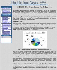
numerous general manufacturing components. Figure 1 summarizes the estimated<br />
US market distribution of ADI applications.<br />
FEATURES<br />
Cover Story - <strong>Ductile</strong> <strong>Iron</strong> <strong>Society</strong><br />
• receives the <strong>Society</strong>/Association of<br />
the Year Award - See Photos<br />
• Surface Defects in <strong>Iron</strong> Castings<br />
• Applications of ADI<br />
• Opportunities in Metal Casting<br />
• FEF College Industry Conference<br />
• Spectrometer Standards<br />
• AFS Trade Commission<br />
DEPARTMENTS<br />
• News Briefs<br />
• Advertisers<br />
• Back <strong>Issue</strong>s<br />
• DIS Home Page<br />
Figure 1 - Estimated US Market Distribution of ADI Applications (Courtesy of<br />
Applied Process Technologies Division)<br />
ADI APPLICATIONS AT FARRAR CORPORATION<br />
Farrar Corporation has successfully converted a number of components to ADI.<br />
According to Don Reimer, their customers are taking advantage of the near net<br />
shape technology of the casting process as well as the unique properties of ADI.<br />
Figure 2 shows a side link pusher dog for overhead conveying equipment that was<br />
converted from a steel forging. This ADI component was a significant cost savings<br />
for the end user because the lubricating hole could be cast in rather than machined<br />
into a forging
Figure 2: A side link pusher dog for overhead conveying equipment. (Courtesy of<br />
Farrar Corp.)<br />
Since this initial successful program, Farrar has continued with additional<br />
conversions to ADI in overhead conveyor systems along with numerous<br />
construction equipment applications. Figure 3 shows another ADI component in<br />
trenching equipment.<br />
Figure 3 - ADI gear in trenching Equipment. (Courtesy of Farrar Corporation)<br />
AN ADI ALTERNATIVE FOR A HEAVY DUTY TRUCK LOWER CONTROL ARM<br />
Daimler Chrysler Corporation's experience with the development of lower control<br />
arm for a heavy duty Dodge Ram pickup truck was chronicled by Phil Seaton.<br />
While the use of aluminum for substitution of ductile iron seems to be the<br />
emphasized for weight reduction purposes, the use of ADI is being considered<br />
because it has 3 times the strength of aluminum and 2.3 times the stiffness.<br />
Figure 4 shows both the stamped steel welded design along with the ADI<br />
alternative that was considered for this application. The final results showed a<br />
reduction in weight of 4 pounds per vehicle in addition to a significant reduction in<br />
tooling costs for the ADI control arm. However, the steel component was chosen<br />
over ADI because the ADI component was not ready in time for mandatory vehicle<br />
testing. Although ADI was not chosen in this instance, Seaton was confident that<br />
the advantages of using ADI were clearly demonstrated by this exercise.<br />
Figure 4 - The stamped steel welded (left view) and the ADI (right view) lower<br />
control arms for a heavy duty Dodge Ram pickup truck. (Courtesy of Intermet<br />
Corporation and Daimler Chrysler Corporation.)<br />
AGRICULTURAL APPLICATIONS OF ADI<br />
Applications ranging from gears to suspension and driveline components for<br />
agricultural applications were featured by Kristin Brandenberg of Applied Process<br />
Technologies Division. Once again, the near net shape aspects of using a casting<br />
along with the properties of ADI such as strength to weight ratio, toughness and<br />
wear resistance were listed as reasons for conversions.<br />
Figure 5 shows the lower control arm on the independent front suspension for a<br />
John Deere 8020 series large-row crop tractor. This 145 lb. casting not only cost<br />
less to manufacture, but weighed significantly less than the proposed forging.<br />
Figure 5 - ADI Control Arm for AWD Tractor (courtesy of<br />
John Deere)<br />
Carbidic ADI (CADI) which consists of ausferrite with a
controlled volume fraction of carbide present was also<br />
discussed for its growing interest for agricultural<br />
applications. This material shows improved wear<br />
performace over ADI along with impact properties that can<br />
be several times that of abrasion resistant irons. Figure 6 shows a CADI plow point<br />
that has been in production since the early 1990's.<br />
Figure 6 - ADI Plow Point (Courtesy of Carroll Ag)<br />
THIN WALL ADI IN ARGENTINA<br />
The use of ADI for thin-wall, high strength parts was<br />
explored by Martinez et al. It was pointed out that the<br />
casting process for producing thin wall components is<br />
more complicated and that casting quality is paramount for success in this type of a<br />
program. The production of a hollow connecting rod (<strong>No</strong>te Figure 7.) for an<br />
innovative two cylinder engine that generates 55 hp at 5500 rpm was shown. The<br />
thickness of the main portions of the part were as small as 3 mm which allowed for<br />
a weight reduction of 600 gms for a steel forging to a 400 gm ADI connecting rod.<br />
Figure 7 - A hollow connecting rod developed in Argentina.<br />
(Courtesy of INTEMA, Argentina)<br />
These connecting rods were assembled in prototype<br />
engines and were extensively tested in service with<br />
excellent results. This new engine with the hollow<br />
connecting rods has been presented in several national and<br />
international expositions in Argentina.<br />
SUMMARY<br />
ADI has become a material of choice for applications for a<br />
number of reasons that include the following:<br />
High strength to weight ratio<br />
Toughness<br />
Wear resistance<br />
Near net shape casting advantages<br />
The applications of ADI featured in this article represent only a small sample of<br />
those presented at the <strong>2002</strong> World Conference on ADI. Additional information can<br />
be found in the conference proceedings.<br />
FOR MORE INFORMATION<br />
Copies of the Proceedings of the <strong>2002</strong> World Conference on ADI cosponsored by<br />
the DIS and AFS can be purchased on-line from the American Foundry <strong>Society</strong> at<br />
www.afsinc.org.<br />
View<br />
<strong>Ductile</strong> <strong>Iron</strong> Related<br />
Publications<br />
Located in Strongsville, Ohio, USA<br />
15400 Pearl Road, Suite 234; Strongsville,Ohio 44136<br />
Billing Address: 2802 Fisher Road, Columbus, Ohio 43204<br />
Phone (440) 665-3686; Fax (440) 878-0070<br />
email:jwood@ductile.org
As a representative of this latter group I am honored to have been invited<br />
To Promote the production and application of ductile iron castings <strong>Issue</strong> 3, <strong>2002</strong><br />
Opportunities in Metal Casting<br />
Address to <strong>2002</strong> FEF College Industry Conference <strong>No</strong>v 8, <strong>2002</strong>.<br />
Roger Stanbridge. President and CEO. Foseco Metallurgical Inc.<br />
Cleveland, Ohio.<br />
This is an interesting time to speak to a group of young people preparing to<br />
enter the workplace. It is a time of change and uncertainty in almost all<br />
segments of the economy. The Foundry industry is no exception. It faces<br />
many of the same challenges as other industries, and some unique<br />
challenges of its own. As we shall see, it also presents some unique<br />
opportunities, which can be exploited through good management and<br />
through the contributions of talented and well-motivated people. I believe<br />
some of those people are here today and that they can look forward to<br />
successful careers in a successful industry.<br />
What is the Foundry Industry?<br />
It is certainly not homogeneous.<br />
FEATURES<br />
Cover Story - <strong>Ductile</strong> <strong>Iron</strong> <strong>Society</strong><br />
• receives the <strong>Society</strong>/Association of<br />
the Year Award - See Photos<br />
• Surface Defects in <strong>Iron</strong> Castings<br />
• Applications of ADI<br />
• Opportunities in Metal Casting<br />
• FEF College Industry Conference<br />
• Spectrometer Standards<br />
• AFS Trade Commission<br />
DEPARTMENTS<br />
• News Briefs<br />
• Advertisers<br />
• Back <strong>Issue</strong>s<br />
• DIS Home Page<br />
Around 3000 Foundries in USA and Canada with from 2 to 2000<br />
employees.<br />
Supplying products which sell from a few cents to thousands of<br />
dollars per pound<br />
Serving markets as diverse as agricultural tractors and medical<br />
implants, iron ore mining equipment and computers, aerospace<br />
turbines and oil platforms, machine tools and pressure cookers.<br />
Railroad cars and race cars. In fact there are very few nooks and<br />
crannies of the <strong>No</strong>rth American economy, which can function<br />
without a reliable source of cast parts.<br />
Casting metals and alloys as different as steel and magnesium,<br />
bronze and titanium, iron and aluminum. In fact the range of alloys<br />
cast in the foundry industry is estimated to employ, by design, as<br />
many as 51 elements, or 44% by number of the elements in the<br />
periodic table…. And by happenstance up to 5% more.<br />
As different as the jobbing foundry with thousands of patterns and<br />
capable of delivering a single casting to a unique specification and<br />
the highly focused repetition foundry producing castings of nearly<br />
identical form and function in the hundreds of thousands.<br />
About the only generic statement defining the industry is that all of its<br />
participants manage processes for converting molten metal into new solid<br />
shapes… and must succeed at it by adding value which exceeds by as much<br />
as possible the cost of doing so.<br />
Where do foundry suppliers fit in?<br />
The Foundry Industry also includes a strong and active base of suppliers of<br />
raw materials, process consumables, production equipment, and services…<br />
many of whom are dedicated to serving only the special needs of metal<br />
casting processes and all of whom must succeed by enabling their<br />
customers to add more value at lower cost.
to address you today and to discuss with you opportunities in the full<br />
breadth of the activities of the industry.<br />
The suppliers who work closely as part of the industry are challenged to<br />
participate in the change processes which are transforming the nature of the<br />
business, and in many cases we can help drive those changes. We have<br />
unique opportunities on a daily basis to observe the forces which are<br />
reshaping the industry. To be successful we must understand, and<br />
preferably anticipate, the real needs of our customers. We must have<br />
detailed understanding of the demands of our customers' customers, of the<br />
nature of external environmental and regulatory issues impacting the<br />
industry, and of the many sophisticated process technologies which are<br />
applied in castings production. Most important….. we must understand<br />
how to favorably influence the overall economics of making castings. How<br />
can we help our customer to make a casting at lower cost, or better , to<br />
make a casting of higher value. In such a diverse industry these are tough<br />
and complex challenges, but facing them in partnership with customers is<br />
both rewarding and enlightening. This enlightenment leads to some firm<br />
views on the future of the industry, the business strategies which will lead<br />
to success and, of interest to many of you here today, the keys to forging a<br />
rewarding career in the industry. I intend to share these views with you<br />
today.<br />
But first, I would like to tell you a little about the specific part of the<br />
foundry business I know best. Most of you who have spent any time in a<br />
foundry will recognize the Foseco name. It is attached to many products,<br />
which are integral to the manufacture of steel, iron, and non-ferrous<br />
castings.<br />
The Foseco culture<br />
In the USA and Canada Foseco is 350 people focused on making more<br />
profits for our foundry customers<br />
Our #1 priority is Innovation. We invented most of what we sell and much<br />
of the application technology which makes it work. We have a strong<br />
commitment to R and D.<br />
Just a few examples of what we do, including some more recent<br />
developments:<br />
Feeding systems…. Started by Foseco decades ago, but still a<br />
continuously evolving technology to enhance yield, quality, and<br />
productivity . Recent developments include high efficiency "spot<br />
feeders" for ductile iron castings, and patented direct pour systems<br />
for steel, iron and aluminum. The direct pour technology enables<br />
complete elimination of conventional gating systems for many<br />
castings… resulting in dramatic yield and productivity gains.<br />
Filtration …. Foseco introduced filtration technology to foundries.<br />
Filtration has revolutionized the production of high volume iron<br />
castings… providing higher yield, reduced scrap, more consistent<br />
mechanical properties, and better machinability. These advantages<br />
are now being extended to high volume aluminum castings, with<br />
unique products for these applications, and we are proving that the<br />
reduced mold filling turbulence predicted by simulation studies is real<br />
and that filtering with the right products offers major quality<br />
improvements beyond inclusion removal. The Holy Grail of steel<br />
castings filtration…. economic inclusion removal for carbon steel<br />
castings, plus priming and reliable flow without superheat… has been<br />
found. New Foseco Steel filter technology is now being introduced
which meets these critical needs.<br />
Insulating ladle lining systems for Steel and for <strong>Iron</strong>. Another Foseco<br />
innovation which provides the benefits of precise pouring<br />
temperature control, reduced tap temperature, reduced non-metallic<br />
inclusions, and major energy savings.<br />
<strong>Iron</strong> Stream Inoculation systems which combine patented dispensing<br />
equipment and purpose designed stream inoculating alloys to deliver<br />
consistent metallurgical performance and tight process control.<br />
Degassing systems for Aluminum, with patented rotor designs. <strong>No</strong>w<br />
augmented by the development of on-line hydrogen measurement<br />
and real-time process control.<br />
Products for the rapidly growing Lost Foam casting process. Foseco<br />
is intimately involved in this technology-intensive market. We supply<br />
consumable lost foam patterns and coatings. In fact Foseco is by far<br />
the largest supplier of externally sourced patterns to <strong>No</strong>rth American<br />
lost foam foundries. Here again innovation is a key strength… with<br />
our unique ventless pattern technology and patented copolymer<br />
pattern materials which have helped to solve the problem of lustrous<br />
carbon inclusion defects in Lost Foam iron casting.<br />
Application Engineering and simulation software for feeding and<br />
gating system optimization and for filter selection and placement. In<br />
addition to on-site technical support we provide our customers with<br />
the tools they need to obtain maximum economic gain from investing<br />
in our products.<br />
These are products…. but we know that our real business strength is our<br />
people and the commitment of those people to the single goal of improving<br />
our customers' businesses.<br />
A business is defined by its culture and its values…they set behavioral<br />
expectations which transcend organizational issues. Ours:<br />
Focus on customer needs.<br />
Innovate through customer partnerships<br />
Invest in R and D<br />
Think global, act local<br />
Be flexible, move fast<br />
Hire the best people, give them the best training,… then expect them<br />
to think and empower them to act.<br />
The best people, for Foseco, has included a large number of FEF alumni.<br />
Some have passed through the Foseco organization and gone on to success<br />
in other roles in the industry. Some have joined us after gaining experience<br />
with foundries. And some have started their careers with us and developed<br />
their careers to date in our organization. I know that all have contributed<br />
greatly to our business and to the industry as a whole. A recent count<br />
showed that we currently have 9 FEF alumni in the Foseco organization. I<br />
personally had a tough act to follow around 4 years ago when I succeeded<br />
an FEF alumnus as CEO here. In addition Foseco continues to actively<br />
support the FEF internship program. In the past 10 years approximately 30<br />
FEF students have interned at our <strong>No</strong>rth America headquarters in<br />
Cleveland, and a number of these were subsequently recruited to start their<br />
careers with us. We like to think that we can provide a very valuable<br />
opportunity to overview the way the industry works effectively with its<br />
suppliers in the development and application of manufacturing technology.<br />
That's our culture. There are a lot of different business cultures discernable<br />
in our customer base, but interestingly many of the most successful foundry<br />
organizations seem to share many of our core values. Of course, it could<br />
also be true that we have learned that to be successful we must emulate the
ehavior of our successful customers. After all, the starting point for every<br />
successful partnership is willingness to listen and learn and we train our<br />
people to be good listeners.<br />
Challenges and opportunities.<br />
Enough philosophy… what can we say about the immediate prospects for<br />
the foundry industry in <strong>No</strong>rth America? Is it a good place to start a career ?<br />
Firstly, we all know that the manufacturing sector has suffered<br />
disproportionately in the economic slowdown of the past 2-3 years. We<br />
also know that capital goods markets, which are important consumers of<br />
castings, have been and continue to be the weakest sector of the economy.<br />
After very strong demand in the latter half of the 90s the foundry industry<br />
here has hit a deep trough. Consumer markets, notably autos and housing,<br />
have held up better and castings demand from these segments has served to<br />
prop up the numbers. However some independent foundries have found it<br />
difficult to deal with the price-down demands of high volume customers, so<br />
that even relatively busy foundries have failed to deliver the profits<br />
expected by their owners, shareholders, and lenders. There have been<br />
business failures, bankruptcies, and closures throughout the industry. Some<br />
of these wounds were self-inflicted … consequences of over-expansion,<br />
acquisitions made at costs, which now seem unrealistic, and balance sheets<br />
loaded with debt, which could not be serviced. In some cases we have<br />
simply seen the law of the capitalist jungle in action…the best-managed<br />
foundries survived and their weaker brethren, who could live only in an<br />
environment where demand exceeded supply, have perished.<br />
As castings markets begin to recover there remain some major challenges<br />
for those foundries, which have survived:<br />
The challenge of globalization. Many castings for domestic<br />
consumption and which were previously sourced here are now<br />
coming from so-called "low cost" economies… China, Mexico,<br />
Brazil, South Africa, India, and Eastern Europe have all increased<br />
their castings shipments to our market. A long period with a strong<br />
US dollar has accelerated this process. In addition some global USAbased<br />
capital goods companies - in such markets as construction<br />
equipment, agricultural equipment, mining equipment, and oil<br />
exploration equipment - have found it attractive to move what was<br />
formerly export production to offshore locations in or closer to end<br />
markets. A loss of indirect export castings business.<br />
The challenge of regulatory compliance. The Foundry Industry is a<br />
major recycler... recycling is built into foundry process technology.<br />
The industry should be beloved to both the scientific and the<br />
emotional environmental communities. Unfortunately this is not<br />
always so. Our legislators continue to pile-on, with wave after wave<br />
of well intentioned, but muddle-headed, new initiatives. The Foundry<br />
Industry has complied proactively and responsibly with its<br />
obligations to the global community. But nothing will be gained if a<br />
quest to make basic process industries look like Wal-Mart's results in<br />
production moving offshore to locations where jobs are still more<br />
important than the green credentials of legislators. Nevertheless in<br />
order to do business here our industry must deal with these issues<br />
effectively, and must do so during a time when capital resources are<br />
scarce.<br />
The challenge of pressure on castings prices. The customers of<br />
both captive and independent foundries are under continuous<br />
pressure to reduce their costs in order to maintain competitive
position and meet their financial performance goals. This is translated<br />
down the food chain to insistence on lower prices for castings. This<br />
is not new, but it has become more intense during the economic<br />
slowdown and is now being leveraged by the threat of offshore<br />
sourcing and by the use of Internet auction processes. US industry<br />
has a strong record of driving down costs through increased<br />
productivity. Customer and competitive pressures are great stimuli<br />
for the productivity gains, which benefit the overall health of the<br />
economy. However many foundries now realize that each added<br />
percentage point in price reduction is more difficult than the previous<br />
one.. The learning curve on a given casting must eventually flatten, at<br />
which point the rules of the game must be changed or the game will<br />
be lost.<br />
Reviewing the background to the successful design, and production rampup<br />
of the many castings which have been featured in the past two years<br />
Those are just some of the challenges, and they all sound like really bad<br />
news.<br />
However, by examining how successful foundries are responding to this<br />
environment we can see that there is lots of really good news about the<br />
future of the industry.<br />
To see the model for success we have to look no further than some of<br />
the outstanding products being conceived and delivered by US and<br />
Canadian foundries. There are plenty of examples to consider…. Just<br />
a few of them can be seen in those nominated and recognized in the<br />
"Casting Design of the Year" process which has been sponsored by<br />
the AFS Marketing Services Division over the past two years.<br />
Let's look at a few examples.<br />
A ductile iron one-piece agricultural combine air-scoop produced by<br />
Neenah Foundry. This 25 lb cast component was converted from a<br />
complex weldment. A stronger and simpler design, which reduced<br />
the customer's net cost by 40%.<br />
This year's winner.. a magnesium casting developed as a housing for<br />
a computer graphics projector and produced by Prototype Casting<br />
Inc. of Denver. A spectacular thin wall casting developed to provide<br />
needed thermal stability in an application traditionally fulfilled by<br />
injection-molded plastic.<br />
A ductile iron casting produced by Aarowcast of Shawano Wisconsin<br />
is another excellent example. This is a two-piece 530 lb casting used<br />
in Caterpillar agricultural tractors. The casting replaced a 38 piece<br />
steel fabrication design, providing lower cost, higher strength, and<br />
improved appearance.<br />
A two-piece cast steel articulated hinge produced by Grede<br />
Milwaukee Steel Division. This is a component in specialty logging<br />
equipment and it was formerly a welded assembly of no less than 65<br />
parts. The cast design reduced assembly time and approved<br />
component performance.<br />
A ductile iron exhaust manifold produced for Mazda by Wescast.<br />
This thin-wall casting, made in greensand, was redesigned by<br />
Wescast and replaced a multiple weld stainless steel tube fabrication<br />
at 50% cost savings to the customer.<br />
These are just a few typical examples of the innovation, technical<br />
excellence, process management skills, and partnership ethos, which the<br />
people in the <strong>No</strong>rth American foundry industry are applying to their<br />
businesses.
serves to highlight the effective use which successful foundries are making<br />
of sophisticated computer techniques for predicting the results of thermal<br />
and physical stress , for simulation of mold fill and solidification, and for<br />
rapid prototyping. Many of these castings also involved the creative<br />
contributions from a whole spectrum of foundry suppliers, from software<br />
developers, to consumables companies and equipment suppliers.<br />
Delivering more profit for a customer is not limited to high volume,<br />
design intensive, castings. There are a number of very successful<br />
short run jobbing foundries which have developed business models<br />
built on fast response times for existing patterns and for new limited<br />
production castings… often in specialized alloys and including<br />
coordination of third party heat treating and machining services.<br />
These foundries have developed packages of skills and customerfriendly<br />
services providing end-to-end value which eliminates the<br />
"$s per pound" quoting treadmill.<br />
Success is also not limited to foundries with external customers. For<br />
example, the story of GM Powertrain Division development of the<br />
high performance Vortec series of aluminum light truck engines first<br />
unveiled in the wildly successful new Trailblazer SUV has been well<br />
documented. Concurrent design of a revolutionary new engine, and<br />
the foundry for production of its primary castings in the lost foam<br />
process which was chosen, is a remarkable achievement. The science<br />
of casting, and the contributions the dedicated manufacturing<br />
engineers who applied that science, are at the core of one of the most<br />
commercially important projects undertaken by GM.<br />
Environmental and regulatory challenges are being met head-on by<br />
foundries who have embraced the position that good environmental<br />
impact is good business and improved working conditions pay big<br />
dividends. For example, there is a surge of investment in cleaning<br />
room automation. In the new generation of cleaning rooms entrylevel<br />
foundry production employees need no longer be challenged by<br />
physically demanding labor. Many of the most progressive foundries<br />
have set environmental goals far exceeding those required or<br />
contemplated by regulation and have invested capital resources<br />
whose justification is founded in the belief that well managed<br />
foundry operations will continue to play a vital role in the economy.<br />
Lots of good news…. all involving foundries succeeding by applying<br />
innovation to their casting processes and their business processes in order<br />
to deliver increased profits for their external or internal customers. There<br />
are hundreds of such stories developing daily in US foundries. What do<br />
they tell us about the future?<br />
They tell us that castings markets are not limited solely to those<br />
applications whose have traditionally been met by castings.<br />
They tell us that the future is not in doing the same things in the<br />
same way. Absence of change is a prescription for being<br />
commoditized out of business. There is no casting which can not be<br />
improved to provide more value…. Just look at what Waupaca<br />
Foundry is doing in development of compacted graphite iron as a<br />
material for severe service truck brake drums. A simple "commodity"<br />
casting becomes a lighter, stronger, more durable component… much<br />
more valuable to the truck builder than a 20% price cut from a<br />
Chinese foundry.<br />
They tell us that the performance of foundries has to be measured in<br />
terms of value added for customers, not in terms of tonnage<br />
produced. The days when a good foundry business consisted of<br />
making more tonnage of the same castings, to the same<br />
specifications, and with the same performance as 5 or 10 years ago,
are long gone. Those are commodity castings, or soon will be. The<br />
offshore producers can make those castings, and will be pleased to do<br />
so at prices 5%, 10%, or 20% below ours. If we let our customers<br />
believe that is what they need, that may be what they will buy. To<br />
participate in that "commodity" segment US foundries should<br />
probably be operating, or outsourcing, offshore.<br />
They tell us that success lies in partnering with customers, and with<br />
suppliers. Good profitable foundry business is being established by<br />
US foundries who are collaborating with their customers in design<br />
and development of cast components, and with their suppliers in<br />
innovative process technology to optimize the performance and<br />
production cost of those castings. At Foseco we are privileged to<br />
work with many of the foundries whose business models are<br />
delivering success. We have the opportunity to see successful US<br />
foundry people at work.. and it is impressive.<br />
Offshore "price per pound" casting suppliers can not compete with<br />
customers who want to be served under the new rules .The new rules<br />
demand close, responsive, continuous and iterative communications<br />
between casting customer, casting producer, and suppliers.<br />
Innovative and well-managed <strong>No</strong>rth American foundries will thrive<br />
in this environment.<br />
In a moment we can look at what this all means for those of you who here<br />
because you are serious about embarking upon careers in this industry.<br />
First, we should recognize that there are other options for application of an<br />
expensive education and maybe a few comparisons are in order. After all,<br />
how can this ancient industry be compared favorably to the excitement,<br />
which is available in the go-go worlds of telecom, energy trading, media<br />
conglomerates, and creative auditing?<br />
Let us call them the "New Economy" businesses.<br />
A few specific comparisons for your consideration.<br />
Top Ten clues to tell you whether you are working in a Foundry or in a<br />
New Economy cubicle.<br />
Clue #1<br />
In the Foundry: You can labor hard for 10 years and get to be a Foundry<br />
Manager.<br />
In the Cube: You can make Chief Financial officer in just 6 months…<br />
then do 10 years hard labor.<br />
Clue #2<br />
In the Foundry: You have the opportunity to market near net shape<br />
Investment Castings.<br />
In the Cube: You have the opportunity to market near net worthless<br />
Investments.<br />
Clue #3<br />
In the Foundry: You learn that increased burn rate is good. It means that<br />
you are getting steel castings through the cleaning room faster.<br />
In the Cube: You learn that increased burn rate can be bad. Pay those<br />
bonuses before the cash runs out!<br />
Clue #4<br />
In the Foundry: When you speak in public you are introduced by the AFS<br />
program chairman, after dinner.<br />
In the New Cube: When you speak in public you are introduced by…<br />
"Will the defendant please rise."?
Clue #5<br />
In the Foundry: You are protected in the workplace by your hardhat and<br />
safety glasses<br />
In the Cube: You are protected in the workplace by the Fifth Amendment<br />
Clue #6<br />
In the Foundry: You can watch scrap melt down.<br />
In the Cube: You can watch your 401-K melt down.<br />
Clue #7<br />
In the Foundry: You will need Capital budgets for the melt shop,<br />
molding, and the cleaning room.<br />
In the Cube: You will need just one Capital budget… for paper shredders.<br />
Clue #8<br />
In the Foundry: You can learn how to improve business results by<br />
inventing products and processes.<br />
In the Cube: You can learn how to improve business results by inventing<br />
customers and sales.<br />
Clue #9<br />
In the Foundry: Charge sheet… generated by the Melt Shop<br />
Superintendent<br />
In the Cube: Charge sheet…. Generated by the Grand Jury foreman.<br />
And finally…<br />
Clue #10<br />
In the Foundry: Your parents can easily explain what you do to their<br />
friends.<br />
In the cube: They will have to explain why you have moved back into<br />
your old room.<br />
On the whole I think you will agree with me that the Foundry Industry, as<br />
part of the "New Old Economy" has more career attractions than some of<br />
these "New Economy" businesses. Boring is better… if it means owning<br />
real assets, making and selling real products to real customers, and<br />
employing people who are dedicated to personal growth through<br />
contributing to improvement of the economy and to the quality of life in<br />
their communities.<br />
In conclusion:<br />
The Foundry Industry holds a rewarding future for participants who<br />
know the elements of success:<br />
1. A focus on delivering profits for customers<br />
2. Innovation<br />
3. Leveraging technology<br />
4. Flexibility<br />
5. Development of Partnerships<br />
6. Hiring and developing the best people.<br />
This applies throughout the industry, to both producers and to<br />
suppliers.<br />
The Foundry Industry needs future leaders who are ready to thrive in<br />
this environment.<br />
There will be Big Prizes for the Winners<br />
You will make your own judgments on whether specific industry players<br />
are potential winners... one good clue is that the potential winners are likely<br />
to be recruiting from the ranks of FEF students.
I have enjoyed this opportunity to share some ideas with you. Good luck<br />
with your careers!<br />
View<br />
<strong>Ductile</strong> <strong>Iron</strong> Related<br />
Publications<br />
Located in Strongsville, Ohio, USA<br />
15400 Pearl Road, Suite 234; Strongsville,Ohio 44136<br />
Billing Address: 2802 Fisher Road, Columbus, Ohio 43204<br />
Phone (440) 665-3686; Fax (440) 878-0070<br />
email:jwood@ductile.org
To Promote the production and application of ductile iron castings <strong>Issue</strong> 3, <strong>2002</strong><br />
FEF College Industry Conference<br />
FOR IMMEDIATE RELEASE NOVEMBER, <strong>2002</strong><br />
FEF COLLEGE INDUSTRY CONFERENCE<br />
A total of 370 people-249 industry and university people attended this<br />
year's conference, along with 121 student delegates representing FEF's 32<br />
schools. This unique conference brought together top industry executives,<br />
FEF Board Members, Key Professors, university officials and top student<br />
delegates-all interested in metal casting. Bob Smillie of Nemak was the<br />
conference chairman.<br />
The FEF Annual Banquet was held at the Crystal Garden restaurant on<br />
Navy Pier in Chicago on Thursday night, <strong>No</strong>vember 7. Special FEF<br />
recognition awards were presented to: Foundry of the year-John Deere<br />
Foundry in Waterloo, Iowa; Supplier of the year-Fairmount Minerals in<br />
Chardon, Ohio; and <strong>Society</strong>/Association of the year-the <strong>Ductile</strong> <strong>Iron</strong><br />
<strong>Society</strong>. Also, at the banquet, FEF provided the forum for the Foundry<br />
Management & Technology's Hall of Fame awards which were presented<br />
to Paul Carey and Daryl Hoyt. Bruce Dienst of Simpson Technologies was<br />
the Master of Ceremonies.<br />
FEATURES<br />
Cover Story - <strong>Ductile</strong> <strong>Iron</strong> <strong>Society</strong><br />
• receives the <strong>Society</strong>/Association of<br />
the Year Award - See Photos<br />
• Surface Defects in <strong>Iron</strong> Castings<br />
• Applications of ADI<br />
• Opportunities in Metal Casting<br />
• FEF College Industry Conference<br />
• Spectrometer Standards<br />
• AFS Trade Commission<br />
DEPARTMENTS<br />
• News Briefs<br />
• Advertisers<br />
• Back <strong>Issue</strong>s<br />
• DIS Home Page<br />
During the General Session on Friday, the Keynote address was given by<br />
Roger Stanbridge, President of Foseco. This year's three panelists included<br />
Andrea Kay, Quality Engineer at EST Co., Grafton, WI and an FEF scholar<br />
from Ohio State and Virginia Tech; Pete Carpenter, Foundry Manager at<br />
Robert Bosch Corp., St. Joseph, MI and an FEF scholar from the Michigan<br />
Tech; and Bill Powell, Manager of Melt & Metallurgy of Waupaca<br />
Foundry, Waupaca, WI and an FEF scholar from the University of<br />
Wisconsin-Madison.<br />
During the Edward C. Hoenicke Memorial Luncheon, the AFS/FEF Board<br />
Award of $6000 was given to FEF Key Professor, Bob Voigt serving at<br />
Penn State University. Also given out this year, were 2 gifts, each in the<br />
amount of $10,000, from the FEF/Ray Witt Gift Program. These gifts were<br />
presented to Thomas Hahn from Pittsburg State University and Luis Trueba<br />
from Tri-State University.<br />
The Industry Information Session offered students an up-close and personal<br />
look at the industry. It also gave the 32 participating companies, who had<br />
33 tables, the most cost-effective way to see some of the top metal casting<br />
students in the country all in one place.<br />
The Awards and Recognition Breakfast speaker was the Chancellor of the<br />
University of Wisconsin-Milwaukee, Nancy Zimpher. Following her<br />
comments, 22 delegate scholarships were awarded to the student delegates<br />
who had submitted applications for these awards (see reverse side). In<br />
addition, one school had a student in the "runner-up" category. This<br />
student will receive an expense-paid trip to the AFS Government Affairs<br />
Conference in April, 2003. Also highlighted were the four Keith Millis
scholarships in <strong>Ductile</strong> <strong>Iron</strong> and the Ron Ruddle graduate level scholarship.<br />
FEF's highest award, the E.J. Walsh Award, was presented at this breakfast<br />
as well. The award went to Charter Lifetime Patron, Carl Loper, retired<br />
FEF Key Professor at the University of Wisconsin-Madison and current<br />
adjunct professor at the University of Wisconsin-Milwaukee.<br />
The total scholarships and awards that were presented during this 2-day<br />
conference equaled $85,000.<br />
Bill Sorensen, FEF's Executive Director, announced that next year's College<br />
Industry Conference will be in Chicago on <strong>No</strong>vember 13-15, 2003. More<br />
information on this conference, or any of the FEF activities, can be<br />
obtained from the FEF office at 484 E. <strong>No</strong>rthwest Highway, Des Plaines,<br />
IL 60016, Phone 847/299-1776, Fax 847/299-1789, email<br />
info@fefoffice.org, web page http://www.fefoffice.org.<br />
CIC Student Delegate Scholarships-<strong>No</strong>vember 9, <strong>2002</strong><br />
Richard Frazier Scholarship Travis Eastwood Pittsburgh State<br />
AFS Southwestern Ohio Scholarship Mark Reitz Ohio State<br />
William M. Grimes Schol.-Gartland<br />
Western Michigan<br />
David Spoon<br />
Foundry<br />
Univ.<br />
AFS Detroit-George Booth Scholarship Stefany Stankovic Univ. of Windsor<br />
Charles Marshall Memorial Scholarship Bodie Cooper Mississippi State<br />
John Svoboda Memorial Scholarship-<br />
Magma<br />
Alicia Cobb Missouri-Rolla<br />
James P. & Katherine Keating Scholarship Craig Murray Mohawk College<br />
Ron & Glenn Birtwistle Mem. Scholarship Bryan Orf<br />
Univ. of Wisconsin-<br />
Madison<br />
Ron & Glenn Birtwistle Mem. Scholarship Tiffany Thorbahn<br />
Univ. of Wisconsin-<br />
Milwaukee<br />
Tony & Elda Dorfmueller Scholarship Kate Felde Case Western Reserve<br />
Wm. E. Conway Schol.-Fairmount Minerals Joshua Mintz Pittsburgh State<br />
John Deere Scholarship Marcus Paar <strong>No</strong>rthern Iowa<br />
Robert W. Reesman Mem. Scholarship Jeffrey Schilz<br />
Univ. of Wisconsin-<br />
Platteville<br />
Burleigh Jacobs Scholarship-Grede Paul Hesse<br />
Univ. of Wisconsin-<br />
Platteville<br />
Donald G. Brunner Scholarship-Waupaca Christian Hansen<br />
Univ. of Wisconsin-<br />
Madison<br />
George Isaac Scholarship Nichlas Cannon Penn State<br />
Modern Casting Partners Scholarship Scott Zandarski Western Michigan<br />
Robert V. Wolf Mem. Scholarship Jennifer Garrison Missouri-Rolla<br />
Paul Carey Scholarship-Ashland Specialty Nicholas Nanninga Michigan Tech<br />
AFS-Saginaw Valley Scholarship Danielle Visser Michigan Tech<br />
Transportation Technologies Industries August Johnson Mississippi State<br />
Chester V. Nass Memorial Scholarship Justin Ladner Univ. of Alabama<br />
Runner-up<br />
(AFS Government Affairs Trip)<br />
Tyler <strong>No</strong>oyan Michigan Tech<br />
Special Scholarships also awarded at the breakfast<br />
Keith D. Millis Scholarship Tim Stanton Univ. of Wisconsin-Platteville<br />
Keith D. Millis Scholarship Matthew Thomas Purdue-West Lafayette<br />
Keith D. Millis Scholarship Andrew Szostak Bradley University<br />
Keith D. Millis Scholarship Coral <strong>No</strong>cton Tennessee Tech<br />
Ron Ruddle Memorial Scholarship Thomas Engle Case Western Reserve<br />
David Laine Scholarships<br />
Randall Bambenek-Wisconsin-Madison<br />
James Foreman-Tri-State Univ.
John Harm-Ohio State<br />
Dan Szablewski-Univ. of Windsor<br />
Dan Medvec-St. Thomas (Spring '02)<br />
View<br />
<strong>Ductile</strong> <strong>Iron</strong> Related<br />
Publications<br />
James Heller-Wisconsin-Platteville<br />
Nicole Weimer-Wisconsin-Madison<br />
Coral <strong>No</strong>cton-Tennessee Tech (Spring '02)<br />
Located in Strongsville, Ohio, USA<br />
15400 Pearl Road, Suite 234; Strongsville,Ohio 44136<br />
Billing Address: 2802 Fisher Road, Columbus, Ohio 43204<br />
Phone (440) 665-3686; Fax (440) 878-0070<br />
email:jwood@ductile.org
Photos from the<br />
FEF College Industry Conference<br />
Bill and Wendy Sorensen
Photos from the<br />
FEF College Industry Conference<br />
Bob and Linda Steele
Photos from the<br />
FEF College Industry Conference<br />
Ray Monroe's wife and Bob Voigt
Photos from the<br />
FEF College Industry Conference<br />
____________ and Bob Voigt
Photos from the<br />
FEF College Industry Conference<br />
Doyne and Linda Chartrau
Photos from the<br />
FEF College Industry Conference<br />
Clare and Jack Hall
Photos from the<br />
FEF College Industry Conference<br />
Jack Hall accepting<br />
the <strong>Society</strong>/Association<br />
of the Year award
Photos from the<br />
FEF College Industry Conference<br />
Paul Carey and Dean Peters
Photos from the<br />
FEF College Industry Conference<br />
Paul and Pat Carey
Photos from the<br />
FEF College Industry Conference<br />
Professor Doru Stefanescu<br />
and guest
To Promote the production and application of ductile iron castings <strong>Issue</strong> 3, <strong>2002</strong><br />
Spectrometer Standards<br />
Back to <strong>Issue</strong> 3, <strong>2002</strong> Index<br />
Overview of Spark Emission (OE)<br />
Instrumentation and Points to Consider<br />
Related to Cast <strong>Iron</strong> Analysis<br />
+<br />
"Spectrometer Standards/Samples<br />
for Spark Emission"<br />
Brad Cooley - OE Laboratory Manager - 313-271-5711<br />
(Revised from a Power Point Presentation)<br />
1. ThermoARL<br />
Thermo ARL - Founded in 1934<br />
Easy Operation<br />
Spark Excitation<br />
Simple Preparation<br />
Fast Analysis<br />
Majors to Traces<br />
Precise Results<br />
Accurate Results<br />
2. ThermoARL<br />
FEATURES:<br />
ARL Metals Analyzers<br />
1 Meter Focal Length Spectrometer<br />
Direct Reader (PMT Based)<br />
HiRep Source (400 Hz)<br />
Completely Enclosed Cabinetry<br />
BENEFITS:<br />
Optimum Line Choice/Resolution (in 1 cell)<br />
All Elements + C, P, S, N - High Performance<br />
Optimum Precision and Sensitivity<br />
Tolerates Rugged Environment<br />
3. ThermoARL<br />
Getting Good Results with Spark Emission<br />
Key Areas to Consider<br />
1. Sample Taking Procedures - Are they Consistent?
Quick Chill - Produces White Metallurgical Structure<br />
Homogeneity <strong>Issue</strong>s<br />
2. Sample Preparation - Method Used<br />
Dry vs. Wet Grinding<br />
Porosity Concerns<br />
3. Operator Technique<br />
4. Precision <strong>Issue</strong>s<br />
Sample Quality<br />
Argon Quality (99.995% min.)<br />
Preburn Time Long Enough? (Burn off Test)<br />
Instrument Precision Related to Concentration - What to Expect<br />
5. Accuracy <strong>Issue</strong>s<br />
Calibration<br />
a. Certified Reference Materials (CRM’s) Availability and Which<br />
Ones Used?<br />
b. Systematic Error - Bias<br />
c. Interference Correction<br />
Type Standardization<br />
6. Instrument Control<br />
SPC - Detect Problems<br />
Standardization - Corrective Action<br />
4. ThermoARL<br />
Sample Preparation - Spark Excitation (OE)<br />
Simple and Fast<br />
Provide Flat Surface<br />
Dry 60 Grit Al 2 O 3 or ZrO 2 40-120 Grit Size Acceptable<br />
Most Important to Remove surface scale, heavy oxides<br />
and/or oil residues<br />
5. ThermoARL<br />
SPARK STAND<br />
Water Cooled Table<br />
Quick, Easy Cleaning<br />
Heated Lens<br />
Low Ar Consumption<br />
Analysis Time
Optimizes Precision<br />
7. ThermoARL<br />
Spectrometer - Optical Light Path<br />
8. ThermoARL<br />
FEATURE:<br />
1 Meter Focal Length<br />
Temperature Controlled<br />
(Above ambient + 0.1 o )<br />
Shock Mounted<br />
Clean Vacuum System<br />
BENEFIT:<br />
Optimum Lines in 1 Cell<br />
Long Term Stability<br />
High Sensitivity and Stability<br />
SPECTROMETER<br />
9. ThermoARL<br />
Long-term Stability in<br />
Spark AES Analytical Importance<br />
Key influence on precision, accuracy and speed of analysis<br />
Time spent in optical profiling and drift correction is analytical time lost<br />
Frequent drift correction can contribute to error<br />
Metals production depends on stable analytical instruments to ensure<br />
the process is in control
10. ThermoARL<br />
Control Chart<br />
Integrated SPC<br />
11. ThermoARL<br />
Out of Control Limits<br />
SPC Rules<br />
12. ThermoARL<br />
Bias<br />
SPC Rules
13. ThermoARL<br />
Trend<br />
SPC Rules<br />
14. ThermoARL<br />
Precision Summary - ARL Spectrometer<br />
Short Term (n=10)<br />
Long Term - 48 hr (n=50)<br />
Element Sample Sample<br />
C 4.12 .0157 .38 4.12 .0176 .42<br />
Si 2.14 .0060 .28 2.15 .014 .65<br />
Mn .614 .0015 .24 .612 .0029 .47<br />
P .0246 .00025 1.0 .0247 .0004 1.6<br />
S .0062 .00015 2.4 .0060 .0002 3.3<br />
Ni 1.08 .0022 .21 1.09 .0030 .28<br />
Cr .0559 .00035 .21 1.09 .0030 .28<br />
Cr .0559 .00035 .63 .0571 .0004 .70<br />
Ti .0149 .00015 1.0 .0151 .0002 1.3<br />
V .578 .0020 .35 .579 .0031 .54
Cu .0251 .00015 .60 .0254 .0002 .61<br />
Al .044 .0003 .68 .045 .0003 .61<br />
Mg .078 .0018 2.4 .080 .0032 3.9<br />
B .0008 .000045 5.6 .0009 .000059 6.6<br />
Sn .0598 .0004 .67 .0601 .0007 1.2<br />
Pb .0032 .0002 5.7 .0031 .0002 6.4<br />
Average RSD: (*) 1.5 1.9(*)<br />
15. ThermoARL<br />
Long Term Stability<br />
Chilled Cast <strong>Iron</strong><br />
CAST IRON CONTROL SAMPLE WITHOUT STANDARDIZATION<br />
The global average precision of these elements over 5 days is 0.52 % RSD<br />
16. ThermoARL<br />
Long-term Stability<br />
Production Samples<br />
Steel Control Sample analyzed 2x each day in an actual<br />
working environment of a major steel company<br />
17. ThermoARL<br />
Spectrometer Standards/Samples For Spark Emission (Terminology Used)<br />
Standard / Sample Categories<br />
Uses<br />
Primary Standards*<br />
Certified Reference Material (CRM's)*<br />
Standard Reference Material*<br />
Calibration Standards*<br />
Reference Material (RM)^<br />
Type Standards*♦<br />
Secondary Standards<br />
Certificate of Analysis - Rigorous Testing*<br />
Used for Calibration of Instruments Only*<br />
Expensive and Limited*<br />
Less Rigorous Testing - Still Useful^<br />
To Fine Tune Instrument Calibration *♦<br />
To Correct For Instrument Changes Over Time<br />
Prerequisite is to be Homogeneous
Setting-Up Samples or Standards<br />
Drift Correction Samples or Standards<br />
Standardization Samples or Standards<br />
Re-Calibration Samples or Standards<br />
Control Samples or Standards<br />
Quality Control Samples or Standards<br />
Check Samples or Standards<br />
Good Intensity Spread (Low and High)<br />
Approximate Analysis Given<br />
To Monitor Instrument Performance at User Defined<br />
Time Intervals<br />
Should be Secondary Material - Homogeneous<br />
18. ThermoARL<br />
Certificate of Analysis<br />
STANDARD REFERENCE MATERIALS<br />
1140, 1141, 1142<br />
<strong>Ductile</strong> <strong>Iron</strong> Standards<br />
SRM <strong>No</strong>.<br />
1140<br />
1141<br />
1142<br />
<strong>Ductile</strong> <strong>Iron</strong> 1 <strong>Ductile</strong> <strong>Iron</strong> 2 <strong>Ductile</strong> <strong>Iron</strong> 3<br />
Element<br />
Percent<br />
Carbon 3.18 3.64 2.94<br />
Manganese 0.72 5 0.48 0 0.18 3<br />
Phosphorous .007 0 .073 .21 0<br />
Sulfur .010 .020 .015<br />
Sillicon 1.92 1.11 3.33<br />
Copper 0.096 0.20 4 1.02<br />
Nickel .028 .54 8 1.63<br />
Chromium .030 .13 8 .05 5<br />
Vanadium .030 .009 .006<br />
Molybdenum .09 5 .051 .023<br />
Titanium .09 6 .013 .008<br />
Aluminum (.01) (.005) .089<br />
Arsenic .07 2 .03 6 .01 0<br />
Magnesium .019 .044 .09 7<br />
Cerium (.09) (.05) (.015)<br />
Yttrium (
19. ThermoARL<br />
National Bureau of Standards<br />
Certificate of Analysis<br />
Standard Reference Material 1761<br />
Low-Alloy Steel<br />
(In Cooperation with the American <strong>Society</strong> for Testing and Materials)<br />
This Standard Reference Material (SRM) is in the form of a disk, approximately 34 mm (1 3/8 in) in diameter and 19<br />
mm (3/4 in) thick, and is intended for use in optical emission and x-ray spectrometric methods of analysis. SRM 2161<br />
is material from the same lot in the form of chips and is intended for checking chemical methods of analysis.<br />
Element Certified Value 1<br />
Percent by Weight<br />
Estimated 2<br />
Uncertainity<br />
Carbon 1.03 0.001<br />
Manganese 0.678 .005<br />
Phosphorus .042 .002<br />
Sulfur .035 .002<br />
Silicon .18 .01<br />
Copper .30 .01<br />
Nickel 1.99 .01<br />
Chromium 0.220 .005<br />
Vanadium .053 .002<br />
Molybdenum .103 .002<br />
Titanium .18 .01<br />
Arsenic .011 .002<br />
Aluminum (total) .06 .01<br />
Niobium .021 .001<br />
Zirconium .013 .001<br />
1 The certified value listed for a constituent is the present best estimate of the "true" value based on the results of the cooperative program for<br />
certification.<br />
2 The estimated uncertainty listed for a constituent represents an evaluation of the combined effects of method imprecision, possible systematic errors<br />
among methods, and material variability and is based on judgment. <strong>No</strong> attempt is made to derive exact statistical measures of imprecision because<br />
several methods were used in the determination of most constituents.<br />
The overall coordination of the technical measurements leading to certification was performed under the direction of<br />
J.I. Shultz, Research Associate, ASTM-NBS Research Associate Program.<br />
The technical and support aspects involved in the preparation, certification, and issuance of this Standard Reference<br />
Material were coordinated through the Office of Standard Reference Materials by W.P. Reed.<br />
February 24, 1998<br />
Gaithersburg, MD 20899<br />
Stanley D. Rasberry, Chief<br />
Office of the Standard Reference Materials<br />
20. ThermoARL<br />
Date: 6/7/<strong>2002</strong> 9:42:42<br />
MVR save state: CAIRMM32 2/19/2001 17:30:40<br />
Program:<br />
FECAIR.PRG<br />
Analysts:<br />
Mn3<br />
Correction Method:<br />
Base Curve<br />
Number of samples: 22<br />
Coefficients for base curves:<br />
Min: Max: AO: A1: A2: A3:
2.496 4.910 _6.73608a -30.35007 0.03228 0.00000<br />
Coefficients for interfering channels:<br />
------Sample------ Weight -Absolute Conc- -Difference-<br />
Name Number cps <strong>No</strong>minal Calc'd Absolute Percentage<br />
-----------------------------------------------------------------------------------------------------------------------------------------------------<br />
PURE 7RE-12 1.000 0.03055 1.00ppm 39.88ppm 0.00389 >500<br />
CKD 242 1.000 0.16808 0.04500 0.04907 0.00407 9.05<br />
CKD 249 1.000 0.40091 0.12700 0.12903 0.00203 1.60<br />
CKD 241 1.000 0.42135 0.13600 0.13658 0.00058 0.43<br />
BS 4C 1.000 0.57841 0.20700 0.19638 -0.01062 -5.13<br />
CKD 248 1.000 0.72074 0.24500 0.24392 -0.00108 -0.44<br />
CKD 243 1.000 1.0625 0.38500 0.37379 -0.01121 -2.91<br />
CTIF 2263/886 1.000 1.4513 0.53000 0.52736 -0.00264 -0.50<br />
CKD 244 1.000 1.7739 0.66500 0.66541 0.00041 0.06<br />
CTIF F03-1/8336 1.000 1.8169 0.68500 0.68768 0.00268 0.39<br />
CTIF 2249/A235 1.000 1.8739 0.70000 0.70118 0.00118 0.17<br />
CKD 239A 1.000 1.9721 0.74000 0.74462 0.00462 0.62<br />
CTIF F01-2/A172 1.000 1.9693 0.75000 0.75399 0.00399 0.53<br />
CTIF F06-2/83 1.000 2.0562 0.78000 0.78642 0.00642 0.82<br />
CTIF F04-1/8254 1.000 2.1140 0.81000 0.81840 0.00840 1.04<br />
BS 3C 1.000 2.4958 0.97800 0.97690 -0.00110 -0.11<br />
CKD 247 1.000 2.5325 1.01000 1.00905 -0.00095 -0.09<br />
CTIF F02-2/858 1.000 3.0256 1.25500 1.25381 -0.00119 -0.09<br />
CKD 245 1.000 3.2102 1.36000 1.34683 -0.01317 -0.97<br />
BS 1C 1.000 4.1356 1.78800 1.79112 0.00312 0.17<br />
CKD 235 1.000 4.1874 1.86000 1.85827 -0.00173 -0.09<br />
TURRET C7A 1.000 4.4636 2.05000 2.05224 0.00224 0.11<br />
Standard error of estimate: 0.00550<br />
21. ThermoARL<br />
STEEL SETTING-UP SAMPLES<br />
For DIRECT-READING SPECTROGRAPHS<br />
issued by<br />
Bureau of Analysed Samples, Ltd.<br />
Directors (1962-76):<br />
P.D. Ridsdale, B.Sc., M.I.M.<br />
(Managing)<br />
B. Bagshawe, A.Met., F.I.M.<br />
C. Gildon, F.C.A.<br />
INFORMATION SHEET SAMPLE "A/3" LOW ALLOY STEEL<br />
This sample has been prepared from a special cast of steel, representative sections of which have been thoroughly<br />
examined both spectroscopically and chemically to confirm the homogeneity of the bulk sample.<br />
APPROXIMATE COMPOSITION<br />
% %<br />
Carbon 0.03 Copper 0.04<br />
Silicon 0.01 Vanadium
standard figures.<br />
N.B. These samples should not be confused with the Primary Spectroscopic Standards prepared and issued by Bureau<br />
of Analysed Samples Ltd.<br />
Newham Hall, Middlesbrough, Cleveland, England March, 1976<br />
CKD Primary Standards - Low Alloy Cast <strong>Iron</strong> Calibrations<br />
ThermoARL<br />
23. ThermoARL<br />
24. ThermoARL
25. Back to top ThermoARL<br />
View<br />
<strong>Ductile</strong> <strong>Iron</strong> Related<br />
Publications<br />
Located in Strongsville, Ohio, USA<br />
15400 Pearl Road, Suite 234; Strongsville,Ohio 44136<br />
Billing Address: 2802 Fisher Road, Columbus, Ohio 43204<br />
Phone (440) 665-3686; Fax (440) 878-0070<br />
email:jwood@ductile.org
To Promote the production and application of ductile iron castings <strong>Issue</strong> 3, <strong>2002</strong><br />
FOR IMMEDIATE RELEASE<br />
<strong>No</strong>vember 19, <strong>2002</strong><br />
AFS TRADE COMMISSION<br />
505 State Street<br />
Des Plaines, Illinois 60016<br />
800/537-4237<br />
Fax: 847/824-7848<br />
www.afsinc.org<br />
AFS Trade Commission Recommends Section 332 Investigation<br />
as Next Step to Combat Offshore Competition<br />
Contact: Dwight Barnhard,<br />
dbarnhard@afsinc.org<br />
800/537-4237 x 222<br />
Des Plaines, Illinois . . .In a unanimous decision at its October 30 meeting,<br />
the American Foundry <strong>Society</strong> (AFS) Trade Commission approved the<br />
recommendation that the metalcasting industry pursue the filing of a<br />
Section 332 Fact-Finding Investigation with the U.S. International Trade<br />
Commission (ITC) at the earliest possible opportunity. This fact-finding<br />
study will provide a thorough overview of the U.S. metalcasting industry as<br />
well as review the conditions of competition between the U.S. industry and<br />
certain foreign countries. The final report, which will be issued by the ITC,<br />
documents facts, but makes no formal recommendations; however, it is the<br />
foundation for all future trade action at the federal level by the industry as a<br />
whole or individual segments of it.<br />
FEATURES<br />
Cover Story - <strong>Ductile</strong> <strong>Iron</strong> <strong>Society</strong><br />
• receives the <strong>Society</strong>/Association of<br />
the Year Award - See Photos<br />
• Surface Defects in <strong>Iron</strong> Castings<br />
• Applications of ADI<br />
• Opportunities in Metal Casting<br />
• FEF College Industry Conference<br />
• Spectrometer Standards<br />
• AFS Trade Commission<br />
DEPARTMENTS<br />
• News Briefs<br />
• Advertisers<br />
• Back <strong>Issue</strong>s<br />
• DIS Home Page<br />
"The Section 332 is an opportunity for the industry to better understand its<br />
future challenges, to create synergy and speak as one voice," said Chuck<br />
Kurtti, Commission chairman and AFS 2nd vice president.<br />
A Section 332 Investigation is conducted by the ITC, but will require the<br />
full cooperation of the metalcasting industry to allow the federal<br />
government body to provide a true picture of the present state of the U.S.<br />
industry. Individual companies will be requested to participate in a detailed<br />
survey by the ITC. These surveys will be the opportunity for each firm to<br />
provide evidence of the harm they are experiencing from foreign foundry<br />
competition.<br />
"This fact-finding option is being undertaken to answer questions about<br />
current trade conditions," said Dwight Barnhard, Commission member and<br />
AFS executive vice president. "The success of this effort will depend on<br />
industry participation during the initial data collection phase."<br />
The Section 332 investigation will be initiated by AFS as the industry<br />
representative. To facilitate the Section 332 Investigation and ensure the<br />
proper steps are taken with this filing, the AFS Trade Commission has<br />
retained the Washington D.C. law firm Collier Shannon Scott. This firm<br />
and its managing partner, Paul Rosenthal, have worked with both the<br />
municipal and water fitting segments of the casting industry on trade cases.<br />
The timeframe necessary for the completion of the Section 332<br />
Investigation is 12 months from the initiation date. It is expected that the<br />
legal costs associated with this investigation will be $100,000.
"In order to take this course of action, we need your financial support," said<br />
Kurtti. "We are seeking to collect funds from all the metalcasting sectors of<br />
our industry for this fact-finding investigation."<br />
The Trade Commission sent a letter to the entire metalcasting industry this<br />
month requesting financial assistance by December 15. For more<br />
information on this request, visit the AFS website at www.afsinc.org.<br />
The AFS Trade Commission was officially formed at the AFS Trade Forum<br />
in April to examine the issue of foreign competition and its impact on the<br />
U.S. metalcasting industry, and to determine the courses of action available<br />
to the industry at the federal government level. In pursuit of this,<br />
Commission members participated in a series of meetings with trade<br />
experts at the U.S. Dept. of Commerce, the ITC, lawmakers, congressional<br />
staff and trade lawyers. In addition, the Commission reviewed past and<br />
present trade actions by the whole and portions of the U.S. metalcasting<br />
industry.<br />
The members of the Commission are: Kurtti; Hugh Aiken, Atchison<br />
Casting Corp.; Dwight Barnhard, AFS; George Boyd, Goldens' Foundry &<br />
Machine Co.; Thomas Brown, Benton Foundry; Don Carpenter, U.S.<br />
Foundry & Manufacturing Co.; Paul Cervellero, Inductotherm Corp.; Jerry<br />
Donohue, <strong>No</strong>rth American Precision Casting; Jim Keffer, EBAA <strong>Iron</strong><br />
Sales, Inc.; James Larson, Waupaca Foundry, Inc., Dan Torzewski,<br />
Indianapolis Casting Corp.; Daniel Twarog, <strong>No</strong>rth American Die Casting<br />
Assn.; and Jack Zbiegien, Gregg Industries.<br />
For more information on the AFS Trade Commission and its actions,<br />
contact Chuck Kurtti, Neenah Foundry Co. (retired), at 920/725-0028 or<br />
ckurtti@new.rr.com, or Dwight Barnhard, AFS, at 800/537-4237 ext. 222<br />
or dbarnhard@afsinc.org.<br />
Headquartered in Des Plaines, IL, AFS is a not-for-profit technical and<br />
management society that has existed since 1896 to provide and promote<br />
knowledge and services that strengthen the metalcasting industry for the<br />
ultimate benefit of its customers and society.<br />
View<br />
<strong>Ductile</strong> <strong>Iron</strong> Related<br />
Publications<br />
Located in Strongsville, Ohio, USA<br />
15400 Pearl Road, Suite 234; Strongsville,Ohio 44136<br />
Billing Address: 2802 Fisher Road, Columbus, Ohio 43204<br />
Phone (440) 665-3686; Fax (440) 878-0070<br />
email:jwood@ductile.org
To Promote the production and application of ductile iron castings <strong>Issue</strong> 3, <strong>2002</strong><br />
MEETINGS<br />
News Briefs<br />
Reseach Committee Meeting: January 15 and 16, 2003 at Ramada<br />
O'Hare, Rosemont, IL (Chicago Area). Tower rooms requested.<br />
The June 2003 meeting will be held at The Woodlands Inn and<br />
Resort in Wilkes Barre, Pennsylvania on June 2-4, 2003.<br />
There will be a Keith Millis Symposium on October 20-23, 2003 at<br />
the Crowne Plaza Resort in Hilton Head Island, South Carolina.<br />
BUSINESS<br />
Columbus, Ohio (USA) - Ashland Specialty Chemical Company's<br />
Foundry Products Division announced today the creation of two new<br />
global business units, a new name for its overall business, and a new<br />
logo.<br />
FEATURES<br />
Cover Story - <strong>Ductile</strong> <strong>Iron</strong> <strong>Society</strong><br />
• receives the <strong>Society</strong>/Association of<br />
the Year Award - See Photos<br />
• Surface Defects in <strong>Iron</strong> Castings<br />
• Applications of ADI<br />
• Opportunities in Metal Casting<br />
• FEF College Industry Conference<br />
• Spectrometer Standards<br />
• AFS Trade Commission<br />
DEPARTMENTS<br />
• News Briefs<br />
• Advertisers<br />
• Back <strong>Issue</strong>s<br />
• DIS Home Page<br />
"For over a century, we've been a leading supplier of binders and<br />
consumables to the sand casting market," says Mike Swartzlander,<br />
vice president and general manager of the newly christened Ashland<br />
Casting Solutions. "To deliver increased value to customers, we have<br />
expanded our strategic focus beyond sand binder products to the<br />
entire metal casting process and new metal casting technologies.<br />
We've reorganized and renamed our business in line with our new<br />
identity."<br />
Two Global Business Units<br />
To better focus human and materials resources against customer<br />
challenges in its expanding markets, Ashland Casting Solutions will<br />
be organized into two global business units.<br />
The newly created Foundry Binder Solutions business unit will<br />
focus on Ashland's sand binder product lines and services and build<br />
on the company's worldwide technical leadership in cold box and<br />
binder systems. Greg MacIver has been named business director of<br />
Foundry Binder Solutions.<br />
In addition, a Metal Casting Specialties business unit will<br />
concentrate on the nonbinder metal casting consumables business.<br />
This organization will be responsible for existing refractory coatings,<br />
sand additives, core adhesives, releases, sleeves and filter lines as<br />
well as for leveraging Ashland's technological expertise into other<br />
casting areas such as lost foam, permanent mold, high pressure die,<br />
and investment casting. Philip Lipianka has been named director of<br />
Metal Casting Specialties.<br />
"I'm confident that these more focused business units will yield both<br />
operational and product benefits for customers," adds Swartzlander.<br />
"In most cases, the organizational changes will also be transparent to<br />
current customers. They will continue to be served by the same
salespeople and customer service representatives."<br />
New Casting Solutions Name and Company Logo Complement<br />
Structural Changes<br />
The organizational realignment and name change to Casting Solutions<br />
coincides with the launch of a new, more contemporary and dynamic<br />
logo for all of Ashland Specialty Chemical Company.<br />
About Ashland<br />
Ashland Casting Solutions, a business unit of Ashland Specialty<br />
Chemical Company, is a leader in supplying products, processes and<br />
technologies to the global marketplace for cold box sand binder<br />
systems and non-binder metal casting systems.<br />
Ashland Specialty Chemical Company, a division of Ashland Inc., is<br />
a leading, worldwide supplier of specialty chemicals serving<br />
industries including adhesives, automotive, composites, foundry,<br />
merchant marine, paint, paper, plastics, semiconductor, watercraft and<br />
water treatment. Visit the website www.ashspec.com to learn more<br />
about these operations.<br />
Ashland, Inc. is a Fortune 500 company providing products, services,<br />
and customer solutions throughout the world. Our businesses include<br />
road construction, specialty chemicals, lubricants, car-care products,<br />
chemical and plastics distribution and transportation fuels. Through<br />
the dedication of our employees, we are "The Who in How Things<br />
Work. TM " Find us at www.ashland.com.<br />
PEOPLE<br />
Milwaukee, Wisconsin - Grede Foundries, Inc., has named the<br />
following individuals as Vice Presidents: Tam Trudeau-Ebenhoeh<br />
for the Vassar foundry in Vassar, Michigan, Jeff Friday for the<br />
Liberty foundry in Milwaukee, Wisconsin, and Dave Roycraft for<br />
the New Castle foundry in New Castle, Indiana.<br />
Trudeau-Ebenhoeh joined Grede in 1991 at its Vassar foundry. Most<br />
recently, she served as Works Manager of the Vassar foundry.<br />
Friday joined Grede in 1992 at its Reedsburg foundry in Reedsburg,<br />
Wisconsin. Most recently, he served as Works Manager at its Liberty<br />
foundry.<br />
Roycraft joined Grede in 1999 also at its New Castle foundry as<br />
Factory Manager and became Works Manager in <strong>No</strong>vember, 1999.<br />
Grede Foundries operates foundries in the U.S. and the U.K., and is a<br />
recognized leading producer of high quality castings in gray iron,<br />
ductile iron, and steel.<br />
TROY, Mich., December 11, <strong>2002</strong> - INTERMET Corporation<br />
announced today that its Board of Directors elected Dr. Gary F.<br />
Ruff as President and Chief Operating Officer (COO) of the<br />
Corporation.<br />
Dr. Ruff most recently was Executive Vice President and a member<br />
of the Company's Operating Committee.
Chairman and CEO John Doddridge also announced that it is his<br />
intention to step down as Chief Executive Officer of the Company in<br />
July 2003, but remain as Chairman of the Board. Mr. Doddridge was<br />
elected Chairman and Chief Executive Officer of the Company in<br />
October 1994.<br />
TROY, Mich., December 16, <strong>2002</strong> - INTERMET Corporation<br />
announced that effective today, Thomas E. Prucha has been<br />
promoted to the position of Vice President, Technical Services, from<br />
Director, Process Research & Development. He reports to Dr. Gary<br />
F. Ruff, who recently was named President and COO of<br />
INTERMET. In addition, Prucha will be a member of the Corporate<br />
Operating Committee.<br />
Prucha's new responsibilities include oversight of INTERMET's<br />
research and development, materials, process and product engineering<br />
and development, environmental activities, and facilities engineering.<br />
Back to top<br />
View<br />
<strong>Ductile</strong> <strong>Iron</strong> Related<br />
Publications<br />
Located in Strongsville, Ohio, USA<br />
15400 Pearl Road, Suite 234; Strongsville,Ohio 44136<br />
Billing Address: 2802 Fisher Road, Columbus, Ohio 43204<br />
Phone (440) 665-3686; Fax (440) 878-0070<br />
email:jwood@ductile.org