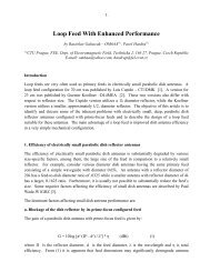
Feedhorn s kruhovou polarizacà pro parabolické antény - Ok1dfc.com
Feedhorn s kruhovou polarizacà pro parabolické antény - Ok1dfc.com
Feedhorn s kruhovou polarizacà pro parabolické antény - Ok1dfc.com

Create successful ePaper yourself
Turn your PDF publications into a flip-book with our unique Google optimized e-Paper software.
Feed-horn with circular<br />
polarization for parabolic<br />
dish<br />
Zdenek SAMEK – OK 1 DFC
Why septum transformer ?<br />
• Necessary use circular polarization over 1 GHz<br />
• Possibility use feed for LCP and RCP without 90° hybrid<br />
and TX-RX switching<br />
• Saving 1,5 dB on the RX and TX site<br />
• Saving money for expenses High power relay.<br />
• Advantage that between TX and RX sites are loss more<br />
then 26 dB<br />
• Good impedance adaptation both TX and RX ports<br />
• Very easy possible set up high SWR
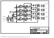
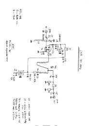
Electric diagram of septum<br />
VE 4 MA – W 2 IMU – system<br />
Septum-feed<br />
– OK 1 DFC<br />
v<br />
h<br />
Hybrid<br />
RX port<br />
TX port<br />
Relay for<br />
high power<br />
CX520 relay<br />
50R<br />
Preamp<br />
RX<br />
30W<br />
TX<br />
Preamp<br />
RX<br />
50R<br />
1W<br />
TX
How is it working ?<br />
L<br />
R<br />
TX<br />
RX<br />
TX<br />
RX<br />
V<br />
RCP<br />
H
Driving of transformer<br />
Vertical part of electromagnetic wave<br />
1 2 3<br />
1. Four-square wave guide on the feed input<br />
2. Septum transformer<br />
3. Rectangular wave guide in RX – TX part, very close to by<br />
connector
Driving of transformer<br />
Horizontal part of electromagnetic wave<br />
1 2 3<br />
1. Four-square wave guide on the input<br />
2. Septum transformer<br />
3. Rectangular part of RX and TX wave guide
A<br />
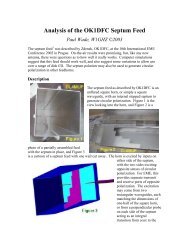
Parts of feed<br />
B<br />
C<br />
RX<br />
TX<br />
D1 – D2<br />
RX – connector for receiving cable<br />
TX – connector for transmitting cable<br />
D1 – D2 – <strong>com</strong>pensation capacitors for set up SWR<br />
A – Rectangular parts RX - TX<br />
B – Transformer<br />
C – For-square output wave guide
Circularity of polarization<br />
0 dB<br />
x -1,6dB -Diagram of circularity<br />
y<br />
-Theoretical maximum of<br />
discircurality is – 1,1 dB<br />
-With not correctly calculate<br />
septum transformer will be<br />
diagram as a „cake“
Measurement diagram in unreflecting chamber TX<br />
Smě rové charakteristiky ozařovač e Septum 2,3 GHz<br />
-20<br />
-25<br />
-30<br />
-35<br />
[dBm ]<br />
-40<br />
-45<br />
-50<br />
-55<br />
-60<br />
0 30 60 90 120 150 180 210 240 270 300 330 360<br />
[°]<br />
P kone ktor, rovina kolm á na kone ktory, vys íla ná Ve rt. pola riza ce , 2,3 GHz [dBm ]<br />
P konektor, rovina rovnobě žná s kone ktory, vys íla ná Ve rt. pola riza ce , 2,3 GHz, přívodní kabel na 270 st. [dBm]<br />
P konektor, rovina rovnobě žná s kone ktory, vys íla ná Hor. pola riza ce , 2,3 GHz, přívodní kabel na 270 st. [dBm]<br />
P konektor, rovina kolmá na konektory, vysílaná Hor. polarizace, 2,3 GHz [dBm]
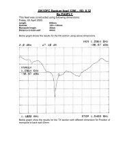
Measurement diagram in unreflecting chamber RX<br />
Smě rové charakteristiky ozařovače Se ptum 2,3 GHz<br />
-20<br />
-25<br />
-30<br />
-35<br />
[dBm]<br />
-40<br />
-45<br />
-50<br />
-55<br />
-60<br />
0 30 60 90 120 150 180 210 240 270 300 330 360<br />
[°]<br />
L konektor, rovina kolmá na konektory, vysílaná Vert. polarizace, 2,3 GHz [dBm]<br />
L konektor, rovina rovnobě žná s konektory, vysílaná Vert. polarizace, 2,3 GHz, přívodní kabel na 90 st. [dBm]<br />
L konektor, rovina rovnobě žná s konektory, vysílaná Hor. polarizace, 2,3 GHz, přívodní kabel na 90 st. [dBm]<br />
L konektor, rovina kolmá na konektory, vysílaná Hor. polarizace, 2,3 GHz [dBm]
Comments<br />
• We saw that circularity is absolutely perfect<br />
• Diagram was done for 2,3 GHz feed<br />
• Measurement condition-unreflecting chamber of Electrotechnician<br />
University Praha<br />
• Radiation angel 130° for –10 dB<br />
• Practical use for dish with 0.35 F/D<br />
• For other F/D is possible use with choking collar like<br />
VE4MA feed. Practical solution has Franta OK1CA
Practical calculation
Comments<br />
• We saw that calculation is in Excel very <strong>com</strong>fortable<br />
• All dimensions are in mm<br />
• Material for feed is Aluminum or Cooper sheet<br />
• Do not use bras, <strong>pro</strong>blem with freeze<br />
• For frequency up to 2.3 GHz accuracy up to 0,5mm<br />
• Higher frequency up to 0,1mm
Types of septum transformer<br />
1. 2.<br />
Sloping septum<br />
- isolation RX-TX 25 dB max.<br />
- discircurality 2 – 3 dB<br />
- easy for <strong>pro</strong>ducing<br />
Chen and Tsandoulas septum<br />
- isolation RX-TX up to 27,5 dB<br />
max.<br />
- Maximum of discircurality 1,1<br />
dB<br />
- Circularity for very wide<br />
frequency range +,- 10% of<br />
calculation frequency
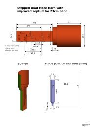
Practical solution of feed<br />
Feed for 1296 MHz – practical solution
Assembly of on the RX port for 1296 MHz
Assembly of feed – look to <strong>com</strong>pensation capacity screw.
Application of feed by OK 1 UWA for 1296 MHz
Feed with funnel by OK 1 CA for 2320 MHz and Cassegrain<br />
mirror
Thank you for your attention –<br />
GL and 73 !<br />
OK 1 DFC