- Page 1:
High Level Assembler for MVS & VM &
- Page 4 and 5:
Note! Before using this information
- Page 6 and 7:
Contents Source Module . . . . . .
- Page 8 and 9:
Contents Ordinary USING Instruction
- Page 10 and 11:
Contents Sublists in Operands . . .
- Page 12 and 13:
About this Manual This manual descr
- Page 14 and 15:
IBM High Level Assembler for MVS &
- Page 16 and 17:
| The Internet. You can access IBM
- Page 18 and 19:
▌C▐ The item referred to by ▌
- Page 20 and 21:
Miscellany The ASCII translation t
- Page 22 and 23:
Part 1. Assembler Language—Struct
- Page 24 and 25:
Language Compatibility Language Com
- Page 26 and 27:
Assembler Program Assembler Program
- Page 28 and 29:
Relationship of Assembler to Operat
- Page 30 and 31:
Coding Made Easier Linkage between
- Page 32 and 33:
Character Set Compatibility with Ea
- Page 34 and 35:
Assembler Language Coding Conventio
- Page 36 and 37:
Assembler Language Coding Conventio
- Page 38 and 39: Assembler Language Coding Conventio
- Page 40 and 41: Assembler Language Coding Conventio
- Page 42 and 43: Assembler Language Structure Condit
- Page 44 and 45: Assembler Language Structure Machin
- Page 46 and 47: Assembler Language Structure Condit
- Page 48 and 49: Terms, Literals, and Expressions Te
- Page 50 and 51: Terms, Literals, and Expressions -
- Page 52 and 53: Terms, Literals, and Expressions As
- Page 54 and 55: Terms, Literals, and Expressions Se
- Page 56 and 57: Terms, Literals, and Expressions Fo
- Page 58 and 59: Terms, Literals, and Expressions I
- Page 60 and 61: Terms, Literals, and Expressions Th
- Page 62 and 63: Terms, Literals, and Expressions 1.
- Page 64 and 65: Terms, Literals, and Expressions
- Page 66 and 67: Terms, Literals, and Expressions
- Page 68 and 69: Terms, Literals, and Expressions Th
- Page 70 and 71: | Chapter 3. Program Structures and
- Page 72 and 73: Source Module A source module is co
- Page 74 and 75: The CSECT instruction can be used a
- Page 76 and 77: | in linker control statements for
- Page 78 and 79: This is not only convenient, but it
- Page 80 and 81: | SECT_A CSECT , Define section SEC
- Page 82 and 83: | For executable sections, the loca
- Page 84 and 85: Addressing | The System/390® and z
- Page 86 and 87: Addressing | Parts must always be r
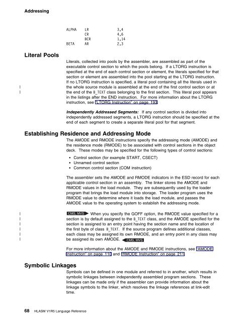
- Page 90 and 91: Addressing If the symbol is the nam
- Page 92 and 93: Addressing External Symbol Dictiona
- Page 94 and 95: Addressing 74 HLASM V1R5 Language R
- Page 96 and 97: Part 2. Machine and Assembler Instr
- Page 98 and 99: General Instructions Chapter 4. Mac
- Page 100 and 101: Input/Output Operations For further
- Page 102 and 103: Branching with Extended Mnemonic Co
- Page 104 and 105: Symbolic Operation Codes variations
- Page 106 and 107: Operand Entries Registers You can s
- Page 108 and 109: Operand Entries “Program Structur
- Page 110 and 111: Operand Entries Format │ Coded or
- Page 112 and 113: Examples of Coded Machine Instructi
- Page 114 and 115: Examples of Coded Machine Instructi
- Page 116 and 117: Examples of Coded Machine Instructi
- Page 118 and 119: Examples of Coded Machine Instructi
- Page 120 and 121: Chapter 5. Assembler Instruction St
- Page 122 and 123: *PROCESS Statement *PROCESS Stateme
- Page 124 and 125: ACONTROL Instruction ►►──
- Page 126 and 127: ACONTROL Instruction FLAG(PAGE0) in
- Page 128 and 129: AINSERT Instruction character_strin
- Page 130 and 131: AMODE Instruction alias_string is t
- Page 132 and 133: CATTR Instruction Figure 25. AMODE/
- Page 134 and 135: CATTR Instruction | statements for
- Page 136 and 137: CCW1 Instruction data_count is an a
- Page 138 and 139:
CEJECT Instruction If symbol is an
- Page 140 and 141:
CNOP Instruction Figure 29 (Page 2
- Page 142 and 143:
COPY Instruction In the following e
- Page 144 and 145:
CSECT Instruction symbol in the nam
- Page 146 and 147:
DC Instruction ROUTINE B GAMMA DXD
- Page 148 and 149:
DC Instruction duplication_factor c
- Page 150 and 151:
DC Instruction Figure 33 (Page 2 of
- Page 152 and 153:
DC Instruction With EBCDIC spaces
- Page 154 and 155:
DC Instruction Further information
- Page 156 and 157:
DC Instruction | Symbols used in su
- Page 158 and 159:
DC Instruction The length attribute
- Page 160 and 161:
DC Instruction Notes: 1. Don't conf
- Page 162 and 163:
DC Instruction—Character Constant
- Page 164 and 165:
DC Instruction—Character Constant
- Page 166 and 167:
DC Instruction—Graphic Constant r
- Page 168 and 169:
DC Instruction—Fixed-Point Consta
- Page 170 and 171:
DC Instruction—Fixed-Point Consta
- Page 172 and 173:
DC Instruction—Decimal Constants
- Page 174 and 175:
DC Instruction—Address Constants
- Page 176 and 177:
DC Instruction—Address Constants
- Page 178 and 179:
DC Instruction—Offset Constant re
- Page 180 and 181:
DC Instruction—Length Constant Le
- Page 182 and 183:
DC Instruction—Hexadecimal Floati
- Page 184 and 185:
DC Instruction—Hexadecimal Floati
- Page 186 and 187:
DC Instruction—Hexadecimal Floati
- Page 188 and 189:
DC Instruction—Binary Floating-Po
- Page 190 and 191:
DC Instruction—Binary Floating-Po
- Page 192 and 193:
DROP Instruction DROP Instruction T
- Page 194 and 195:
DS Instruction USING DSECTA,14 ALBL
- Page 196 and 197:
DS Instruction The size of a storag
- Page 198 and 199:
DSECT Instruction DSECT Instruction
- Page 200 and 201:
DXD Instruction ASEMBLY2 CSECT USIN
- Page 202 and 203:
END Instruction change but no addit
- Page 204 and 205:
EQU Instruction EQU Instruction The
- Page 206 and 207:
EQU Instruction 5. The length attri
- Page 208 and 209:
EXITCTL Instruction sequence_symbol
- Page 210 and 211:
ISEQ Instruction must be greater th
- Page 212 and 213:
LOCTR Instruction A CSECT , See not
- Page 214 and 215:
LTORG Instruction If symbol is an o
- Page 216 and 217:
MNOTE Instruction When two literals
- Page 218 and 219:
OPSYN Instruction ,ERROR, SEV 1 An
- Page 220 and 221:
ORG Instruction AFTER is defined in
- Page 222 and 223:
ORG Instruction If you specify mult
- Page 224 and 225:
POP Instruction POP Instruction The
- Page 226 and 227:
PRINT Instruction Note: If the next
- Page 228 and 229:
Process Statement Process Statement
- Page 230 and 231:
REPRO Instruction NOPRINT instructs
- Page 232 and 233:
RSECT Instruction 4. AMODE or RMODE
- Page 234 and 235:
START Instruction START Instruction
- Page 236 and 237:
TITLE Instruction The name value is
- Page 238 and 239:
USING Instruction Only the characte
- Page 240 and 241:
USING Instruction Base Registers fo
- Page 242 and 243:
USING Instruction If register 0 is
- Page 244 and 245:
USING Instruction A variable symbo
- Page 246 and 247:
USING Instruction In this MVC instr
- Page 248 and 249:
USING Instruction Range of a Depend
- Page 250 and 251:
XATTR Instruction external_symbol i
- Page 252 and 253:
XATTR Instruction SCOPE ►►─
- Page 254 and 255:
XATTR Instruction 234 HLASM V1R5 La
- Page 256 and 257:
Part 3. Macro Language &SYSDATC Sys
- Page 258 and 259:
Introduction to Macro Language Chap
- Page 260 and 261:
Introduction to Macro Language The
- Page 262 and 263:
Introduction to Macro Language Macr
- Page 264 and 265:
MACRO and MEND Statements The assem
- Page 266 and 267:
Prototype Statement Macros that are
- Page 268 and 269:
Model Statements generated from tha
- Page 270 and 271:
Model Statements ▌5▐ ▌6▐
- Page 272 and 273:
Model Statements Notes: 1. You can
- Page 274 and 275:
Positional Parameters Symbolic para
- Page 276 and 277:
Processing Statements Processing St
- Page 278 and 279:
AREAD Instruction Assign Local Time
- Page 280 and 281:
COPY Instruction sequence_symbol is
- Page 282 and 283:
System Variable Symbols System Vari
- Page 284 and 285:
&SYSADATA_MEMBER System Variable Sy
- Page 286 and 287:
&SYSCLOCK System Variable Symbol &S
- Page 288 and 289:
&SYSECT System Variable Symbol depe
- Page 290 and 291:
&SYSIN_MEMBER System Variable Symbo
- Page 292 and 293:
&SYSJOB System Variable Symbol &SYS
- Page 294 and 295:
&SYSLIN_DSN System Variable Symbol
- Page 296 and 297:
&SYSLIST System Variable Symbol The
- Page 298 and 299:
&SYSLOC System Variable Symbol To
- Page 300 and 301:
&SYSM_SEV System Variable Symbol &S
- Page 302 and 303:
&SYSNDX System Variable Symbol The
- Page 304 and 305:
&SYSOPT_DBCS System Variable Symbol
- Page 306 and 307:
&SYSPARM System Variable Symbol Not
- Page 308 and 309:
&SYSPRINT_MEMBER System Variable Sy
- Page 310 and 311:
&SYSPUNCH_MEMBER System Variable Sy
- Page 312 and 313:
&SYSSTEP System Variable Symbol Not
- Page 314 and 315:
&SYSTERM_DSN System Variable Symbol
- Page 316 and 317:
&SYSTIME System Variable Symbol Not
- Page 318 and 319:
Macro Instruction Format sequence_s
- Page 320 and 321:
Macro Instruction Format Operand En
- Page 322 and 323:
Macro Instruction Format When you n
- Page 324 and 325:
Sublists in Operands the order in w
- Page 326 and 327:
Sublists in Operands &SYSLIST( n,m)
- Page 328 and 329:
Values in Operands Notes: 1. Spaces
- Page 330 and 331:
Values in Operands Parentheses In m
- Page 332 and 333:
Inner and Outer Macro Instructions
- Page 334 and 335:
Levels of Macro Call Nesting When t
- Page 336 and 337:
Levels of Macro Call Nesting System
- Page 338 and 339:
How to Write Conditional Assembly I
- Page 340 and 341:
SET Symbols SET Symbol Specificatio
- Page 342 and 343:
SET Symbols Figure 86 (Page 3 of 3)
- Page 344 and 345:
Data Attributes this example indica
- Page 346 and 347:
Data Attributes variable_symbol is
- Page 348 and 349:
Data Attributes The value of an att
- Page 350 and 351:
Data Attributes The following attri
- Page 352 and 353:
Data Attributes Assembler gives a t
- Page 354 and 355:
Data Attributes The scale attribute
- Page 356 and 357:
Data Attributes Number Attribute (N
- Page 358 and 359:
Data Attributes The operation code
- Page 360 and 361:
Lookahead MACRO &NAME MOVE &TO,&FRO
- Page 362 and 363:
Open Code Sequence Symbols The cond
- Page 364 and 365:
GBLA, GBLB, and GBLC Instructions G
- Page 366 and 367:
LCLA, LCLB, and LCLC Instructions s
- Page 368 and 369:
SETA Instruction expression is an a
- Page 370 and 371:
SETA Instruction | The logical-exp
- Page 372 and 373:
SETA Instruction | Figure 99 (Page
- Page 374 and 375:
SETA Instruction | The result of C2
- Page 376 and 377:
SETA Instruction NOT Format: Logica
- Page 378 and 379:
SETA Instruction | X2A Name Operati
- Page 380 and 381:
SETA Instruction In evaluating the
- Page 382 and 383:
SETB Instruction Any expression tha
- Page 384 and 385:
SETB Instruction ┌─────
- Page 386 and 387:
SETB Instruction | ISDEC | Format:
- Page 388 and 389:
SETB Instruction The two comparands
- Page 390 and 391:
SETC Instruction Notes: 1. The asse
- Page 392 and 393:
Figure 103. Substring Notation in C
- Page 394 and 395:
Loc Object Code Addr1 Addr2 Stmt So
- Page 396 and 397:
| B2C('111111') has value '3' | B2C
- Page 398 and 399:
| Output: D2B('decstring') converts
- Page 400 and 401:
SIGNED Format: Logical-expression,
- Page 402 and 403:
| X2D('') has value '+' | X2D('91')
- Page 404 and 405:
Concatenation of strings containing
- Page 406 and 407:
MACRO &NAME MOVE &TO,&FROM LCLC &PR
- Page 408 and 409:
SETAF Instruction Alternative State
- Page 410 and 411:
Branching Branching You can control
- Page 412 and 413:
AGO Instruction The extended AIF in
- Page 414 and 415:
ACTR Instruction AGOB—Synonym of
- Page 416 and 417:
ANOP Instruction statement processe
- Page 418 and 419:
MHELP Instruction MHELP B'10000000'
- Page 420 and 421:
400 HLASM V1R5 Language Reference
- Page 422 and 423:
Assembler Instructions and Statemen
- Page 424 and 425:
Assembler Instructions and Statemen
- Page 426 and 427:
Assembler Instructions and Statemen
- Page 428 and 429:
Summary of Constants Figure 113. Su
- Page 430 and 431:
Macro and Conditional Assembly Lang
- Page 432 and 433:
Macro and Conditional Assembly Lang
- Page 434 and 435:
Macro and Conditional Assembly Lang
- Page 436 and 437:
Macro and Conditional Assembly Lang
- Page 438 and 439:
Macro and Conditional Assembly Lang
- Page 440 and 441:
Macro and Conditional Assembly Lang
- Page 442 and 443:
Standard Character Set Code Table H
- Page 444 and 445:
Standard Character Set Code Table H
- Page 446 and 447:
Trademarks AIX BookMaster CICS DFSM
- Page 448 and 449:
Bibliography SMP/E Reference, SC28-
- Page 450 and 451:
Index A2C (SETC built-in function)
- Page 452 and 453:
Index B B-type binary constant 141
- Page 454 and 455:
Index conditional assembly instruct
- Page 456 and 457:
Index elements of conditional assem
- Page 458 and 459:
Index instructions (continued) asse
- Page 460 and 461:
Index machine instruction statement
- Page 462 and 463:
Index operands (continued) compatib
- Page 464 and 465:
Index relative addressing 67 reloca
- Page 466 and 467:
Index sublists compatibility with A
- Page 468:
Index variable symbols (continued)
- Page 471 and 472:
Readers' Comments High Level Assemb
- Page 474:
IBM® Program Number: 5696-234 Prin


