HLASM Language Reference
HLASM Language Reference HLASM Language Reference
CCW1 Instruction data_count is an absolute expression that specifies the byte count or length of data. The value of this expression is right-justified in bytes 6 and 7 of the generated channel command word. The generated channel command word is aligned at a doubleword boundary. Any skipped bytes are set to zero. The internal machine format of a channel command word is shown in Figure 27. Figure 27. Channel Command Word, Format 0 Byte Bits Usage 0 0-7 Command code 1-3 8-31 Address of data to operate upon 4 32-37 Flags 38-39 Must be specified as zeros 5 40-47 Set to zeros by assembler 6-7 48-63 Byte count or length of data If symbol is an ordinary symbol or a variable symbol that has been assigned an ordinary symbol, the ordinary symbol is assigned the value of the address of the first byte of the generated channel command word. The length attribute value of the symbol is 8. The following are examples of CCW and CCW0 statements: WRITE1 CCW 1,DATADR,X'48',X'5' WRITE2 CCW 1,DATADR,X'48',X'5' The object code generated (in hexadecimal) for either of the above examples is: 1 xxxxxx 48 5 where xxxxxx contains the address of DATADR, and DATADR must reside below 16 megabytes. Using EXCP or EXCPVR access methods: If you use the EXCP or EXCPVR access method, you must use CCW or CCW0, because EXCP and EXCPVR do not support 31-bit data addresses in channel command words. Specifying RMODE: Use RMODE 24 with CCW or CCW0 to ensure that valid data addresses are generated. If you use RMODE ANY with CCW or CCW0, an invalid data address in the channel command word can result at execution time. CCW1 Instruction The CCW1 instruction defines and generates an 8-byte format-1 channel command word for input/output operations. A format-1 channel command word allows 31-bit data addresses. A format-0 channel command word generated by a CCW or CCW0 instruction allows only a 24-bit data address. If a control section has not been established, CCW1 will initiate an unnamed (private) control section. 116 HLASM V1R5 Language Reference
CCW1 Instruction ►►──┬────────┬──CCW1──command_code,data_address,flags,data_count───►◄ └─symbol─┘ symbol is one of the following: An ordinary symbol A variable symbol that has been assigned a character string with a value that is valid for an ordinary symbol A sequence symbol command_code is an absolute expression that specifies the command code. This expression's value is right-justified in byte 0 of the generated channel command word. data_address is a relocatable or absolute expression that specifies the address of the data to operate upon. This value is treated as a 4-byte, A-type address constant. The value of this expression is right-justified in bytes 4 to 7 of the generated channel command word. flags is an absolute expression that specifies the flags for bits 8 to 15 of the generated channel command word. The value of this expression is right-justified in byte 1 of the generated channel command word. data_count is an absolute expression that specifies the byte count or length of data. The value of this expression is right-justified in bytes 2 and 3 of the generated channel command word. The generated channel command word is aligned at a doubleword boundary. Any skipped bytes are set to zero. The internal machine format of a channel command word is shown in Figure 28. Figure 28. Channel Command Word, Format 1 Byte Bits Usage 0 0-7 Command code 1 8-15 Flags 2-3 16-31 Count 4 32 Must be zero 4-7 33-63 Data address The expression for the data address should be such that the address is within the range 0 to 2 31 −1, inclusive, after possible relocation. This is the case if the expression refers to a location within one of the control sections that are link-edited together. An expression such as −1 yields an acceptable value only when the value of the location counter (*) is 1000000000 or higher at assembly time. Chapter 5. Assembler Instruction Statements 117
- Page 86 and 87: Addressing | Parts must always be r
- Page 88 and 89: Addressing Literal Pools ALPHA LR 3
- Page 90 and 91: Addressing If the symbol is the nam
- Page 92 and 93: Addressing External Symbol Dictiona
- Page 94 and 95: Addressing 74 HLASM V1R5 Language R
- Page 96 and 97: Part 2. Machine and Assembler Instr
- Page 98 and 99: General Instructions Chapter 4. Mac
- Page 100 and 101: Input/Output Operations For further
- Page 102 and 103: Branching with Extended Mnemonic Co
- Page 104 and 105: Symbolic Operation Codes variations
- Page 106 and 107: Operand Entries Registers You can s
- Page 108 and 109: Operand Entries “Program Structur
- Page 110 and 111: Operand Entries Format │ Coded or
- Page 112 and 113: Examples of Coded Machine Instructi
- Page 114 and 115: Examples of Coded Machine Instructi
- Page 116 and 117: Examples of Coded Machine Instructi
- Page 118 and 119: Examples of Coded Machine Instructi
- Page 120 and 121: Chapter 5. Assembler Instruction St
- Page 122 and 123: *PROCESS Statement *PROCESS Stateme
- Page 124 and 125: ACONTROL Instruction ►►──
- Page 126 and 127: ACONTROL Instruction FLAG(PAGE0) in
- Page 128 and 129: AINSERT Instruction character_strin
- Page 130 and 131: AMODE Instruction alias_string is t
- Page 132 and 133: CATTR Instruction Figure 25. AMODE/
- Page 134 and 135: CATTR Instruction | statements for
- Page 138 and 139: CEJECT Instruction If symbol is an
- Page 140 and 141: CNOP Instruction Figure 29 (Page 2
- Page 142 and 143: COPY Instruction In the following e
- Page 144 and 145: CSECT Instruction symbol in the nam
- Page 146 and 147: DC Instruction ROUTINE B GAMMA DXD
- Page 148 and 149: DC Instruction duplication_factor c
- Page 150 and 151: DC Instruction Figure 33 (Page 2 of
- Page 152 and 153: DC Instruction With EBCDIC spaces
- Page 154 and 155: DC Instruction Further information
- Page 156 and 157: DC Instruction | Symbols used in su
- Page 158 and 159: DC Instruction The length attribute
- Page 160 and 161: DC Instruction Notes: 1. Don't conf
- Page 162 and 163: DC Instruction—Character Constant
- Page 164 and 165: DC Instruction—Character Constant
- Page 166 and 167: DC Instruction—Graphic Constant r
- Page 168 and 169: DC Instruction—Fixed-Point Consta
- Page 170 and 171: DC Instruction—Fixed-Point Consta
- Page 172 and 173: DC Instruction—Decimal Constants
- Page 174 and 175: DC Instruction—Address Constants
- Page 176 and 177: DC Instruction—Address Constants
- Page 178 and 179: DC Instruction—Offset Constant re
- Page 180 and 181: DC Instruction—Length Constant Le
- Page 182 and 183: DC Instruction—Hexadecimal Floati
- Page 184 and 185: DC Instruction—Hexadecimal Floati
CCW1 Instruction<br />
data_count<br />
is an absolute expression that specifies the byte count or length of data. The<br />
value of this expression is right-justified in bytes 6 and 7 of the generated<br />
channel command word.<br />
The generated channel command word is aligned at a doubleword boundary. Any<br />
skipped bytes are set to zero.<br />
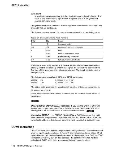
The internal machine format of a channel command word is shown in Figure 27.<br />
Figure 27. Channel Command Word, Format 0<br />
Byte Bits Usage<br />
0 0-7 Command code<br />
1-3 8-31 Address of data to operate upon<br />
4 32-37 Flags<br />
38-39 Must be specified as zeros<br />
5 40-47 Set to zeros by assembler<br />
6-7 48-63 Byte count or length of data<br />
If symbol is an ordinary symbol or a variable symbol that has been assigned an<br />
ordinary symbol, the ordinary symbol is assigned the value of the address of the<br />
first byte of the generated channel command word. The length attribute value of<br />
the symbol is 8.<br />
The following are examples of CCW and CCW0 statements:<br />
WRITE1 CCW 1,DATADR,X'48',X'5'<br />
WRITE2 CCW 1,DATADR,X'48',X'5'<br />
The object code generated (in hexadecimal) for either of the above examples is:<br />
1 xxxxxx 48 5<br />
where xxxxxx contains the address of DATADR, and DATADR must reside below 16<br />
megabytes.<br />
Using EXCP or EXCPVR access methods: If you use the EXCP or EXCPVR<br />
access method, you must use CCW or CCW0, because EXCP and EXCPVR do<br />
not support 31-bit data addresses in channel command words.<br />
Specifying RMODE: Use RMODE 24 with CCW or CCW0 to ensure that valid<br />
data addresses are generated. If you use RMODE ANY with CCW or CCW0, an<br />
invalid data address in the channel command word can result at execution time.<br />
CCW1 Instruction<br />
The CCW1 instruction defines and generates an 8-byte format-1 channel command<br />
word for input/output operations. A format-1 channel command word allows 31-bit<br />
data addresses. A format-0 channel command word generated by a CCW or CCW0<br />
instruction allows only a 24-bit data address. If a control section has not been<br />
established, CCW1 will initiate an unnamed (private) control section.<br />
116 <strong>HLASM</strong> V1R5 <strong>Language</strong> <strong>Reference</strong>


