HLASM Language Reference
HLASM Language Reference HLASM Language Reference
Operand Entries Registers You can specify a register in an operand for use as an arithmetic accumulator, a base register, an index register, and as a general depository for data to which you want to refer repeatedly. You must be careful when specifying a register whose contents have been affected by the execution of another machine instruction, the control program, or an IBM-supplied system macro instruction. For some machine instructions, you are limited in which registers you can specify in an operand. The expressions used to specify registers must have absolute values; in general, registers 0 through 15 can be specified for machine instructions. However, the following restrictions on register usage apply: If the NOAFPR assembler option is specified, then only the floating-point registers (0, 2, 4, or 6) may be specified for floating-point instructions. The even-numbered registers (0, 2, 4, 6, 8, 10, 12, 14) must be specified for the following groups of instructions: – The double-shift instructions – The fullword multiply and divide instructions – The move long and compare logical long instructions If the AFPR assembler option is specified, then one of the floating-point registers 0, 1, 4, 5, 8, 9, 12 or 13 can be specified for the instructions that use extended floating-point data in pairs of registers, such as AXR, SXR, LTXBR, and SQEBR. If the NOAFPR assembler option is specified, then either floating-point register 0 or 4 must be specified for these instructions. For a processor with a vector facility, the even-numbered vector registers (0, 2, 4, 6, 8, 10, 12, 14) must be specified in vector-facility instructions that are used to manipulate long floating-point data or 64-bit signed binary data in vector registers. The assembler checks the registers specified in the instruction statements of the above groups. If the specified register does not comply with the stated restrictions, the assembler issues a diagnostic message and does not assemble the instruction. Binary zeros are generated in place of the machine code. Register Usage by Machine Instructions Registers that are not explicitly coded in symbolic assembler language representation of machine instructions, but are nevertheless used by assembled machine instructions, are divided into two categories: Base registers that are implicit in the symbolic addresses specified. (See “Addresses” on page 87.) The registers can be identified by examining the object code or the USING instructions that assign base registers for the source module. Registers that are used by machine instructions, but don't appear in assembled object code. 86 HLASM V1R5 Language Reference
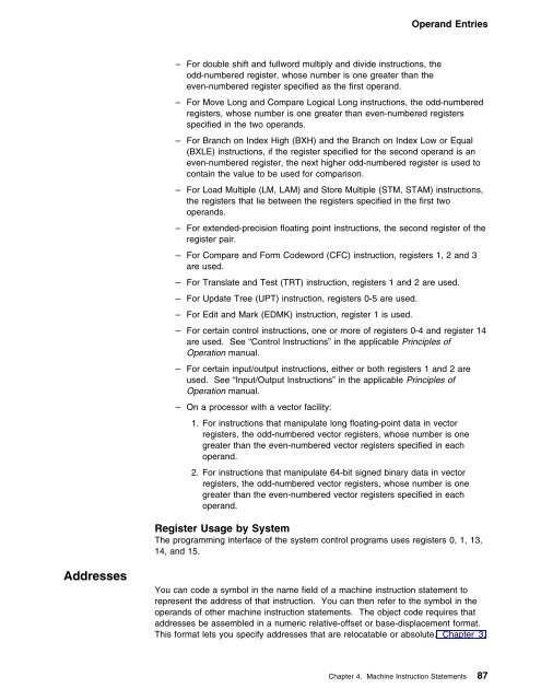
Operand Entries – For double shift and fullword multiply and divide instructions, the odd-numbered register, whose number is one greater than the even-numbered register specified as the first operand. – For Move Long and Compare Logical Long instructions, the odd-numbered registers, whose number is one greater than even-numbered registers specified in the two operands. – For Branch on Index High (BXH) and the Branch on Index Low or Equal (BXLE) instructions, if the register specified for the second operand is an even-numbered register, the next higher odd-numbered register is used to contain the value to be used for comparison. – For Load Multiple (LM, LAM) and Store Multiple (STM, STAM) instructions, the registers that lie between the registers specified in the first two operands. – For extended-precision floating point instructions, the second register of the register pair. – For Compare and Form Codeword (CFC) instruction, registers 1, 2 and 3 are used. – For Translate and Test (TRT) instruction, registers 1 and 2 are used. – For Update Tree (UPT) instruction, registers 0-5 are used. – For Edit and Mark (EDMK) instruction, register 1 is used. – For certain control instructions, one or more of registers 0-4 and register 14 are used. See “Control Instructions” in the applicable Principles of Operation manual. – For certain input/output instructions, either or both registers 1 and 2 are used. See “Input/Output Instructions” in the applicable Principles of Operation manual. – On a processor with a vector facility: 1. For instructions that manipulate long floating-point data in vector registers, the odd-numbered vector registers, whose number is one greater than the even-numbered vector registers specified in each operand. 2. For instructions that manipulate 64-bit signed binary data in vector registers, the odd-numbered vector registers, whose number is one greater than the even-numbered vector registers specified in each operand. Register Usage by System The programming interface of the system control programs uses registers 0, 1, 13, 14, and 15. Addresses You can code a symbol in the name field of a machine instruction statement to represent the address of that instruction. You can then refer to the symbol in the operands of other machine instruction statements. The object code requires that addresses be assembled in a numeric relative-offset or base-displacement format. This format lets you specify addresses that are relocatable or absolute. Chapter 3, Chapter 4. Machine Instruction Statements 87
- Page 56 and 57: Terms, Literals, and Expressions Fo
- Page 58 and 59: Terms, Literals, and Expressions I
- Page 60 and 61: Terms, Literals, and Expressions Th
- Page 62 and 63: Terms, Literals, and Expressions 1.
- Page 64 and 65: Terms, Literals, and Expressions
- Page 66 and 67: Terms, Literals, and Expressions
- Page 68 and 69: Terms, Literals, and Expressions Th
- Page 70 and 71: | Chapter 3. Program Structures and
- Page 72 and 73: Source Module A source module is co
- Page 74 and 75: The CSECT instruction can be used a
- Page 76 and 77: | in linker control statements for
- Page 78 and 79: This is not only convenient, but it
- Page 80 and 81: | SECT_A CSECT , Define section SEC
- Page 82 and 83: | For executable sections, the loca
- Page 84 and 85: Addressing | The System/390® and z
- Page 86 and 87: Addressing | Parts must always be r
- Page 88 and 89: Addressing Literal Pools ALPHA LR 3
- Page 90 and 91: Addressing If the symbol is the nam
- Page 92 and 93: Addressing External Symbol Dictiona
- Page 94 and 95: Addressing 74 HLASM V1R5 Language R
- Page 96 and 97: Part 2. Machine and Assembler Instr
- Page 98 and 99: General Instructions Chapter 4. Mac
- Page 100 and 101: Input/Output Operations For further
- Page 102 and 103: Branching with Extended Mnemonic Co
- Page 104 and 105: Symbolic Operation Codes variations
- Page 108 and 109: Operand Entries “Program Structur
- Page 110 and 111: Operand Entries Format │ Coded or
- Page 112 and 113: Examples of Coded Machine Instructi
- Page 114 and 115: Examples of Coded Machine Instructi
- Page 116 and 117: Examples of Coded Machine Instructi
- Page 118 and 119: Examples of Coded Machine Instructi
- Page 120 and 121: Chapter 5. Assembler Instruction St
- Page 122 and 123: *PROCESS Statement *PROCESS Stateme
- Page 124 and 125: ACONTROL Instruction ►►──
- Page 126 and 127: ACONTROL Instruction FLAG(PAGE0) in
- Page 128 and 129: AINSERT Instruction character_strin
- Page 130 and 131: AMODE Instruction alias_string is t
- Page 132 and 133: CATTR Instruction Figure 25. AMODE/
- Page 134 and 135: CATTR Instruction | statements for
- Page 136 and 137: CCW1 Instruction data_count is an a
- Page 138 and 139: CEJECT Instruction If symbol is an
- Page 140 and 141: CNOP Instruction Figure 29 (Page 2
- Page 142 and 143: COPY Instruction In the following e
- Page 144 and 145: CSECT Instruction symbol in the nam
- Page 146 and 147: DC Instruction ROUTINE B GAMMA DXD
- Page 148 and 149: DC Instruction duplication_factor c
- Page 150 and 151: DC Instruction Figure 33 (Page 2 of
- Page 152 and 153: DC Instruction With EBCDIC spaces
- Page 154 and 155: DC Instruction Further information
Operand Entries<br />
– For double shift and fullword multiply and divide instructions, the<br />
odd-numbered register, whose number is one greater than the<br />
even-numbered register specified as the first operand.<br />
– For Move Long and Compare Logical Long instructions, the odd-numbered<br />
registers, whose number is one greater than even-numbered registers<br />
specified in the two operands.<br />
– For Branch on Index High (BXH) and the Branch on Index Low or Equal<br />
(BXLE) instructions, if the register specified for the second operand is an<br />
even-numbered register, the next higher odd-numbered register is used to<br />
contain the value to be used for comparison.<br />
– For Load Multiple (LM, LAM) and Store Multiple (STM, STAM) instructions,<br />
the registers that lie between the registers specified in the first two<br />
operands.<br />
– For extended-precision floating point instructions, the second register of the<br />
register pair.<br />
– For Compare and Form Codeword (CFC) instruction, registers 1, 2 and 3<br />
are used.<br />
– For Translate and Test (TRT) instruction, registers 1 and 2 are used.<br />
– For Update Tree (UPT) instruction, registers 0-5 are used.<br />
– For Edit and Mark (EDMK) instruction, register 1 is used.<br />
– For certain control instructions, one or more of registers 0-4 and register 14<br />
are used. See “Control Instructions” in the applicable Principles of<br />
Operation manual.<br />
– For certain input/output instructions, either or both registers 1 and 2 are<br />
used. See “Input/Output Instructions” in the applicable Principles of<br />
Operation manual.<br />
– On a processor with a vector facility:<br />
1. For instructions that manipulate long floating-point data in vector<br />
registers, the odd-numbered vector registers, whose number is one<br />
greater than the even-numbered vector registers specified in each<br />
operand.<br />
2. For instructions that manipulate 64-bit signed binary data in vector<br />
registers, the odd-numbered vector registers, whose number is one<br />
greater than the even-numbered vector registers specified in each<br />
operand.<br />
Register Usage by System<br />
The programming interface of the system control programs uses registers 0, 1, 13,<br />
14, and 15.<br />
Addresses<br />
You can code a symbol in the name field of a machine instruction statement to<br />
represent the address of that instruction. You can then refer to the symbol in the<br />
operands of other machine instruction statements. The object code requires that<br />
addresses be assembled in a numeric relative-offset or base-displacement format.<br />
This format lets you specify addresses that are relocatable or absolute. Chapter 3,<br />
Chapter 4. Machine Instruction Statements 87


